WO2015015803A1 - 酸性ガス分離用積層体および該積層体を備えた酸性ガス分離用モジュール - Google Patents
酸性ガス分離用積層体および該積層体を備えた酸性ガス分離用モジュール Download PDFInfo
- Publication number
- WO2015015803A1 WO2015015803A1 PCT/JP2014/003992 JP2014003992W WO2015015803A1 WO 2015015803 A1 WO2015015803 A1 WO 2015015803A1 JP 2014003992 W JP2014003992 W JP 2014003992W WO 2015015803 A1 WO2015015803 A1 WO 2015015803A1
- Authority
- WO
- WIPO (PCT)
- Prior art keywords
- membrane
- gas separation
- gas
- laminate
- adhesive
- Prior art date
- Legal status (The legal status is an assumption and is not a legal conclusion. Google has not performed a legal analysis and makes no representation as to the accuracy of the status listed.)
- Ceased
Links
Images










Classifications
-
- B—PERFORMING OPERATIONS; TRANSPORTING
- B01—PHYSICAL OR CHEMICAL PROCESSES OR APPARATUS IN GENERAL
- B01D—SEPARATION
- B01D63/00—Apparatus in general for separation processes using semi-permeable membranes
- B01D63/08—Flat membrane modules
- B01D63/087—Single membrane modules
-
- B—PERFORMING OPERATIONS; TRANSPORTING
- B01—PHYSICAL OR CHEMICAL PROCESSES OR APPARATUS IN GENERAL
- B01D—SEPARATION
- B01D53/00—Separation of gases or vapours; Recovering vapours of volatile solvents from gases; Chemical or biological purification of waste gases, e.g. engine exhaust gases, smoke, fumes, flue gases, aerosols
- B01D53/22—Separation of gases or vapours; Recovering vapours of volatile solvents from gases; Chemical or biological purification of waste gases, e.g. engine exhaust gases, smoke, fumes, flue gases, aerosols by diffusion
-
- B—PERFORMING OPERATIONS; TRANSPORTING
- B01—PHYSICAL OR CHEMICAL PROCESSES OR APPARATUS IN GENERAL
- B01D—SEPARATION
- B01D53/00—Separation of gases or vapours; Recovering vapours of volatile solvents from gases; Chemical or biological purification of waste gases, e.g. engine exhaust gases, smoke, fumes, flue gases, aerosols
- B01D53/22—Separation of gases or vapours; Recovering vapours of volatile solvents from gases; Chemical or biological purification of waste gases, e.g. engine exhaust gases, smoke, fumes, flue gases, aerosols by diffusion
- B01D53/228—Separation of gases or vapours; Recovering vapours of volatile solvents from gases; Chemical or biological purification of waste gases, e.g. engine exhaust gases, smoke, fumes, flue gases, aerosols by diffusion characterised by specific membranes
-
- B—PERFORMING OPERATIONS; TRANSPORTING
- B01—PHYSICAL OR CHEMICAL PROCESSES OR APPARATUS IN GENERAL
- B01D—SEPARATION
- B01D63/00—Apparatus in general for separation processes using semi-permeable membranes
- B01D63/08—Flat membrane modules
-
- B—PERFORMING OPERATIONS; TRANSPORTING
- B01—PHYSICAL OR CHEMICAL PROCESSES OR APPARATUS IN GENERAL
- B01D—SEPARATION
- B01D63/00—Apparatus in general for separation processes using semi-permeable membranes
- B01D63/10—Spiral-wound membrane modules
- B01D63/101—Spiral winding
-
- B—PERFORMING OPERATIONS; TRANSPORTING
- B01—PHYSICAL OR CHEMICAL PROCESSES OR APPARATUS IN GENERAL
- B01D—SEPARATION
- B01D67/00—Processes specially adapted for manufacturing semi-permeable membranes for separation processes or apparatus
- B01D67/0079—Manufacture of membranes comprising organic and inorganic components
- B01D67/00793—Dispersing a component, e.g. as particles or powder, in another component
-
- B—PERFORMING OPERATIONS; TRANSPORTING
- B01—PHYSICAL OR CHEMICAL PROCESSES OR APPARATUS IN GENERAL
- B01D—SEPARATION
- B01D69/00—Semi-permeable membranes for separation processes or apparatus characterised by their form, structure or properties; Manufacturing processes specially adapted therefor
- B01D69/10—Supported membranes; Membrane supports
- B01D69/107—Organic support material
- B01D69/1071—Woven, non-woven or net mesh
-
- B—PERFORMING OPERATIONS; TRANSPORTING
- B01—PHYSICAL OR CHEMICAL PROCESSES OR APPARATUS IN GENERAL
- B01D—SEPARATION
- B01D69/00—Semi-permeable membranes for separation processes or apparatus characterised by their form, structure or properties; Manufacturing processes specially adapted therefor
- B01D69/12—Composite membranes; Ultra-thin membranes
- B01D69/1213—Laminated layers
-
- B—PERFORMING OPERATIONS; TRANSPORTING
- B01—PHYSICAL OR CHEMICAL PROCESSES OR APPARATUS IN GENERAL
- B01D—SEPARATION
- B01D69/00—Semi-permeable membranes for separation processes or apparatus characterised by their form, structure or properties; Manufacturing processes specially adapted therefor
- B01D69/14—Dynamic membranes
- B01D69/141—Heterogeneous membranes, e.g. containing dispersed material; Mixed matrix membranes
- B01D69/1411—Heterogeneous membranes, e.g. containing dispersed material; Mixed matrix membranes containing dispersed material in a continuous matrix
-
- B—PERFORMING OPERATIONS; TRANSPORTING
- B01—PHYSICAL OR CHEMICAL PROCESSES OR APPARATUS IN GENERAL
- B01D—SEPARATION
- B01D69/00—Semi-permeable membranes for separation processes or apparatus characterised by their form, structure or properties; Manufacturing processes specially adapted therefor
- B01D69/14—Dynamic membranes
- B01D69/141—Heterogeneous membranes, e.g. containing dispersed material; Mixed matrix membranes
- B01D69/142—Heterogeneous membranes, e.g. containing dispersed material; Mixed matrix membranes with "carriers"
-
- B—PERFORMING OPERATIONS; TRANSPORTING
- B01—PHYSICAL OR CHEMICAL PROCESSES OR APPARATUS IN GENERAL
- B01D—SEPARATION
- B01D71/00—Semi-permeable membranes for separation processes or apparatus characterised by the material; Manufacturing processes specially adapted therefor
- B01D71/06—Organic material
- B01D71/38—Polyalkenylalcohols; Polyalkenylesters; Polyalkenylethers; Polyalkenylaldehydes; Polyalkenylketones; Polyalkenylacetals; Polyalkenylketals
- B01D71/381—Polyvinylalcohol
-
- B—PERFORMING OPERATIONS; TRANSPORTING
- B01—PHYSICAL OR CHEMICAL PROCESSES OR APPARATUS IN GENERAL
- B01D—SEPARATION
- B01D71/00—Semi-permeable membranes for separation processes or apparatus characterised by the material; Manufacturing processes specially adapted therefor
- B01D71/06—Organic material
- B01D71/40—Polymers of unsaturated acids or derivatives thereof, e.g. salts, amides, imides, nitriles, anhydrides, esters
- B01D71/401—Polymers based on the polymerisation of acrylic acid, e.g. polyacrylate
-
- B—PERFORMING OPERATIONS; TRANSPORTING
- B01—PHYSICAL OR CHEMICAL PROCESSES OR APPARATUS IN GENERAL
- B01D—SEPARATION
- B01D53/00—Separation of gases or vapours; Recovering vapours of volatile solvents from gases; Chemical or biological purification of waste gases, e.g. engine exhaust gases, smoke, fumes, flue gases, aerosols
- B01D53/22—Separation of gases or vapours; Recovering vapours of volatile solvents from gases; Chemical or biological purification of waste gases, e.g. engine exhaust gases, smoke, fumes, flue gases, aerosols by diffusion
- B01D2053/221—Devices
-
- B—PERFORMING OPERATIONS; TRANSPORTING
- B01—PHYSICAL OR CHEMICAL PROCESSES OR APPARATUS IN GENERAL
- B01D—SEPARATION
- B01D2256/00—Main component in the product gas stream after treatment
- B01D2256/10—Nitrogen
-
- B—PERFORMING OPERATIONS; TRANSPORTING
- B01—PHYSICAL OR CHEMICAL PROCESSES OR APPARATUS IN GENERAL
- B01D—SEPARATION
- B01D2256/00—Main component in the product gas stream after treatment
- B01D2256/16—Hydrogen
-
- B—PERFORMING OPERATIONS; TRANSPORTING
- B01—PHYSICAL OR CHEMICAL PROCESSES OR APPARATUS IN GENERAL
- B01D—SEPARATION
- B01D2257/00—Components to be removed
- B01D2257/50—Carbon oxides
- B01D2257/504—Carbon dioxide
-
- B—PERFORMING OPERATIONS; TRANSPORTING
- B01—PHYSICAL OR CHEMICAL PROCESSES OR APPARATUS IN GENERAL
- B01D—SEPARATION
- B01D2323/00—Details relating to membrane preparation
- B01D2323/30—Cross-linking
-
- B—PERFORMING OPERATIONS; TRANSPORTING
- B01—PHYSICAL OR CHEMICAL PROCESSES OR APPARATUS IN GENERAL
- B01D—SEPARATION
- B01D71/00—Semi-permeable membranes for separation processes or apparatus characterised by the material; Manufacturing processes specially adapted therefor
- B01D71/06—Organic material
- B01D71/30—Polyalkenyl halides
- B01D71/32—Polyalkenyl halides containing fluorine atoms
- B01D71/36—Polytetrafluoroethylene
-
- B—PERFORMING OPERATIONS; TRANSPORTING
- B01—PHYSICAL OR CHEMICAL PROCESSES OR APPARATUS IN GENERAL
- B01D—SEPARATION
- B01D71/00—Semi-permeable membranes for separation processes or apparatus characterised by the material; Manufacturing processes specially adapted therefor
- B01D71/06—Organic material
- B01D71/76—Macromolecular material not specifically provided for in a single one of groups B01D71/08 - B01D71/74
-
- Y—GENERAL TAGGING OF NEW TECHNOLOGICAL DEVELOPMENTS; GENERAL TAGGING OF CROSS-SECTIONAL TECHNOLOGIES SPANNING OVER SEVERAL SECTIONS OF THE IPC; TECHNICAL SUBJECTS COVERED BY FORMER USPC CROSS-REFERENCE ART COLLECTIONS [XRACs] AND DIGESTS
- Y02—TECHNOLOGIES OR APPLICATIONS FOR MITIGATION OR ADAPTATION AGAINST CLIMATE CHANGE
- Y02C—CAPTURE, STORAGE, SEQUESTRATION OR DISPOSAL OF GREENHOUSE GASES [GHG]
- Y02C20/00—Capture or disposal of greenhouse gases
- Y02C20/40—Capture or disposal of greenhouse gases of CO2
Definitions
- the present invention relates to an acid gas separation laminate having an acid gas separation function and an acid gas separation module including the laminate.
- an acid gas separation module that separates an acid gas from a raw material gas by an acid gas separation membrane that selectively permeates the acid gas has been developed.
- the separation membrane utilizes the so-called facilitated transport membrane in which acid gas is transported to the opposite side of the membrane by the carrier in the separation membrane, and the difference in solubility between the acidic gas and the substance to be separated in the membrane and the diffusivity in the membrane.
- facilitated transport membrane in which acid gas is transported to the opposite side of the membrane by the carrier in the separation membrane, and the difference in solubility between the acidic gas and the substance to be separated in the membrane and the diffusivity in the membrane.
- dissolution diffusion membranes that perform separation.
- Patent Document 1 discloses a spiral membrane module in which a separation membrane, a supply-side channel member and a permeation-side channel member are wound around a central tube
- Patent Document 2 includes a flat membrane-type membrane module. It is disclosed.
- a spiral membrane module is configured by alternately stacking a leaf having a supply-side flow path member and a permeate-side flow path member while folding a separation membrane in half, and supplying a supply-side fluid and a permeate-side fluid.
- an adhesive is applied to three sides of the periphery of the laminate of the separation membrane and the permeate-side channel member to produce a separation membrane unit, and one or more of these units are connected to a central tube (fluid It is manufactured by spirally winding around a collecting pipe) and trimming (end face correction processing) both ends of the obtained cylindrical wound body.
- a separation membrane is arranged on one or both sides of the permeate-side channel member, and again, a separation membrane unit is produced by applying an adhesive to three sides of the peripheral edge of the laminate. One side to which no adhesive is applied is joined to the fluid collecting pipe.
- the sealing portion formed by the adhesive is extremely important from the viewpoint of preventing the mixing of the supply side fluid and the permeation side fluid and improving the separation performance.
- JP-A-11-226366 Japanese Patent Laid-Open No. 11-216341 JP 2009-18239 A Japanese Patent Laid-Open No. 3-68428
- the separation target substance is a gas (gas)
- gas gas
- the separation target substance is a gas (gas)
- the supply gas has a pressure equal to or higher than the atmospheric pressure, and a differential pressure is generated between the supply gas side and the permeate gas side, and the differential pressure is applied to the separation membrane having a reduced viscosity.
- the mechanical strength differs between the three sides sealed with the adhesive and the other portions, stress concentration tends to occur at the boundary between them. It can be seen that a large stress is applied to the boundary to cause defects in the separation membrane.
- An object of the present invention is to provide an acidic gas separation laminate applied to an acidic gas separation module that can suppress the occurrence of defects in a separation membrane, and an acidic gas separation module including the laminate. To do.
- the laminate for acidic gas separation of the present invention comprises a porous support in which a porous membrane and an auxiliary support membrane are laminated, An acidic gas separation promoting transport membrane having a function of separating the acidic gas in the raw material gas, disposed on the porous membrane side of the porous support;
- a laminated body for acidic gas separation comprising a permeated gas flow path member through which acidic gas that has permeated the acidic gas separation facilitated transport membrane is disposed on the auxiliary support membrane side of the porous support, Adhesive penetrates into the porous membrane with a width of 5 mm or more at the periphery of the laminate at a penetration rate of 60% or more, and the adhesive penetrates into the auxiliary support membrane and the gas channel member at a penetration rate of 60% or more.
- the penetration rate of the adhesive into the auxiliary support film and the gas flow path member is preferably 80% or more.
- the width of the stress buffer portion is preferably 0.1% or more and 50% or less of the width of the sealing portion.
- the width of the stress buffer portion is more preferably 40% or less of the width of the sealing portion.
- the sealing part does not need to be provided in the whole periphery of a laminated body, and should just be provided in the part which needs to be sealed among the periphery.
- the “adhesive penetration rate” means the filling rate of the adhesive with respect to the voids (holes) in each of the porous membrane, the auxiliary support membrane, and the gas flow path member.
- the SEM scanning electron microscope
- optical microscope was used to observe the cross section (cross section parallel to the sealing width direction) of the laminate after applying the adhesive, and after applying the adhesive.
- the ratio of the area of the adhesive filled in the hole to the area of the hole of each film and member is obtained by image processing.
- the three visual fields means, for example, that three visual fields are observed for each side when the sealing portions are provided on the three peripheral sides. Further, only one sealing portion is included in one field of view.
- the range in which the penetration rate from the end of the laminate is 60% or more in each film and member is specified as the sealing portion. And the area
- infiltrated rather than the sealing part is specified as a stress buffer part.
- the penetration rate of the adhesive into the auxiliary support film and the gas flow path member in the sealing portion is equal to or higher than the penetration rate of the adhesive into the porous membrane.
- the penetration rate of the adhesive from the filling area of the adhesive with respect to the area of the pores in each part of the porous membrane, the auxiliary support membrane and the permeating gas channel member every 0.01 mm width from the end of the laminate, and from the end
- the farthest position where the adhesive penetration rate in the porous membrane, auxiliary support membrane, and gas flow path member satisfies 60% or more is specified as the sealing portion, and the distance from the end portion to that position is the width of the sealing portion. It is defined as And from the end of the sealing portion to the position immediately before the adhesive penetration rate in the porous film becomes 0% is specified as the stress buffer portion, and the adhesive penetration rate becomes 0% from the end of the sealing portion.
- the distance to the immediately preceding position is defined as the width of the stress buffer portion. That is, the stress buffering portion may be a region where the penetration rate of the adhesive in at least the porous membrane is less than 60% and the adhesive penetrates into the auxiliary support membrane and the permeate side gas flow path member.
- the adhesive soaking rate of the support membrane and the permeate-side gas flow path member may be 60% or more or less than 60%.
- the width of the part may be non-uniform
- the penetration rate of the adhesive may not be uniform in the laminating direction, but at least in the range of 5 mm or more from the end portion, the filling rate is all in the porous membrane, the auxiliary support membrane, and the permeating gas channel member. It satisfies 60% or more.
- the width of the sealing portion may be 5 mm or more, but the larger the size, the smaller the effective separation area. Therefore, the width is preferably 70 mm or less.
- the porous membrane is made of a fluorine resin material.
- the porous membrane is particularly preferably made of polytetrafluoroethylene (PTFE).
- the adhesive is made of an epoxy resin.
- the acidic gas separation laminate of the present invention preferably has an intermediate layer between the porous membrane and the acidic gas separation promoting transport membrane.
- the intermediate layer is preferably a silicone resin.
- the acidic gas separation module of the present invention includes a permeate gas collecting pipe and the laminate for acidic gas separation of the present invention, and a permeate gas flow path member at an end portion where a sealing portion of the laminate is not formed. , And connected to a permeate gas collecting pipe.
- the acid gas separation module of the present invention may be a spiral type module or a flat membrane type module.
- the laminate for acidic gas separation of the present invention comprises a porous support in which a porous membrane and an auxiliary support membrane are laminated, an acidic gas separation promoting transport membrane, and a permeating gas channel member, and is porous. Adhering to the membrane at a penetration rate of 60% or more, and adjacent to the sealing part formed by penetration of the adhesive into the auxiliary support membrane and the gas flow path member at a penetration rate of 60% or more, At least the penetration rate of the adhesive in the porous membrane is less than 60%, and it is provided with a stress buffer portion formed by the adhesive penetrating into the auxiliary support membrane and the permeating gas flow path member. When it is assembled into a module and used for use, the stress concentration generated at the boundary due to the difference in mechanical strength between the area where the adhesive is soaked and the area where it is not, can be alleviated. Suppress the occurrence of It is possible.
- FIG. 1 It is a schematic perspective view which shows one Embodiment of the laminated film for acidic gas separation of this invention. It is a figure for demonstrating the effect of the laminated film for acidic gas separation of this invention. It is a figure which shows the example of a shape of the sealing part and stress buffer part of the laminated film for acidic gas separation of this invention. It is a figure which shows the other example of a shape of the sealing part of the laminated film for acidic gas separation of this invention, and a stress buffer part. It is a figure which shows the example of a design change of the laminated film for acidic gas separation of this invention. It is a partial cross section figure which shows the manufacturing process of the laminated film for acidic gas separation.
- FIG. 2A It is a partial cross section figure which shows the manufacturing process of the laminated film for acidic gas separation following FIG. 2A. It is a partial cross section figure which shows the manufacturing process of the laminated film for acidic gas separation following FIG. 2B. It is a figure which shows the coating method of the adhesive agent using a slot die. It is a figure which shows the other application
- FIG. 8A It is a figure which shows the spiral type module manufacturing process following FIG. 8A. It is a figure which shows the spiral type module manufacturing process following FIG. 8B (the 3). It is a figure which shows a spiral type module manufacturing process. It is a figure which shows the modification of a spiral type module manufacturing process.
- FIG. 12 is a cross-sectional view of the planar module shown in FIG. 11 taken along line XII-XII.
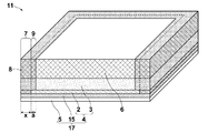
- FIG. 1A is a schematic perspective view showing a laminated configuration of an acid gas separating laminate 1 according to an embodiment of the present invention
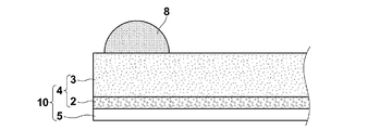
- FIG. 1B is an enlarged sectional view of an end portion of the laminate 1.
- the acid gas separation laminate 1 of this embodiment includes a porous support 4 in which a porous membrane 2 and an auxiliary support membrane 3 are laminated, and a porous support 4.
- Gas separation comprising a carrier that reacts directly or indirectly with the acidic gas in the source gas (supply gas) and an acidic gas separation-promoting transport membrane 5 containing a hydrophilic compound that carries the carrier, which is arranged on the membrane 2 side Permeate gas flow through which the composite gas (hereinafter referred to as gas separation membrane) 10 and the acidic gas that has permeated the separation support transport membrane 5 and the porous support 4 are disposed on the auxiliary support membrane 3 side of the porous support 4 And a road member 6.
- the sealing part 7 for sealing the inflow of gas to the porous support body 4 and the member 6 for permeate gas passages in three sides except one side among the peripheral edges (four sides) of the rectangular laminate 1.
- a stress buffering portion 9 is provided adjacent to the sealing portion 7.
- the sealing part 7 has a function of adhering the separation membrane 10 and the flow path member 6 and preventing mixing of the supply gas and the permeated gas. Further, the stress buffering portion 9 has a function of suppressing the occurrence of defects in the facilitated transport film 5.
- the sealing portion 7 is a portion configured by soaking the adhesive 8 into the porous support 4 and the flow path member 6, and 60% or more in the porous film 2 of the porous support 4 in the stacking direction.
- the adhesive 8 is soaked at the soaking rate
- the auxiliary support film 3 and the channel member 6 are portions where the adhesive 8 is soaked at a soaking rate of 60% or more.
- the width x of the sealing portion 7 (hereinafter, the sealing width x) is 5 mm or more from the end portion of the stacked body 1.
- the penetration rate of the adhesive 8 in the auxiliary support film 3 and the channel member 6 is preferably 80% or more, and more preferably 90% or more.
- the sealing width x By setting the sealing width x to 5 mm or more, a sufficient gas sealing function can be ensured. Since the adhesive does not necessarily spread with a uniform width, the sealing width x and the width a of the stress buffer portion 9 are changed at each position in the plane direction of the laminate 1 as shown in the schematic diagram of FIG. The smallest sealing width should just be 5 mm or more. On the other hand, when the sealing width x increases, the effective area for gas separation becomes narrow. Therefore, it is better not to be too long as long as the sealing width x is 5 mm or more over the entire region.
- the sealing width x is preferably 5 mm to 70 mm, and particularly preferably 10 mm to 50 mm.
- the stress buffer portion 9 is a portion where the penetration rate of the adhesive 8 in at least the porous film 2 is less than 60%.
- the penetration rate of the adhesive may be 60% or more or less than 60%, but at least the channel member 6.
- the penetration rate is preferably 10% or more.
- the penetration rate in the flow path member 6 is larger than the penetration rate in the porous film 2.
- the stress buffering portion 9 has a function of suppressing the occurrence of defects in the facilitated transport film 5 but is also a loss portion of the flow path. That is, the larger the region of the stress buffering portion 9, the more the passage of the permeate gas is lost.
- the width a of the stress buffering portion 9 is preferably as short as possible. By setting the width a to less than half (50% or less) of the sealing width x, it is possible to suppress film defects due to stress and to reduce the flow path loss.
- the width of the stress buffer portion 9 is more preferably 40% or less of the width of the sealing portion.
- the laminated body 1 has a rectangular shape, and a sealing portion 7 and a stress buffering portion 9 adjacent to the sealing portion 7 are formed on three sides of the peripheral edge except for one side. Note that the shape of the laminated body 1 and the region where the sealing portion 7 is formed can be appropriately set according to the module configuration to which the laminated film is applied.
- the laminate 1 is applied to a separation membrane module that separates an acid gas from a source gas (supply gas) containing an acid gas, but is particularly suitable when the supply gas contains water vapor.
- a separation membrane module that separates an acid gas from a source gas (supply gas) containing an acid gas, but is particularly suitable when the supply gas contains water vapor.
- the facilitated transport membrane 5 decreases its viscosity by absorbing moisture.
- the facilitated transport film 5 is pressed against the porous membrane side by the pressure (the differential pressure between the supply gas and the permeated gas) S due to the supply gas, and at that time, the region in which the adhesive is infiltrated and the adhesive infiltrate. Since the mechanical strength (rigidity) is different from the unexposed region, stress concentration occurs at the boundary between the two regions, which may cause defects in the facilitated transport film 5 at the boundary.
- the laminated body 1 which is embodiment of this invention is equipped with the stress buffer part 9 adjacent to the sealing part 7, as shown to an enlarged view in FIG. 1B, and relieve
- a predetermined pressure S is normally applied to the facilitated transport film 5 from the supply gas side due to the pressure difference (differential pressure) between the supply gas and the permeate gas.
- the rigidity of the porous support 4 and the flow path member 6 that supports the facilitated transport film 5 differs depending on the penetration rate of the adhesive (including the presence or absence of the penetration), so that the boundary position between regions having greatly different stiffnesses Stress concentration occurs in a portion of the facilitated transport film 5 indicated by an arrow P in FIG. 1B, for example.
- the stress buffering portion 9 is not provided, the sealing portion 7 and the region where no adhesive penetrates are adjacent to each other. Therefore, stress concentration at the boundary increases, and the facilitated transport film 5 is likely to be defective. Since the rigidity can be changed stepwise by providing 9, the stress concentration can be relaxed.
- the soaking area 9a may be gradually changed.
- the soaking region may have a distance from the end portion changed in the stacking direction.
- the penetration rate of the adhesive is determined by image processing for each region having a width of 0.01 mm from the end portion on the cut surface, for example, for each region c i sandwiched by a dashed line in FIG. 1D.
- the ratio of the area filled with the adhesive to the area of the hole of each layer is calculated and calculated.
- the width of the sealing portion and the width of the stress buffer portion are determined from the penetration rate of the adhesive.
- the adhesive penetration rate in the porous membrane is determined, and the end portion of the measurement unit region that satisfies the adhesive penetration rate of 60% or more in the porous membrane most (in FIG. 1D, the region c n) distant measurement unit region is a region a sealing portion 7 up to and including the distant side edge of a stack end of the measuring unit region c n from the end of the stack from The distance to 9b is the width of the sealing portion 7.
- infiltration first adhesive region c n + 1 adjacent to the plane direction of the region c n The rate is less than 60%.
- a region containing up to the measurement unit areas c z-1 of the immediately preceding in the measurement unit region from the edge 9b of the region c z where adhesive soaks rate becomes 0% in the porous membrane of the sealing portion 7 with stress buffer 9 The distance from the end 9b of the sealing portion 7 to the end 9c of the region cz-1 immediately before the adhesive penetration rate becomes 0% is the width of the stress buffering portion 9. As shown in FIG.
- the adhesive soaking area may vary greatly depending on the position in the surface direction in which the sealing portion is formed, and therefore the width of the sealing portion and the width of the stress buffering portion are a plurality of locations.
- the average value of the values obtained in the cross section (for example, three locations) is used.
- the gas separation membrane 10 includes an acidic gas separation facilitated transport membrane 5 and a porous support 4 that supports the facilitated transport membrane 5 and is provided on the permeate gas flow path member 6 side.
- the acidic gas separation promoting transport membrane 5 contains at least a carrier that reacts directly or indirectly with the acidic gas in the raw material gas and a hydrophilic compound that carries the carrier, and has a function of selectively permeating the acidic gas from the raw material gas.
- the facilitated transport film 5 generally has higher heat resistance than the dissolution diffusion film, the acidic gas can be selectively permeated even under temperature conditions of, for example, 100 ° C. to 200 ° C.
- the hydrophilic compound absorbs the water vapor and the facilitated transport film containing the hydrophilic compound retains moisture, so that carriers can be more easily transported. Separation efficiency is increased as compared with the case where a dissolution diffusion membrane is used.
- Membrane area facilitated transport membrane 5 is not particularly limited, it is preferably 0.01 m 2 or more 1000 m 2 or less, more preferably 0.02 m 2 or more 750 meters 2 or less, 0.025 m 2 or more 500 meters 2 Even more preferably: Furthermore, the membrane area, from a practical point of view, is preferably 1 m 2 or more 100 m 2 or less. By setting it as each lower limit or more, an acidic gas can be efficiently isolate
- the thickness of the facilitated transport film 5 is not particularly limited, but is preferably 1 to 200 ⁇ m, more preferably 2 to 175 ⁇ m. A thickness in such a range is preferable because sufficient gas permeability and separation selectivity can be realized.
- hydrophilic polymer A hydrophilic polymer is mentioned as a hydrophilic compound.
- the hydrophilic polymer functions as a binder, holds water, and exhibits the function of separating the acidic gas by the acidic gas carrier.
- the hydrophilic compound can be dissolved in water or dispersed in water to form a coating solution, and the acidic gas separation layer has high hydrophilicity (humidity retention) from the viewpoint of having high hydrophilicity (humidity retention). It is preferable to absorb water having a mass of 5 to 1000 times the mass of the hydrophilic compound itself.
- hydrophilic polymer examples include, for example, polyvinyl alcohol-polyacrylic acid salt, polyvinyl alcohol-polyacrylic acid (PVA-PAA) copolymer, polyvinyl alcohol, polyacrylic acid, from the viewpoint of hydrophilicity, film forming property, strength, and the like. Acid, polyacrylate, polyvinyl butyral, poly-N-vinyl pyrrolidone, poly-N-vinyl acetamide, and polyacrylamide are preferred, and PVA-PAA copolymer is particularly preferred.
- the PVA-PAA copolymer has a high water absorption capacity and a high strength in a hydrogel state at the time of high water absorption.
- the content of polyacrylate in the PVA-PAA copolymer is, for example, preferably from 5 mol% to 95 mol%, more preferably from 30 mol% to 70 mol%.
- polyacrylic acid salts include alkali metal salts such as sodium salt and potassium salt, as well as ammonium salts and organic ammonium salts.
- An example of a commercially available PVA-PAA copolymer is Clastomer AP20 (manufactured by Kuraray Co., Ltd.).
- Acid gas carriers are various water-soluble compounds that have an affinity with acid gas (for example, carbon dioxide gas) and show basicity, and indirectly react with acid gas, or itself itself. It reacts with acid gas. Indirect reaction with acid gas includes, for example, reaction with other gas contained in the supply gas to generate a basic compound, and reaction of the basic compound with acid gas.
- acid gas carrier specifically, OH in contact with steam (water vapor) - was released, the OH - is selectively incorporating the CO 2 in the film by reacting with CO 2 Alkali metals and alkali metal compounds that can be used.
- the acid gas carrier that directly reacts with the acid gas include basic compounds such as nitrogen-containing compounds and sulfur oxides.
- the alkali metal compound examples include at least one selected from the group consisting of an alkali metal carbonate, an alkali metal bicarbonate, and an alkali metal hydroxide, and a polydentate that forms a complex with an alkali metal ion in an aqueous solution containing the alkali metal compound.
- An aqueous solution to which a ligand is added may be mentioned.
- an alkali metal or an alkali metal compound is used in the meaning including its salt and its ion in addition to itself.
- Examples of the alkali metal carbonate include lithium carbonate, sodium carbonate, potassium carbonate, rubidium carbonate, and cesium carbonate.
- Examples of the alkali metal bicarbonate include lithium bicarbonate, sodium bicarbonate, potassium bicarbonate, rubidium bicarbonate, and cesium bicarbonate.
- Examples of the alkali metal hydroxide include lithium hydroxide, sodium hydroxide, potassium hydroxide, rubidium hydroxide, and cesium hydroxide. Among these, an alkali metal carbonate is preferable, and a compound containing potassium, rubidium, and cesium having high solubility in water as an alkali metal element is preferable from the viewpoint of good affinity with acidic gas.
- the phenomenon that the facilitated transport film becomes a gel with moisture absorbed during manufacture and the facilitated transport film adheres to each other and other members during manufacture (blocking) is present. It is likely to occur.
- this blocking occurs, when the facilitated transport film is peeled off, the facilitated transport film may cause defects due to the sticking, resulting in gas leakage. Therefore, in this embodiment, it is preferable to prevent blocking.
- the carrier preferably contains two or more alkali metal compounds. This is because by using two or more types of carriers, the same type of carriers in the film can be separated from each other, and blocking non-uniformity can be generated and blocking suppression can be achieved. Furthermore, it is more preferable that the carrier contains a first alkali metal compound having deliquescence and a second alkali metal compound having a lower deliquescence and a lower specific gravity than the first alkali metal compound. Specifically, the first alkali metal compound includes cesium carbonate, and the second alkali metal compound includes potassium carbonate.
- the carrier contains the first alkali metal compound and the second alkali metal compound
- the second alkali metal compound having a small specific gravity is arranged on the film surface side of the facilitated transport film (that is, unevenly disposed on the surface side of the facilitated transport film).
- the first alkali metal compound having a large specific gravity is disposed inside the facilitated transport membrane (that is, unevenly disposed on the porous support side of the facilitated transport membrane).
- positioned at the film surface side has lower deliquescence property than a 1st alkali metal compound, compared with the case where a 1st alkali metal compound is arrange
- the first alkali metal compound having high deliquescence is disposed inside the membrane, blocking is suppressed and the separation efficiency of carbon dioxide gas is reduced as compared with the case where the second alkali metal compound is simply disposed over the entire membrane. Can be increased.
- the facilitated transport film 5 is a second layer on the surface side opposite to the porous support 4. And a first layer on the porous support 4 side below.
- the facilitated transport film 5 is composed of a hydrophilic compound (hydrophilic polymer) as a whole, and the second layer mainly contains a second alkali metal compound having low deliquescence and low specific gravity. ing.
- a first alkali metal compound having mainly deliquescence exists in the first layer.
- the thickness of the second layer is not particularly limited, but is preferably 0.01 to 150 ⁇ m and more preferably 0.1 to 100 ⁇ m in order to exhibit a sufficient deliquescent suppression function.
- the second layer containing the second alkali metal compound is unevenly distributed on the surface side, and the first layer containing the first alkali metal compound can be spread below the second layer.
- the interface between the two layers may not be clear and may be divided in a state in which the concentration of the two changes in an inclined manner.
- the interface is not planar and may have a gentle undulation.
- the deliquescence of the membrane is suppressed by the action of the second layer containing the second alkali metal compound having low deliquescence and low specific gravity.
- the reason why the second alkali metal compound is unevenly distributed is considered to be due to the difference in specific gravity between two or more alkali metals. That is, by setting one of two or more types of alkali metals to a low specific gravity, it is possible to localize a lighter specific gravity in the coating solution at the time of film formation. Then, while maintaining the high transport force such as carbon dioxide of the first alkali metal compound having the deliquescence contained in the first layer inside the film, the surface of the second layer film is more crystalline than the second alkali metal compound has. Condensation and the like can be prevented due to the property of being easily converted. Thereby, while blocking can be suppressed, the separation efficiency of a carbon dioxide gas can be improved.
- the second alkali metal compound since the second alkali metal compound only needs to be on the film surface side to prevent blocking, the second alkali metal compound is preferably contained in a smaller amount than the first alkali metal compound. Thereby, the amount of the first alkali metal compound having high deliquescence is relatively large in the entire membrane, and the carbon dioxide separation efficiency can be further increased.
- the ratio of the second alkali metal compound to the first alkali metal compound is not particularly limited, but the first alkali metal compound is preferably 50 parts by mass or more with respect to 100 parts by mass of the second alkali metal compound, and 100 parts by mass. More preferably, it is at least part. As an upper limit, it is preferable that it is 100000 mass parts or less, and it is more preferable that it is 80000 mass parts or less. By adjusting the ratio of the two in this range, it is possible to achieve both blocking properties and handling properties at a high level.
- the number of types of two or more types of alkali metal compounds is determined by the type of alkali metal, and even if the counter ions are different, it is not counted as one type. That is, even if potassium carbonate and potassium hydroxide are used in combination, it is counted as one type.
- alkali metal compounds those shown in Table 1 below are preferable.
- an alkali metal compound is indicated by the name of an alkali metal, but a salt or ion thereof may be used.
- the content of the acidic gas carrier in the facilitated transport membrane as a whole depends on the ratio to the amount of the hydrophilic compound and the type of acidic gas carrier, but prevents salting out before coating and ensures the separation function of acidic gas.
- the content is preferably 0.3% by mass to 30% by mass, more preferably 0.5% by mass to 25% by mass, and particularly preferably 1% by mass to 20% by mass.
- the content of the two or more kinds of alkali metal compounds is determined based on the total amount of solids such as a hydrophilic compound and two or more kinds of alkali metal compounds that are the main components of the film.
- the mass ratio of two or more alkali metal compounds is preferably 25% by mass or more and 85% by mass or less, and more preferably 30% by mass or more and 80% by mass or less. By setting this amount within the above range, the gas separation function can be sufficiently exhibited.
- the second alkali metal compound (alkali metal compound unevenly distributed on the surface side of the facilitated transport film 5) having lower deliquescence and lower specific gravity than the first alkali metal compound, It is preferably 0.01% by mass or more and 0.02% by mass or more with respect to the total mass (typically, the total mass of the separated layer after drying) of two or more kinds of alkali metal compounds and the like. It is more preferable that Although there is no upper limit in particular, it is preferable that it is 10 mass% or less, and it is more preferable that it is 7.5 mass% or less. If this amount is too small, blocking may not be prevented, and if it is too large, handling may not be possible.
- Nitrogen-containing compounds include ammonia, ammonium salts, various linear and cyclic amines, amine salts, ammonium salts and the like. These water-soluble derivatives can also be preferably used. Since carriers that can be retained in the facilitated transport film for a long period of time are useful, amine-containing compounds that are difficult to evaporate, such as amino acids and betaines, are particularly preferred.
- amino acids such as glycine, alanine, serine, proline, histidine, taurine, diaminopropionic acid, hetero compounds such as pyridine, histidine, piperazine, imidazole, triazine, monoethanolamine, diethanolamine, triethanolamine, monopropanolamine , Alkanolamines such as dipropanolamine and tripropanolamine, cyclic polyetheramines such as cryptand [2.1] and cryptand [2.2], cryptand [2.2.1] and cryptand [2.2 .2] and the like, porphyrins, phthalocyanines, ethylenediaminetetraacetic acid and the like can be used.
- amino acids such as cystine and cysteine, polythiophene, dodecylthiol and the like can be used.
- the facilitated transport membrane may contain other components (additives) other than the hydrophilic polymer, the acidic gas carrier and water as long as the separation characteristics are not adversely affected.
- the coating liquid film is cooled.
- a gelling agent that controls the so-called set property a viscosity adjusting agent that adjusts the viscosity at the time of coating when the coating solution is coated with a coating device, a crosslinking agent for improving the film strength of the facilitated transport film,
- examples include acid gas absorption accelerators, surfactants, catalysts, auxiliary solvents, membrane strength modifiers, and detection agents for facilitating the inspection of the formed facilitated transport membrane for defects.
- the porous support 4 that supports the facilitated transport film 5 is formed by laminating the porous film 2 and the auxiliary support film 3.
- the mechanical strength can be improved, and there is an effect that wrinkles do not occur even when handled by a coating machine or the like, and productivity can be improved.
- the porous membrane 2 has an acid gas permeability such as carbon dioxide which is a gas to be separated.
- the porous membrane 2 preferably has a small pore diameter from the viewpoint of suppressing penetration of the facilitated transport material during formation of the facilitated transport film.
- the maximum pore size is preferably 1 ⁇ m or less.
- the lower limit of the pore diameter is not particularly limited, but is about 0.001 ⁇ m.
- the maximum pore diameter means a value measured and calculated by the bubble point method. For example, it can measure by the bubble point method (based on JISK3832) using the palm porometer made from PMI as a measuring apparatus.
- the maximum pore size is the largest pore size value in the pore size distribution of the porous membrane.
- the thickness of the porous membrane 2 is preferably 1 ⁇ m or more and 100 ⁇ m or less.
- the surface of the porous membrane 2 on the side in contact with the facilitated transport membrane 5 is a hydrophobic surface. If the surface is hydrophilic, the facilitated transport film containing moisture in the use environment is likely to penetrate into the porous portion, and there is a concern that the film thickness distribution and performance deterioration with time may occur.
- hydrophobic means that the contact angle of water at room temperature (25 ° C.) is about 80 ° or more.
- the porous membrane 2 is a porous resin sheet made of a resin material such as polyester, polyolefin, polyamide, polyimide, polysulfonamide, polysulfone, polycarbonate, polyacrylonitrile or the like.
- the acidic gas separation module to which the laminated body for acidic gas separation according to the present invention is applied is used, for example, under a high temperature of about 130 ° C. and humidification using steam, although the use temperature varies depending on the application. There are many cases. Therefore, it is preferable that the porous membrane is made of a material having heat resistance with little change in pore structure even at 130 ° C. and having low hydrolyzability. From such a point of view, those formed by including a resin selected from the group consisting of fluorine-containing resins such as polypropylene, polytetrafluoroethylene (PTFE), and polyvinylidene fluoride (PVDF) are preferred and most preferred. Is a PTFE porous membrane.
- fluorine-containing resins such as polypropylene, polytetrafluoroethylene (PTFE), and polyvinylidene fluoride (PVDF) are preferred and most preferred. Is a PTFE porous membrane.
- the auxiliary support membrane 3 is provided to reinforce the porous membrane 2 and is not particularly limited as long as the strength, stretch resistance and gas permeability are good, and a nonwoven fabric, a woven fabric, a knitted fabric, and A mesh having a maximum pore diameter of 0.001 ⁇ m or more and 500 ⁇ m can be appropriately selected and used.
- the thickness of the auxiliary support film 3 is preferably 50 ⁇ m or more and 300 ⁇ m or less.
- the auxiliary support membrane 3 is also preferably made of a material having heat resistance and low hydrolyzability, like the porous membrane 2 described above.
- the fibers constituting the nonwoven fabric, woven fabric, and knitted fabric include fibers made of modified polyamides such as polypropylene and aramid, fluorine-containing resins such as polytetrafluoroethylene and polyvinylidene fluoride, which are excellent in durability and heat resistance. preferable. It is preferable to use the same material as the resin material constituting the mesh. Of these materials, it is particularly preferable to use a nonwoven fabric made of polypropylene (PP) which is inexpensive and has high mechanical strength.
- PP polypropylene
- the permeate gas channel member 6 is a member through which the acidic gas that has reacted with the carrier and permeated the gas separation membrane 10 flows.
- the permeate gas flow path member 6 has a function as a spacer, has a function of flowing an acidic gas to the permeate gas collecting pipe side, and further has a function of permeating an adhesive described later.
- the member 6 is preferably an uneven member with a gap. Examples include tricot knitting and plain weaving. Further, assuming that a raw material gas containing water vapor flows at a high temperature, it is preferable that the permeate gas flow path member has moisture and heat resistance, like the gas separation membrane.
- polyester-based such as epoxy-impregnated polyester
- polyolefin-based such as polypropylene
- fluorine-based such as polytetrafluoroethylene
- metal-based such as wire mesh
- the thickness of the permeating gas channel member 6 is not particularly limited, but is preferably 100 ⁇ m or more and 1000 ⁇ m or less, more preferably 150 ⁇ m or more and 950 ⁇ m or less, and further preferably 200 ⁇ m or more and 900 ⁇ m or less. Further, the permeating gas channel member may be the same type or a single type, but the same type or a plurality of types may be laminated.
- the adhesive 8 used for the sealing portion 7 and the stress buffering portion 9 has heat and humidity resistance.
- the material is not particularly limited as long as it has heat and humidity resistance.
- epoxy resin vinyl chloride copolymer, vinyl chloride-vinyl acetate copolymer, vinyl chloride-vinylidene chloride copolymer, vinyl chloride-acrylonitrile.
- Copolymer butadiene-acrylonitrile copolymer, polyamide resin, polyvinyl butyral, polyester, cellulose derivative (nitrocellulose, etc.), styrene-butadiene copolymer, various synthetic rubber resins, phenol resin, melamine resin, phenoxy resin, Examples include silicone resins and urea formamide resins. Particularly preferred is an epoxy resin. In order to improve the wettability of the adhesive, it may contain a solvent or a surfactant.
- the porous membrane 2 is a PTFE porous sheet
- the auxiliary support membrane 3 is a porous support 4 made of PP nonwoven fabric
- the flow path member 6 is made of PP woven fabric
- the sealing portion 7 It is a particularly preferable form to use an epoxy resin as the adhesive 8 used in the above.
- the gas separation membrane 10 having the facilitated transport membrane 5 on the support 4 may have another layer other than the facilitated transport membrane 5 on the support 4.
- Examples of other layers include an undercoat layer provided between the porous support 4 and the facilitated transport film 5, an intermediate layer, and a protective layer (eg, a carrier elution preventing layer) provided on the facilitated transport film 5.
- a protective layer eg, a carrier elution preventing layer
- FIG. 1E is a schematic perspective view showing a laminated configuration of the acid gas separation laminate 11 of the design change example of the embodiment.
- the acidic gas separation membrane 17 includes an intermediate layer 15 between the porous support 4 and the facilitated transport membrane 5.
- the facilitated transport film needs to retain a large amount of moisture in the film in order for the carrier to function sufficiently, a hydrophilic compound having extremely high water absorption and water retention is used.
- a hydrophilic compound having extremely high water absorption and water retention.
- the facilitated transport membrane As the content of a carrier such as a metal carbonate increases, the water absorption increases and the separation performance of the acid gas improves. For this reason, the facilitated transport membrane is often a gel membrane or a low-viscosity membrane.
- the porous membrane of the acid gas separation membrane has hydrophobicity at least on the surface in contact with the facilitated transport membrane from the viewpoint of suppressing the penetration of the facilitated transport material when forming the facilitated transport membrane. Is preferred.
- a raw material gas having a temperature of 100 to 130 ° C. and a humidity of about 90% is supplied at a pressure of about 1.5 MPa when the acidic gas is separated.
- the facilitated transport membrane gradually enters the porous support, and the acid gas separation ability tends to decrease with time.
- the acidic gas separation membrane includes an intermediate layer 15 between the porous membrane and the facilitated transport membrane that more effectively suppresses the penetration of the facilitated transport material (membrane) into the porous membrane. Is preferred.
- the intermediate layer 15 is not particularly limited as long as it is a hydrophobic layer having gas permeability, but preferably has a gas permeability and is denser than the porous membrane. By providing the intermediate layer 15, it is possible to prevent the facilitated transport film 5 having high uniformity from entering the porous film 2.
- the intermediate layer 15 may be formed on the porous film 2, but may have a soaked area that is soaked in the porous film 2. The smaller the permeation area, the better the adhesiveness between the porous membrane 2 and the intermediate layer 15 within the range.
- the intermediate layer 15 is preferably a polymer layer having a siloxane bond in the repeating unit.
- a polymer layer include silicone-containing polyacetylene such as organopolysiloxane (silicone resin) and polytrimethylsilylpropyne.
- organopolysiloxane include those represented by the following general formula.
- n represents an integer of 1 or more.
- the average value of n is preferably in the range of 10 to 1,000,000, more preferably in the range of 100 to 100,000.
- R 1n , R 2n , R 3 , and R 4 are each a group consisting of a hydrogen atom, an alkyl group, a vinyl group, an aralkyl group, an aryl group, a hydroxyl group, an amino group, a carboxyl group, and an epoxy group. Indicates which one is selected. Note that n R 1n and R 2n may be the same or different. In addition, the alkyl group, aralkyl group, and aryl group may have a ring structure.
- these alkyl groups, vinyl groups, aralkyl groups, and aryl groups may have a substituent, and the substituents are alkyl groups, vinyl groups, aryl groups, hydroxyl groups, amino groups, carboxyl groups, epoxy groups. Or selected from fluorine atoms. These substituents may further have a substituent if possible.
- the alkyl group, vinyl group, aralkyl group, and aryl group selected from R 1n , R 2n , R 3 , and R 4 are an alkyl group having 1 to 20 carbon atoms, vinyl, and the like from the viewpoint of availability. More preferred are an aralkyl group having 7 to 20 carbon atoms and an aryl group having 6 to 20 carbon atoms.
- R 1n , R 2n , R 3 , and R 4 are preferably methyl groups or epoxy-substituted alkyl groups.
- PDMS polydimethylsiloxane
- the silicone resin layer is preferably formed by coating.
- the coating solution used for film formation contains a monomer, dimer, trimer, oligomer, prepolymer, or mixture of compounds that form a silicone resin layer, and further includes a curing agent, a curing accelerator, and a crosslinking agent. , Thickeners, reinforcing agents and the like may be included.
- the intermediate layer 15 is a film having gas permeability, but if it is too thick, the gas permeability may be significantly reduced.
- the intermediate layer 15 may be thin as long as it covers the entire surface of the porous film 2 without passing through. Considering this point, the film thickness of the intermediate layer 15 is preferably 0.01 ⁇ m or more and 30 ⁇ m or less, and more preferably 0.1 ⁇ m or more and 15 ⁇ m or less.
- FIGS. 2A to 2C are partially enlarged cross-sectional views each showing a manufacturing process.
- a porous support 4 in which a porous film 2 and an auxiliary support film 3 are laminated is prepared.
- the coating composition for formation of an acidic gas separation promotion transport film is adjusted.
- the coating liquid composition is prepared by adding the above-mentioned hydrophilic polymer, acidic gas carrier (for example, carbon dioxide carrier), and water, and, if necessary, other additives such as a gelling agent and a crosslinking agent in appropriate amounts. Add to water (room temperature water or warm water) and stir well. If necessary, heat with stirring to promote dissolution.
- a hydrophilic polymer, an acidic gas carrier, and other components may be added separately to water, or those previously mixed may be added.
- the coating liquid composition is applied onto the porous film 2 of the porous support 4 and dried to form the facilitated transport film 5 on the porous support 4.
- the gas separation composite membrane of the porous support 4 and the facilitated transport membrane 5 is the gas separation membrane 10.
- the adhesive 8 is applied to three sides of the peripheral edge so that the auxiliary support film 3 becomes the upper surface (see FIG. 4A).
- the gas separation membrane 10 is placed on the flow path member 6 so that the application surface of the adhesive 8 of the gas separation membrane 10 is in contact (or the adhesive of the gas separation membrane 10).
- the adhesive 8 is permeated into the auxiliary support film 3 and the eyes (holes) of the channel member 6 by applying tension in the film surface direction (with the channel member 6 placed on the application surface).
- the sealing portion 7 formed by continuously infiltrating the adhesive 8 in the stacking direction of the porous membrane 2, the auxiliary support membrane 3, and the gas flow path member 6, and this example the adhesive 8 does not permeate into the porous membrane 2, and adhesive spreading portions 9 and 19 formed by permeating the adhesive 8 only into the auxiliary support membrane 3 and the gas flow path member 6 are formed.
- the spreading portions 9 and 19 are shown as being symmetric, but they are not necessarily formed symmetrically.
- the end portion shown in FIG. 2C is cut at, for example, the position of the CC line, and so-called trimming (end face correction processing) is performed to obtain the laminate 1.
- the relationship between the width x of the sealing portion 7 and the width a of the adhesive spreading portion 9 (in this example, the spreading portion forms the stress buffering portion 9) satisfies a ⁇ 0.5x. Cut at the position.
- the adhesive does not penetrate into the porous film 2, but as described with reference to FIG. 1C, the porous film 2 has a filling rate of less than 60%. The adhesive may penetrate.
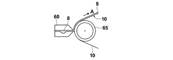
- a slot die 60 can be used as shown in FIGS. 3A and 3B.
- the separation membrane 10 may be conveyed in the A direction by using a conveyance roll 65, and the adhesive 8 may be applied by the slot die 60.
- the adhesive 8 may be applied while being transported in a direction B perpendicular to 60.
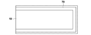
- a stamp 70 provided with a sponge 72 having a shape corresponding to the coating area is used, and the sponge 72 soaked with the adhesive 8 is used as a separation membrane.
- a method may be used in which the adhesive 8 is applied by impregnating the brush with an adhesive using a brush-like jig and applying the brush onto the surface of the separation membrane 10. If these adhesive coating methods are used, it is easy to automate the manufacturing process, and uniform coating can be performed by controlling the coating amount and coating width.
- the acidic gas separation laminate of the present invention is used by being incorporated in an acidic gas separation module.
- the module for separating acidic gas of the present invention comprises a permeate gas collecting pipe and the laminated film of the present invention connected to the collecting pipe.
- the acid gas separation module can take various module forms such as a spiral type and a flat membrane type.
- the laminate shown in FIG. 1A described above has the minimum unit configuration of the present invention, but the laminate of the present invention can be used by appropriately changing the configuration according to the applied module configuration.
- a specific acidic gas separation module to which the acidic gas separation laminate of the present invention is applied will be described.
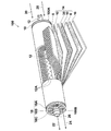
- FIG. 5 is a partially cutaway view showing a spiral acid gas separation module 100 (hereinafter referred to as a spiral type module 100) which is a first embodiment of the acid gas separation module of the present invention.
- a spiral type module 100 which is a first embodiment of the acid gas separation module of the present invention.
- the spiral module 100 has a basic structure in which the outermost periphery is covered with a coating layer 16 in a state where one or more laminated bodies 14 described later are wound around the permeating gas collecting pipe 12.
- the telescope prevention plates 18 are attached to both ends of these units, respectively.
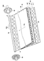
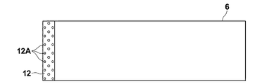
- FIG. 6 is a perspective view showing a state before the laminated body 14 is wound around the permeate gas collecting pipe 12, and FIG. 7 shows a part of a cylindrical wound body in which the laminated body is wound around the permeate gas collecting pipe. It is sectional drawing.
- the permeated gas collecting pipe 12 is a cylindrical pipe having a plurality of through holes 12A formed in the pipe wall.
- the one end side (one end 100A side) of the permeate gas collecting pipe 12 is closed, the other end side (the other end 100B side) of the permeate gas collecting pipe 12 is opened, and the carbon dioxide collects from the through hole 12A through the laminate.
- a discharge port 26 from which acidic gas 22 such as gas is discharged is provided.
- the shape of the through hole 12A is not particularly limited, but a circular hole of 0.5 to 20 mm ⁇ is preferably opened. Moreover, it is preferable that the through holes 12 ⁇ / b> A are arranged uniformly with respect to the surface of the permeate gas collecting pipe 12.
- the covering layer 16 is formed of a blocking material capable of blocking the raw material gas 20 passing through the acidic gas separation module 100.
- This blocking material preferably further has heat and humidity resistance.
- heat resistance in the heat and humidity resistance means having a heat resistance of 80 ° C. or higher.
- the heat resistance of 80 ° C. or higher means that the shape before storage is maintained even after being stored for 2 hours under a temperature condition of 80 ° C. or higher, and curling that can be visually confirmed by heat shrinkage or heat melting does not occur.
- “moisture resistance” of the heat and humidity resistance is a curl that can be visually confirmed by heat shrinkage or heat melting even after being stored at 40 ° C. and 80% RH for 2 hours. It means not occurring.
- the telescope prevention plate 18 has an outer peripheral annular portion 18A, an inner peripheral annular portion 18B, and a radial spoke portion 18C, and each is preferably formed of a heat and moisture resistant material.
- the laminated body 14 is formed by laminating a permeated gas flow path member 6 on a leaf 50 formed by sandwiching a supply gas flow path member 30 inside an acidic gas separation membrane 10 in which the facilitated transport film 5 is folded inward. Composed.
- the acidic gas separation membrane 10 includes a porous support 4 formed by laminating a porous membrane 2 and an auxiliary support membrane 3, and at least a hydrophilic compound and a raw material disposed on the porous membrane 2 side of the porous support 4
- An acidic gas separation promoting transport film 5 including an acidic gas carrier that reacts with acidic gas in the gas is provided.
- the acidic gas separation membrane 10 and the permeating gas flow path member 6 include a sealing portion 7 and a stress buffering portion 9 on three sides of the periphery of the laminate 14.
- an acidic gas separation membrane 17 having an intermediate layer 15 between the porous support 4 and the facilitated transport membrane 5 may be used.
- This laminated body 14 is an embodiment of the above-described laminated body for acid gas separation according to the present invention. That is, the sealing part 7 has a width of 5 mm or more, the penetration rate of the adhesive into the porous membrane 2 is 60% or more, and the penetration rate into the auxiliary support membrane 3 and the permeating gas channel member 6 is 60% or more. And a stress buffering portion 9 having a width a of 50% or less of the sealing width x is provided adjacent to the sealing portion 7. The details of the sealing part and the stress buffering part are the same as in the case of the laminate 1 in FIG. 1A.
- the number of the laminates 14 wound around the permeate gas collecting pipe 12 is not particularly limited, and may be single or plural, but the film area of the facilitated transport film 5 can be improved by increasing the number (number of laminates). Thereby, the quantity which can isolate
- the number is preferably 50 or less, more preferably 45 or less, and even more preferably 40 or less. When the number is less than or equal to these numbers, it is easy to wind the laminate 14 and the workability is improved.
- the width of the laminate 14 is not particularly limited, but is preferably 50 mm or more and 10,000 mm or less, more preferably 60 mm or more and 9000 mm or less, and further preferably 70 mm or more and 8000 mm or less. Furthermore, it is preferable that the width
- the laminate 14 is wound around the permeate gas collecting pipe 12 in the direction of arrow C, and the permeation wound around the permeate gas collecting pipe 12 in the cross section as shown in FIG. A structure in which the laminate 14 is stacked on the gas flow path member 6 is provided.
- the laminated bodies 14 are bonded to each other via the sealing portions 7 at both ends.
- the raw material gas 20 including the acidic gas 22 is supplied from the end of the supply gas flow path member 30, and the acidic gas 22 that has been separated through the acidic gas separation membrane 10 is used for the permeated gas flow path.
- the gas is collected in the permeate gas collecting pipe 12 through the member 6 and the through-hole 12 ⁇ / b> A, and is collected from the discharge port 26 connected to the permeated gas collecting pipe 12.
- the residual gas 24 separated from the acid gas 22 that has passed through the gap or the like of the supply gas flow path member 30 is supplied to the supply gas flow path on the side where the discharge port 26 is provided in the acidic gas separation module 100. It is discharged from the end of the member 30.
- the sealing portion 7 is not provided at the end of the collecting gas 12 along the permeate gas collecting tube 12 between the acidic gas separation membrane 10 at the beginning of winding and the permeating gas flow path member 6, and is surrounded by the sealing portion 7. In these regions, flow paths P1 and P2 are formed in which the acidic gas 22 that has passed through the acidic gas separation membrane 10 flows to the through hole 12A.
- the acidic gas separation module laminate 14 further includes a supply gas flow path member 30.
- the supply gas flow path member 30 is a member to which a source gas containing an acid gas is supplied from one end of the acid gas separation module, has a function as a spacer, and causes a turbulent flow in the source gas. Therefore, a net-like member is preferably used. Since the gas flow path changes depending on the shape of the net, the shape of the unit cell of the net is selected from shapes such as rhombus and parallelogram according to the purpose. Assuming that a raw material gas containing water vapor is supplied at a high temperature, it is preferable that the supply gas flow path member 30 has a heat and moisture resistance like the gas separation membrane 10.
- the material of the supply gas flow path member 30 is not limited in any way, but paper, fine paper, coated paper, cast coated paper, synthetic paper, cellulose, polyester, polyolefin, polyamide, polyimide, polysulfone, aramid, polycarbonate Inorganic materials such as resin materials such as metals, glass and ceramics.
- the resin materials include polyethylene, polystyrene, polyethylene terephthalate, polytetrafluoroethylene (PTFE), polyethersulfone (PES), polyphenylene sulfide (PPS), polysulfone (PSF), polypropylene (PP), polyimide, polyetherimide, poly Preferred examples include ether ether ketone and polyvinylidene fluoride.
- preferred materials from the viewpoint of heat and humidity resistance include inorganic materials such as ceramics, glass and metal, organic resin materials having heat resistance of 100 ° C. or higher, high molecular weight polyester, polyolefin, heat resistant polyamide, polyimide, and the like.
- Polysulfone, aramid, polycarbonate, metal, glass, ceramics and the like can be suitably used. More specifically, at least one selected from the group consisting of ceramics, polytetrafluoroethylene, polyvinylidene fluoride, polyethersulfone, polyphenylene sulfide, polysulfone, polyimide, polypropylene, polyetherimide, and polyetheretherketone. It is preferable that it is comprised including these materials.
- the thickness of the supply gas flow path member 30 is not particularly limited, but is preferably 100 ⁇ m or more and 1000 ⁇ m or less, more preferably 150 ⁇ m or more and 950 ⁇ m or less, and further preferably 200 ⁇ m or more and 900 ⁇ m or less.
- the distal end portion of the elongate permeate gas channel member 6 is provided along the axial direction of the permeate gas collecting pipe 12. Insert into slit (not shown). According to this configuration, even when the laminate 14 including the permeate gas flow path member 6 is wound around the permeate gas collecting pipe 12, the inner circumferential surface of the permeate gas collecting pipe 12 The permeate gas channel member 6 does not come out of the slit due to friction with the permeate gas channel member 6, that is, the permeate gas channel member 6 is kept fixed.
- the tip of the permeate gas flow path member is a fixing member such as Kapton tape or an adhesive, and the perimeter of the permeate gas collective pipe 12 (outer peripheral surface). What is necessary is just to fix to.
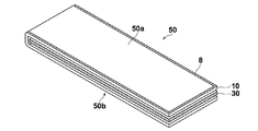
- a long supply gas flow path member 30 is sandwiched between a long acidic gas separation membrane 10 in which the acidic gas separation promoting transport membrane 5 is folded inward to form a leaf 50.
- the acidic gas separation membrane 10 may be divided into two as shown in FIG.
- the adhesive 8 is applied to both ends in the width direction and one end in the longitudinal direction of the one surface 50a of the leaf 50.
- the leaf 50 is placed so that the surface 50a coated with the adhesive 8 is in contact with the surface of the permeate gas flow path member 6 fixed to the permeate gas collecting pipe 12.
- the folded portion of the leaf 50 to which the adhesive 8 is not applied is set to the gas collecting pipe 12 side.
- the end portion on the collecting pipe 12 side along the permeate gas collecting pipe 12 between the acidic gas separation membrane 10 at the beginning of winding of the leaf 50 and the permeating gas flow path member 6 is opened, and the sealing section 7 is opened.
- a flow path P1 (see FIG. 6) in which the acidic gas 22 that has permeated the acidic gas separation membrane 10 flows to the through hole 12A is formed in the region surrounded by.
- the adhesive 38 is applied to the other surface 50b of the leaf 50 placed on the permeating gas channel member 6 at both ends in the width direction and one end in the longitudinal direction of the membrane.
- the permeate gas collecting pipe 12 is wound around the permeate gas collecting pipe 12 so as to cover the through hole 12A with the permeate gas flow path member 6 by rotating the permeate gas collecting pipe 12 in the direction of arrow C.
- the leaf 50 is further wound around the permeating gas channel member 6.
- the adhesive 8 applied to one surface 50a of the leaf permeates the flow path member 6 and the porous support 4 to form the sealing portion 7, and
- the adhesive 38 applied to the other surface 50b of the leaf 50 permeates the permeating gas channel member 6 and the porous support 4 to form the sealing portion 7.
- the adhesive partially spreads inside the laminated body to form the stress buffering portion 9. 7, the sealing portion 7 formed by the adhesive 8 or 38 penetrating into the ends of the collecting tube 12 in the length direction, and the stress buffering portion 9 adjacent to the sealing portion 7. Can be obtained.
- a plurality of leaves 50 and permeate gas flow path members 6 sandwiching the supply gas flow path member 30 with the acidic gas separation membrane 10 folded in two are alternately stacked.
- a plurality of 14 may be overlapped and wound around the permeate gas collecting pipe in a multiple manner.
- the stacks are gradually shifted and stacked as shown in FIG. 10 so as not to increase the level difference after being wound around the collecting pipe.
- a cylindrical winding body is obtained through the above steps, and after trimming both end portions of the obtained cylindrical winding body (end face correction processing), the outermost periphery of the cylindrical winding body is covered with a coating layer 16. By covering and attaching the telescope prevention plates 18 to both ends, the acid gas separation module 100 shown in FIG. 5 is obtained.
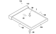
- FIG. 11 is a schematic perspective view showing a flat membrane type acidic gas separation module 110 (hereinafter referred to as a flat membrane type module 110) which is a second embodiment of the acidic gas separation module of the present invention.
- 12 is a cross-sectional view taken along line XII-XII in FIG.
- the flat membrane module 110 includes a permeate gas collecting pipe 112 and a laminate 114 including separation membranes 10 and 10A on both surfaces of the permeate gas flow path member 6. .
- the laminated body 114 is an embodiment of the acidic gas separation laminated body of the present invention, and the porous support 4 in which the porous film 2 and the auxiliary support film 3 are laminated, and the porous support 4 is porous.
- An acidic gas separation membrane 10 comprising an acidic gas separation promoting transport membrane 5 including at least a hydrophilic compound and an acidic gas carrier that reacts with an acidic gas in a raw material gas, disposed on the membrane 2 side;
- a permeating gas flow path member 6 is provided on the auxiliary support membrane 3 side, through which acidic gas that reacts with the acidic gas carrier and permeates the acidic gas separation promoting transport membrane 5 flows.
- another acidic gas separation membrane 10A that faces the acidic gas separation membrane 10 with the permeating gas flow path member 6 interposed therebetween is provided.
- an acidic gas separation membrane 17 having an intermediate layer 15 between the porous support 4 and the facilitated transport membrane 5 may be used instead of the acidic gas separation membranes 10 and 10A.
- the sealing part 7 and the stress buffering part 9 are provided on three sides of the periphery of the laminate 114, and the end part where the sealing part 7 and the stress buffering part 9 are not provided is connected to the permeate gas collecting pipe 112. ing.
- a region surrounded by the sealing portion 7 is a flow path through which the acidic gas 22 that has passed through the acidic gas separation membrane 10 flows to the permeated gas collecting pipe 112.
- the flat membrane module 110 is arranged in a container to which a raw material gas is supplied, and the acidic gas 22 in the raw material gas 20 reacts with the carrier of the facilitated transport film 5 and is taken into the laminated body 114 to be promoted transport film 5 and porous.
- the permeate gas support member 4 passes through the permeate gas passage member 6, is collected in the permeate gas collecting pipe 112, and is collected from a gas outlet (not shown) connected to the permeate gas collecting pipe 112.
- the laminated body 114 since the laminated body 114 includes the stress buffering portion 9 adjacent to the sealing portion 7, it occurs at the boundary between the sealing portion 7 and a portion other than the sealing portion. Damage to the facilitated transport film 5 due to stress concentration can be suppressed.
- Example 1 A PTFE / PP nonwoven fabric (manufactured by GE) was used as a porous support composed of a laminated film of a porous film and an auxiliary support film.
- the thickness of PTFE was about 30 ⁇ m, and the thickness of the PP nonwoven fabric was about 200 ⁇ m.
- This coating composition was coated on a PTFE / PP nonwoven PTFE membrane and dried to form a separation membrane.
- a polypropylene net having a thickness of 0.44 mm is sandwiched between separation membranes whose carbon dioxide separation membrane surface is folded inward. Reinforce with double kapton tape. The folds were firmly folded so that the membrane surface was not damaged, curled, and leaves were formed.
- Adhesive E120HP (made by Henkel Japan Co., Ltd.) made of epoxy resin on the three sides of one side of the perimeter of the permeate gas flow path member made of polypropylene fabric with a thickness of 0.5 mm fixed to a collecting tube with partitions ) Is applied so that one surface is in contact with the permeate gas channel member, and adhesive is applied to three sides of the periphery in the same manner on the other surface of the leaf placed on the channel member. Apply, place a new permeate gas channel member on it, and then repeat the process of placing a new leaf coated with adhesive. From the combination of one leaf and one permeate gas channel member 3 units were stacked and wound around the collecting pipe.
- a spiral separation membrane module was obtained.
- the design membrane area of the spiral-type separation membrane module of Example 1 was 1.2 m 2 .
- the sealing width of the sealing portion was 10 mm, and the width of the stress buffering portion was 30% of the sealing width.
- Examples 2 to 6 were compared in the same manner as in Example 1 except that the sealing width, the ratio of the stress buffering part to the sealing width, and the penetration rate of the adhesive in the stress buffering part were as shown in Table 2 below. Modules of Examples 1 and 2 were respectively produced.
- Example 7 a laminate including an intermediate layer between the porous membrane and the facilitated transport membrane was produced as Example 7.
- an intermediate layer coating solution for forming the intermediate layer silicone-modified epoxy-modified polydimethylsiloxane (KF-102 manufactured by Shin-Etsu Chemical Co., Ltd.) is used.
- As a curing agent 4-isopropyl-4′- manufactured by Tokyo Chemical Industry Co., Ltd. is used.
- This intermediate layer coating solution was applied to the surface of the porous support by a roll-to-roll method, and the intermediate layer coating solution was cured by irradiating ultraviolet rays with a curing device to form an intermediate layer made of a silicone resin on the support. .
- the carbon dioxide separation-promoting transport membrane coating solution composition was coated on the support having the intermediate layer to obtain a laminate for acid gas separation in Example 7.
- the adhesive penetration rate was determined from the adhesive filling area relative to the hole area in the porous membrane, the adhesive penetration rate in the porous membrane was 60% or more, and the adhesive penetration rate in the auxiliary support membrane and the permeating gas channel member was any As a sealing portion, a penetration rate of the adhesive in the porous membrane 2 is less than 60%, and a portion where the adhesive permeates at least the permeating gas channel member is used as a stress buffering portion.
- variety of the stress buffer part were calculated
- the average value of the ratio of the width of the sealing portion and the width of the stress buffer portion to the sealing width for the three cross sections is shown in Table 2 as the ratio of the width of the sealing portion of the module and the width of the stress buffer portion to the sealing width. Yes.
- ⁇ Module factor> The module factor of the module for carbon dioxide separation according to each of the produced examples and comparative examples was evaluated under the following conditions for each of the acidic gas separation module and the acidic gas separation promoting transport membrane on the porous support used in the module. And calculated.
- Ar gas (flow rate 0.9 L / min) was allowed to flow on the permeate side.
- the permeated gas was analyzed with a gas chromatograph, and the CO 2 / H 2 separation factor ( ⁇ ) was calculated.
- a feed gas of H 2 : CO 2 : H 2 O 45: 5: 50 as a supply gas (flow rate 0.32 L / min) is supplied to each carbon dioxide separation membrane at a temperature of 130 ° C. and a total pressure of 301.3 kPa, Ar gas (flow rate: 0.04 L / min) was allowed to flow on the permeate side.
- the permeated gas was analyzed with a gas chromatograph, and the CO 2 / H 2 separation factor ( ⁇ ) was calculated.
- Module factor ⁇ of acid gas separation module / ⁇ of acid gas separation promoting transport membrane on porous support
- the spiral module provided with the laminate for acidic gas separation of the present invention was confirmed to have a module factor of 0.5 or more in both the initial and the first days. Further, in Examples 1 to 3 and 5 to 7 in which the ratio of the width of the stress buffer portion to the sealing width was 50% or less, a more preferable module factor of 0.6 or more could be obtained. This is considered to be because a larger effective area can be secured by suppressing the width of the stress buffer portion. Further, as shown in Example 7, by having the intermediate layer, it was possible to raise the stress buffering ability of the laminate while maintaining gas permeability, and it was possible to show a high module factor from the initial performance.
- Comparative Example 1 is a module in which the ratio of the width of the stress buffer portion to the sealing width is 0%, that is, a module that does not have a stress buffer portion. could not.
- Comparative Example 2 had a small sealing width and could not be sufficiently sealed, and after one day, the part that was initially sealed was peeled off, and the module factor could not be measured.
- the module of Example 1 also had a high module factor in evaluation under high pressure (2.0 MPa).
Landscapes
- Chemical & Material Sciences (AREA)
- Chemical Kinetics & Catalysis (AREA)
- Engineering & Computer Science (AREA)
- Analytical Chemistry (AREA)
- General Chemical & Material Sciences (AREA)
- Oil, Petroleum & Natural Gas (AREA)
- Dispersion Chemistry (AREA)
- Inorganic Chemistry (AREA)
- Manufacturing & Machinery (AREA)
- Separation Using Semi-Permeable Membranes (AREA)
Abstract
【課題】欠陥発生を抑制することができる酸性ガス分離用積層体および酸性ガス分離用モジュールを提供する。 【解決手段】多孔質膜(2)と補助支持膜(3)とが積層されてなる多孔質支持体(4)と、酸性ガス分離促進輸送膜(5)と、透過ガス流路用部材(6)を備えた酸性ガス分離用積層体(1)に、周縁に5mm以上の幅で多孔質膜(2)、補助支持膜(3)およびガス流路用部材(6)の積層方向に接着剤(8)が染み込み率60%以上で浸透して形成された封止部(7)と、封止部(7)に隣接し、少なくとも多孔質膜(2)における接着剤(8)の染み込み率が60%未満であり、かつ、少なくともガス流路用部材(6)に接着剤(8)が浸透して形成された応力緩衝部(9)を備えるものとする。
Description
本発明は、酸性ガス分離機能を有する酸性ガス分離用積層体およびその積層体を備えた酸性ガス分離用モジュールに関するものである。
近年、混合ガス中の酸性ガスを選択的に分離する技術の開発が進んでいる。例えば、酸性ガスを選択的に透過する酸性ガス分離膜によって、原料ガスから酸性ガスを分離する酸性ガス分離用モジュールの開発が進んでいる。
分離膜は、分離膜中のキャリアによって酸性ガスが膜の反対側に輸送される、いわゆる促進輸送膜と、膜に対する酸性ガスと分離対象物質の溶解性、および膜中の拡散性の差を利用して分離を行ういわゆる溶解拡散膜に大別される。
そのような分離膜を備えた分離膜モジュールとしては、スパイラル型、平膜型、中空糸型など各種形式の膜モジュールが用いられている。例えば、特許文献1には、分離膜、供給側流路用部材および透過側流路用部材を中心管の回りに巻回したスパイラル型膜モジュール、特許文献2には、平膜型膜モジュールが開示されている。
スパイラル型膜モジュールは、一般的に分離膜を二つ折りにした間に供給側流路用部材を配置したリーフと、透過側流路用部材とを交互に積み重ね、供給側流体と透過側流体の混合を防ぐため、分離膜と透過側流路用部材との積層体周縁部のうちの三辺に接着剤を塗布して分離膜ユニットを作製し、このユニットの単数または複数を中心管(流体集合管)の周囲にスパイラル状に巻き付けて、得られた円筒状巻回体の両端部をトリミング(端面修正加工)して製造される。
平膜型モジュールは、透過側流路用部材の片面もしくは両面に分離膜を配置し、やはり、その積層体周縁部のうちの三辺に、接着剤を塗布して分離膜ユニットを作製し、接着剤が塗布されていない1辺が流体集合管に接合されてなる。
いずれのモジュールにおいても、接着剤により形成される封止部は、供給側流体と透過側流体の混合を防ぎ、分離性能を上げる観点から極めて重要である。
平膜型モジュールは、透過側流路用部材の片面もしくは両面に分離膜を配置し、やはり、その積層体周縁部のうちの三辺に、接着剤を塗布して分離膜ユニットを作製し、接着剤が塗布されていない1辺が流体集合管に接合されてなる。
いずれのモジュールにおいても、接着剤により形成される封止部は、供給側流体と透過側流体の混合を防ぎ、分離性能を上げる観点から極めて重要である。
この封止部による封止精度が十分でないと分離性能が低下することから、精度よい封止方法や、接着剤の充填率や接着幅についての検討もいくつかなされている(特許文献3、4等)。
分離対象物質が気体(ガス)の場合には、運転時において液体の場合よりもはるかに漏れやすい上に、促進輸送膜を備えた酸性ガス分離用モジュールでは、水蒸気を含有するような原料ガスから酸性ガスを分離するため、分離膜の粘性が低下する。また、供給ガスは大気圧以上の圧力を有しており、供給ガス側と透過ガス側に差圧が生じ、その差圧が粘性の低下した分離膜にかかることとなる。さらに、接着剤で封止した三辺部と、それ以外の部分とでは、力学的強度が異なるため、両者の境界に応力集中が起こりやすい。境界に大きく応力がかかることにより、分離膜に欠陥が生じてしまうことが散見される。
本発明は、分離膜における欠陥の発生を抑制することができる、酸性ガス分離用モジュールに適用される酸性ガス分離積層体およびその積層体を備えた酸性ガス分離用モジュールを提供することを目的とするものである。
本発明の酸性ガス分離用積層体は、多孔質膜と補助支持膜とが積層されてなる多孔質支持体と、
多孔質支持体の多孔質膜側に配された、原料ガス中の酸性ガスを分離する機能を有する酸性ガス分離促進輸送膜と、
多孔質支持体の補助支持膜側に配された、酸性ガス分離促進輸送膜を透過した酸性ガスが流れる透過ガス流路用部材とからなる酸性ガス分離用積層体であって、
積層体の周縁に5mm以上の幅で多孔質膜に接着剤が染み込み率60%以上で浸透し、かつ、補助支持膜およびガス流路用部材に接着剤がそれぞれ染み込み率60%以上で浸透して形成された封止部と、
封止部に隣接し、少なくとも多孔質膜における接着剤の染み込み率が60%未満であり、かつ、補助支持膜およびガス流路用部材に接着剤が浸透して形成された応力緩衝部とを備えていることを特徴とする。
多孔質支持体の多孔質膜側に配された、原料ガス中の酸性ガスを分離する機能を有する酸性ガス分離促進輸送膜と、
多孔質支持体の補助支持膜側に配された、酸性ガス分離促進輸送膜を透過した酸性ガスが流れる透過ガス流路用部材とからなる酸性ガス分離用積層体であって、
積層体の周縁に5mm以上の幅で多孔質膜に接着剤が染み込み率60%以上で浸透し、かつ、補助支持膜およびガス流路用部材に接着剤がそれぞれ染み込み率60%以上で浸透して形成された封止部と、
封止部に隣接し、少なくとも多孔質膜における接着剤の染み込み率が60%未満であり、かつ、補助支持膜およびガス流路用部材に接着剤が浸透して形成された応力緩衝部とを備えていることを特徴とする。
封止部においては、補助支持膜およびガス流路用部材への接着剤の染み込み率が80%以上であることが好ましい。
応力緩衝部の幅が封止部の幅の0.1%以上、50%以下であることが好ましい。
応力緩衝部の幅は封止部の幅の40%以下であることがより好ましい。
応力緩衝部の幅は封止部の幅の40%以下であることがより好ましい。
なお、封止部は積層体の周縁の全てに設けられている必要はなく、周縁のうち封止する必要のある部分に設けられていればよい。
ここで、「接着剤の染み込み率」は、多孔質膜、補助支持膜およびガス流路用部材のそれぞれにおける空隙(孔)に対する接着剤の充填率を意味する。
接着剤の染み込み率は、SEM(走査型電子顕微鏡)、または、光学顕微鏡で、接着剤塗布後の積層体の断面(封止幅方向に平行な断面)を3視野観察し、接着剤塗布後の各膜、部材の穴の面積に対する、穴に充填されている接着剤の面積の割合を画像処理により求めて得るものとする。ここで3視野とは、例えば、封止部が周縁の3辺に設けられている場合、辺毎に3視野観察することをいう。また、1視野中には1つの封止部のみとする。このとき、積層体の端部から染み込み率が各膜および部材においていずれも60%以上となっている範囲を封止部と特定する。そして、封止部よりも積層体内方(端部と逆方向)の接着剤が染み込んでいる領域を応力緩衝部と特定する。なお、本発明においては、封止部における補助支持膜およびガス流路用部材への接着剤の染み込み率は多孔質膜への接着剤染み込み率と同等以上であると想定している。
ここで、「接着剤の染み込み率」は、多孔質膜、補助支持膜およびガス流路用部材のそれぞれにおける空隙(孔)に対する接着剤の充填率を意味する。
接着剤の染み込み率は、SEM(走査型電子顕微鏡)、または、光学顕微鏡で、接着剤塗布後の積層体の断面(封止幅方向に平行な断面)を3視野観察し、接着剤塗布後の各膜、部材の穴の面積に対する、穴に充填されている接着剤の面積の割合を画像処理により求めて得るものとする。ここで3視野とは、例えば、封止部が周縁の3辺に設けられている場合、辺毎に3視野観察することをいう。また、1視野中には1つの封止部のみとする。このとき、積層体の端部から染み込み率が各膜および部材においていずれも60%以上となっている範囲を封止部と特定する。そして、封止部よりも積層体内方(端部と逆方向)の接着剤が染み込んでいる領域を応力緩衝部と特定する。なお、本発明においては、封止部における補助支持膜およびガス流路用部材への接着剤の染み込み率は多孔質膜への接着剤染み込み率と同等以上であると想定している。
積層体の端部から0.01mm幅毎に多孔質膜、補助支持膜および透過ガス流路用部材の各部における孔の面積に対する接着剤の充填面積から接着剤の染み込み率を求め、端部から多孔質膜、補助支持膜およびガス流路用部材における接着剤染み込み率が60%以上を満たすもっとも遠い位置までを封止部と特定し、端部からその位置までの距離を封止部の幅と定義する。そして、その封止部の端から多孔質膜における接着剤染み込み率が0%となる直前の位置までを応力緩衝部と特定し、その封止部の端から接着剤染み込み率が0%になる直前の位置までの距離を応力緩衝部の幅と定義する。
すなわち、応力緩衝部は、少なくとも多孔質膜における接着剤の染み込み率が60%未満であり、補助支持膜および透過側ガス流路用部材に接着剤が浸透している領域であればよく、補助支持膜および透過側ガス流路用部材の接着剤染み込み率は60%以上であっても、60%未満であってもよい。
すなわち、応力緩衝部は、少なくとも多孔質膜における接着剤の染み込み率が60%未満であり、補助支持膜および透過側ガス流路用部材に接着剤が浸透している領域であればよく、補助支持膜および透過側ガス流路用部材の接着剤染み込み率は60%以上であっても、60%未満であってもよい。
前述の接着剤塗布後の積層体について封止部が設けられている各辺の封止部の幅、応力緩衝部の幅を求め、その平均値を積層体における封止部の幅および応力緩衝部の幅とする。なお、封止部の幅は積層体の面方向に不均一であってもよいが、どの場所においても5mm以上であることを要する。また、積層方向において接着剤の染み込み率は一様でなくてもよいが、少なくとも端部から5mm以上の範囲においては多孔質膜、補助支持膜および透過ガス流路用部材のすべてにおいて充填率が60%以上を満たすものである。
上記封止部の幅は5mm以上であればよいが、大きくなればなるほど分離有効面積が小さくなるため、70mm以下とすることが好ましい。
多孔質膜がフッ素系樹脂材料からなるものであることが好ましい。
多孔質膜はポリテトラフルオロエチレン(PTFE)からなるものであることが特に好ましい。
接着剤はエポキシ系樹脂からなるものであることが好ましい。
本発明の酸性ガス分離用積層体においては、多孔質膜と酸性ガス分離促進輸送膜との間に中間層を有することが好ましい。
上記中間層はシリコーン樹脂であることが好ましい。
本発明の酸性ガス分離用モジュールは、透過ガス集合管と、本発明の酸性ガス分離用積層体とを備え、積層体の封止部が形成されていない端部の透過ガス流路用部材が、透過ガス集合管に接続されてなることを特徴とするものである。
本発明の酸性ガス分離用モジュールは、スパイラル型モジュールであってもよいし、平膜型モジュールであってもよい。
本発明の酸性ガス分離用積層体は、多孔質膜と補助支持膜とが積層されてなる多孔質支持体と、酸性ガス分離促進輸送膜と、透過ガス流路用部材とを備え、多孔質膜に接着剤が染み込み率60%以上で浸透し、かつ、補助支持膜およびガス流路用部材に接着剤がそれぞれ染み込み率60%以上で浸透して形成された封止部に隣接して、少なくとも多孔質膜における接着剤の染み込み率が60%未満であり、補助支持膜および透過ガス流路用部材に接着剤が浸透して形成された応力緩衝部を備えているので、酸性ガス分離用モジュールに組み込まれて使用に供される際に、接着剤が染み込んだ領域とそうでない領域の力学的強度差によりその境界に生じる応力集中を緩和させることができ、酸性ガス分離促進輸送層に欠陥が生じるのを抑制することができる。
以下、図面を参照して本発明の実施形態を説明する。なお、以下の図面において、同一又は対応する機能を有する部材(構成要素)には同じ符号を付して適宜説明を省略する。
[酸性ガス分離用積層体]
図1Aは、本発明の実施形態にかかる酸性ガス分離用積層体1の積層構成を示す模式的斜視図であり、図1Bは積層体1の端部の拡大断面図である。
図1Aは、本発明の実施形態にかかる酸性ガス分離用積層体1の積層構成を示す模式的斜視図であり、図1Bは積層体1の端部の拡大断面図である。
図1Aに示すように、本実施形態の酸性ガス分離用積層体1は、多孔質膜2と補助支持膜3とが積層されてなる多孔質支持体4と、多孔質支持体4の多孔質膜2側に配された、原料ガス(供給ガス)中の酸性ガスと直接または間接的に反応するキャリアおよびキャリアを担持する親水性化合物を含有する酸性ガス分離促進輸送膜5とからなるガス分離複合膜(以下において、ガス分離膜)10と、多孔質支持体4の補助支持膜3側に配された、分離促進輸送膜5および多孔質支持体4を透過した酸性ガスが流れる透過ガス流路用部材6とを備えている。
そして、矩形状の積層体1の周縁(四辺)のうち一辺を除く三辺において、多孔質支持体4と透過ガス流路用部材6とにガスの流入を封止するための封止部7と封止部7に隣接して応力緩衝部9とが設けられている。封止部7は、分離膜10と流路用部材6とを接着すると共に、供給ガスと透過ガスとの混合を防ぐ機能を有する。また、応力緩衝部9は、促進輸送膜5に欠陥が生じるのを抑制する機能を有する。
封止部7は多孔質支持体4と流路用部材6に接着剤8が染み込んで構成される部分であり、積層方向において、多孔質支持体4の多孔質膜2においては60%以上の染み込み率で接着剤8が染み込んでおり、補助支持膜3および流路用部材6においては、60%以上の染み込み率で接着剤8が染み込んでいる部分である。封止部7の幅x(以下において、封止幅x)は、積層体1の端部から5mm以上である。なお、封止部7においては、補助支持膜3および流路用部材6における接着剤8の染み込み率は80%以上、さらには90%以上であることが好ましい。
封止幅xを5mm以上とすることにより、十分なガス封止機能を担保することができる。接着剤は必ずしも均一な幅で拡がらないため、図1Cに模式図を示すように、封止幅xおよび応力緩衝部9の幅aは積層体1の面方向の各箇所において変化していてもよく、最も小さい封止幅が5mm以上であればよい。一方で、封止幅xが大きくなると、ガス分離のための有効領域が狭くなるため、全域に亘り封止幅xは5mm以上であれば長すぎない方がよい。封止幅xは5mm~70mmであることが好ましく、10mm~50mmであることが特に好ましい。
封止幅xを5mm以上とすることにより、十分なガス封止機能を担保することができる。接着剤は必ずしも均一な幅で拡がらないため、図1Cに模式図を示すように、封止幅xおよび応力緩衝部9の幅aは積層体1の面方向の各箇所において変化していてもよく、最も小さい封止幅が5mm以上であればよい。一方で、封止幅xが大きくなると、ガス分離のための有効領域が狭くなるため、全域に亘り封止幅xは5mm以上であれば長すぎない方がよい。封止幅xは5mm~70mmであることが好ましく、10mm~50mmであることが特に好ましい。
応力緩衝部9は、少なくとも多孔質膜2における接着剤8の染み込み率が60%未満となっている部分である。この応力緩衝部9において、補助支持膜3および流路用部材6においては、接着剤の染み込み率は60%以上であっても、60%未満であってもよいが、少なくとも流路用部材6の染み込み率は10%以上であることが好ましい。また、応力緩衝部9においては、流路用部材6における染み込み率が多孔質膜2における染み込み率よりも大きいことが好ましい。この応力緩衝部9は、促進輸送膜5に欠陥が生じるのを抑制する機能を有するが、流路のロス部でもある。すなわち、応力緩衝部9の領域が大きくなるほど、透過ガスの流路が失われるため、応力緩衝部9の幅aは短いほど好ましい。この幅aを封止幅xの半分以下(50%以下)とすることにより、応力による膜欠陥を抑制することができると共に、流路ロスを小さくすることができる。応力緩衝部9の幅は封止部の幅の40%以下であることがより好ましい。
本例では、積層体1は矩形状であり、その周縁のうち一辺を除く三辺に封止部7およびそれに隣接した応力緩衝部9が形成されている。なお、積層体1の形状および封止部7が形成される領域は、積層膜が適用されるモジュール構成に応じて適宜設定することができる。
本積層体1は、酸性ガスを含む原料ガス(供給ガス)から酸性ガスを分離する分離膜モジュールに適用されるものであるが、特に、供給ガスが水蒸気を含むものである場合に好適である。そのような分離膜モジュールに適用された場合、促進輸送膜5は、水分を吸収することによりその粘性が低下する。このとき、供給ガスによる圧力(供給ガスと透過ガスとの差圧)Sにより促進輸送膜5は多孔質膜側に押し付けられ、その際に、接着剤が染み込んでいる領域と接着剤が染み込んでいない領域とで力学的な強度(剛性)が異なるために、両領域の境界において応力集中が生じ、境界の促進輸送膜5に欠陥が生じる恐れがある。本発明の実施形態である積層体1は、図1Bに拡大図を示すように、封止部7に隣接して応力緩衝部9を備えており、この応力緩衝部9による応力集中を緩和する機能により促進輸送膜5における欠陥の発生を抑制することができる。モジュールによるガス分離を実行する際には、供給ガスと透過ガスとの圧力差(差圧)により通常は供給ガス側から促進輸送膜5に所定の圧力Sがかかる。このとき、接着剤の染み込み率(染み込みの有無を含む)により、促進輸送膜5を支持する多孔質支持体4および流路用部材6の剛性が異なるため、剛性が大きく異なる領域間の境界位置の促進輸送膜5の、例えば図1Bの矢印Pで示す部分に応力集中が生じる。応力緩衝部9がない場合、封止部7と全く接着剤が浸透していない領域とが隣接するため、境界での応力集中が大きくなり促進輸送膜5に欠陥が生じやすいが、応力緩衝部9を備えることにより、段階的に剛性を変化させることができるため、応力集中を緩和することが可能となる。
なお、図1Aや図1Bにおいては、応力緩衝部9の多孔質膜2には接着剤8が全く染み込んでいない状態を示しているが、図1Dに示すように、応力緩衝部9の多孔質膜2において染み込み領域9aが徐々に変化していてもよい。また、補助支持膜3や流路用部材6においても染み込み領域は積層方向に端部からの距離が変化していてもよい。
なお、接着剤の染み込み率は、図1Dに示すように、切断面において端部から0.01mm幅の領域毎に、例えば、図1D中一点鎖線で挟まれた領域ci毎に、画像処理によって、各層(多孔質膜2、補助支持膜3および流路用部材6)の孔の面積に対する接着剤が充填されている面積の比を求めて算出する。また、封止部の幅および応力緩衝部の幅は、接着剤の染み込み率から求める。端部から0.01mm幅の領域(以下において、測定単位領域)毎に多孔質膜における接着剤染み込み率を求め、多孔質膜における接着剤染み込み率60%以上を満たす測定単位領域のうち端部からもっとも遠い測定単位領域(図1Dにおいては、領域cn)までを含む領域が封止部7であり、積層体の端部からその測定単位領域cnの積層体端部から遠い側の端9bまでの距離が封止部7の幅である。なお、接着剤は積層体の端部側から積層体の面内内方に向けてその充填率は小さくなるので、領域cnの面内方向に隣接する領域cn+1で初めて接着剤染み込み率は60%未満となる。そして、封止部7の端9bから測定単位領域において多孔質膜における接着剤染み込み率が0%となる領域czの直前の測定単位領域cz-1までを含む領域が応力緩衝部9であり、封止部7の端9bから接着剤染み込み率が0%になる直前の領域cz-1の端9cまでの距離が応力緩衝部9の幅である。なお、図1Cに示したように、接着剤の染み込み領域は封止部が形成される面方向位置毎に大きく異なる場合があるため、封止部の幅、応力緩衝部の幅は、複数箇所(例えば3箇所)の断面において得られた値の平均値とする。
<ガス分離膜>
ガス分離膜10は、酸性ガス分離促進輸送膜5と、促進輸送膜5を支持し、透過ガス流路用部材6側に設けられた多孔質支持体4とを有している。
ガス分離膜10は、酸性ガス分離促進輸送膜5と、促進輸送膜5を支持し、透過ガス流路用部材6側に設けられた多孔質支持体4とを有している。
(酸性ガス分離促進輸送膜)
酸性ガス分離促進輸送膜5は、原料ガス中の酸性ガスと直接もしくは間接的に反応するキャリアとキャリアを担持する親水性化合物を少なくとも含有し、原料ガスから酸性ガスを選択的に透過させる機能を有している。
促進輸送膜5は一般的に溶解拡散膜よりも耐熱性を有していることから、例えば100℃~200℃の温度条件下でも酸性ガスを選択的に透過させることができる。また、原料ガスに水蒸気が含まれていても、当該水蒸気を親水性化合物が吸湿して当該親水性化合物を含有する促進輸送膜が水分を保持することで、さらにキャリアが輸送し易くなるので、溶解拡散膜を用いる場合に比べて分離効率が高まる。
酸性ガス分離促進輸送膜5は、原料ガス中の酸性ガスと直接もしくは間接的に反応するキャリアとキャリアを担持する親水性化合物を少なくとも含有し、原料ガスから酸性ガスを選択的に透過させる機能を有している。
促進輸送膜5は一般的に溶解拡散膜よりも耐熱性を有していることから、例えば100℃~200℃の温度条件下でも酸性ガスを選択的に透過させることができる。また、原料ガスに水蒸気が含まれていても、当該水蒸気を親水性化合物が吸湿して当該親水性化合物を含有する促進輸送膜が水分を保持することで、さらにキャリアが輸送し易くなるので、溶解拡散膜を用いる場合に比べて分離効率が高まる。
促進輸送膜5の膜面積は、特に限定されないが、0.01m2以上1000m2以下であることが好ましく、0.02m2以上750m2以下であることがより好ましく、0.025m2以上500m2以下であることがさらにより好ましい。さらに、上記膜面積は、実用的な観点から、1m2以上100m2以下であることが好ましい。
各下限値以上とすることで、膜面積に対して効率よく酸性ガスを分離することができる。また、各上限値以下とすることで、加工性が容易となる。
各下限値以上とすることで、膜面積に対して効率よく酸性ガスを分離することができる。また、各上限値以下とすることで、加工性が容易となる。
促進輸送膜5の厚さは特に限定されないが、1~200μmであることが好ましく、2~175μmであることがより好ましい。このような範囲の厚さにすることにより、十分なガス透過性と分離選択性とを実現することができ好ましい。
(親水性化合物)
親水性化合物としては、親水性ポリマーが挙げられる。親水性ポリマーはバインダーとして機能するものであり、水を保持して酸性ガスキャリアによる酸性ガスの分離機能を発揮させる。親水性化合物は、水に溶けて、もしくは、水に分散して塗布液を形成することができるとともに、酸性ガス分離層が高い親水性(保湿性)を有する観点から、親水性が高いものが好ましく、親水性化合物自体の質量に対して、5倍以上1000倍以下の質量の水を吸収するものであるものが好ましい。
親水性化合物としては、親水性ポリマーが挙げられる。親水性ポリマーはバインダーとして機能するものであり、水を保持して酸性ガスキャリアによる酸性ガスの分離機能を発揮させる。親水性化合物は、水に溶けて、もしくは、水に分散して塗布液を形成することができるとともに、酸性ガス分離層が高い親水性(保湿性)を有する観点から、親水性が高いものが好ましく、親水性化合物自体の質量に対して、5倍以上1000倍以下の質量の水を吸収するものであるものが好ましい。
親水性ポリマーとしては、親水性、製膜性、強度などの観点から、例えば、ポリビニルアルコール-ポリアクリル酸塩、およびポリビニルアルコール-ポリアクリル酸(PVA-PAA)共重合体、ポリビニルアルコール、ポリアクリル酸、ポリアクリル酸塩、ポリビニルブチラール、ポリ-N-ビニルピロリドン、ポリ-N-ビニルアセトアミド、ポリアクリルアミドが好適であり、特にPVA-PAA共重合体が好ましい。PVA-PAA共重合体は、吸水能が高い上に、高吸水時のハイドロゲル状態での強度が大きい。PVA-PAA共重合体におけるポリアクリル酸塩の含有率は、例えば5モル%以上95モル%以下が好ましく、好ましくは30モル%以上70モル%以下がさらに好ましい。ポリアクリル酸塩としては、ナトリウム塩、カリウム塩等のアルカリ金属塩の他、アンモニウム塩や有機アンモニウム塩等が挙げられる。
市販されているPVA-PAA共重合体として、例えば、クラストマーAP20(クラレ社製)が挙げられる。
市販されているPVA-PAA共重合体として、例えば、クラストマーAP20(クラレ社製)が挙げられる。
(酸性ガスキャリア)
酸性ガスキャリアは、酸性ガス(例えば炭酸ガス)と親和性を有し、かつ、塩基性を示す各種の水溶性の化合物であり、間接的に酸性ガスと反応するもの、あるいは、そのもの自体が直接的に酸性ガスと反応するものである。間接的に酸性ガスと反応するとは、例えば、供給ガス中に含まれる他のガスと反応して塩基性化合物を生成し、その塩基性化合物と酸性ガスが反応することなどが挙げられる。この種の酸性ガスキャリアとしては、具体的には、スチーム(水蒸気)と接触してOH-を放出し、そのOH-がCO2と反応することで膜中に選択的にCO2を取り込むことができるようなアルカリ金属、およびアルカリ金属化合物が挙げられる。
また、直接的に酸性ガスと反応する酸性ガスキャリアとしては、そのもの自体が塩基性であるような、例えば、窒素含有化合物や硫黄酸化物などが挙げられる。
酸性ガスキャリアは、酸性ガス(例えば炭酸ガス)と親和性を有し、かつ、塩基性を示す各種の水溶性の化合物であり、間接的に酸性ガスと反応するもの、あるいは、そのもの自体が直接的に酸性ガスと反応するものである。間接的に酸性ガスと反応するとは、例えば、供給ガス中に含まれる他のガスと反応して塩基性化合物を生成し、その塩基性化合物と酸性ガスが反応することなどが挙げられる。この種の酸性ガスキャリアとしては、具体的には、スチーム(水蒸気)と接触してOH-を放出し、そのOH-がCO2と反応することで膜中に選択的にCO2を取り込むことができるようなアルカリ金属、およびアルカリ金属化合物が挙げられる。
また、直接的に酸性ガスと反応する酸性ガスキャリアとしては、そのもの自体が塩基性であるような、例えば、窒素含有化合物や硫黄酸化物などが挙げられる。
アルカリ金属化合物としては、例えば、アルカリ金属炭酸塩、アルカリ金属重炭酸塩およびアルカリ金属水酸化物からなる群から選択される少なくとも1種、これを含む水溶液にアルカリ金属イオンと錯体を形成する多座配位子を添加した水溶液が挙げられる。
なお、本明細書において、アルカリ金属、あるいはアルカリ金属化合物とは、そのもののほか、その塩およびそのイオンを含む意味で用いる。
なお、本明細書において、アルカリ金属、あるいはアルカリ金属化合物とは、そのもののほか、その塩およびそのイオンを含む意味で用いる。
アルカリ金属炭酸塩としては、例えば、炭酸リチウム、炭酸ナトリウム、炭酸カリウム、炭酸ルビジウム、および炭酸セシウムなどが挙げられる。
アルカリ金属重炭酸塩としては、例えば、炭酸水素リチウム、炭酸水素ナトリウム、炭酸水素カリウム、炭酸水素ルビジウム、および炭酸水素セシウムなどが挙げられる。
アルカリ金属水酸化物としては、例えば、水酸化リチウム、水酸化ナトリウム、水酸化カリウム、水酸化ルビジウム、および水酸化セシウムなどが挙げられる。
これらの中でも、アルカリ金属炭酸塩が好ましく、また、酸性ガスとの親和性がよいという観点から、水に対する溶解度の高いカリウム、ルビジウム、およびセシウムをアルカリ金属元素として含む化合物が好ましい。
アルカリ金属重炭酸塩としては、例えば、炭酸水素リチウム、炭酸水素ナトリウム、炭酸水素カリウム、炭酸水素ルビジウム、および炭酸水素セシウムなどが挙げられる。
アルカリ金属水酸化物としては、例えば、水酸化リチウム、水酸化ナトリウム、水酸化カリウム、水酸化ルビジウム、および水酸化セシウムなどが挙げられる。
これらの中でも、アルカリ金属炭酸塩が好ましく、また、酸性ガスとの親和性がよいという観点から、水に対する溶解度の高いカリウム、ルビジウム、およびセシウムをアルカリ金属元素として含む化合物が好ましい。
本実施形態では、吸湿性の促進輸送膜を用いているため、製造時に吸湿した水分で促進輸送膜がゲル状となり促進輸送膜が製造時に膜同士や他の部材にくっつくという現象(ブロッキング)が生じ易い。このブロッキングが起こると、促進輸送膜を剥がす際に促進輸送膜がそのくっつきにより欠陥を生じてしまい、結果としてガス漏れが生じ得る。したがって、本実施形態では、ブロッキング抑止を図る方が好ましい。
そこで、本実施形態では、キャリアは、アルカリ金属化合物を2種以上含むことが好ましい。2種以上のキャリアとすることで、膜中の同種のキャリアを距離的に離すことができ、ブロッキングの不均一さを生み出してブロッキング抑止を図ることができるからである。
さらに、キャリアは、潮解性を有する第1アルカリ金属化合物と、当該第1アルカリ金属化合物よりも潮解性が低く比重が小さい第2アルカリ金属化合物とを含むことがより好ましい。具体的に、第1アルカリ金属化合物として炭酸セシウムが挙げられ、第2アルカリ金属化合物として炭酸カリウムが挙げられる。
キャリアが第1アルカリ金属化合物と第2アルカリ金属化合物を含むことで、比重が小さい第2アルカリ金属化合物が促進輸送膜の膜面側に配置され(つまり促進輸送膜の表面側に偏在して配置され)、比重が大きい第1アルカリ金属化合物が促進輸送膜の膜内側に配置される(つまり促進輸送膜の多孔質支持体側に偏在して配置される)。そして、膜面側に配置される第2アルカリ金属化合物は第1アルカリ金属化合物よりも潮解性が低いため、膜面側に第1アルカリ金属化合物が配置される場合に比べて、膜面がべたつかず、ブロッキングを抑止することができる。また、膜内側には潮解性の高い第1アルカリ金属化合物が配置されるので、単に第2アルカリ金属化合物が膜全体に配置される場合に比べて、ブロッキングを抑止するとともに、炭酸ガスの分離効率を高めることができる。
さらに、キャリアは、潮解性を有する第1アルカリ金属化合物と、当該第1アルカリ金属化合物よりも潮解性が低く比重が小さい第2アルカリ金属化合物とを含むことがより好ましい。具体的に、第1アルカリ金属化合物として炭酸セシウムが挙げられ、第2アルカリ金属化合物として炭酸カリウムが挙げられる。
キャリアが第1アルカリ金属化合物と第2アルカリ金属化合物を含むことで、比重が小さい第2アルカリ金属化合物が促進輸送膜の膜面側に配置され(つまり促進輸送膜の表面側に偏在して配置され)、比重が大きい第1アルカリ金属化合物が促進輸送膜の膜内側に配置される(つまり促進輸送膜の多孔質支持体側に偏在して配置される)。そして、膜面側に配置される第2アルカリ金属化合物は第1アルカリ金属化合物よりも潮解性が低いため、膜面側に第1アルカリ金属化合物が配置される場合に比べて、膜面がべたつかず、ブロッキングを抑止することができる。また、膜内側には潮解性の高い第1アルカリ金属化合物が配置されるので、単に第2アルカリ金属化合物が膜全体に配置される場合に比べて、ブロッキングを抑止するとともに、炭酸ガスの分離効率を高めることができる。
具体的には、キャリアとして2種以上のアルカリ金属化合物(第1および第2アルカリ金属化合物)を適用した場合、促進輸送膜5は多孔質支持体4とは反対側の表面側の第2層とその下方で多孔質支持体4側の第1層とからなる。そして、促進輸送膜5は全体において親水性化合物(親水性ポリマー)で構成されているが、その中で、第2層には主に潮解性が低く比重が小さい第2アルカリ金属化合物が含有されている。第1層には主に潮解性を有する第1アルカリ金属化合物が存在する。なお、第2層の厚さは特に限定されないが、十分な潮解性の抑制機能を発揮させるために、0.01~150μmであることが好ましく、0.1~100μmであることがより好ましい。
例えば、促進輸送膜5において、表面側に第2アルカリ金属化合物を含む第2層が偏在し、その下方に第1アルカリ金属化合物を含む第1層が広がる形態とすることができるが、これに限定されるものではない。例えば、両層の界面は明確でなくてもよく両者の濃度が傾斜的に変化する状態で区分されていてもよい。また、その界面は平面的でなく、緩やかな起伏を有する状態であってもよい。
潮解性が低く比重が小さい第2アルカリ金属化合物を含有する第2層の作用により、膜の潮解性が抑制される。このように第2アルカリ金属化合物が偏在する理由について述べると、2種以上のアルカリ金属の比重の差によるものと解される。すなわち、2種以上のアルカリ金属のうち1種を低比重にすることで、その製膜時に塗布液中で比重の軽いものを上方(表面側)に局在させることが可能となる。そして、膜内部の第1層に含有する潮解性を有する第1アルカリ金属化合物のもつ二酸化炭素等の高い輸送力を維持しながら、第2層の膜表面では第2アルカリ金属化合物のもつより結晶化しやすい性質等により結露等を防ぐことができる。これにより、ブロッキングを抑止するとともに、炭酸ガスの分離効率を高めることができる。
なお、第2アルカリ金属化合物はブロッキング抑止のため膜面側にのみあればよいので、第2アルカリ金属化合物は第1アルカリ金属化合物よりも少量含まれていることが好ましい。これにより、潮解性の高い第1アルカリ金属化合物は膜全体において相対的に量が多くなり、炭酸ガスの分離効率をより高めることができる。
第2アルカリ金属化合物と第1アルカリ金属化合物との比率は特に限定されないが、第2アルカリ金属化合物100質量部に対して、第1アルカリ金属化合物は50質量部以上であることが好ましく、100質量部以上であることがより好ましい。上限値としては、100000質量部以下であることが好ましく、80000質量部以下であることがより好ましい。当該両者の比率をこの範囲で調整することにより、ブロッキング性とハンドリング性とを高いレベルで両立することができる。
ここで、2種以上のアルカリ金属化合物の種類数とは、アルカリ金属の種類によって定まるものとし、対イオンが異なっていても1種とは数えないこととする。つまり、炭酸カリウムと水酸化カリウムとが併用されていても1種と数えることとする。
2種以上のアルカリ金属化合物の組合せとしては、下記表1に記載のものが好ましい。なお、表1においては、アルカリ金属の名称でアルカリ金属化合物を表示しているが、その塩やイオンであってもよい。

促進輸送膜中における酸性ガスキャリア全体として含有量は、親水性化合物の量との比率、酸性ガスキャリアの種類にもよるが、塗布前の塩析を防ぐとともに、酸性ガスの分離機能を確実に発揮させるため、0.3質量%~30質量%であることが好ましく、さらに0.5~25質量%であることがより好ましく、さらに1~20質量%であることが特に好ましい。
キャリアとして、2種以上のアルカリ金属化合物を適用する場合、2種以上のアルカリ金属化合物の含有量を、膜の主成分である親水性化合物および2種以上のアルカリ金属化合物等の固形分の合計質量との関係で示すと、2種以上のアルカリ金属化合物の質量比率が25質量%以上85質量%以下であることが好ましく、30質量%以上80質量%以下であることがより好ましい。この量を上記の範囲とすることで、ガス分離機能を十分に発揮させることができる。
2種以上のアルカリ金属化合物のうち、第1アルカリ金属化合物よりも潮解性が低く比重が小さい第2アルカリ金属化合物(促進輸送膜5の表面側に偏在したアルカリ金属化合物)ついては、親水性化合物および2種以上のアルカリ金属化合物等の固形分の合計質量(典型的には乾燥後の分離層の総質量)に対して、0.01質量%以上であることが好ましく、0.02質量%以上であることがより好ましい。上限は特にないが、10質量%以下であることが好ましく、7.5質量%以下であることがより好ましい。この量が少なすぎるとブロッキングを防げないことがあり、多すぎるとハンドリングできないことがある。
窒素含有化合物としては、アンモニア、アンモニウム塩、各種直鎖状、および環状のアミン、アミン塩、アンモニウム塩等が挙げられる。また、これらの水溶性誘導体も好ましく用いることができる。促進輸送膜中に長期間保持できるキャリアが有用であるから、アミノ酸やベタインなどの蒸発しづらいアミン含有化合物が特に好ましい。例えば、グリシン、アラニン、セリン、プロリン、ヒスチジン、タウリン、ジアミノプロピオン酸などのアミノ酸類、ピリジン、ヒスチジン、ピペラジン、イミダゾール、トリアジンなどのヘテロ化合物類、モノエタノールアミン、ジエタノールアミン、トリエタノールアミン、モノプロパノールアミン、ジプロパノールアミン、トリプロパノールアミンなどのアルカノールアミン類や、クリプタンド〔2.1〕、クリプタンド〔2.2〕などの環状ポリエーテルアミン類、クリプタンド〔2.2.1〕、クリプタンド〔2.2.2〕などの双環式ポリエーテルアミン類やポルフィリン、フタロシアニン、エチレンジアミン四酢酸などを用いることができる。
硫黄化合物としては、例えば、シスチン、システインなどのアミノ酸類、ポリチオフェン、ドデシルチオールなどを用いることができる。
硫黄化合物としては、例えば、シスチン、システインなどのアミノ酸類、ポリチオフェン、ドデシルチオールなどを用いることができる。
(その他)
促進輸送膜は分離特性に悪影響を及ぼさない範囲で、親水性ポリマー、酸性ガスキャリアおよび水以外の、他の成分(添加剤)を含んでいてもよい。任意に用いうる成分としては、例えば、親水性ポリマーおよび酸性ガスキャリアを含む促進輸送膜形成用水溶液(塗布液)を多孔質支持体上に塗布し、乾燥する過程において、塗布液膜を冷却してゲル化させる、いわゆるセット性を制御するゲル化剤、上記塗布液を塗布装置で塗布する際の塗布時の粘度を調製する粘度調整剤、促進輸送膜の膜強度向上のための架橋剤、酸性ガス吸収促進剤、その他、界面活性剤、触媒、補助溶剤、膜強度調整剤、さらには、形成された促進輸送膜の欠陥の有無の検査を容易とするための検出剤などが挙げられる。
促進輸送膜は分離特性に悪影響を及ぼさない範囲で、親水性ポリマー、酸性ガスキャリアおよび水以外の、他の成分(添加剤)を含んでいてもよい。任意に用いうる成分としては、例えば、親水性ポリマーおよび酸性ガスキャリアを含む促進輸送膜形成用水溶液(塗布液)を多孔質支持体上に塗布し、乾燥する過程において、塗布液膜を冷却してゲル化させる、いわゆるセット性を制御するゲル化剤、上記塗布液を塗布装置で塗布する際の塗布時の粘度を調製する粘度調整剤、促進輸送膜の膜強度向上のための架橋剤、酸性ガス吸収促進剤、その他、界面活性剤、触媒、補助溶剤、膜強度調整剤、さらには、形成された促進輸送膜の欠陥の有無の検査を容易とするための検出剤などが挙げられる。
<多孔質支持体膜>
促進輸送膜5を支持する多孔質支持体4は多孔質膜2と補助支持膜3とが積層してなるものである。補助支持膜3を備えることにより、力学的強度を向上させることができ、塗布機などでハンドリングしてもしわがよらないなどの効果があり、生産性を向上させることができる。
促進輸送膜5を支持する多孔質支持体4は多孔質膜2と補助支持膜3とが積層してなるものである。補助支持膜3を備えることにより、力学的強度を向上させることができ、塗布機などでハンドリングしてもしわがよらないなどの効果があり、生産性を向上させることができる。
(多孔質膜)
多孔質膜2は、被分離ガスである二酸化炭素等の酸性ガス透過性を有するものである。
多孔質膜2は、促進輸送膜形成時の促進輸送材料の浸み込みを抑制するという観点から、その孔径は小さいことが好ましい。最大孔径が1μm以下であることが好ましい。孔径の下限値は特に限定されないが、0.001μm程度である。
多孔質膜2は、被分離ガスである二酸化炭素等の酸性ガス透過性を有するものである。
多孔質膜2は、促進輸送膜形成時の促進輸送材料の浸み込みを抑制するという観点から、その孔径は小さいことが好ましい。最大孔径が1μm以下であることが好ましい。孔径の下限値は特に限定されないが、0.001μm程度である。
ここで、最大孔径はバブルポイント法により計測、算出した値を意味するものとする。例えば、測定装置として、PMI社製パームポロメーターを用い、バブルポイント法(JIS K 3832に準拠)により測定することができる。ここで、最大孔径とは多孔質膜の孔径分布において最も大きい孔径の値である。
多孔質膜2の厚みは、1μm以上100μm以下が好ましい。
多孔質膜2の厚みは、1μm以上100μm以下が好ましい。
また、多孔質膜2の、少なくとも促進輸送膜5と接する側の表面が疎水性表面であることが好ましい。表面が親水性であると、使用環境下で水分を含有した促進輸送膜が多孔部分に浸み込み易くなり、膜厚分布や経時での性能劣化を引き起こす懸念がある。
ここで疎水性とは、室温(25℃)における水の接触角が80°程度以上であることを指す。
ここで疎水性とは、室温(25℃)における水の接触角が80°程度以上であることを指す。
本発明において、多孔質膜2は、ポリエステル、ポリオレフィン、ポリアミド、ポリイミド、ポリスルホンアミド、ポリスルホン、ポリカーボネート、ポリアクリロニトリルなどの樹脂材料からなる多孔質樹脂シートである。
本発明にかかる酸性ガス分離用積層体が適用される酸性ガス分離用モジュールは、その適用用途に応じて使用温度が異なるものの、例えば、130℃程度の高温かつ蒸気を使用した加湿下で使用される場合が多い。そのため、多孔質膜は130℃においても孔構造の変化が少ない耐熱性を有し、また加水分解性の少ない素材からなることが好ましい。そのような観点からは、ポリプロピレンや、ポリテトラフルオロエチレン(PTFE)、ポリフッ化ビニリデン(PVDF)などのフッ素含有樹脂からなる群より選択される樹脂を含んで形成されるものが好ましく、最も好ましいのは、PTFE多孔質膜である。
(補助支持膜)
補助支持膜3は、多孔質膜2の補強用に備えられるものであり、強度、耐延伸性および気体透過性が良好であれば、特に制限はなく、不織布、織布、編布、および、最大孔径が0.001μm以上500μmであるメッシュなどを適宜選択して用いることができる。
補助支持膜3の厚みは50μm以上300μm以下が好ましい。
補助支持膜3は、多孔質膜2の補強用に備えられるものであり、強度、耐延伸性および気体透過性が良好であれば、特に制限はなく、不織布、織布、編布、および、最大孔径が0.001μm以上500μmであるメッシュなどを適宜選択して用いることができる。
補助支持膜3の厚みは50μm以上300μm以下が好ましい。
補助支持膜3も、既述の多孔質膜2と同様に、耐熱性を有し、また加水分解性の少ない素材からなることが好ましい。不織布、織布、編布を構成する繊維としては、耐久性、耐熱性に優れる、ポリプロピレンや、アラミドなどの改質ポリアミド、ポリテトラフルオロエチレン、ポリフッ化ビニリデンなどのフッ素含有樹脂などからなる繊維が好ましい。メッシュを構成する樹脂材料も同様の素材を用いることが好ましい。
これらの材料のうち、安価で力学的強度の強いポリプロピレン(PP)からなる不織布を用いることが特に好ましい。
これらの材料のうち、安価で力学的強度の強いポリプロピレン(PP)からなる不織布を用いることが特に好ましい。
(透過ガス流路用部材)
透過ガス流路用部材6は、キャリアと反応してガス分離膜10を透過した酸性ガスが流れる部材である。透過ガス流路用部材6は、スペーサーとしての機能を有し、酸性ガスを透過ガス集合管側へ流す機能を有し、さらに後述する接着剤を浸透させる機能を有するように、透過ガス流路用部材6は、空隙のあいた、凹凸状の部材が好ましい。例えばトリコット編み、平織り形状などがあげられる。また、高温で水蒸気を含有する原料ガスを流すことを想定すると、透過ガス流路用部材は、ガス分離膜と同様に耐湿熱性を有することが好ましい。
透過ガス流路用部材6は、キャリアと反応してガス分離膜10を透過した酸性ガスが流れる部材である。透過ガス流路用部材6は、スペーサーとしての機能を有し、酸性ガスを透過ガス集合管側へ流す機能を有し、さらに後述する接着剤を浸透させる機能を有するように、透過ガス流路用部材6は、空隙のあいた、凹凸状の部材が好ましい。例えばトリコット編み、平織り形状などがあげられる。また、高温で水蒸気を含有する原料ガスを流すことを想定すると、透過ガス流路用部材は、ガス分離膜と同様に耐湿熱性を有することが好ましい。
透過ガス流路用部材に使用する具体的な素材としては、エポキシ含浸ポリエステルなどポリエステル系、ポリプロピレンなどポリオレフィン系、ポリテトラフルオロエチレンなどフッ素系、金網などの金属系が好ましい。
透過ガス流路用部材6の厚みは、特に限定されないが、100μm以上1000μm以下が好ましく、より好ましくは150μm以上950μm以下、さらに好ましくは200μm以上900μm以下である。
また、透過ガス流路用部材は、同一種を一枚で用いてもよいが、同一種あるいは、複数種を積層させてもよい。
また、透過ガス流路用部材は、同一種を一枚で用いてもよいが、同一種あるいは、複数種を積層させてもよい。
<接着剤>
本発明において、封止部7および応力緩衝部9に用いられる接着剤8は、耐熱湿性を有するものである。
材質としては、耐熱湿性を有するものであれば特に限定されず、例えば、エポキシ樹脂、塩化ビニル共重合体、塩化ビニル-酢酸ビニル共重合体、塩化ビニル-塩化ビニリデン共重合体、塩化ビニル-アクリロニトリル共重合体、ブタジエン-アクリロニトリル共重合体、ポリアミド樹脂、ポリビニルブチラール、ポリエステル、セルロース誘導体(ニトロセルロース等)、スチレン-ブタジエン共重合体、各種の合成ゴム系樹脂、フェノール樹脂、メラミン樹脂、フェノキシ樹脂、シリコーン樹脂、尿素ホルムアミド樹脂等が挙げられる。
特に好ましいのはエポキシ樹脂である。
なお、接着剤の濡れ性を向上させるため、溶剤や、界面活性剤を含有していてもかまわない。
本発明において、封止部7および応力緩衝部9に用いられる接着剤8は、耐熱湿性を有するものである。
材質としては、耐熱湿性を有するものであれば特に限定されず、例えば、エポキシ樹脂、塩化ビニル共重合体、塩化ビニル-酢酸ビニル共重合体、塩化ビニル-塩化ビニリデン共重合体、塩化ビニル-アクリロニトリル共重合体、ブタジエン-アクリロニトリル共重合体、ポリアミド樹脂、ポリビニルブチラール、ポリエステル、セルロース誘導体(ニトロセルロース等)、スチレン-ブタジエン共重合体、各種の合成ゴム系樹脂、フェノール樹脂、メラミン樹脂、フェノキシ樹脂、シリコーン樹脂、尿素ホルムアミド樹脂等が挙げられる。
特に好ましいのはエポキシ樹脂である。
なお、接着剤の濡れ性を向上させるため、溶剤や、界面活性剤を含有していてもかまわない。
積層体1としては、多孔質膜2がPTFE多孔質シートであり、補助支持膜3がPP不織布である多孔質支持体4を用い、流路用部材6がPP織物を用い、封止部7に用いられる接着剤8としてエポキシ樹脂を用いることが特に好ましい形態である。
なお、支持体4上に促進輸送膜5を有するガス分離膜10は、支持体4上に、促進輸送膜5以外の他の層を有するものであってもよい。他の層としては、例えば、多孔質支持体4と促進輸送膜5との間に設けられる下塗り層、中間層、促進輸送膜5上に設けられる保護層(例えば、キャリア溶出防止層)などが挙げられる。
図1Eは、上記実施形態の設計変更例の酸性ガス分離用積層体11の積層構成を示す模式的斜視図である。本例の積層体11は、上述の積層体1において、酸性ガス分離膜17は、多孔質支持体4と促進輸送膜5との間に中間層15を備えている。
既述の通り、促進輸送膜は、キャリアを十分に機能させるために、膜中に多量の水分を保持させる必要があるため、非常に吸水性および保水性が高い親水性化合物が用いられる。加えて、促進輸送膜は、金属炭酸塩などのキャリアの含有量が多い程、吸水量が増えて、酸性ガスの分離性能が向上する。そのため、促進輸送膜は、ゲル膜や低粘性の膜である場合が多い。従って、酸性ガス分離膜の多孔質膜は、促進輸送膜形成時の促進輸送材料の浸み込みを抑制するという観点から、少なくとも促進輸送膜と接する側の表面が疎水性を有していることが好ましい。しかしながら、疎水性の多孔質膜を備えていても、酸性ガスの分離時には、温度100~130℃、湿度90%程度の原料ガスを、1.5MPa程度の圧力で供給されることから、使用により、次第に、促進輸送膜が多孔質支持体に入り込み、経時と共に酸性ガスの分離能力が低下する傾向がある。
従って、酸性ガス分離膜は、多孔質膜と促進輸送膜との間に、より効果的に促進輸送材料(膜)の多孔質膜への浸み込みを抑制する中間層15を備えてなることが好ましい。
(中間層)
中間層15は、ガス透過性を有する疎水性の層であれば特に制限されないが、通気性を有し、多孔質膜よりも密な層であることが好ましい。かかる中間層15を備えることにより、均一性の高い促進輸送膜5の多孔質膜2中への入り込みを防止することができる。
中間層15は、ガス透過性を有する疎水性の層であれば特に制限されないが、通気性を有し、多孔質膜よりも密な層であることが好ましい。かかる中間層15を備えることにより、均一性の高い促進輸送膜5の多孔質膜2中への入り込みを防止することができる。
中間層15は、多孔質膜2の上に形成されていればよいが、多孔質膜2中に浸み込んでいる浸み込み領域を有していてもよい。浸み込み領域は、多孔質膜2と中間層15との密着性が良好な範囲内で少ないほど好ましい。
中間層15としては、繰り返し単位内にシロキサン結合を有するポリマー層が好ましい。かかるポリマー層としては、オルガノポリシロキサン(シリコーン樹脂)やポリトリメチルシリルプロピンなどシリコーン含有ポリアセチレン等が挙げられる。オルガノポリシロキサンの具体例としては、下記の一般式で示されるものが例示される。

なお、上記一般式中、nは1以上の整数を表す。ここで、入手容易性、揮発性、粘度等の観点から、nの平均値は10~1,000,000の範囲が好ましく、100~100,000の範囲がより好ましい。
また、R1n、R2n、R3、および、R4は、それぞれ、水素原子、アルキル基、ビニル基、アラルキル基、アリール基、ヒドロキシル基、アミノ基、カルボキシル基、および、エポキシ基からなる群より選択されるいずれかを示す。なお、n個存在するR1nおよびR2nは、それぞれ、同じであっても異なっていてもよい。また、アルキル基、アラルキル基、アリール基は環構造を有していてもよい。さらに、これらのアルキル基、ビニル基、アラルキル基、アリール基は置換基を有していても良く、その置換基はアルキル基、ビニル基、アリール基、ヒドロキシル基、アミノ基、カルボキシル基、エポキシ基またはフッ素原子から選ばれる。これらの置換基は、可能であればさらに置換基を有することもできる。
R1n、R2n、R3、および、R4に選択されるアルキル基、ビニル基、アラルキル基、および、アリール基は、入手容易性などの観点から、炭素数1~20のアルキル基、ビニル基、炭素数7~20のアラルキル基、炭素数6~20のアリール基がより好ましい。
特に、R1n、R2n、R3、および、R4は、メチル基またはエポキシ置換アルキル基が好ましく、例えば、エポキシ変性のポリジメチルシロキサン(PDMS)などが好適に利用できる。
また、R1n、R2n、R3、および、R4は、それぞれ、水素原子、アルキル基、ビニル基、アラルキル基、アリール基、ヒドロキシル基、アミノ基、カルボキシル基、および、エポキシ基からなる群より選択されるいずれかを示す。なお、n個存在するR1nおよびR2nは、それぞれ、同じであっても異なっていてもよい。また、アルキル基、アラルキル基、アリール基は環構造を有していてもよい。さらに、これらのアルキル基、ビニル基、アラルキル基、アリール基は置換基を有していても良く、その置換基はアルキル基、ビニル基、アリール基、ヒドロキシル基、アミノ基、カルボキシル基、エポキシ基またはフッ素原子から選ばれる。これらの置換基は、可能であればさらに置換基を有することもできる。
R1n、R2n、R3、および、R4に選択されるアルキル基、ビニル基、アラルキル基、および、アリール基は、入手容易性などの観点から、炭素数1~20のアルキル基、ビニル基、炭素数7~20のアラルキル基、炭素数6~20のアリール基がより好ましい。
特に、R1n、R2n、R3、および、R4は、メチル基またはエポキシ置換アルキル基が好ましく、例えば、エポキシ変性のポリジメチルシロキサン(PDMS)などが好適に利用できる。
シリコーン樹脂層は、塗布成膜により形成されることが好ましい。成膜に用いる塗布液(シリコーン塗布液)は、シリコーン樹脂層となる化合物のモノマー、ダイマー、トリマー、オリゴマー、プレポリマー、又は、これらの混合物を含み、更に、硬化剤、硬化促進剤、架橋剤、増粘剤、補強剤等を含んでいてもよい。
中間層15は、ガス透過性を有する膜であるが、厚すぎるとガス透過性を顕著に低下させる可能性がある。中間層15は、多孔質膜2の表面を抜けなく全面的に覆っていれば、薄くても構わない。この点を考慮すると、中間層15の膜厚は、0.01μm以上30μm以下が好ましく、0.1μm以上15μm以下がより好ましい。
[酸性ガス分離用積層体の製造方法]
次に、積層体1の製造方法について図2A~図2Cを参照して簡単に説明する。図2A~図2Cは、それぞれ製造工程を示す一部拡大断面図である。
次に、積層体1の製造方法について図2A~図2Cを参照して簡単に説明する。図2A~図2Cは、それぞれ製造工程を示す一部拡大断面図である。
まず、多孔質膜2と補助支持膜3が積層されてなる多孔質支持体4を用意する。
また、酸性ガス分離促進輸送膜の形成のための塗布組成物を調整する。塗布液組成物の調製は、前記した親水性ポリマー、酸性ガスキャリア(例えば、二酸化炭素キャリア)、および水、さらに必要に応じてゲル化剤、架橋剤などの他の添加剤を、それぞれ適量で水(常温水又は加温水)に添加して十分攪拌して行い、必要に応じて攪拌しながら加熱することで溶解を促進させる。なお、親水性ポリマー、酸性ガスキャリア、およびその他の成分を別々に水に添加してもよいし、予め混ぜ合わせたものを添加してもよい。
また、酸性ガス分離促進輸送膜の形成のための塗布組成物を調整する。塗布液組成物の調製は、前記した親水性ポリマー、酸性ガスキャリア(例えば、二酸化炭素キャリア)、および水、さらに必要に応じてゲル化剤、架橋剤などの他の添加剤を、それぞれ適量で水(常温水又は加温水)に添加して十分攪拌して行い、必要に応じて攪拌しながら加熱することで溶解を促進させる。なお、親水性ポリマー、酸性ガスキャリア、およびその他の成分を別々に水に添加してもよいし、予め混ぜ合わせたものを添加してもよい。
図2Aに示すように、この塗布液組成物を多孔質支持体4の多孔質膜2上に塗布し、乾燥させることにより多孔質支持体4上に促進輸送膜5を形成する。多孔質支持体4と促進輸送膜5とのガス分離複合体膜がガス分離膜10である。
次に、図2Bに示すように、補助支持膜3が上面となるようにして、その周縁のうち三辺に接着剤8を塗布する(図4A参照)。
次に、図2Cに示すように、流路用部材6上にガス分離膜10をそのガス分離膜10の接着剤8塗布面が接触するように載せて(あるいは、ガス分離膜10の接着剤8塗布面に流路用部材6を載せて)膜面方向にテンションをかけることにより、接着剤8を補助支持膜3および流路用部材6の目(孔)に浸透させる。
その結果図2Cに示すように、多孔質膜2、補助支持膜3およびガス流路用部材6の積層方向に接着剤8が連続的に浸透して形成された封止部7と、本例では多孔質膜2に接着剤8が浸透せず、補助支持膜3およびガス流路用部材6にのみ接着剤8が浸透して形成された接着剤広がり部9、19とが形成される。なお、図2Cにおいて、広がり部9、19は対称なものとして示しているが、必ずしも対称に形成されるとは限らない。最後に、図2Cに示す端部を、例えばC-C線の位置で切断して、所謂トリミング(端面修正加工)をして積層体1とする。なおこのとき、封止部7の幅xと接着剤広がり部9(本例においてはこの広がり部により応力緩衝部9が構成されている。)の幅aの関係がa≦0.5xを満たす位置で切断する。
なお、ここでは、応力緩衝部9において、多孔質膜2に接着剤が浸透していないものとしているが、図1Cを参照して説明した通り、多孔質膜2には60%未満の充填率で接着剤が浸透していてもよい。
なお、ここでは、応力緩衝部9において、多孔質膜2に接着剤が浸透していないものとしているが、図1Cを参照して説明した通り、多孔質膜2には60%未満の充填率で接着剤が浸透していてもよい。
接着剤8の塗布方法としては、図3Aおよび図3Bに示すように、スロットダイ60を用いることができる。図3Aに示すように搬送ロール65を用いて分離膜10をA方向に搬送し、スロットダイ60により接着剤8を塗布してもよいし、図3Bに示すように、分離膜10をスロットダイ60に対して垂直な方向Bに搬送しつつ接着剤8を塗布するようにしてもよい。
あるいは、図4Aに平面図、図4Bに側面図を示すように、塗布域に対応した形状のスポンジ72を備えたスタンプ70を用い、スポンジ72に接着剤8を染み込ませたものを、分離膜10表面(補助支持膜表面)に押し付けることにより接着剤8を塗布する方法を用いてもよい。
あるいは、刷毛状の治具を用いて、刷毛に接着剤を染み込ませ、分離膜10表面に塗布することにより、接着剤8を塗布する方法を用いてもよい。
これらの接着剤塗布方法を用いれば、製造工程の自動化が容易であり、塗布量および塗布幅を制御して均一な塗布を行うことができる。
あるいは、刷毛状の治具を用いて、刷毛に接着剤を染み込ませ、分離膜10表面に塗布することにより、接着剤8を塗布する方法を用いてもよい。
これらの接着剤塗布方法を用いれば、製造工程の自動化が容易であり、塗布量および塗布幅を制御して均一な塗布を行うことができる。
[酸性ガス分離用モジュール]
本発明の酸性ガス分離積層体は、酸性ガス分離用モジュールに組み込まれて使用される。本発明の酸性ガス分離用モジュールは、透過ガス集合管と、集合管に接続された、上記本発明の積層膜を備えてなる。酸性ガス分離用モジュールは、スパイラル型や平膜型などの種々のモジュール形態を取ることができる。
本発明の酸性ガス分離積層体は、酸性ガス分離用モジュールに組み込まれて使用される。本発明の酸性ガス分離用モジュールは、透過ガス集合管と、集合管に接続された、上記本発明の積層膜を備えてなる。酸性ガス分離用モジュールは、スパイラル型や平膜型などの種々のモジュール形態を取ることができる。
上述の図1Aに示した積層体は本発明の最小単位の構成であるが、本発明の積層体は、適用されるモジュール構成に応じてその構成を適宜変更して用いることができる。
以下、本発明の酸性ガス分離積層体を適用した具体的な酸性ガス分離用モジュールについて説明する。
以下、本発明の酸性ガス分離積層体を適用した具体的な酸性ガス分離用モジュールについて説明する。
<スパイラル型酸性ガス分離用モジュール>
図5は、本発明の酸性ガス分離用モジュールの第1の実施形態であるスパイラル型の酸性ガス分離用モジュール100(以下において、スパイラル型モジュール100と称する。)を示す、一部切り欠きを設けてなる概略構成図である。
図5は、本発明の酸性ガス分離用モジュールの第1の実施形態であるスパイラル型の酸性ガス分離用モジュール100(以下において、スパイラル型モジュール100と称する。)を示す、一部切り欠きを設けてなる概略構成図である。
図5に示すように、スパイラル型モジュール100は、その基本構造として、透過ガス集合管12の周りに、後述の積層体14が単数あるいは複数巻き付けられた状態で最外周が被覆層16で覆われ、これらユニットの両端にそれぞれテレスコープ防止板18が取り付けられて構成される。このような構成のモジュール100は、その一端部100A側から積層体14に酸性ガスを含む原料ガス20が供給されると、後述する積層体14の構成により、原料ガス20を酸性ガス22と残余のガス24に分離して他端部100B側に別々に排出するものである。
図6は、透過ガス集合管12に積層体14を巻き付ける前の状態を示す斜視図であり、図7は透過ガス集合管に積層体が巻回された円筒状巻回体の一部を示す断面図である。
透過ガス集合管12は、その管壁に複数の貫通孔12Aが形成された円筒状の管である。透過ガス集合管12の管一端部側(一端部100A側)は閉じられており、管他端部側(他端部100B側)は開口し積層体を透過して貫通孔12Aから集合した炭酸ガス等の酸性ガス22が排出される排出口26となっている。
貫通孔12Aの形状は特に限定されないが、0.5~20mmφの円形の穴が開いていることが好ましい。また、貫通孔12Aは、透過ガス集合管12表面に対して均一に配置されることが好ましい。
被覆層16は、酸性ガス分離用モジュール100内を通過する原料ガス20を遮断しうる遮断材料で形成されている。この遮断材料はさらに耐熱湿性を有していることが好ましい。ここで、耐熱湿性のうちの「耐熱性」とは、80℃以上の耐熱性を有していることを意味する。具体的に、80℃以上の耐熱性とは、80℃以上の温度条件下に2時間保存した後も保存前の形態が維持され、熱収縮あるいは熱溶融による目視で確認しうるカールが生じないことを意味する。また、耐熱湿性のうちの「耐湿性」とは、40℃80%RHの条件下に2時間保存した後も保存前の形態が維持され、熱収縮あるいは熱溶融による目視で確認しうるカールが生じないことを意味する。
テレスコープ防止板18は、外周環状部18Aと内周環状部18Bと放射状スポーク部18Cとを有しており、それぞれ耐熱湿性の材料で形成されていることが好ましい。
テレスコープ防止板18は、外周環状部18Aと内周環状部18Bと放射状スポーク部18Cとを有しており、それぞれ耐熱湿性の材料で形成されていることが好ましい。
積層体14は、促進輸送膜5を内側に二つ折りした酸性ガス分離膜10の内側に供給ガス流路用部材30が挟み込まれてなるリーフ50に、透過ガス流路用部材6が積層されて構成される。酸性ガス分離膜10は、多孔質膜2と補助支持膜3とが積層されてなる多孔質支持体4、多孔質支持体4の多孔質膜2側に配された、少なくとも親水性化合物および原料ガス中の酸性ガスと反応する酸性ガスキャリアを含む酸性ガス分離促進輸送膜5とを備えている。そして、酸性ガス分離膜10と透過ガス流路用部材6は、積層体14の周縁のうちの三辺に封止部7および応力緩衝部9を備えている。なお、酸性ガス分離膜10に代えて、多孔質支持体4と促進輸送膜5との間に中間層15を備えた酸性ガス分離膜17を用いてもよい。
この積層体14は、上述の本発明の酸性ガス分離用積層体の一形態である。すなわち、封止部7は幅5mm以上であり、多孔質膜2への接着剤の染み込み率が60%以上、補助支持膜3および透過ガス流路用部材6への染み込み率が60%以上であり、その封止部7に隣接して封止幅xの50%以下の幅aの応力緩衝部9を備えている。封止部および応力緩衝部の詳細は、図1Aの積層体1の場合と同様である。
透過ガス集合管12に巻き付ける積層体14の枚数は、特に限定されず、単数でも複数でもよいが、枚数(積層数)を増やすことで、促進輸送膜5の膜面積を向上させることができる。これにより、1本のモジュールで酸性ガス22を分離できる量を向上させることができる。また、膜面積を向上させるには、積層体14の長さをより長くしてもよい。
また、積層体14の枚数が複数の場合、50枚以下が好ましく、45枚以下がより好ましく、40枚以下がさらにより好ましい。これらの枚数以下であると、積層体14を巻き付けることが容易となり、加工適性が向上する。
積層体14の幅は、特に限定されないが、50mm以上10000mm以下であることが好ましく、より好ましくは60mm以上9000mm以下、さらには70mm以上8000mm以下であることが好ましい。さらに、積層体14の幅は、実用的な観点から、200mm以上2000mm以下であることが好ましい。各下限値以上とすることで、樹脂の塗布(封止)があっても、有効な酸性ガス分離膜10の膜面積を確保することができる。また、各上限値以下とすることで、巻き芯の水平性を保ち、巻きずれの発生を抑制することができる。
スパイラル型モジュールにおいては、図6に示すように、積層体14が透過ガス集合管12に矢印C方向に巻回されて、図7に示すように断面において透過ガス集合管12に巻き付けられた透過ガス流路用部材6上に積層体14が積み重なった構成を備えている。積層体14同士は両端において封止部7を介して接着されている。この構成において、酸性ガス22を含む原料ガス20は、供給ガス流路用部材30の端部から供給され、酸性ガス分離膜10を透過して分離された酸性ガス22が、透過ガス流路用部材6および貫通孔12Aを介して透過ガス集合管12に集積され、この透過ガス集合管12に接続された排出口26より回収される。また、供給ガス流路用部材30の空隙等を通過した、酸性ガス22が分離された残余ガス24は、酸性ガス分離用モジュール100において、排出口26が設けられた側の供給ガス流路用部材30の端部より排出される。
図6に示すように、透過ガス集合管12を図中矢印C方向に回転させることにより透過ガス流路用部材6で貫通孔12Aを覆い、積層体14を透過ガス集合管に多重に巻き付ける際に、供給ガス流路用部材30を挟んで二つ折されたガス分離膜10の表裏面に塗布された接着剤8により、酸性ガス分離膜10と透過ガス流路用部材6とが接着されて封止部7が形成される。
巻き始めの酸性ガス分離膜10と透過ガス流路用部材6の間の透過ガス集合管12に沿った集合管12側の端部には封止部7を設けず、封止部7で囲まれた領域には、酸性ガス分離膜10を透過した酸性ガス22が貫通孔12Aまで流れる流路P1、P2が形成される。
酸性ガス分離用モジュールに適用されている積層体14の各要素は上述の酸性ガス分離用積層体1において同一符号で示している構成要素と同様である。本酸性ガス分離用モジュールの積層体14は、供給ガス流路用部材30をさらに備えている。
(供給ガス流路用部材)
供給ガス流路用部材30は、酸性ガス分離モジュールの一端部から酸性ガスを含む原料ガスが供給される部材であり、スペーサーとしての機能を有し、且つ、原料ガスに乱流を生じさせることが好ましいことから、ネット状の部材が好ましく用いられる。ネットの形状によりガスの流路が変わることから、ネットの単位格子の形状は、目的に応じて、例えば、菱形、平行四辺形などの形状から選択して用いられる。また、高温で水蒸気を含有する原料ガスを供給することを想定すると、供給ガス流路用部材30はガス分離膜10と同様に耐湿熱性を有することが好ましい。
供給ガス流路用部材30は、酸性ガス分離モジュールの一端部から酸性ガスを含む原料ガスが供給される部材であり、スペーサーとしての機能を有し、且つ、原料ガスに乱流を生じさせることが好ましいことから、ネット状の部材が好ましく用いられる。ネットの形状によりガスの流路が変わることから、ネットの単位格子の形状は、目的に応じて、例えば、菱形、平行四辺形などの形状から選択して用いられる。また、高温で水蒸気を含有する原料ガスを供給することを想定すると、供給ガス流路用部材30はガス分離膜10と同様に耐湿熱性を有することが好ましい。
供給ガス流路用部材30の材質は、何ら限定されるものではないが、紙、上質紙、コート紙、キャストコート紙、合成紙、セルロース、ポリエステル、ポリオレフィン、ポリアミド、ポリイミド、ポリスルホン、アラミド、ポリカーボネートなどの樹脂材料、金属、ガラス、セラミックスなどの無機材料等が挙げられる。樹脂材料としては、ポリエチレン、ポリスチレン、ポリエチレンテレフタレート、ポリテトラフルオロエチレン(PTFE)、ポリエーテルスルホン(PES)、ポリフェニレンサルファイド(PPS)、ポリスルホン(PSF)、ポリプロピレン(PP)、ポリイミド、ポリエーテルイミド、ポリエーテルエーテルケトンおよびポリフッ化ビニリデン等が好適なものとして挙げられる。
また、耐湿熱性の観点から好ましい材質としては、セラミックス、ガラス、金属などの無機材料、100℃以上の耐熱性を有した有機樹脂材料などが挙げられ、高分子量ポリエステル、ポリオレフィン、耐熱性ポリアミド、ポリイミド、ポリスルホン、アラミド、ポリカーボネート、金属、ガラス、セラミックスなどが好適に使用できる。より具体的には、セラミックス、ポリテトラフルオロエチレン、ポリフッ化ビニリデン、ポリエーテルスルホン、ポリフェニレンサルファイド、ポリスルホン、ポリイミド、ポリプロピレン、ポリエーテルイミド、および、ポリエーテルエーテルケトンからなる群より選ばれた少なくとも1種の材料を含んで構成されることが好ましい。
供給ガス流路用部材30の厚みは、特に限定されないが、100μm以上1000μm以下が好ましく、より好ましくは150μm以上950μm以下、さらに好ましくは200μm以上900μm以下である。
<スパイラル型モジュールの製造方法>
次に、上述した構成の酸性ガス分離用モジュールの製造方法を説明する。図8A~図8Cは酸性ガス分離用モジュールの製造工程図である。
次に、上述した構成の酸性ガス分離用モジュールの製造方法を説明する。図8A~図8Cは酸性ガス分離用モジュールの製造工程図である。
酸性ガス分離用モジュール100の製造方法では、まず図8Aに示すように、長尺状の透過ガス流路用部材6の先端部を、透過ガス集合管12の軸方向に沿って設けられているスリット(不図示)に入れ込む。この構成によれば、透過ガス流路用部材6を含んだ積層体14を透過ガス集合管12に巻き付けるときに、テンションをかけながら巻き付けるようにしても、透過ガス集合管12の内周面と透過ガス流路用部材6との摩擦で、透過ガス流路用部材6がスリットから抜けない、すなわち、透過ガス流路用部材6の固定が維持される。なお、透過ガス集合管12がスリットを備えていない場合には、透過ガス流路用部材の先端部をカプトンテープまたは接着剤等の固定部材で、透過ガス集合管12の管壁(外周面)に固定すればよい。
次に、図8Bに示すように、酸性ガス分離促進輸送膜5を内側に二つ折りした長尺状の酸性ガス分離膜10に長尺状の供給ガス流路用部材30を挟み込みリーフ50を形成する。なお、酸性ガス分離膜10を二つ折りする際は、図8Bに示すように酸性ガス分離膜10を二分割してもよいが、ずらして折ってもよい。
次に、リーフ50の一面50aの幅方向両端部と長手方向一端部に接着剤8を塗布する。
次に、図8Cに示すように、透過ガス集合管12に固定した透過ガス流路用部材6の表面に、接着剤8を塗布した面50aが接触するようにリーフ50を載置する。このとき、接着剤8が塗布されていないリーフ50の折れ部がガス集合管12側となるようにする。これにより、リーフ50の巻き始めの酸性ガス分離膜10と透過ガス流路用部材6の間の透過ガス集合管12に沿った集合管12側の端部が開口した形となり、封止部7に囲まれた領域に、酸性ガス分離膜10を透過した酸性ガス22が貫通孔12Aまで流れる流路P1(図6参照)が形成される。
次に、透過ガス流路用部材6上に載置したリーフ50の他面50bに、膜の幅方向両端部と長手方向一端部に接着剤38を塗布する。
次いで、図9に模式的に示すように、透過ガス集合管12を矢印C方向に回転させることにより、透過ガス流路用部材6で貫通孔12Aを覆うように、透過ガス集合管12に巻き付け、その透過ガス流路用部材6にさらにリーフ50を巻き付けていく。この際、膜方向にテンションをかけることにより、リーフの一方の面50aに塗布された接着剤8が流路用部材6および多孔質支持体4に浸透して封止部7が形成され、また、リーフ50の他方の面50bに塗布された接着剤38が同様に透過ガス流路用部材6および多孔質支持体4に浸透して封止部7が形成される。なお、本例では、この封止部7が形成される際に、接着剤が積層体の内側に部分的に広がり応力緩衝部9が形成される。これにより、図7に示す、集合管12の長さ方向両端となる部分に接着剤8もしくは38が浸透して形成された封止部7と、封止部7に隣接した応力緩衝部9とを備えたスパイラルモジュールを得ることができる。
なお、酸性ガス分離膜10を二つ折にして供給ガス流路用部材30を挟み込んだリーフ50と透過ガス流路用部材6とを交互に複数積層し、結果として図10に示すように積層体14を複数重ねて、透過ガス集合管に多重に巻き付けてもよい。なお、積層体を複数重ねる場合には、集合管に巻きつけた後の段差が大きくならないように、図10に示すように、少しずつずらして重ねることが好ましい。
以上の工程を経ることにより円筒状巻回体が得られ、得られた円筒状巻回体の両端部をトリミング(端面修正加工)した後に、円筒状巻回体の最外周を被覆層16で覆って、両端にテレスコープ防止板18を取り付けることで図5に示す酸性ガス分離用モジュール100が得られる。
<平膜型酸性ガス分離用モジュール>
図11は、本発明の酸性ガス分離用モジュールの第2の実施形態である平膜型の酸性ガス分離用モジュール110(以下において平膜型モジュール110と称する。)を示す模式的斜視図であり、図12は、図11のXII-XII線断面図である。
図11および図12に示すように、平膜型モジュール110は、透過ガス集合管112と、透過ガス流路用部材6の両面に分離膜10、10Aを備えた積層体114とを備えている。
積層体114は、本発明の酸性ガス分離積層体の一実施形態であり、多孔質膜2と補助支持膜3とが積層されてなる多孔質支持体4と、多孔質支持体4の多孔質膜2側に配された、少なくとも親水性化合物および原料ガス中の酸性ガスと反応する酸性ガスキャリアを含む酸性ガス分離促進輸送膜5とからなる酸性ガス分離膜10、および多孔質支持体4の補助支持膜3側に配された、酸性ガスキャリアと反応して酸性ガス分離促進輸送膜5を透過した酸性ガスが流れる透過ガス流路用部材6を備えている。なお、本実施形態では、透過ガス流路用部材6を挟み酸性ガス分離膜10と対向するもう1つの酸性ガス分離膜10Aを備えている。ここでも、酸性ガス分離膜10、10Aに代えて、多孔質支持体4と促進輸送膜5との間に中間層15を備えた酸性ガス分離膜17を用いてもよい。
図11は、本発明の酸性ガス分離用モジュールの第2の実施形態である平膜型の酸性ガス分離用モジュール110(以下において平膜型モジュール110と称する。)を示す模式的斜視図であり、図12は、図11のXII-XII線断面図である。
図11および図12に示すように、平膜型モジュール110は、透過ガス集合管112と、透過ガス流路用部材6の両面に分離膜10、10Aを備えた積層体114とを備えている。
積層体114は、本発明の酸性ガス分離積層体の一実施形態であり、多孔質膜2と補助支持膜3とが積層されてなる多孔質支持体4と、多孔質支持体4の多孔質膜2側に配された、少なくとも親水性化合物および原料ガス中の酸性ガスと反応する酸性ガスキャリアを含む酸性ガス分離促進輸送膜5とからなる酸性ガス分離膜10、および多孔質支持体4の補助支持膜3側に配された、酸性ガスキャリアと反応して酸性ガス分離促進輸送膜5を透過した酸性ガスが流れる透過ガス流路用部材6を備えている。なお、本実施形態では、透過ガス流路用部材6を挟み酸性ガス分離膜10と対向するもう1つの酸性ガス分離膜10Aを備えている。ここでも、酸性ガス分離膜10、10Aに代えて、多孔質支持体4と促進輸送膜5との間に中間層15を備えた酸性ガス分離膜17を用いてもよい。
そして、積層体114の周縁に5mm以上の幅で多孔質膜2、補助支持膜3および透過ガス流路用部材6の積層方向に接着剤8を浸透させて形成した封止部7と、それに隣接して補助支持膜3および透過ガス流路用部材6にのみ接着剤8を浸透させて形成した応力緩衝部9とを備えている。封止部7および応力緩衝部9は、積層体114の周縁のうちの三辺に設けられ、封止部7および応力緩衝部9が設けられていない端部が透過ガス集合管112に接続されている。封止部7で囲まれた領域は酸性ガス分離膜10を透過した酸性ガス22が透過ガス集合管112まで流れる流路である。
平膜型モジュール110は原料ガスが供給される容器内に配置され、原料ガス20中の酸性ガス22が促進輸送膜5のキャリアと反応して積層体114内に取り込まれ促進輸送膜5および多孔質支持体4を透過し透過ガス流路用部材6を通って透過ガス集合管112に集積され、この透過ガス集合管112に接続された図示しないガス排出口より回収される。
本実施形態の平膜型モジュールにおいても、積層体114は、封止部7に隣接して応力緩衝部9を備えているので、封止部7と封止部以外の部分との境界に生じる応力集中により促進輸送膜5に損傷が生じるのを抑制することができる。
以下に実施例を挙げて本発明をさらに具体的に説明する。なお、以下の実施例に示される材料、使用量、割合、処理内容、処理手順等は、本発明の趣旨を逸脱しない限り適宜変更することができる。したがって、本発明の範囲は以下に示す具体例により限定的に解釈されるべきものではない。
〔実施例1〕
多孔質膜と補助支持膜の積層膜からなる多孔質支持体として、PTFE/PP不織布(GE社製)を用いた。PTFEの厚み約30μm、PP不織布の厚み約200μmであった。
多孔質膜と補助支持膜の積層膜からなる多孔質支持体として、PTFE/PP不織布(GE社製)を用いた。PTFEの厚み約30μm、PP不織布の厚み約200μmであった。
(二酸化炭素分離促進輸送膜塗布液組成物の調製)
ポリビニルアルコール-ポリアクリル酸共重合体クラストマーAP20(クラレ社製):3.3質量%、25%グルタルアルデヒド水溶液(Wako社製):0.016質量%を含む水溶液に、1M塩酸を添加し、架橋後、キャリアとしての40%炭酸セシウム(稀産金属社製)水溶液を炭酸セシウム濃度が6.0質量%になるように添加した。さらに、1%ラピゾールA-90(日油社製)が0.004質量%になるように添加し、昇温後、撹拌し脱泡して、塗布組成物とした。
ポリビニルアルコール-ポリアクリル酸共重合体クラストマーAP20(クラレ社製):3.3質量%、25%グルタルアルデヒド水溶液(Wako社製):0.016質量%を含む水溶液に、1M塩酸を添加し、架橋後、キャリアとしての40%炭酸セシウム(稀産金属社製)水溶液を炭酸セシウム濃度が6.0質量%になるように添加した。さらに、1%ラピゾールA-90(日油社製)が0.004質量%になるように添加し、昇温後、撹拌し脱泡して、塗布組成物とした。
この塗布組成物を、PTFE/PP不織布のPTFE膜上に塗布し、乾燥させて分離膜を形成した。
供給ガス流路用部材として、厚み0.44mmのポリプロピレン製ネットを、二酸化炭素分離膜面を内側に二つ折りした分離膜に挟み込む。二つ折部にカプトンテープで補強する。折り目は膜面が傷つかないようにしっかり折り、カールがないようにし、リーフを形成した。
仕切り付きの集合管に固定した厚み0.5mmのポリプロピレン製織物からなる透過ガス流路用部材の所定位置に、一面の周縁のうちの三辺にエポキシ樹脂からなる接着剤E120HP(ヘンケルジャパン社製)を塗布したリーフを、その一面が透過ガス流路用部材に接触するように載せ、流路用部材上に載置されたリーフの他面に同様にして周縁のうち三辺に接着剤を塗布し、その上に新たな透過ガス流路用部材を載せ、さらに接着剤を塗布した新たなリーフを載せる工程を繰返し行い、1つのリーフと1枚の透過ガス流路用部材との組合せからなるユニットを3ユニット分積層し、集合管の周りに巻回した。サイドカットして両端を揃え、PPS(40%ガラス入り)製のテレスコープ防止板を付けた後、FRP(Fiber Reinforced Plastics)で周囲を補強し、スパイラル型分離膜モジュールとした。本実施例1のスパイラル型分離膜モジュールの設計膜面積は1.2m2とした。後述の測定方法によれば、封止部の封止幅は10mm、応力緩衝部の幅が封止幅の30%であった。
仕切り付きの集合管に固定した厚み0.5mmのポリプロピレン製織物からなる透過ガス流路用部材の所定位置に、一面の周縁のうちの三辺にエポキシ樹脂からなる接着剤E120HP(ヘンケルジャパン社製)を塗布したリーフを、その一面が透過ガス流路用部材に接触するように載せ、流路用部材上に載置されたリーフの他面に同様にして周縁のうち三辺に接着剤を塗布し、その上に新たな透過ガス流路用部材を載せ、さらに接着剤を塗布した新たなリーフを載せる工程を繰返し行い、1つのリーフと1枚の透過ガス流路用部材との組合せからなるユニットを3ユニット分積層し、集合管の周りに巻回した。サイドカットして両端を揃え、PPS(40%ガラス入り)製のテレスコープ防止板を付けた後、FRP(Fiber Reinforced Plastics)で周囲を補強し、スパイラル型分離膜モジュールとした。本実施例1のスパイラル型分離膜モジュールの設計膜面積は1.2m2とした。後述の測定方法によれば、封止部の封止幅は10mm、応力緩衝部の幅が封止幅の30%であった。
封止幅、応力緩衝部の幅の封止幅に対する割合、応力緩衝部における接着剤染み込み率を下記表2のようにした以外は、実施例1と同様にして、実施例2~6、比較例1~2のモジュールをそれぞれ作製した。
[実施例7]
実施例1において、多孔質膜と促進輸送膜との間に中間層を備えた積層体を実施例7として作製した。
中間層を形成するための中間層塗布液として、シリコーン樹脂であるエポキシ変性ポリジメチルシロキサン(信越化学社製 KF-102)に、硬化剤として、東京化成工業社製の4-イソプロピル-4’-メチルジフェニルヨードニウムテトラキス(ペンタフルオロフェニル)ボラートを添加して調製した。このとき、シリコーン樹脂100に対して硬化剤を0.5重量%添加した。この中間層塗布液をロールトゥロール方式にて多孔質支持体表面に塗布し、硬化装置によって紫外線を照射して中間層塗布液を硬化して、支持体にシリコーン樹脂からなる中間層を形成した。この中間層をもつ支持体上に二酸化炭素分離促進輸送膜塗布液組成物を塗布し、実施例7の酸性ガス分離用積層体とした。
実施例1において、多孔質膜と促進輸送膜との間に中間層を備えた積層体を実施例7として作製した。
中間層を形成するための中間層塗布液として、シリコーン樹脂であるエポキシ変性ポリジメチルシロキサン(信越化学社製 KF-102)に、硬化剤として、東京化成工業社製の4-イソプロピル-4’-メチルジフェニルヨードニウムテトラキス(ペンタフルオロフェニル)ボラートを添加して調製した。このとき、シリコーン樹脂100に対して硬化剤を0.5重量%添加した。この中間層塗布液をロールトゥロール方式にて多孔質支持体表面に塗布し、硬化装置によって紫外線を照射して中間層塗布液を硬化して、支持体にシリコーン樹脂からなる中間層を形成した。この中間層をもつ支持体上に二酸化炭素分離促進輸送膜塗布液組成物を塗布し、実施例7の酸性ガス分離用積層体とした。
「二酸化炭素分離用スパイラルモジュールの評価」
得られた実施例、比較例の二酸化炭素分離用スパイラルモジュールについて以下の評価を行い、結果を下記表2に示した。
得られた実施例、比較例の二酸化炭素分離用スパイラルモジュールについて以下の評価を行い、結果を下記表2に示した。
<封止幅、応力緩衝部の幅の封止幅に対する割合および接着剤の染み込み率>
後記のモジュールファクター評価後、モジュールを解体し、封止されている部分を凍結割断し断面出しを行い、その断面をSEM(走査型電子顕微鏡)で観察し、封止部の幅および応力緩衝部の幅の測定を行った。具体的には、異なる3箇所の断面出しをし、各断面について画像処理を用い、積層体の端部から0.01mm幅毎に多孔質膜、補助支持膜および透過ガス流路用部材の各部における孔の面積に対する接着剤の充填面積から接着剤の染み込み率を求め、多孔質膜における接着剤染み込み率が60%以上、かつ補助支持膜および透過ガス流路用部材における接着剤染み込み率がいずれも60%以上である部位を封止部とし、多孔質膜2における接着剤染み込み率が60%未満、かつ少なくとも透過ガス流路用部材に接着剤が浸透している部位を応力緩衝部として、封止部の幅、および応力緩衝部の幅を求めた。3断面についての封止部の幅、応力緩衝部の幅の封止幅に対する割合の平均値をモジュールの封止部の幅、応力緩衝部の幅の封止幅に対する割合として表2に示している。
後記のモジュールファクター評価後、モジュールを解体し、封止されている部分を凍結割断し断面出しを行い、その断面をSEM(走査型電子顕微鏡)で観察し、封止部の幅および応力緩衝部の幅の測定を行った。具体的には、異なる3箇所の断面出しをし、各断面について画像処理を用い、積層体の端部から0.01mm幅毎に多孔質膜、補助支持膜および透過ガス流路用部材の各部における孔の面積に対する接着剤の充填面積から接着剤の染み込み率を求め、多孔質膜における接着剤染み込み率が60%以上、かつ補助支持膜および透過ガス流路用部材における接着剤染み込み率がいずれも60%以上である部位を封止部とし、多孔質膜2における接着剤染み込み率が60%未満、かつ少なくとも透過ガス流路用部材に接着剤が浸透している部位を応力緩衝部として、封止部の幅、および応力緩衝部の幅を求めた。3断面についての封止部の幅、応力緩衝部の幅の封止幅に対する割合の平均値をモジュールの封止部の幅、応力緩衝部の幅の封止幅に対する割合として表2に示している。
<モジュールファクター>
作製した各実施例および比較例に係る二酸化炭素分離用モジュールのモジュールファクターを、酸性ガス分離モジュール、モジュールに用いた多孔質支持体上酸性ガス分離促進輸送膜とそれぞれで以下のような条件で評価し、算出した。
作製した各実施例および比較例に係る二酸化炭素分離用モジュールのモジュールファクターを、酸性ガス分離モジュール、モジュールに用いた多孔質支持体上酸性ガス分離促進輸送膜とそれぞれで以下のような条件で評価し、算出した。
(酸性ガス分離モジュールの分離係数測定)
供給ガスとしてH2:CO2:H2O=45:5:50の原料ガス(流量2.2L/min)を温度130℃、全圧301.3kPaで、各二酸化炭素分離用モジュールに供給し、透過側にArガス(流量0.9L/min)をフローさせた。透過してきたガスをガスクロマトグラフで分析し、CO2/H2分離係数(α)を算出した。
供給ガスとしてH2:CO2:H2O=45:5:50の原料ガス(流量2.2L/min)を温度130℃、全圧301.3kPaで、各二酸化炭素分離用モジュールに供給し、透過側にArガス(流量0.9L/min)をフローさせた。透過してきたガスをガスクロマトグラフで分析し、CO2/H2分離係数(α)を算出した。
(多孔質支持体上酸性ガス分離促進輸送膜自体の分離係数測定)
供給ガスとしてH2:CO2:H2O=45:5:50の原料ガス(流量0.32L/min)を温度130℃、全圧301.3kPaで、各二酸化炭素分離膜に供給し、透過側にArガス(流量0.04L/min)をフローさせた。透過してきたガスをガスクロマトグラフで分析し、CO2/H2分離係数(α)を算出した。
供給ガスとしてH2:CO2:H2O=45:5:50の原料ガス(流量0.32L/min)を温度130℃、全圧301.3kPaで、各二酸化炭素分離膜に供給し、透過側にArガス(流量0.04L/min)をフローさせた。透過してきたガスをガスクロマトグラフで分析し、CO2/H2分離係数(α)を算出した。
モジュールファクターは、下記式に基づいて求めた。
モジュールファクター=酸性ガス分離モジュールのα/多孔質支持体上酸性ガス分離促進輸送膜のα
モジュールファクター=酸性ガス分離モジュールのα/多孔質支持体上酸性ガス分離促進輸送膜のα
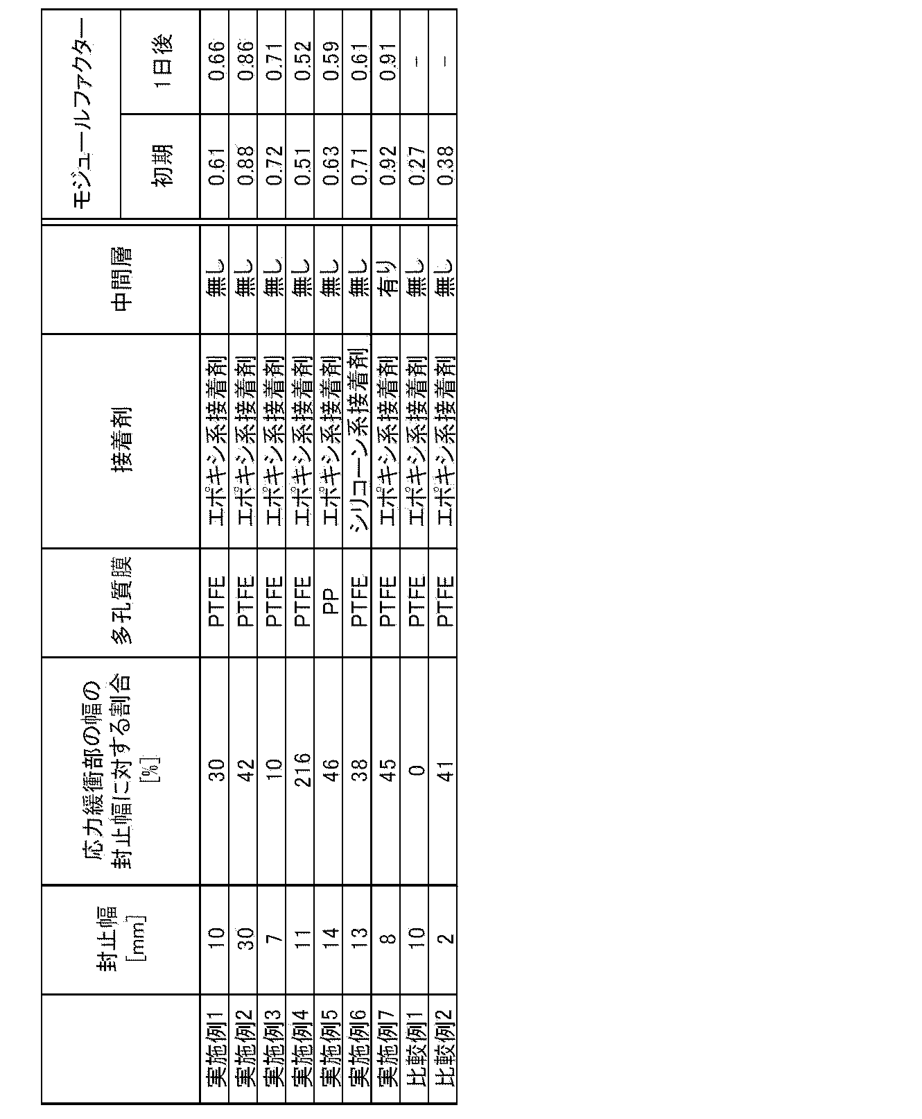
表2に示すように、本発明の酸性ガス分離用積層体を備えたスパイラルモジュールは、初期、1日後ともにモジュールファクターとして、0.5以上が確認できた。さらに、応力緩衝部の幅の封止幅に対する割合が50%以下である実施例1~3および5~7においては、0.6以上とより好ましいモジュールファクターを得ることができた。これは応力緩衝部の幅を抑制することにより、有効面積をより大きく確保することができるためと考えられる。また実施例7に示すように中間層を有することで、ガス透過性を保ちながらも積層体の応力緩衝能力を底上げすることができ、初期性能から高いモジュールファクターを示すことができた。一方で、比較例1は応力緩衝部の幅の封止幅に対する割合が0%、すなわち応力緩衝部を持たないモジュールであり、容易に欠陥が発生し、1日後にはモジュールファクターを測る事ができなかった。比較例2は封止幅が小さく、十分に封止できず、また、1日後には初期に封止できていた部分が剥がれ、モジュールファクターの測定ができなかった。
また、実施例1のモジュールにおいては、高圧下(2.0MPa)での評価においても高いモジュールファクターを有した。
Claims (10)
- 多孔質膜と補助支持膜とが積層されてなる多孔質支持体と、該多孔質支持体の前記多孔質膜側に配された、原料ガス中の酸性ガスと反応するキャリアおよび該キャリアを担持する親水性化合物を含有する酸性ガス分離促進輸送膜とからなる複合体膜、および
前記多孔質支持体の前記補助支持膜に面して積層された、前記複合体膜を透過した酸性ガスが流れる透過ガス流路用部材を備えた酸性ガス分離用積層体であって、
該酸性ガス分離用積層体の周縁に5mm以上の幅で前記多孔質膜に接着剤が染み込み率60%以上で浸透し、かつ前記補助支持膜および前記ガス流路用部材に接着剤がそれぞれ染み込み率60%以上で浸透して形成された封止部と、
該封止部に隣接し、少なくとも前記多孔質膜における前記接着剤の染み込み率が60%未満であり、かつ、少なくとも前記ガス流路用部材に前記接着剤が浸透して形成された応力緩衝部を備えていることを特徴とする酸性ガス分離用積層体。 - 前記応力緩衝部の幅が前記封止部の前記幅の0.1%以上50%以下である請求項1記載の酸性ガス分離用積層体。
- 前記多孔質膜がフッ素系樹脂材料からなる請求項1または2記載の酸性ガス分離用積層体。
- 前記多孔質膜がポリテトラフルオロエチレンからなるものである請求項3記載の酸性ガス分離用積層体。
- 前記接着剤がエポキシ系樹脂からなるものである請求項1から4いずれか1項記載の酸性ガス分離用積層体。
- 前記多孔質膜と前記酸性ガス分離促進輸送膜との間に中間層を有する請求項1から5いずれか1項記載の酸性ガス分離用積層体。
- 前記中間層が、シリコーン樹脂層である請求項6記載の酸性ガス分離用積層体。
- 透過ガス集合管と、
請求項1から7いずれか1項記載の酸性ガス分離用積層体とを備え、
該酸性ガス分離用積層体の前記封止部が形成されていない端部の前記透過ガス流路用部材が、前記透過ガス集合管に接続されてなるものである酸性ガス分離用モジュール。 - スパイラル型モジュールである請求項8記載の酸性ガス分離用モジュール。
- 平膜型モジュールである請求項8記載の酸性ガス分離用モジュール。
Priority Applications (1)
| Application Number | Priority Date | Filing Date | Title |
|---|---|---|---|
| US15/006,918 US9457319B2 (en) | 2013-07-30 | 2016-01-26 | Acidic gas separation laminate and acidic gas separation module provided with laminate |
Applications Claiming Priority (4)
| Application Number | Priority Date | Filing Date | Title |
|---|---|---|---|
| JP2013-157549 | 2013-07-30 | ||
| JP2013157549 | 2013-07-30 | ||
| JP2014152716A JP5990225B2 (ja) | 2013-07-30 | 2014-07-28 | 酸性ガス分離用積層体および該積層体を備えた酸性ガス分離用モジュール |
| JP2014-152716 | 2014-07-28 |
Related Child Applications (1)
| Application Number | Title | Priority Date | Filing Date |
|---|---|---|---|
| US15/006,918 Continuation US9457319B2 (en) | 2013-07-30 | 2016-01-26 | Acidic gas separation laminate and acidic gas separation module provided with laminate |
Publications (1)
| Publication Number | Publication Date |
|---|---|
| WO2015015803A1 true WO2015015803A1 (ja) | 2015-02-05 |
Family
ID=52431359
Family Applications (1)
| Application Number | Title | Priority Date | Filing Date |
|---|---|---|---|
| PCT/JP2014/003992 Ceased WO2015015803A1 (ja) | 2013-07-30 | 2014-07-30 | 酸性ガス分離用積層体および該積層体を備えた酸性ガス分離用モジュール |
Country Status (4)
| Country | Link |
|---|---|
| US (1) | US9457319B2 (ja) |
| JP (1) | JP5990225B2 (ja) |
| TW (1) | TW201511958A (ja) |
| WO (1) | WO2015015803A1 (ja) |
Cited By (2)
| Publication number | Priority date | Publication date | Assignee | Title |
|---|---|---|---|---|
| JPWO2018221236A1 (ja) * | 2017-06-01 | 2019-06-27 | Dic株式会社 | 重合性モノマー、それを用いた液晶組成物及び液晶表示素子 |
| EP4023326A4 (en) * | 2019-08-30 | 2023-09-13 | Toray Industries, Inc. | GAS SEPARATION MEMBRANE MODULE |
Families Citing this family (5)
| Publication number | Priority date | Publication date | Assignee | Title |
|---|---|---|---|---|
| EP3305395B1 (en) | 2015-05-29 | 2020-01-08 | Sumitomo Chemical Company, Limited | Spiral-wound acid gas separation membrane element, acid gas separation membrane module, and acid gas separation apparatus |
| KR101966115B1 (ko) * | 2017-11-14 | 2019-04-05 | (주)피엔티 | 역삼투 필터 모듈 제조 장치 |
| KR101966114B1 (ko) * | 2017-11-14 | 2019-08-13 | (주)피엔티 | 역삼투 필터 모듈 제조 장치 |
| KR101966118B1 (ko) * | 2017-11-14 | 2019-04-05 | (주)피엔티 | 역삼투 필터 모듈 제조 방법 |
| JP2020108881A (ja) * | 2018-12-28 | 2020-07-16 | 日東電工株式会社 | フィルタ濾材、フィルタプリーツパック、フィルタユニット |
Citations (5)
| Publication number | Priority date | Publication date | Assignee | Title |
|---|---|---|---|---|
| WO2013018659A1 (ja) * | 2011-08-01 | 2013-02-07 | 株式会社ルネッサンス・エナジー・リサーチ | Co2促進輸送膜及びその製造方法 |
| WO2013018538A1 (ja) * | 2011-07-29 | 2013-02-07 | 富士フイルム株式会社 | 二酸化炭素分離部材、その製造方法及び二酸化炭素分離モジュール |
| WO2013077418A1 (ja) * | 2011-11-25 | 2013-05-30 | 富士フイルム株式会社 | ガス分離膜、その製造方法、それを用いたガス分離膜モジュール |
| WO2013191147A1 (ja) * | 2012-06-20 | 2013-12-27 | 富士フイルム株式会社 | 酸性ガス分離モジュール及びその製造方法、酸性ガス分離層、その製造方法及びその促進輸送膜、並びに、酸性ガス分離システム |
| WO2014129098A1 (ja) * | 2013-02-22 | 2014-08-28 | 富士フイルム株式会社 | 酸性ガス分離用複合体、酸性ガス分離用モジュールおよび酸性ガス分離用モジュールの製造方法 |
Family Cites Families (20)
| Publication number | Priority date | Publication date | Assignee | Title |
|---|---|---|---|---|
| US2266367A (en) * | 1939-04-08 | 1941-12-16 | Hesser Edwin Bower | Positive printing in color photography |
| GB1241973A (en) * | 1968-07-30 | 1971-08-11 | American Standard Inc | Improvements in or relating to supporting osmotic membranes |
| JPH0368428A (ja) | 1989-08-07 | 1991-03-25 | Toray Ind Inc | 流体分離モジュール及びその製造方法 |
| EP0443642A3 (en) * | 1990-01-24 | 1991-09-11 | Shell Internationale Research Maatschappij B.V. | Process for the fabrication of a spirally wound membrane module |
| JPH05131123A (ja) * | 1991-11-08 | 1993-05-28 | Nitto Denko Corp | スパイラル型膜分離装置 |
| WO1993013849A1 (fr) * | 1992-01-14 | 1993-07-22 | Daikin Industries, Ltd. | Filtre et element filtrant |
| US5294342A (en) * | 1992-10-01 | 1994-03-15 | Hoechst Celanese Corporation | Composite porous membranes |
| NO304220B1 (no) * | 1996-04-30 | 1998-11-16 | Sintef | FremgangsmÕte til fremstilling av tynne metallmembraner |
| JP3578198B2 (ja) | 1998-01-30 | 2004-10-20 | 株式会社ユアサコーポレーション | 平板型膜モジユール |
| JPH11226366A (ja) | 1998-02-19 | 1999-08-24 | Toray Ind Inc | 流体分離膜エレメントの製造方法および装置ならびに流体分離膜エレメント |
| US6630093B1 (en) * | 1999-08-21 | 2003-10-07 | Ronald D. Jones | Method for making freeform-fabricated core composite articles |
| US6998193B2 (en) * | 2001-12-28 | 2006-02-14 | Policell Technologies, Inc. | Microporous membrane and its uses thereof |
| JP2005103516A (ja) * | 2003-10-02 | 2005-04-21 | Nitto Denko Corp | スパイラル型膜エレメント及びその製造方法 |
| TWI232888B (en) * | 2003-11-25 | 2005-05-21 | Min-Hung Lei | Method for producing supported palladium membrane for purification of high purity hydrogen |
| JP2009018239A (ja) | 2007-07-11 | 2009-01-29 | Toray Ind Inc | スパイラル型液体分離素子の製造方法 |
| EP2425889B1 (en) * | 2009-04-30 | 2014-09-03 | Asahi Kasei Fibers Corporation | Composite membrane substrate and composite membrane using same |
| CN103108690B (zh) * | 2010-07-26 | 2017-02-15 | 株式会社新生能源研究 | 水蒸汽选择透过膜及使用该透过膜从混合气体中分离水蒸汽的方法 |
| US20140231332A1 (en) * | 2011-09-29 | 2014-08-21 | Toray Industries, Inc. | Separation membrane and separation membrane element |
| JP5922836B2 (ja) * | 2012-03-13 | 2016-05-24 | ダブリュ.エル.ゴア アンド アソシエイツ,インコーポレイティドW.L. Gore & Associates, Incorporated | 通気アレイとその製造方法 |
| JP5829227B2 (ja) * | 2012-09-28 | 2015-12-09 | 富士フイルム株式会社 | 酸性ガス分離モジュール、酸性ガス分離装置、及びテレスコープ防止板 |
-
2014
- 2014-07-28 JP JP2014152716A patent/JP5990225B2/ja not_active Expired - Fee Related
- 2014-07-30 WO PCT/JP2014/003992 patent/WO2015015803A1/ja not_active Ceased
- 2014-07-30 TW TW103126093A patent/TW201511958A/zh unknown
-
2016
- 2016-01-26 US US15/006,918 patent/US9457319B2/en not_active Expired - Fee Related
Patent Citations (5)
| Publication number | Priority date | Publication date | Assignee | Title |
|---|---|---|---|---|
| WO2013018538A1 (ja) * | 2011-07-29 | 2013-02-07 | 富士フイルム株式会社 | 二酸化炭素分離部材、その製造方法及び二酸化炭素分離モジュール |
| WO2013018659A1 (ja) * | 2011-08-01 | 2013-02-07 | 株式会社ルネッサンス・エナジー・リサーチ | Co2促進輸送膜及びその製造方法 |
| WO2013077418A1 (ja) * | 2011-11-25 | 2013-05-30 | 富士フイルム株式会社 | ガス分離膜、その製造方法、それを用いたガス分離膜モジュール |
| WO2013191147A1 (ja) * | 2012-06-20 | 2013-12-27 | 富士フイルム株式会社 | 酸性ガス分離モジュール及びその製造方法、酸性ガス分離層、その製造方法及びその促進輸送膜、並びに、酸性ガス分離システム |
| WO2014129098A1 (ja) * | 2013-02-22 | 2014-08-28 | 富士フイルム株式会社 | 酸性ガス分離用複合体、酸性ガス分離用モジュールおよび酸性ガス分離用モジュールの製造方法 |
Cited By (4)
| Publication number | Priority date | Publication date | Assignee | Title |
|---|---|---|---|---|
| JPWO2018221236A1 (ja) * | 2017-06-01 | 2019-06-27 | Dic株式会社 | 重合性モノマー、それを用いた液晶組成物及び液晶表示素子 |
| JP2019194331A (ja) * | 2017-06-01 | 2019-11-07 | Dic株式会社 | 重合性モノマー、それを用いた液晶組成物及び液晶表示素子 |
| JP7006659B2 (ja) | 2017-06-01 | 2022-01-24 | Dic株式会社 | 重合性モノマー、それを用いた液晶組成物及び液晶表示素子 |
| EP4023326A4 (en) * | 2019-08-30 | 2023-09-13 | Toray Industries, Inc. | GAS SEPARATION MEMBRANE MODULE |
Also Published As
| Publication number | Publication date |
|---|---|
| US9457319B2 (en) | 2016-10-04 |
| JP5990225B2 (ja) | 2016-09-07 |
| JP2015044189A (ja) | 2015-03-12 |
| TW201511958A (zh) | 2015-04-01 |
| US20160136580A1 (en) | 2016-05-19 |
Similar Documents
| Publication | Publication Date | Title |
|---|---|---|
| JP5990556B2 (ja) | 酸性ガス分離用積層体および該積層体を備えた酸性ガス分離用モジュール | |
| JP5990225B2 (ja) | 酸性ガス分離用積層体および該積層体を備えた酸性ガス分離用モジュール | |
| JP6071004B2 (ja) | 酸性ガス分離複合膜の製造方法及び酸性ガス分離膜モジュール | |
| CN105473213B (zh) | 酸性气体分离模块 | |
| EP2959957A1 (en) | Complex for acid gas separation, module for acid gas separation, and method for manufacturing module for acid gas separation | |
| JP6001013B2 (ja) | 酸性ガス分離用スパイラル型モジュール | |
| WO2014156192A1 (ja) | 酸性ガス分離複合膜の製造方法及び酸性ガス分離膜モジュール | |
| JP6276598B2 (ja) | 酸性ガス分離用モジュール | |
| WO2015025812A1 (ja) | 酸性ガス分離用スパイラル型モジュール | |
| JP5999844B2 (ja) | 酸性ガス分離用モジュール | |
| JP6037965B2 (ja) | 酸性ガス分離モジュール | |
| WO2015107820A1 (ja) | 酸性ガス分離用スパイラル型モジュールおよび製造方法 | |
| JPWO2016117349A1 (ja) | 酸性ガス分離モジュール | |
| JP5972232B2 (ja) | 酸性ガス分離モジュール | |
| JP2015020147A (ja) | 酸性ガス分離用スパイラル型モジュール | |
| JP6392412B2 (ja) | 酸性ガス分離複合膜の製造方法及び酸性ガス分離用モジュール | |
| JP6005003B2 (ja) | 酸性ガス分離用スパイラル型モジュール | |
| JP2016064384A (ja) | 酸性ガス分離モジュール |
Legal Events
| Date | Code | Title | Description |
|---|---|---|---|
| 121 | Ep: the epo has been informed by wipo that ep was designated in this application |
Ref document number: 14832207 Country of ref document: EP Kind code of ref document: A1 |
|
| NENP | Non-entry into the national phase |
Ref country code: DE |
|
| 122 | Ep: pct application non-entry in european phase |
Ref document number: 14832207 Country of ref document: EP Kind code of ref document: A1 |