WO2015012044A1 - 治療用マニピュレータおよびマニピュレータシステム - Google Patents
治療用マニピュレータおよびマニピュレータシステム Download PDFInfo
- Publication number
- WO2015012044A1 WO2015012044A1 PCT/JP2014/066634 JP2014066634W WO2015012044A1 WO 2015012044 A1 WO2015012044 A1 WO 2015012044A1 JP 2014066634 W JP2014066634 W JP 2014066634W WO 2015012044 A1 WO2015012044 A1 WO 2015012044A1
- Authority
- WO
- WIPO (PCT)
- Prior art keywords
- joint
- main body
- arm
- manipulator
- bending
- Prior art date
Links
Images


Classifications
-
- A—HUMAN NECESSITIES
- A61—MEDICAL OR VETERINARY SCIENCE; HYGIENE
- A61B—DIAGNOSIS; SURGERY; IDENTIFICATION
- A61B34/00—Computer-aided surgery; Manipulators or robots specially adapted for use in surgery
- A61B34/30—Surgical robots
-
- A—HUMAN NECESSITIES
- A61—MEDICAL OR VETERINARY SCIENCE; HYGIENE
- A61B—DIAGNOSIS; SURGERY; IDENTIFICATION
- A61B34/00—Computer-aided surgery; Manipulators or robots specially adapted for use in surgery
- A61B34/30—Surgical robots
- A61B34/37—Master-slave robots
-
- A—HUMAN NECESSITIES
- A61—MEDICAL OR VETERINARY SCIENCE; HYGIENE
- A61B—DIAGNOSIS; SURGERY; IDENTIFICATION
- A61B1/00—Instruments for performing medical examinations of the interior of cavities or tubes of the body by visual or photographical inspection, e.g. endoscopes; Illuminating arrangements therefor
- A61B1/00064—Constructional details of the endoscope body
- A61B1/00071—Insertion part of the endoscope body
- A61B1/0008—Insertion part of the endoscope body characterised by distal tip features
- A61B1/00087—Tools
-
- A—HUMAN NECESSITIES
- A61—MEDICAL OR VETERINARY SCIENCE; HYGIENE
- A61B—DIAGNOSIS; SURGERY; IDENTIFICATION
- A61B1/00—Instruments for performing medical examinations of the interior of cavities or tubes of the body by visual or photographical inspection, e.g. endoscopes; Illuminating arrangements therefor
- A61B1/00147—Holding or positioning arrangements
- A61B1/00149—Holding or positioning arrangements using articulated arms
-
- A—HUMAN NECESSITIES
- A61—MEDICAL OR VETERINARY SCIENCE; HYGIENE
- A61B—DIAGNOSIS; SURGERY; IDENTIFICATION
- A61B34/00—Computer-aided surgery; Manipulators or robots specially adapted for use in surgery
- A61B34/70—Manipulators specially adapted for use in surgery
-
- A—HUMAN NECESSITIES
- A61—MEDICAL OR VETERINARY SCIENCE; HYGIENE
- A61B—DIAGNOSIS; SURGERY; IDENTIFICATION
- A61B17/00—Surgical instruments, devices or methods, e.g. tourniquets
- A61B17/28—Surgical forceps
- A61B17/29—Forceps for use in minimally invasive surgery
- A61B2017/2901—Details of shaft
- A61B2017/2906—Multiple forceps
-
- A—HUMAN NECESSITIES
- A61—MEDICAL OR VETERINARY SCIENCE; HYGIENE
- A61B—DIAGNOSIS; SURGERY; IDENTIFICATION
- A61B17/00—Surgical instruments, devices or methods, e.g. tourniquets
- A61B17/28—Surgical forceps
- A61B17/29—Forceps for use in minimally invasive surgery
- A61B2017/2926—Details of heads or jaws
- A61B2017/2927—Details of heads or jaws the angular position of the head being adjustable with respect to the shaft
-
- A—HUMAN NECESSITIES
- A61—MEDICAL OR VETERINARY SCIENCE; HYGIENE
- A61B—DIAGNOSIS; SURGERY; IDENTIFICATION
- A61B34/00—Computer-aided surgery; Manipulators or robots specially adapted for use in surgery
- A61B34/30—Surgical robots
- A61B2034/301—Surgical robots for introducing or steering flexible instruments inserted into the body, e.g. catheters or endoscopes
-
- A—HUMAN NECESSITIES
- A61—MEDICAL OR VETERINARY SCIENCE; HYGIENE
- A61B—DIAGNOSIS; SURGERY; IDENTIFICATION
- A61B34/00—Computer-aided surgery; Manipulators or robots specially adapted for use in surgery
- A61B34/30—Surgical robots
- A61B2034/305—Details of wrist mechanisms at distal ends of robotic arms
- A61B2034/306—Wrists with multiple vertebrae
-
- A—HUMAN NECESSITIES
- A61—MEDICAL OR VETERINARY SCIENCE; HYGIENE
- A61B—DIAGNOSIS; SURGERY; IDENTIFICATION
- A61B90/00—Instruments, implements or accessories specially adapted for surgery or diagnosis and not covered by any of the groups A61B1/00 - A61B50/00, e.g. for luxation treatment or for protecting wound edges
- A61B90/36—Image-producing devices or illumination devices not otherwise provided for
- A61B90/37—Surgical systems with images on a monitor during operation
- A61B2090/373—Surgical systems with images on a monitor during operation using light, e.g. by using optical scanners
Definitions
- the present invention relates to a therapeutic manipulator and a manipulator system.
- a therapeutic manipulator having two arms provided with two curved portions adjacent to the distal end of the insertion portion in the longitudinal direction is known (for example, see Patent Document 1).
- a treatment manipulator having an arm having two bending joints adjacent to each other in the longitudinal direction and a roll joint arranged on the base end side thereof is known in order to perform treatment on the side of the insertion portion ( For example, see Patent Document 2.)
- the joint on the distal end side that changes the direction of the treatment tool is curved with a gentle curve, so that it is possible to treat the affected part disposed in the vicinity of the insertion portion main body. There is an inconvenience that it cannot be done.
- the root roll joint in order to move the distal treatment tool in a direction intersecting the movement direction by the bending joint, the root roll joint must be operated, and almost the entire treatment manipulator is operated. Has a disadvantage in that it moves and comes into contact with surrounding tissues.
- the present invention has been made in view of the above-described circumstances, and is a therapeutic manipulator and a manipulator capable of treating an affected part disposed at a position close to the insertion portion main body while reducing interference with surrounding tissues and the like.
- the purpose is to provide a system.
- the present invention provides the following means.
- One aspect of the present invention is provided in the insertion portion main body, at least one arm provided to protrude forward from the distal end surface of the insertion portion main body, and having an end effector at the distal end, and the insertion portion main body.
- An endoscope having a field-of-view range in which the end effector at the distal end of the arm can be observed, and the arm is arranged in order from the distal end side around the first axis perpendicular to the longitudinal axis of the arm.
- a therapeutic manipulator in which a first bending joint can be bent at least 90 ° to at least one side with respect to the longitudinal axis.
- the arm when the insertion portion main body is inserted into the body cavity from the distal end surface side, the arm is disposed so as to protrude forward from the distal end surface, and treatment with the arm can be performed on the inner body wall in front of the insertion portion.
- the first bendable joint that is bendable at 90 ° or more arranged on the distal end side allows easy access to a portion disposed at a position close to the distal end surface of the apparatus main body and performs treatment by the end effector at the distal end. Can be applied.
- the end effector treating the part close to the apparatus main body in a state where the first bending joint is bent in the body cavity is moved in a direction intersecting the bending plane by the first bending joint.
- Rotate the intermediate roll joint When the intermediate roll joint arranged between the first flex joint and the second flex joint is rotated, only the first flex joint and the end effector arranged on the tip side of the intermediate roll joint are rotated. It is possible to reduce the radius of rotation and reduce the interference between the surrounding tissue and the arm.
- the insertion portion main body is provided with a through hole that penetrates along the longitudinal direction of the insertion portion main body and opens at the distal end surface, and movably accommodates the endoscope. Further, a notch having a width dimension larger than the outer diameter dimension of the endoscope may be provided over a predetermined length range from the opening of the distal end surface.
- the insertion portion main body is inserted into the body cavity while the endoscope is accommodated in the through hole provided in the insertion portion main body, and is accommodated in the through hole in the vicinity of the treatment site.
- the endoscope By moving the formed endoscope in the longitudinal direction of the through-hole, the endoscope can be advanced and retracted in the longitudinal direction and protruded from the opening on the distal end surface of the insertion portion main body.
- the protruded endoscope can bend the bending portion provided in the endoscope so as to direct the field of view in a desired direction, and observe the end effector arranged at the tip of the arm.
- the endoscope protruded from the opening of the distal end surface of the insertion portion main body is curved and is retracted in the longitudinal direction of the through hole
- the intermediate position in the length direction of the endoscope is By being accommodated in the notch provided at the tip of the through hole, the endoscope in the through hole can be protruded outward in the radial direction of the insertion portion main body through the notch. Therefore, the endoscope can be advanced and retracted while the bending portion is curved, and the visual field range can be advanced and retracted, and the same observation site can be observed while changing the angle.
- the drive wire which drives the said end effector may be arrange
- the first bending joint can be bent at 90 ° or more only on one side with respect to the longitudinal axis, and there is a passage through which the driving wire rod passes through the first bending joint.
- a swinging member provided so as to be passively swingable around the bending center of the first bending joint may be provided in accordance with the operation of the curved driving wire.
- the slack of the driving wire disposed in the passage in the first bending joint can be minimized, and the swinging member can be swung passively following the movement of the driving wire. By doing so, it is not necessary to apply an excessive load to the drive wire. Accordingly, even if the first bending joint is swung between a state in which the first bending joint is extended in the direction along the longitudinal axis and a state in which the first bending joint is bent by 90 ° or more on one side, the driving wire rod is loosened in the radial direction of the arm. It is possible to prevent the kink from protruding outward or being subjected to an excessive load.
- a tubular guide member is radial direction through the said opening part.
- a guide groove that can be inserted from the outside may be provided.
- a slave device including any one of the above-described treatment manipulators, a drive unit that drives the treatment manipulator, a master device including an operation unit operated by an operator,
- a manipulator system comprising: a controller that controls a drive unit of the slave device based on an input signal input by the operation unit of a master device.
- the controller when the controller generates an operation command signal for each joint of the slave device based on an input signal from the master device, the first bending joint is moved from the center of the endoscopic image. You may calculate the operation command signal of each said joint so that it may arrange
- FIG. 1 It is a whole lineblock diagram showing a manipulator system provided with a manipulator for treatment concerning one embodiment of the present invention. It is a perspective view which shows the manipulator for a treatment which concerns on one Embodiment of this invention with which the manipulator system of FIG. 1 is equipped. It is a perspective view which shows the arm with which the treatment manipulator of FIG. 2 was equipped. It is a schematic diagram which shows the axial structure of the arm of FIG. It is a schematic diagram which shows the internal structure of the state extended in the linear form of the arm of FIG.
- FIG. 4 is a schematic diagram showing an internal structure in a state where a first bending joint of the arm of FIG. 3 is bent.
- a manipulator system 1 includes a treatment manipulator 2 according to this embodiment that is inserted into a body cavity of a patient P and a slave device 3 that includes a drive unit (not shown). Obtained by the master device 4 having an operation unit operated by the operator A, the controller 5 that controls the drive unit of the slave device 3 based on an input signal by the operation of the master device 4, and the treatment manipulator 2. And a monitor 6 for displaying an image.
- the treatment manipulator 2 includes a flexible tubular insertion portion main body 7 and two arms 8 provided to project forward from the distal end surface of the insertion portion main body 7. And an endoscope 9 movably accommodated in a through hole 7a (see FIG. 7) provided along the longitudinal direction of the insertion portion main body 7.
- the broken line is an enlarged view of the distal end portion of the insertion portion main body 7, and reference numeral 10 is introduced through a forceps channel 7 b (see FIG. 7) provided along the longitudinal direction of the insertion portion main body 7.
- the treatment tool arranged in a protruding manner is shown.
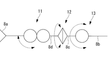
- the two arms 8 are bent around the end effector 8a such as a grasping forceps and the axis A2 orthogonal to the longitudinal axis A1 in order from the distal end side along the longitudinal axis direction.
- a possible first bending joint 11, an intermediate roll joint 12 that can rotate about the longitudinal axis A 1, and a second bending joint 13 that can be bent about an axis A 3 orthogonal to the longitudinal axis A 1 are provided.
- the arm 8 is described as being fixed to the insertion portion main body 7.
- the arm 8 may protrude from a channel (not shown) of the insertion portion main body 7. The case of protruding from the channel operates in the same manner as the case of being fixed to the insertion portion main body 7.
- the second bending joint 13 has a columnar first arm portion 8c around an axis A3 orthogonal to the longitudinal axis of the fixing portion 8b with respect to the columnar fixing portion 8b fixed to the insertion portion main body 7.
- the fixed portion 8b is supported so as to be swingable over an angle range of ⁇ 90 ° with respect to the longitudinal axis of the fixed portion 8b.
- the intermediate roll joint 12 supports a columnar second arm portion 8d arranged coaxially with the first arm portion 8c so as to be rotatable by ⁇ 180 ° around the longitudinal axis A1 with respect to the first arm portion 8c. is doing.
- the first bending joint 11 connects the second arm portion 8d and the end effector 8a by a link member 8e, the link member 8e with respect to the second arm portion 8d, and the end effector 8a with respect to the link member 8e.
- the double joint type joint includes, for example, gears (not shown) that mesh with each other in the second arm portion 8d and the end effector 8a, and when the link member 8e is swung around the axis A2, This is a joint that is also swung with respect to the link member 8e when the end effector 8a is rotated about the axis A4.
- the end effector 8a can be swung at an angle larger than the swiveling angle around the axis A2, and a wide operating angle range can be realized. Yes. Thereby, the first bending joint 11 can bend the end effector 8a only over one side with respect to the longitudinal axis A1 of the second arm portion 8d over an angular range of 170 °.
- the first bending joint 11 is not limited to the double joint type described above. Specifically, even if it is a joint that can be rotated around one rotation axis without using the link member 8e. Good.
- the first bending joint 11 is provided with disk-like swinging members 14 and 15 that are supported so as to be swingable about two axes A2 and A4, respectively. Yes.
- the swing members 14 and 15 are provided with passages 14a and 15a penetrating the inside in the radial direction.
- the passages 14a and 15a have heights in the directions of the axes A2 and A4 that can accommodate the sheath 16b through which the drive wire 16a for driving the end effector 8a is inserted, and an axis A2 that is formed to be sufficiently wider than the sheath 16b. , And a width dimension in a direction orthogonal to A4.
- the drive wire 16a is not limited, and an elongated flexible rod may be used.
- reference numeral 17a is a wire for driving the first bending joint 11
- reference numeral 17b is a sheath for inserting the wire 17a
- reference numeral 18a is a wire for driving the intermediate roll joint 12
- reference numeral 18b is A sheath through which the wire 18a is inserted
- reference numeral 19a is a wire for driving the second bending joint 13
- reference numeral 19b is a sheath through which the wire 19a is inserted.
- the endoscope 9 includes an observation optical system (not shown) having a visual field range in front of the distal end surface, and has two curved portions 9a and 9b adjacent to each other with a gap in the longitudinal direction. As shown in FIG. 2, it is possible to take a linear form in which the curved parts 9a and 9b shown in FIG. 2 are extended, or an S-shaped form in which the two curved parts 9a and 9b are curved in opposite directions. ing. By taking a linear form, it can be accommodated in the through hole 7a of the insertion portion main body 7, so that smooth insertion into the body cavity can be performed. On the other hand, the visual field range can be directed to a position close to the distal end surface of the insertion portion main body 7 by taking the S-shaped form.
- the affected part or the inner surface of the body cavity in the direction opposite to the insertion direction of the insertion part main body 7 A field of view can be secured for B and treatment can be performed.
- the distal end of the insertion portion main body 7 is provided with a notch 7b formed by notching the through hole 7a radially outward from the distal end surface over a predetermined length in the longitudinal direction.
- the through hole 7a is provided at a position eccentric with respect to the central axis of the insertion portion main body 7, and the notch 7b is formed toward the side opposite to the central axis of the insertion portion main body 7 with the through hole 7a interposed therebetween.
- the width dimension of the notch 7 b is formed larger than the outer diameter dimension of the endoscope 9.
- the endoscope 9 can be accommodated in the through-hole 7a as shown in FIG. 7 as shown in FIG. Even when the curved portions 9a and 9b are curved, they can be projected outwardly in the radial direction of the insertion portion main body 7 through the notches 7b as long as they are curved toward the notches 7b. .
- the bending portions 9a and 9b of the endoscope 9 are fixed in a S-curved shape, and the endoscope 9 is advanced and retracted in the longitudinal direction of the through hole 7a, as shown in FIG.
- the field of view disposed in the vicinity of the distal end surface of the insertion portion main body 7 can be translated in the longitudinal direction of the insertion portion main body 7.
- the viewpoint of the same part can be changed by changing the bending angle of the two bending portions 9a and 9b while moving the endoscope 9 in the longitudinal direction of the through hole 7a. Can be done.
- the first bending joint 11, the intermediate roll joint 12, and the second bending joint 13 are driven by wires 17a, 18a, and 19a as shown in FIGS.
- Each wire 17a, 18a, 19a extends to the proximal end side of the insertion portion body 7 through the insertion portion body 7.
- the wires 17 a, 18 a, and 19 a are connected to the drive unit disposed in the controller 5 via the relay unit 20 attached to the proximal end side of the insertion unit main body 7, and in the longitudinal direction of the insertion unit main body 7. It is designed to be pushed and pulled.
- a treatment instrument port 21 is provided in the relay section 20, and the treatment instrument 10 protruding from the distal end surface of the insertion section main body 7 passes through the treatment instrument port 21 and is inserted into the insertion section.
- the body 7 is inserted into the forceps channel 7b.
- the endoscope 9 includes an operation unit (not shown) at a proximal end portion that protrudes from the proximal end side of the insertion portion main body 7, and the bending portions 9a and 9b can be bent in an arbitrary direction by operation of the operation portion. It can be done.
- the two arms projecting from the distal end surface of the insertion portion main body 7 of the treatment manipulator 2.
- 8 flexion joint 11 is bent to about 180 °
- intermediate roll joint 12 is rolled at an angle such that arm 8 is housed inside the outer diameter of insertion portion body 7, and second flexure joint 13 is straightened.
- the endoscope 9 is inserted into the body cavity of the patient P, for example, the anus.
- the operator A operates the master device 4 to operate the two arms 8 and operates the operation section of the endoscope 9.
- a visual field is arranged at a position where the affected part and the end effector 8a at the tip of the arm 8 can be observed.
- the video imaged by the endoscope 9 is displayed on the monitor 6, and the operator A operates the master device 4 and the operation unit of the endoscope 9 while checking the monitor 6.
- each of the two arms 8 has two bending joints 11 and 13 spaced apart in the longitudinal direction, the two bending joints 11 and 13 are bent in opposite directions, as shown in FIG.
- the end effector 8a can be advanced and retracted in the shape of a simple SCARA arm.
- the first bending joint has a swing angle range of 170 ° on one side, the end effector is bent so as to be completely folded with respect to the arm, and the end of the end effector is connected to the insertion portion main body. It can be made close to the vicinity of the tip surface.
- the first bending joint 11 and the second bending joint 13 of the two arms 8 are bent in opposite directions, respectively.
- the end effector 8a can be disposed within the visual field range R, and the arm 8 can be disposed outside the visual field range R, so that the arm 8 does not interfere with the visual field.
- the distal end of the end effector 8a arranged in the vicinity of the distal end surface of the insertion portion main body 7 in this way rotates the intermediate roll joint 12, thereby causing the operation plane of the end effector 8a by the first bending joint 11 (FIG. 11). Can be moved in a direction that intersects the plane of FIG. 11 (a direction that intersects the plane of FIG. 11).
- the intermediate roll joint 12 is disposed between the first bending joint 11 and the second bending joint 13, a conventional case having a roll joint disposed on the proximal side from the second bending joint 13.
- the arm 8 portion that is operated by the rotation of the intermediate roll joint 12 can be shortened, and the radius of rotation can be reduced to reduce interference with surrounding tissues.
- the wire 16a for driving the end effector 8a is inserted into the passages 14a and 15a in the swing members 14 and 15 disposed so as to be swingable around the two axes A2 and A4 of the first bending joint 11. Since the sheath 16b is inserted into the sheath 16b, the slackness of the sheath 16b in the passages 14a and 15a changes between the state where the first bending joint 11 is bent by 170 ° and the state where the first bending joint 11 is straightened. Since the passages 14a and 15a inside the swing members 14 and 15 have a sufficiently wide width, the sheath 16b can be accommodated in any state.
- the notch 7b is provided from the distal end surface of the insertion portion main body 7 over a predetermined length, the affected portions are observed by curving the curved portions 9a and 9b.
- the field-of-view range R can be translated in parallel by moving the endoscope 9 in the longitudinal direction of the through-hole 7a with the endoscope 9 being curved. In particular, this is effective when observing the affected part arranged at a position close to the distal end surface of the insertion portion main body 7.
- the arm 8 having the two bending joints 11 and 13 and the intermediate roll joint 12 disposed therebetween is described as an example.
- a proximal-side roll joint 22 that rotates the link 8f about the axis A5 relative to the fixed portion 8b may be further provided on the proximal side of the joint 13.
- the bent first bent joint 11 can be rotated around the axis A5 of the fixed portion 8b.
- the first bending joint 11 and the second bending joint 13 of the two arms 8 are bent in the opposite directions so that the first bending joint 11 stretches both elbows.
- both elbows can be folded up in a compact manner as if they were raised.
- the treatment instrument 10 is introduced through the forceps channel 7b formed of a through hole provided in the insertion portion main body 7.
- a guide groove 23 having an opening 23 a that opens on the outer peripheral surface of the insertion portion main body 7 may be provided over the entire length of the insertion portion main body 7.
- the width dimension of the opening 23a of the guide groove 23 is a width dimension in which an observation endoscope (guide member) 24 (see FIG. 14) can be inserted.
- the endoscope 24 for observation is introduced into the body cavity, and the tip is placed near the affected area while observing the inside of the body cavity.
- a portion of the observation endoscope 24 arranged outside the body of the patient P is accommodated in the guide groove 23 from the opening 23a, thereby using the observation endoscope 24 as a guide and a therapeutic manipulator. 2 can be introduced more easily into the body cavity of the patient P.
- the distal end portion is exposed outside the body of the observation endoscope 24 disposed in the body cavity.
- the insertion portion main body 7 can be attached to a position in the middle of the longitudinal direction, and the treatment manipulator 2 can be inserted into the body cavity without removing the observation endoscope 24 from the body cavity. There is an advantage that you can.
- the guide groove 23 may be opened with the maximum width as shown in FIG. 14 (a), or the width of the opening 23a may be smaller than the maximum width as shown in FIG. 14 (b).
- the endoscope 24 for observation is accommodated in the guide groove 23 while expanding the opening 23a of the insertion portion body 7 made of a flexible material. Further, it is possible to prevent the therapeutic manipulator 2 from being detached from the endoscope 24.
- the bending angle of the first bending joint 11 is set to 170 ° on one side, but is not limited to this, and may be 90 ° or more on at least one side.
- the angle range of the second bending joint 13 is ⁇ 90 °, it is only necessary that the second bending joint 13 can be bent to an arbitrary angle range instead.
Landscapes
- Health & Medical Sciences (AREA)
- Life Sciences & Earth Sciences (AREA)
- Surgery (AREA)
- Engineering & Computer Science (AREA)
- General Health & Medical Sciences (AREA)
- Veterinary Medicine (AREA)
- Public Health (AREA)
- Animal Behavior & Ethology (AREA)
- Nuclear Medicine, Radiotherapy & Molecular Imaging (AREA)
- Molecular Biology (AREA)
- Biomedical Technology (AREA)
- Heart & Thoracic Surgery (AREA)
- Medical Informatics (AREA)
- Robotics (AREA)
- Biophysics (AREA)
- Radiology & Medical Imaging (AREA)
- Physics & Mathematics (AREA)
- Pathology (AREA)
- Optics & Photonics (AREA)
- Surgical Instruments (AREA)
- Endoscopes (AREA)
- Manipulator (AREA)
Abstract
周囲の組織等との干渉を低減しつつ挿入部本体に近接した位置に配置される患部を処置する。挿入部本体(7)と、挿入部本体(7)の先端面から前方に突出するように設けられ、先端にエンドエフェクタ(8a)を有する少なくとも1本のアーム(8)と、挿入部本体(7)に設けられ、アーム(8)先端のエンドエフェクタ(8a)を観察可能な視野範囲を有する内視鏡(9)とを備え、アーム(8)が、先端側から順に、アーム(8)の長手軸に直交する第1の軸線回りにエンドエフェクタ(8a)を揺動可能な第1の屈曲関節(11)と、長手軸回りに回転可能な中間ロール関節(12)と、長手軸に直交する第2の軸線回りに揺動可能な第2の屈曲関節(13)とを備え、第1の屈曲関節(11)が、長手軸に対して少なくとも片側に90°以上屈曲可能である治療用マニピュレータ(2)を提供する。
Description
本発明は、治療用マニピュレータおよびマニピュレータシステムに関するものである。
従来、挿入部の先端に長手方向に隣接して2つの湾曲部を備える2本のアームを有する治療用マニピュレータが知られている(例えば、特許文献1参照。)。また、挿入部の側方において処置を行うために、長手方向に隣接する2つの屈曲関節とその基端側に配置されたロール関節とを有するアームを備えた治療用マニピュレータが知られている(例えば、特許文献2参照。)。
しかしながら、特許文献1の治療用マニピュレータでは処置具の向きを変更する先端側の関節が緩いカーブを描いて湾曲するものであるために挿入部本体近傍に配置されている患部の処置を行うことができないという不都合がある。また、特許文献2の治療用マニピュレータでは先端の処置具を屈曲関節による移動方向に対して交差する方向に移動させるためには根元のロール関節を動作させなければならず、治療用マニピュレータのほぼ全体が移動することとなって、周囲の組織等と接触するという不都合がある。
本発明は上述した事情に鑑みてなされたものであって、周囲の組織等との干渉を低減しつつ挿入部本体に近接した位置に配置される患部を処置することができる治療用マニピュレータおよびマニピュレータシステムを提供することを目的としている。
上記目的を達成するために、本発明は以下の手段を提供する。
本発明の一態様は、挿入部本体と、該挿入部本体の先端面から前方に突出するように設けられ、先端にエンドエフェクタを有する少なくとも1本のアームと、前記挿入部本体に設けられ、前記アーム先端の前記エンドエフェクタを観察可能な視野範囲を有する内視鏡とを備え、前記アームが、前記先端側から順に、該アームの長手軸に直交する第1の軸線回りに前記エンドエフェクタを揺動可能な第1の屈曲関節と、前記長手軸回りに回転可能な中間ロール関節と、前記長手軸に直交する第2の軸線回りに揺動可能な第2の屈曲関節とを備え、前記第1の屈曲関節が、前記長手軸に対して少なくとも片側に90°以上屈曲可能である治療用マニピュレータを提供する。
本発明の一態様は、挿入部本体と、該挿入部本体の先端面から前方に突出するように設けられ、先端にエンドエフェクタを有する少なくとも1本のアームと、前記挿入部本体に設けられ、前記アーム先端の前記エンドエフェクタを観察可能な視野範囲を有する内視鏡とを備え、前記アームが、前記先端側から順に、該アームの長手軸に直交する第1の軸線回りに前記エンドエフェクタを揺動可能な第1の屈曲関節と、前記長手軸回りに回転可能な中間ロール関節と、前記長手軸に直交する第2の軸線回りに揺動可能な第2の屈曲関節とを備え、前記第1の屈曲関節が、前記長手軸に対して少なくとも片側に90°以上屈曲可能である治療用マニピュレータを提供する。
本態様によれば、体腔内に先端面側から挿入部本体を挿入すると、先端面から前方に突出するようにアームが配置され、挿入部の前方の体腔内壁に対しアームによる処置を行うことができる。この場合に、先端側に配置される90°以上屈曲可能な第1の屈曲関節によって、装置本体の先端面に近接する位置に配置される部位に容易にアクセスして先端のエンドエフェクタによって処置を施すことができる。
この場合において、体腔内において第1の屈曲関節を屈曲させた状態で装置本体に近接する部位を処置しているエンドエフェクタを第1の屈曲関節による屈曲平面に対して交差する方向に移動させるには、中間ロール関節を回転させる。第1の屈曲関節と第2の屈曲関節との間に配置された中間ロール関節を回転させると、中間ロール関節よりも先端側に配置されている第1の屈曲関節およびエンドエフェクタのみを回転させることができ、回転半径を小さくして周囲の組織とアームとの干渉を低減することができる。
上記態様においては、前記挿入部本体に、該挿入部本体の長手方向に沿って貫通して前記先端面に開口し、前記内視鏡を移動可能に収容する貫通孔が設けられ、該貫通孔に、前記先端面の開口から所定の長さ範囲にわたって前記内視鏡の外径寸法より大きな幅寸法を有する切欠が設けられていてもよい。
このようにすることで、挿入部本体に設けられた貫通孔内に内視鏡を収容した状態で挿入部本体を体腔内に挿入していき、処置する部位の近傍において、貫通孔内に収容された内視鏡を貫通孔の長手方向に移動させることにより、内視鏡を長手方向に進退させ、挿入部本体の先端面の開口から突出させることができる。突出させられた内視鏡は、該内視鏡に備えられた湾曲部を湾曲させて所望の方向に視界を向け、アームの先端に配置されているエンドエフェクタを観察することができる。
この場合において、挿入部本体の先端面の開口から突出させた内視鏡を湾曲させたままの形態で、貫通孔の長手方向に後退させると、内視鏡の長さ方向の途中位置が、貫通孔の先端に設けられた切欠に収容されることにより、切欠を介して貫通孔内の内視鏡を挿入部本体の半径方向外方に突出させることができる。したがって、湾曲部を湾曲させたままで内視鏡を進退させることができ、視野範囲を進退させたり、角度を変えながら同一の観察部位を観察したりすることができる。
また、上記態様においては、前記エンドエフェクタを駆動する駆動用線材が、前記アームを構成している各関節の内部を貫通して配置されていてもよい。
このようにすることで、駆動用線材がアームの外側に飛び出すことを防止しつつエンドエフェクタを駆動でき、駆動用線材によって視界が妨げられる不都合の発生を防止することができる。
このようにすることで、駆動用線材がアームの外側に飛び出すことを防止しつつエンドエフェクタを駆動でき、駆動用線材によって視界が妨げられる不都合の発生を防止することができる。
また、上記態様においては、前記第1の屈曲関節が、前記長手軸線に対して片側のみに90°以上屈曲可能であり、該第1の屈曲関節内に前記駆動用線材を貫通させる通路を有し、湾曲する前記駆動用線材の動作に応じて、前記第1の屈曲関節の屈曲中心回りに受動的に揺動可能に設けられた揺動部材を備えていてもよい。
このようにすることで、第1の屈曲関節内の通路に配置される駆動用線材の弛みを最小限に抑えることができ、駆動用線材の移動に倣って揺動部材を受動的に揺動させることで、駆動用線材に無理な負荷をかけずに済む。これにより、第1の屈曲関節を長手軸に沿う方向に延ばした状態と片側に90°以上屈曲させた状態との間で揺動させても、駆動用線材が、その弛みによってアームの半径方向外方に突出したり、無理な負荷がかかってキンクが生じたりすることを防止することができる。
また、上記態様においては、前記第2の屈曲関節よりも基端側に、前記長手軸回りに回転可能な基端側ロール関節を備えていてもよい。
このようにすることで、基端側ロール関節を回転させると、エンドエフェクタから第2の屈曲関節を含むアームのほぼ全体を回転させることができる。これにより、アームと体腔内壁との干渉を抑える範囲内において基端側ロール関節を回転させてアームを内視鏡の視界から退避させることができる。
このようにすることで、基端側ロール関節を回転させると、エンドエフェクタから第2の屈曲関節を含むアームのほぼ全体を回転させることができる。これにより、アームと体腔内壁との干渉を抑える範囲内において基端側ロール関節を回転させてアームを内視鏡の視界から退避させることができる。
また、上記態様においては、前記挿入部本体の外面に、長手方向に沿って設けられるとともに、径方向外方に開口する開口部を有し、管状のガイド部材を前記開口部を介して径方向外方から挿入可能な案内溝が設けられていてもよい。
このようにすることで、管状のガイド部材を体腔内に導入した状態で、ガイド部材の体外に配される部分が、開口部から案内溝内に収容されるように、挿入部本体をガイド部材に装着し、ガイド部材の長手方向に沿って挿入部本体を移動させることにより、容易に体腔内に挿入していくことができる。ガイド部材は、例えば、内視鏡である。
このようにすることで、管状のガイド部材を体腔内に導入した状態で、ガイド部材の体外に配される部分が、開口部から案内溝内に収容されるように、挿入部本体をガイド部材に装着し、ガイド部材の長手方向に沿って挿入部本体を移動させることにより、容易に体腔内に挿入していくことができる。ガイド部材は、例えば、内視鏡である。
また、本発明の他の態様は、上記いずれかの治療用マニピュレータと、該治療用マニピュレータを駆動する駆動部とを備えるスレーブ装置と、操作者により操作される操作部を備えるマスタ装置と、該マスタ装置の前記操作部により入力された入力信号に基づいて前記スレーブ装置の駆動部を制御するコントローラとを備えるマニピュレータシステムを提供する。
上記態様においては、前記コントローラが、前記マスタ装置からの入力信号に基づいて前記スレーブ装置の各前記関節の動作指令信号を生成する際に、前記第1の屈曲関節が内視鏡画像の中心からより離れた位置に配置されるように、各前記関節の動作指令信号を算出してもよい。
本発明によれば、周囲の組織等との干渉を低減しつつ挿入部本体に近接した位置に配置される患部を処置することができるという効果を奏する。
本発明の一実施形態に係る治療用マニピュレータおよびマニピュレータシステムについて、図面を参照して以下に説明する。
本実施形態に係るマニピュレータシステム1は、図1に示されるように、患者Pの体腔内に挿入される本実施形態に係る治療用マニピュレータ2およびその駆動部(図示略)を備えるスレーブ装置3と、操作者Aにより操作される操作部を備えるマスタ装置4と、該マスタ装置4の操作による入力信号に基づいてスレーブ装置3の駆動部を制御するコントローラ5と、治療用マニピュレータ2により取得された画像を表示するモニタ6とを備えている。
本実施形態に係るマニピュレータシステム1は、図1に示されるように、患者Pの体腔内に挿入される本実施形態に係る治療用マニピュレータ2およびその駆動部(図示略)を備えるスレーブ装置3と、操作者Aにより操作される操作部を備えるマスタ装置4と、該マスタ装置4の操作による入力信号に基づいてスレーブ装置3の駆動部を制御するコントローラ5と、治療用マニピュレータ2により取得された画像を表示するモニタ6とを備えている。
本実施形態に係る治療用マニピュレータ2は、図2に示されるように、軟性の管状の挿入部本体7と、該挿入部本体7の先端面から前方に突出して設けられた2本のアーム8と、挿入部本体7の長手方向に沿って設けられた貫通孔7a(図7参照)に移動可能に収容された内視鏡9とを備えている。図中、破線は挿入部本体7の先端部分の拡大図であり、符号10は挿入部本体7の長手方向に沿って設けられた鉗子チャネル7b(図7参照)を介して導入され先端面から突出して配置された処置具を示している。
2本のアーム8は、図3および図4に示されるように、先端側から長手軸方向に沿って順に、把持鉗子のようなエンドエフェクタ8aと、長手軸A1に直交する軸線A2回りに屈曲可能な第1の屈曲関節11と、長手軸A1回りに回転可能な中間ロール関節12と、長手軸A1に直交する軸線A3回りに屈曲可能な第2の屈曲関節13とを備えている。
本実施形態においては、アーム8が、挿入部本体7に固定されているものとして説明するが、挿入部本体7のチャネル(図示略)から突出していてもよい。チャネルから突出している場合も挿入部本体7に固定されている場合と同様に作動する。
本実施形態においては、アーム8が、挿入部本体7に固定されているものとして説明するが、挿入部本体7のチャネル(図示略)から突出していてもよい。チャネルから突出している場合も挿入部本体7に固定されている場合と同様に作動する。
第2の屈曲関節13は、挿入部本体7に固定された柱状の固定部8bに対して、該固定部8bの長手軸に直交する軸線A3回りに、柱状の第1のアーム部8cを、固定部8bの長手軸に対して±90°の角度範囲にわたって揺動可能に支持している。
中間ロール関節12は、第1のアーム部8cと同軸に配置される柱状の第2のアーム部8dを、第1のアーム部8cに対してその長手軸A1回りに±180°回転可能に支持している。
中間ロール関節12は、第1のアーム部8cと同軸に配置される柱状の第2のアーム部8dを、第1のアーム部8cに対してその長手軸A1回りに±180°回転可能に支持している。
第1の屈曲関節11は、第2のアーム部8dとエンドエフェクタ8aとをリンク部材8eによって連結し、第2のアーム部8dに対してリンク部材8eを、リンク部材8eに対してエンドエフェクタ8aをそれぞれ相互に平行な軸線A2,A4回りに揺動させるダブルジョイント型の関節である。ここで、ダブルジョイント型の関節は、第2のアーム部8dおよびエンドエフェクタ8aに、例えば、相互に噛み合う歯車(図示略)を備えており、軸線A2回りにリンク部材8eを揺動させると、エンドエフェクタ8aが軸線A4回りに回転させられることによりリンク部材8eに対しても揺動させられる関節である。
ダブルジョイント型の第1の屈曲関節11によれば、軸線A2回りの揺動角度より大きな角度でエンドエフェクタ8aを揺動させることができ、広い動作角度範囲を実現することができるようになっている。これにより、第1の屈曲関節11は、第2のアーム部8dの長手軸A1に対して片側のみにエンドエフェクタ8aを170°の角度範囲にわたって屈曲させることができるようになっている。
なお、第1の屈曲関節11においては、上述したダブルジョイント型に限られるものではなく、具体的にはリンク部材8eを用いず、1つの回動軸回りに回動可能な関節であってもよい。
なお、第1の屈曲関節11においては、上述したダブルジョイント型に限られるものではなく、具体的にはリンク部材8eを用いず、1つの回動軸回りに回動可能な関節であってもよい。
第1の屈曲関節11には、図5および図6に示されるように、2つの軸線A2,A4回りにそれぞれ揺動可能に支持された円板状の揺動部材14,15が設けられている。各揺動部材14,15には、内部を径方向に貫通する通路14a,15aが設けられている。通路14a,15aは、エンドエフェクタ8aを駆動するための駆動ワイヤ16aを挿通させるシース16bを収容可能な軸線A2,A4方向の高さ寸法と、シース16bよりも十分に幅広に形成された軸線A2,A4に直交する方向の幅寸法とを有している。なお、駆動ワイヤ16aに限定されるものではなく、細長い可撓性を有するロッドでもよい。
図5および図6において、符号17aは第1の屈曲関節11を駆動するためのワイヤ、符号17bはワイヤ17aを挿通させるシース、符号18aは中間ロール関節12を駆動する為のワイヤ、符号18bはワイヤ18aを挿通させるシース、符号19aは第2の屈曲関節13を駆動するためのワイヤ、符号19bはワイヤ19aを挿通させるシースである。
内視鏡9は、先端面にその前方に視野範囲を有する観察光学系(図示略)を備えるとともに、長手方向に間隔をあけて隣接する2つの湾曲部9a,9bを有し、図7に示される湾曲部9a,9bを延ばした直線状の形態や、図2に示されるように2つの湾曲部9a,9bを逆方向に湾曲させたS字状の形態をとることができるようになっている。直線状の形態をとることにより、挿入部本体7の貫通孔7a内に収容可能となるので、体腔へのスムーズな挿入を行うことができる。一方、S字状の形態を取ることにより、挿入部本体7の先端面に近い位置に視野範囲を向けることができるようになっている。
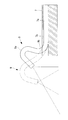
また、図8に示されるように、内視鏡9の湾曲部9a,9bを同じ方向に90°湾曲させることにより、挿入部本体7の挿入方向とは逆の方向にある患部や体腔内側面Bに対しても視野を確保し、治療を行うことができるようになっている。
また、本実施形態においては挿入部本体7の先端に、先端面から長手方向に所定の長さにわたって貫通孔7aを半径方向外方に切り欠いて形成された切欠7bを備えている。貫通孔7aは挿入部本体7の中心軸に対して偏心した位置に設けられており、切欠7bは貫通孔7aを挟んで挿入部本体7の中心軸とは反対側に向かって形成されている。切欠7bの幅寸法は、内視鏡9の外径寸法より大きく形成されている。
これにより、内視鏡9は、直線状に延ばした状態とすれば図7に示されるように貫通孔7a内に収容されることはもちろんのこと、図9に鎖線で示されるように、先端の湾曲部9a,9bを湾曲させたままの状態でも、切欠7b側に湾曲しさえすれば、切欠7bを介して挿入部本体7の半径方向外方に突出させることができるようになっている。
すなわち、内視鏡9の湾曲部9a,9bをS字状に湾曲させた状態に固定して、内視鏡9を貫通孔7aの長手方向に進退させることにより、図9に示されるように、挿入部本体7の先端面近傍に配置される視界を挿入部本体7の長手方向に平行移動させることができる。また、図10に示されるように、内視鏡9を貫通孔7aの長手方向に進退させながら、2つの湾曲部9a,9bの湾曲角度を変更することにより、同一部位に対する視点を変化させることができるようになっている。
第1の屈曲関節11、中間ロール関節12および第2の屈曲関節13は、それぞれ図5および図6に示されるようにワイヤ17a,18a,19aによって駆動されるようになっている。各ワイヤ17a,18a,19aは挿入部本体7内部を経由して挿入部本体7の基端側まで延びている。そして、ワイヤ17a,18a,19aは、挿入部本体7の基端側に取り付けられた中継部20を経由して、コントローラ5に配置された駆動部に接続され、挿入部本体7の長手方向に押し引きされるようになっている。
また、図2に示されるように、中継部20には処置具ポート21が設けられており、挿入部本体7の先端面から突出する処置具10が処置具ポート21を経由して、挿入部本体7の鉗子チャネル7b内に挿入されるようになっている。
また、内視鏡9は挿入部本体7の基端側から突出する基端部に図示しない操作部を備えており、操作部の操作によって湾曲部9a,9bを任意の方向に湾曲させることができるようになっている。
また、内視鏡9は挿入部本体7の基端側から突出する基端部に図示しない操作部を備えており、操作部の操作によって湾曲部9a,9bを任意の方向に湾曲させることができるようになっている。
このように構成された本実施形態に係る治療用マニピュレータ2およびマニピュレータシステム1の作用について以下に説明する。
本実施形態に係るマニピュレータシステム1を用いて患者Pの体腔内の治療を行うには、図7に示されるように、治療用マニピュレータ2の挿入部本体7の先端面に突出する2本のアーム8の屈曲関節11を180°付近まで屈曲させ、中間ロール関節12をアーム8が挿入部本体7の外径内側に収納されるような角度にローリングさせ、第2の屈曲関節13を真っ直ぐに延ばし、内視鏡9の湾曲部9a,9bを真っ直ぐに延ばした状態で、患者Pの体腔、例えば、肛門内に挿入していく。
本実施形態に係るマニピュレータシステム1を用いて患者Pの体腔内の治療を行うには、図7に示されるように、治療用マニピュレータ2の挿入部本体7の先端面に突出する2本のアーム8の屈曲関節11を180°付近まで屈曲させ、中間ロール関節12をアーム8が挿入部本体7の外径内側に収納されるような角度にローリングさせ、第2の屈曲関節13を真っ直ぐに延ばし、内視鏡9の湾曲部9a,9bを真っ直ぐに延ばした状態で、患者Pの体腔、例えば、肛門内に挿入していく。
そして、挿入部本体7の先端が患部近傍に配置されたところで、操作者Aがマスタ装置4を操作して、2本のアーム8を作動させるとともに、内視鏡9の操作部を操作して患部およびアーム8の先端のエンドエフェクタ8aを観察できる位置に視野を配置する。内視鏡9により撮影された映像は、モニタ6に表示され、操作者Aはモニタ6を確認しながら、マスタ装置4および内視鏡9の操作部を操作する。
2本のアーム8はそれぞれ、長手方向に間隔をあけて2つの屈曲関節11,13を有しているので、2つの屈曲関節11,13を逆方向に屈曲させて、図11に示されるようなスカラアーム状にエンドエフェクタ8aを進退させることができる。
このとき、第1の屈曲関節については片側に170°の揺動角度範囲を有しているので、エンドエフェクタをアームに対して完全に折り返すように屈曲させ、エンドエフェクタの先端を挿入部本体の先端面近傍まで近接させることができる。
このとき、第1の屈曲関節については片側に170°の揺動角度範囲を有しているので、エンドエフェクタをアームに対して完全に折り返すように屈曲させ、エンドエフェクタの先端を挿入部本体の先端面近傍まで近接させることができる。
そして、この場合に、図11に実線で示されるように、2本のアーム8の第1の屈曲関節11および第2の屈曲関節13をそれぞれ逆方向に屈曲させることにより、内視鏡9の視野範囲R内にエンドエフェクタ8aを配置し、アーム8を視野範囲R外に配置でき、アーム8が視野の邪魔にならないようにすることができる。
さらに、このようにして挿入部本体7の先端面近傍に配置したエンドエフェクタ8aの先端は、中間ロール関節12を回転させることにより、第1の屈曲関節11によるエンドエフェクタ8aの動作平面(図11の紙面に沿う平面)に交差する方向(図11の紙面に交差する方向)に移動させることができる。
さらに、このようにして挿入部本体7の先端面近傍に配置したエンドエフェクタ8aの先端は、中間ロール関節12を回転させることにより、第1の屈曲関節11によるエンドエフェクタ8aの動作平面(図11の紙面に沿う平面)に交差する方向(図11の紙面に交差する方向)に移動させることができる。
この場合に、中間ロール関節12を第1の屈曲関節11と第2の屈曲関節13との間に配置したので、第2の屈曲関節13より基端側に配置したロール関節を有する従来の場合と比較して、中間ロール関節12の回転によって動作するアーム8部分が短くて済み、回転半径を小さくして周囲の組織との干渉を低減することができるという利点がある。
また、エンドエフェクタ8aを駆動するためのワイヤ16aは、第1の屈曲関節11の2つの軸線A2,A4回りに揺動可能に配置した揺動部材14,15の内部の通路14a、15aに挿通させたシース16b内に挿入されているので、第1の屈曲関節11を170°屈曲させた状態と、真っ直ぐに延ばした状態とでは通路14a,15a内におけるシース16bの弛みが変化する。揺動部材14,15の内部の通路14a,15aは十分に広い幅を有しているのでいずれの状態においてもシース16bを収容状態にすることができる。
したがって、ワイヤ16aがアーム8の外側に突出して視界を妨げることを防止することができる。また、ワイヤ16aに張力がかけられたときには、ワイヤ16aから受ける力によって揺動部材14,15を受動的に揺動させることで、ワイヤ16aに無理な力がかからないようにすることができる。
また、本実施形態に係る治療用マニピュレータ2によれば、挿入部本体7の先端面から所定の長さにわたって切欠7bが設けられているので、湾曲部9a,9bを湾曲させて患部を観察している内視鏡9を湾曲させたままの状態で、貫通孔7aの長手方向に移動させ、視野範囲Rを平行移動させることができる。特に、挿入部本体7の先端面に近接する位置に配置されている患部を観察する際に効果的である。
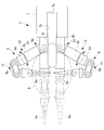
なお、本実施形態においては、2つの屈曲関節11,13とその間に配置される中間ロール関節12とを有するアーム8を例示して説明したが、図12に示されるように、第2の屈曲関節13よりもさらに基端側に、固定部8bに対してリンク8fを軸線A5回りに回転させる基端側ロール関節22を備えていてもよい。図12の矢印Bに示されるように、基端側ロール関節22を回転させることにより、屈曲している第1の屈曲関節11を固定部8bの軸線A5回りに回転させることができる。
図11の説明では2つのアーム8の第1の屈曲関節11および第2の屈曲関節13を逆方向に屈曲させて第1の屈曲関節11が両肘を張るように配置されていたが、基端側ロール関節22の回転によって、両肘を立ててすぼめるようにしてコンパクトに折りたたむことができる。その結果、アーム8が視野を邪魔しない範囲で第1の屈曲関節11どうしを近接させて、アーム8と周囲の体腔内壁との接触を低減することができる。
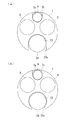
また、本実施形態においては、挿入部本体7に設けられた貫通孔からなる鉗子チャネル7bを介して処置具10を導入することとしたが、これに代えて、図13に示されるように、挿入部本体7の外周面に開口する開口部23aを有する案内溝23が挿入部本体7の全長にわたって設けられていてもよい。案内溝23の開口部23aの幅寸法は、観察用の内視鏡(ガイド部材)24(図14参照。)を挿入可能な幅寸法である。
このようにすることで、治療用マニピュレータ2の体腔内への挿入に先立って、まず、観察用の内視鏡24を体腔内に導入し、体腔内を観察しながら、患部の近傍に先端を配置した状態の観察用の内視鏡24の患者Pの体外に配置されている部分を案内溝23内に開口部23aから収容することにより、観察用の内視鏡24をガイドとして治療用マニピュレータ2を患者Pの体腔内により容易に導入していくことができる。
この場合において、挿入部本体7の外周面に開口部23aを有する案内溝23を設けることにより、先端部を体腔内に挿入状態に配置している観察用の内視鏡24の体外に露出している部分の、長手方向の途中位置に挿入部本体7を装着することができ、観察用の内視鏡24を体腔内から取り出すことなく治療用マニピュレータ2を体腔内に挿入していくことができるという利点がある。
案内溝23は図14(a)に示されるように最大幅で開口していてもよいし、図14(b)に示されるように開口部23aの幅が最大幅より小さくてもよい。柔軟な素材からなる挿入部本体7の開口部23aを押し広げながら観察用の内視鏡24を案内溝23内に収容することにより、内視鏡24をガイドとした治療用マニピュレータ2の挿入中に、治療用マニピュレータ2が内視鏡24から外れてしまうことを防止することができる。
また、本実施形態においては、第1の屈曲関節11の屈曲角度を片側に170°としたが、これに限定されるものではなく少なくとも片側に90°以上であればよい。また、第2の屈曲関節13の角度範囲を±90°としたが、これに代えて任意の角度範囲に湾曲可能であればよい。
A 操作者
A1 長手軸
A2 第1の軸線
A3 第2の軸線
R 視野範囲
1 マニピュレータシステム
2 治療用マニピュレータ
3 スレーブ装置
4 マスタ装置
5 コントローラ
7 挿入部本体
7a 貫通孔
7b 切欠
8 アーム
8a エンドエフェクタ
9 内視鏡
11 第1の屈曲関節
12 中間ロール関節
13 第2の屈曲関節
14,15 揺動部材
16a ワイヤ(駆動用線材)
22 基端側ロール関節
23 案内溝
23a 開口部
A1 長手軸
A2 第1の軸線
A3 第2の軸線
R 視野範囲
1 マニピュレータシステム
2 治療用マニピュレータ
3 スレーブ装置
4 マスタ装置
5 コントローラ
7 挿入部本体
7a 貫通孔
7b 切欠
8 アーム
8a エンドエフェクタ
9 内視鏡
11 第1の屈曲関節
12 中間ロール関節
13 第2の屈曲関節
14,15 揺動部材
16a ワイヤ(駆動用線材)
22 基端側ロール関節
23 案内溝
23a 開口部
Claims (8)
- 挿入部本体と、
該挿入部本体の先端面から前方に突出するように設けられ、先端にエンドエフェクタを有する少なくとも1本のアームと、
前記挿入部本体に設けられ、前記アーム先端の前記エンドエフェクタを観察可能な視野範囲を有する内視鏡とを備え、
前記アームが、前記先端側から順に、該アームの長手軸に直交する第1の軸線回りに前記エンドエフェクタを揺動可能な第1の屈曲関節と、前記長手軸回りに回転可能な中間ロール関節と、前記長手軸に直交する第2の軸線回りに揺動可能な第2の屈曲関節とを備え、
前記第1の屈曲関節が、前記長手軸に対して少なくとも片側に90°以上屈曲可能である治療用マニピュレータ。 - 前記挿入部本体に、該挿入部本体の長手方向に沿って貫通して前記先端面に開口し、前記内視鏡を移動可能に収容する貫通孔が設けられ、
該貫通孔に、前記先端面の開口から所定の長さ範囲にわたって前記内視鏡の外径寸法より大きな幅寸法を有する切欠が設けられている請求項1に記載の治療用マニピュレータ。 - 前記エンドエフェクタを駆動する駆動用線材が、前記アームを構成している各関節の内部を貫通して配置されている請求項1または請求項2に記載の治療用マニピュレータ。
- 前記第1の屈曲関節が、前記長手軸線に対して片側のみに90°以上屈曲可能であり、
該第1の屈曲関節内に前記駆動用線材を貫通させる通路を有し、湾曲する前記駆動用線材の動作に応じて、前記第1の屈曲関節の屈曲中心回りに受動的に揺動可能に設けられた揺動部材を備える請求項3に記載の治療用マニピュレータ。 - 前記第2の屈曲関節よりも基端側に、前記長手軸回りに回転可能な基端側ロール関節を備える請求項1から請求項4のいずれかに記載の治療用マニピュレータ。
- 前記挿入部本体の外面に、長手方向に沿って設けられるとともに、径方向外方に開口する開口部を有し、管状のガイド部材を前記開口部を介して径方向外方から挿入可能な案内溝が設けられている請求項1から請求項5のいずれかに記載の治療用マニピュレータ。
- 請求項1から請求項6のいずれかに記載の治療用マニピュレータと、該治療用マニピュレータを駆動する駆動部とを備えるスレーブ装置と、
操作者により操作される操作部を備えるマスタ装置と、
該マスタ装置の前記操作部により入力された入力信号に基づいて前記スレーブ装置の駆動部を制御するコントローラとを備えるマニピュレータシステム。 - 前記コントローラが、前記マスタ装置からの入力信号に基づいて前記スレーブ装置の各前記関節の動作指令信号を生成する際に、前記第1の屈曲関節が内視鏡画像の中心からより離れた位置に配置されるように、各前記関節の動作指令信号を算出する請求項7に記載のマニピュレータシステム。
Priority Applications (3)
| Application Number | Priority Date | Filing Date | Title |
|---|---|---|---|
| EP14830236.7A EP3025674B1 (en) | 2013-07-26 | 2014-06-24 | Therapeutic manipulator and manipulator system |
| CN201480040754.8A CN105392437B (zh) | 2013-07-26 | 2014-06-24 | 治疗用机械手和机械手系统 |
| US15/004,435 US20160135911A1 (en) | 2013-07-26 | 2016-01-22 | Treatment manipulator and manipulator system |
Applications Claiming Priority (2)
| Application Number | Priority Date | Filing Date | Title |
|---|---|---|---|
| JP2013-155883 | 2013-07-26 | ||
| JP2013155883A JP6116429B2 (ja) | 2013-07-26 | 2013-07-26 | 治療用マニピュレータおよびマニピュレータシステム |
Related Child Applications (1)
| Application Number | Title | Priority Date | Filing Date |
|---|---|---|---|
| US15/004,435 Continuation US20160135911A1 (en) | 2013-07-26 | 2016-01-22 | Treatment manipulator and manipulator system |
Publications (1)
| Publication Number | Publication Date |
|---|---|
| WO2015012044A1 true WO2015012044A1 (ja) | 2015-01-29 |
Family
ID=52393096
Family Applications (1)
| Application Number | Title | Priority Date | Filing Date |
|---|---|---|---|
| PCT/JP2014/066634 WO2015012044A1 (ja) | 2013-07-26 | 2014-06-24 | 治療用マニピュレータおよびマニピュレータシステム |
Country Status (5)
| Country | Link |
|---|---|
| US (1) | US20160135911A1 (ja) |
| EP (1) | EP3025674B1 (ja) |
| JP (1) | JP6116429B2 (ja) |
| CN (1) | CN105392437B (ja) |
| WO (1) | WO2015012044A1 (ja) |
Cited By (1)
| Publication number | Priority date | Publication date | Assignee | Title |
|---|---|---|---|---|
| CN108366836A (zh) * | 2015-10-16 | 2018-08-03 | 医疗显微器具股份公司 | 手术工具 |
Families Citing this family (10)
| Publication number | Priority date | Publication date | Assignee | Title |
|---|---|---|---|---|
| CA2957624C (en) | 2014-09-04 | 2023-09-26 | Memic Innovative Surgery Ltd. | Method and devices for hysterectomy |
| SI3190942T1 (sl) | 2015-09-04 | 2020-10-30 | Memic Innovative Surgery Ltd. | Aktiviranje naprave, ki obsega mehanske roke |
| EP3219283B1 (en) | 2016-03-09 | 2020-12-02 | Memic Innovative Surgery Ltd. | Modular surgical device comprising mechanical arms |
| CN108066010B (zh) * | 2016-11-10 | 2024-04-30 | 香港大学深圳研究院 | 一种具有柔性和多自由度的手术机器人 |
| US10973592B2 (en) | 2017-03-09 | 2021-04-13 | Memie Innovative Surgery Ltd. | Control console for surgical device with mechanical arms |
| US11779410B2 (en) | 2017-03-09 | 2023-10-10 | Momentis Surgical Ltd | Control console including an input arm for control of a surgical mechanical arm |
| JP7085400B2 (ja) | 2018-04-27 | 2022-06-16 | 川崎重工業株式会社 | 外科手術システム |
| CN109464192B (zh) * | 2018-12-29 | 2023-11-14 | 黄振宇 | 一种三维控弯的机械臂 |
| JP2020141833A (ja) * | 2019-03-06 | 2020-09-10 | 川崎重工業株式会社 | 外科手術システムの制御方法および外科手術システム |
| WO2021176531A1 (ja) * | 2020-03-02 | 2021-09-10 | リバーフィールド株式会社 | 手術ロボット |
Citations (7)
| Publication number | Priority date | Publication date | Assignee | Title |
|---|---|---|---|---|
| US5813976A (en) * | 1996-04-02 | 1998-09-29 | Filipi; Charles J. | Stabilizing instrumentation for the performing of endoscopic surgical procedures |
| JP2003204968A (ja) * | 2002-01-11 | 2003-07-22 | Olympus Optical Co Ltd | 治療装置 |
| JP2004122286A (ja) * | 2002-10-02 | 2004-04-22 | Hitachi Ltd | マニピュレータ |
| JP2009539573A (ja) * | 2006-06-13 | 2009-11-19 | インテュイティブ サージカル インコーポレイテッド | 低侵襲性外科手術用システム |
| JP2010057914A (ja) | 2008-09-02 | 2010-03-18 | Olympus Medical Systems Corp | 医療用マニピュレータ、処置システム |
| US20100331856A1 (en) * | 2008-12-12 | 2010-12-30 | Hansen Medical Inc. | Multiple flexible and steerable elongate instruments for minimally invasive operations |
| JP2012055996A (ja) * | 2010-09-07 | 2012-03-22 | Olympus Corp | マスタスレーブマニピュレータ |
Family Cites Families (9)
| Publication number | Priority date | Publication date | Assignee | Title |
|---|---|---|---|---|
| US8004229B2 (en) * | 2005-05-19 | 2011-08-23 | Intuitive Surgical Operations, Inc. | Software center and highly configurable robotic systems for surgery and other uses |
| US6340344B1 (en) * | 2000-07-18 | 2002-01-22 | Evergreen Medical Incorporated | Endoscope with a removable suction tube |
| US6902560B1 (en) * | 2000-07-27 | 2005-06-07 | Intuitive Surgical, Inc. | Roll-pitch-roll surgical tool |
| EP1531749A2 (en) * | 2002-08-13 | 2005-05-25 | Microbotics Corporation | Microsurgical robot system |
| CN2614044Y (zh) * | 2003-05-06 | 2004-05-05 | 马增山 | 医用机械手 |
| US20050096502A1 (en) * | 2003-10-29 | 2005-05-05 | Khalili Theodore M. | Robotic surgical device |
| US9204923B2 (en) * | 2008-07-16 | 2015-12-08 | Intuitive Surgical Operations, Inc. | Medical instrument electronically energized using drive cables |
| KR20130132109A (ko) * | 2012-05-25 | 2013-12-04 | 삼성전자주식회사 | 서포터 장치 및 이를 채용한 수술 로봇 시스템 |
| CN104883991B (zh) * | 2012-09-19 | 2018-08-28 | 南洋理工大学 | 柔性主从式机器人内窥镜检查系统 |
-
2013
- 2013-07-26 JP JP2013155883A patent/JP6116429B2/ja active Active
-
2014
- 2014-06-24 WO PCT/JP2014/066634 patent/WO2015012044A1/ja active Application Filing
- 2014-06-24 EP EP14830236.7A patent/EP3025674B1/en active Active
- 2014-06-24 CN CN201480040754.8A patent/CN105392437B/zh active Active
-
2016
- 2016-01-22 US US15/004,435 patent/US20160135911A1/en not_active Abandoned
Patent Citations (8)
| Publication number | Priority date | Publication date | Assignee | Title |
|---|---|---|---|---|
| US5813976A (en) * | 1996-04-02 | 1998-09-29 | Filipi; Charles J. | Stabilizing instrumentation for the performing of endoscopic surgical procedures |
| JP2003204968A (ja) * | 2002-01-11 | 2003-07-22 | Olympus Optical Co Ltd | 治療装置 |
| JP2004122286A (ja) * | 2002-10-02 | 2004-04-22 | Hitachi Ltd | マニピュレータ |
| JP2009539573A (ja) * | 2006-06-13 | 2009-11-19 | インテュイティブ サージカル インコーポレイテッド | 低侵襲性外科手術用システム |
| US8057385B2 (en) | 2006-06-13 | 2011-11-15 | Intuitive Surgical Operations, Inc. | Side looking minimally invasive surgery instrument assembly |
| JP2010057914A (ja) | 2008-09-02 | 2010-03-18 | Olympus Medical Systems Corp | 医療用マニピュレータ、処置システム |
| US20100331856A1 (en) * | 2008-12-12 | 2010-12-30 | Hansen Medical Inc. | Multiple flexible and steerable elongate instruments for minimally invasive operations |
| JP2012055996A (ja) * | 2010-09-07 | 2012-03-22 | Olympus Corp | マスタスレーブマニピュレータ |
Non-Patent Citations (1)
| Title |
|---|
| See also references of EP3025674A4 |
Cited By (2)
| Publication number | Priority date | Publication date | Assignee | Title |
|---|---|---|---|---|
| CN108366836A (zh) * | 2015-10-16 | 2018-08-03 | 医疗显微器具股份公司 | 手术工具 |
| CN108366836B (zh) * | 2015-10-16 | 2021-08-27 | 医疗显微器具股份公司 | 手术工具 |
Also Published As
| Publication number | Publication date |
|---|---|
| EP3025674A1 (en) | 2016-06-01 |
| EP3025674A4 (en) | 2017-03-29 |
| JP2015024034A (ja) | 2015-02-05 |
| US20160135911A1 (en) | 2016-05-19 |
| JP6116429B2 (ja) | 2017-04-19 |
| EP3025674B1 (en) | 2018-08-01 |
| CN105392437B (zh) | 2018-02-06 |
| CN105392437A (zh) | 2016-03-09 |
Similar Documents
| Publication | Publication Date | Title |
|---|---|---|
| JP6116429B2 (ja) | 治療用マニピュレータおよびマニピュレータシステム | |
| RU2551932C2 (ru) | Минимально инвазивные лапароскопические хирургические щипцы | |
| JP5197980B2 (ja) | 多関節湾曲機構及び多関節湾曲機構を備えた医療器具 | |
| US8347757B2 (en) | Method and apparatus for reducing at least one friction force opposing an axial force exerted through an actuator element | |
| US20180214220A1 (en) | Surgical robot | |
| JP7148242B2 (ja) | 手術用ロボット | |
| JP5111612B2 (ja) | 小口径腹腔鏡手術装置 | |
| WO2015029804A1 (ja) | 医療用マニピュレータ | |
| EP3320873A1 (en) | Surgical robot | |
| JP6214464B2 (ja) | 内視鏡システム | |
| JP6300801B2 (ja) | 医療用マニピュレータおよび医療用マニピュレータの制御方法 | |
| WO2017216835A1 (ja) | 医療用デバイス | |
| WO2015012066A1 (ja) | マニピュレータおよびマニピュレータシステム | |
| CN108066010B (zh) | 一种具有柔性和多自由度的手术机器人 | |
| JP2008220972A (ja) | 処置具 | |
| JP4145309B2 (ja) | 処置具 | |
| JP2008220971A (ja) | 処置具 | |
| WO2011152113A1 (ja) | 駆動力伝達機構及びマニピュレータシステム | |
| JP6203132B2 (ja) | ガイド装置および手術システム | |
| JPH0397431A (ja) | 内視鏡装置 | |
| WO2014007113A1 (ja) | 医療用マニピュレータ | |
| WO2012073738A1 (ja) | 医療用処置具およびマニピュレータ | |
| JP2005230184A (ja) | 医療用具 | |
| KR100994373B1 (ko) | 수술용 인스트루먼트 | |
| JP2022191607A (ja) | 医療器具および手術システム |
Legal Events
| Date | Code | Title | Description |
|---|---|---|---|
| WWE | Wipo information: entry into national phase |
Ref document number: 201480040754.8 Country of ref document: CN |
|
| 121 | Ep: the epo has been informed by wipo that ep was designated in this application |
Ref document number: 14830236 Country of ref document: EP Kind code of ref document: A1 |
|
| NENP | Non-entry into the national phase |
Ref country code: DE |
|
| WWE | Wipo information: entry into national phase |
Ref document number: 2014830236 Country of ref document: EP |