WO2015012044A1 - Manipulateur thérapeutique et système de manipulateur - Google Patents
Manipulateur thérapeutique et système de manipulateur Download PDFInfo
- Publication number
- WO2015012044A1 WO2015012044A1 PCT/JP2014/066634 JP2014066634W WO2015012044A1 WO 2015012044 A1 WO2015012044 A1 WO 2015012044A1 JP 2014066634 W JP2014066634 W JP 2014066634W WO 2015012044 A1 WO2015012044 A1 WO 2015012044A1
- Authority
- WO
- WIPO (PCT)
- Prior art keywords
- joint
- main body
- arm
- manipulator
- bending
- Prior art date
Links
Images


Classifications
-
- A—HUMAN NECESSITIES
- A61—MEDICAL OR VETERINARY SCIENCE; HYGIENE
- A61B—DIAGNOSIS; SURGERY; IDENTIFICATION
- A61B34/00—Computer-aided surgery; Manipulators or robots specially adapted for use in surgery
- A61B34/30—Surgical robots
-
- A—HUMAN NECESSITIES
- A61—MEDICAL OR VETERINARY SCIENCE; HYGIENE
- A61B—DIAGNOSIS; SURGERY; IDENTIFICATION
- A61B34/00—Computer-aided surgery; Manipulators or robots specially adapted for use in surgery
- A61B34/30—Surgical robots
- A61B34/37—Master-slave robots
-
- A—HUMAN NECESSITIES
- A61—MEDICAL OR VETERINARY SCIENCE; HYGIENE
- A61B—DIAGNOSIS; SURGERY; IDENTIFICATION
- A61B1/00—Instruments for performing medical examinations of the interior of cavities or tubes of the body by visual or photographical inspection, e.g. endoscopes; Illuminating arrangements therefor
- A61B1/00064—Constructional details of the endoscope body
- A61B1/00071—Insertion part of the endoscope body
- A61B1/0008—Insertion part of the endoscope body characterised by distal tip features
- A61B1/00087—Tools
-
- A—HUMAN NECESSITIES
- A61—MEDICAL OR VETERINARY SCIENCE; HYGIENE
- A61B—DIAGNOSIS; SURGERY; IDENTIFICATION
- A61B1/00—Instruments for performing medical examinations of the interior of cavities or tubes of the body by visual or photographical inspection, e.g. endoscopes; Illuminating arrangements therefor
- A61B1/00147—Holding or positioning arrangements
- A61B1/00149—Holding or positioning arrangements using articulated arms
-
- A—HUMAN NECESSITIES
- A61—MEDICAL OR VETERINARY SCIENCE; HYGIENE
- A61B—DIAGNOSIS; SURGERY; IDENTIFICATION
- A61B34/00—Computer-aided surgery; Manipulators or robots specially adapted for use in surgery
- A61B34/70—Manipulators specially adapted for use in surgery
-
- A—HUMAN NECESSITIES
- A61—MEDICAL OR VETERINARY SCIENCE; HYGIENE
- A61B—DIAGNOSIS; SURGERY; IDENTIFICATION
- A61B17/00—Surgical instruments, devices or methods, e.g. tourniquets
- A61B17/28—Surgical forceps
- A61B17/29—Forceps for use in minimally invasive surgery
- A61B2017/2901—Details of shaft
- A61B2017/2906—Multiple forceps
-
- A—HUMAN NECESSITIES
- A61—MEDICAL OR VETERINARY SCIENCE; HYGIENE
- A61B—DIAGNOSIS; SURGERY; IDENTIFICATION
- A61B17/00—Surgical instruments, devices or methods, e.g. tourniquets
- A61B17/28—Surgical forceps
- A61B17/29—Forceps for use in minimally invasive surgery
- A61B2017/2926—Details of heads or jaws
- A61B2017/2927—Details of heads or jaws the angular position of the head being adjustable with respect to the shaft
-
- A—HUMAN NECESSITIES
- A61—MEDICAL OR VETERINARY SCIENCE; HYGIENE
- A61B—DIAGNOSIS; SURGERY; IDENTIFICATION
- A61B34/00—Computer-aided surgery; Manipulators or robots specially adapted for use in surgery
- A61B34/30—Surgical robots
- A61B2034/301—Surgical robots for introducing or steering flexible instruments inserted into the body, e.g. catheters or endoscopes
-
- A—HUMAN NECESSITIES
- A61—MEDICAL OR VETERINARY SCIENCE; HYGIENE
- A61B—DIAGNOSIS; SURGERY; IDENTIFICATION
- A61B34/00—Computer-aided surgery; Manipulators or robots specially adapted for use in surgery
- A61B34/30—Surgical robots
- A61B2034/305—Details of wrist mechanisms at distal ends of robotic arms
- A61B2034/306—Wrists with multiple vertebrae
-
- A—HUMAN NECESSITIES
- A61—MEDICAL OR VETERINARY SCIENCE; HYGIENE
- A61B—DIAGNOSIS; SURGERY; IDENTIFICATION
- A61B90/00—Instruments, implements or accessories specially adapted for surgery or diagnosis and not covered by any of the groups A61B1/00 - A61B50/00, e.g. for luxation treatment or for protecting wound edges
- A61B90/36—Image-producing devices or illumination devices not otherwise provided for
- A61B90/37—Surgical systems with images on a monitor during operation
- A61B2090/373—Surgical systems with images on a monitor during operation using light, e.g. by using optical scanners
Definitions
- the present invention relates to a therapeutic manipulator and a manipulator system.
- a therapeutic manipulator having two arms provided with two curved portions adjacent to the distal end of the insertion portion in the longitudinal direction is known (for example, see Patent Document 1).
- a treatment manipulator having an arm having two bending joints adjacent to each other in the longitudinal direction and a roll joint arranged on the base end side thereof is known in order to perform treatment on the side of the insertion portion ( For example, see Patent Document 2.)
- the joint on the distal end side that changes the direction of the treatment tool is curved with a gentle curve, so that it is possible to treat the affected part disposed in the vicinity of the insertion portion main body. There is an inconvenience that it cannot be done.
- the root roll joint in order to move the distal treatment tool in a direction intersecting the movement direction by the bending joint, the root roll joint must be operated, and almost the entire treatment manipulator is operated. Has a disadvantage in that it moves and comes into contact with surrounding tissues.
- the present invention has been made in view of the above-described circumstances, and is a therapeutic manipulator and a manipulator capable of treating an affected part disposed at a position close to the insertion portion main body while reducing interference with surrounding tissues and the like.
- the purpose is to provide a system.
- the present invention provides the following means.
- One aspect of the present invention is provided in the insertion portion main body, at least one arm provided to protrude forward from the distal end surface of the insertion portion main body, and having an end effector at the distal end, and the insertion portion main body.
- An endoscope having a field-of-view range in which the end effector at the distal end of the arm can be observed, and the arm is arranged in order from the distal end side around the first axis perpendicular to the longitudinal axis of the arm.
- a therapeutic manipulator in which a first bending joint can be bent at least 90 ° to at least one side with respect to the longitudinal axis.
- the arm when the insertion portion main body is inserted into the body cavity from the distal end surface side, the arm is disposed so as to protrude forward from the distal end surface, and treatment with the arm can be performed on the inner body wall in front of the insertion portion.
- the first bendable joint that is bendable at 90 ° or more arranged on the distal end side allows easy access to a portion disposed at a position close to the distal end surface of the apparatus main body and performs treatment by the end effector at the distal end. Can be applied.
- the end effector treating the part close to the apparatus main body in a state where the first bending joint is bent in the body cavity is moved in a direction intersecting the bending plane by the first bending joint.
- Rotate the intermediate roll joint When the intermediate roll joint arranged between the first flex joint and the second flex joint is rotated, only the first flex joint and the end effector arranged on the tip side of the intermediate roll joint are rotated. It is possible to reduce the radius of rotation and reduce the interference between the surrounding tissue and the arm.
- the insertion portion main body is provided with a through hole that penetrates along the longitudinal direction of the insertion portion main body and opens at the distal end surface, and movably accommodates the endoscope. Further, a notch having a width dimension larger than the outer diameter dimension of the endoscope may be provided over a predetermined length range from the opening of the distal end surface.
- the insertion portion main body is inserted into the body cavity while the endoscope is accommodated in the through hole provided in the insertion portion main body, and is accommodated in the through hole in the vicinity of the treatment site.
- the endoscope By moving the formed endoscope in the longitudinal direction of the through-hole, the endoscope can be advanced and retracted in the longitudinal direction and protruded from the opening on the distal end surface of the insertion portion main body.
- the protruded endoscope can bend the bending portion provided in the endoscope so as to direct the field of view in a desired direction, and observe the end effector arranged at the tip of the arm.
- the endoscope protruded from the opening of the distal end surface of the insertion portion main body is curved and is retracted in the longitudinal direction of the through hole
- the intermediate position in the length direction of the endoscope is By being accommodated in the notch provided at the tip of the through hole, the endoscope in the through hole can be protruded outward in the radial direction of the insertion portion main body through the notch. Therefore, the endoscope can be advanced and retracted while the bending portion is curved, and the visual field range can be advanced and retracted, and the same observation site can be observed while changing the angle.
- the drive wire which drives the said end effector may be arrange
- the first bending joint can be bent at 90 ° or more only on one side with respect to the longitudinal axis, and there is a passage through which the driving wire rod passes through the first bending joint.
- a swinging member provided so as to be passively swingable around the bending center of the first bending joint may be provided in accordance with the operation of the curved driving wire.
- the slack of the driving wire disposed in the passage in the first bending joint can be minimized, and the swinging member can be swung passively following the movement of the driving wire. By doing so, it is not necessary to apply an excessive load to the drive wire. Accordingly, even if the first bending joint is swung between a state in which the first bending joint is extended in the direction along the longitudinal axis and a state in which the first bending joint is bent by 90 ° or more on one side, the driving wire rod is loosened in the radial direction of the arm. It is possible to prevent the kink from protruding outward or being subjected to an excessive load.
- a tubular guide member is radial direction through the said opening part.
- a guide groove that can be inserted from the outside may be provided.
- a slave device including any one of the above-described treatment manipulators, a drive unit that drives the treatment manipulator, a master device including an operation unit operated by an operator,
- a manipulator system comprising: a controller that controls a drive unit of the slave device based on an input signal input by the operation unit of a master device.
- the controller when the controller generates an operation command signal for each joint of the slave device based on an input signal from the master device, the first bending joint is moved from the center of the endoscopic image. You may calculate the operation command signal of each said joint so that it may arrange
- FIG. 1 It is a whole lineblock diagram showing a manipulator system provided with a manipulator for treatment concerning one embodiment of the present invention. It is a perspective view which shows the manipulator for a treatment which concerns on one Embodiment of this invention with which the manipulator system of FIG. 1 is equipped. It is a perspective view which shows the arm with which the treatment manipulator of FIG. 2 was equipped. It is a schematic diagram which shows the axial structure of the arm of FIG. It is a schematic diagram which shows the internal structure of the state extended in the linear form of the arm of FIG.
- FIG. 4 is a schematic diagram showing an internal structure in a state where a first bending joint of the arm of FIG. 3 is bent.
- a manipulator system 1 includes a treatment manipulator 2 according to this embodiment that is inserted into a body cavity of a patient P and a slave device 3 that includes a drive unit (not shown). Obtained by the master device 4 having an operation unit operated by the operator A, the controller 5 that controls the drive unit of the slave device 3 based on an input signal by the operation of the master device 4, and the treatment manipulator 2. And a monitor 6 for displaying an image.
- the treatment manipulator 2 includes a flexible tubular insertion portion main body 7 and two arms 8 provided to project forward from the distal end surface of the insertion portion main body 7. And an endoscope 9 movably accommodated in a through hole 7a (see FIG. 7) provided along the longitudinal direction of the insertion portion main body 7.
- the broken line is an enlarged view of the distal end portion of the insertion portion main body 7, and reference numeral 10 is introduced through a forceps channel 7 b (see FIG. 7) provided along the longitudinal direction of the insertion portion main body 7.
- the treatment tool arranged in a protruding manner is shown.
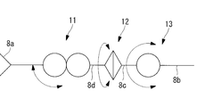
- the two arms 8 are bent around the end effector 8a such as a grasping forceps and the axis A2 orthogonal to the longitudinal axis A1 in order from the distal end side along the longitudinal axis direction.
- a possible first bending joint 11, an intermediate roll joint 12 that can rotate about the longitudinal axis A 1, and a second bending joint 13 that can be bent about an axis A 3 orthogonal to the longitudinal axis A 1 are provided.
- the arm 8 is described as being fixed to the insertion portion main body 7.
- the arm 8 may protrude from a channel (not shown) of the insertion portion main body 7. The case of protruding from the channel operates in the same manner as the case of being fixed to the insertion portion main body 7.
- the second bending joint 13 has a columnar first arm portion 8c around an axis A3 orthogonal to the longitudinal axis of the fixing portion 8b with respect to the columnar fixing portion 8b fixed to the insertion portion main body 7.
- the fixed portion 8b is supported so as to be swingable over an angle range of ⁇ 90 ° with respect to the longitudinal axis of the fixed portion 8b.
- the intermediate roll joint 12 supports a columnar second arm portion 8d arranged coaxially with the first arm portion 8c so as to be rotatable by ⁇ 180 ° around the longitudinal axis A1 with respect to the first arm portion 8c. is doing.
- the first bending joint 11 connects the second arm portion 8d and the end effector 8a by a link member 8e, the link member 8e with respect to the second arm portion 8d, and the end effector 8a with respect to the link member 8e.
- the double joint type joint includes, for example, gears (not shown) that mesh with each other in the second arm portion 8d and the end effector 8a, and when the link member 8e is swung around the axis A2, This is a joint that is also swung with respect to the link member 8e when the end effector 8a is rotated about the axis A4.
- the end effector 8a can be swung at an angle larger than the swiveling angle around the axis A2, and a wide operating angle range can be realized. Yes. Thereby, the first bending joint 11 can bend the end effector 8a only over one side with respect to the longitudinal axis A1 of the second arm portion 8d over an angular range of 170 °.
- the first bending joint 11 is not limited to the double joint type described above. Specifically, even if it is a joint that can be rotated around one rotation axis without using the link member 8e. Good.
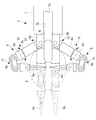
- the first bending joint 11 is provided with disk-like swinging members 14 and 15 that are supported so as to be swingable about two axes A2 and A4, respectively. Yes.
- the swing members 14 and 15 are provided with passages 14a and 15a penetrating the inside in the radial direction.
- the passages 14a and 15a have heights in the directions of the axes A2 and A4 that can accommodate the sheath 16b through which the drive wire 16a for driving the end effector 8a is inserted, and an axis A2 that is formed to be sufficiently wider than the sheath 16b. , And a width dimension in a direction orthogonal to A4.
- the drive wire 16a is not limited, and an elongated flexible rod may be used.
- reference numeral 17a is a wire for driving the first bending joint 11
- reference numeral 17b is a sheath for inserting the wire 17a
- reference numeral 18a is a wire for driving the intermediate roll joint 12
- reference numeral 18b is A sheath through which the wire 18a is inserted
- reference numeral 19a is a wire for driving the second bending joint 13
- reference numeral 19b is a sheath through which the wire 19a is inserted.
- the endoscope 9 includes an observation optical system (not shown) having a visual field range in front of the distal end surface, and has two curved portions 9a and 9b adjacent to each other with a gap in the longitudinal direction. As shown in FIG. 2, it is possible to take a linear form in which the curved parts 9a and 9b shown in FIG. 2 are extended, or an S-shaped form in which the two curved parts 9a and 9b are curved in opposite directions. ing. By taking a linear form, it can be accommodated in the through hole 7a of the insertion portion main body 7, so that smooth insertion into the body cavity can be performed. On the other hand, the visual field range can be directed to a position close to the distal end surface of the insertion portion main body 7 by taking the S-shaped form.
- the affected part or the inner surface of the body cavity in the direction opposite to the insertion direction of the insertion part main body 7 A field of view can be secured for B and treatment can be performed.
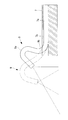
- the distal end of the insertion portion main body 7 is provided with a notch 7b formed by notching the through hole 7a radially outward from the distal end surface over a predetermined length in the longitudinal direction.
- the through hole 7a is provided at a position eccentric with respect to the central axis of the insertion portion main body 7, and the notch 7b is formed toward the side opposite to the central axis of the insertion portion main body 7 with the through hole 7a interposed therebetween.
- the width dimension of the notch 7 b is formed larger than the outer diameter dimension of the endoscope 9.
- the endoscope 9 can be accommodated in the through-hole 7a as shown in FIG. 7 as shown in FIG. Even when the curved portions 9a and 9b are curved, they can be projected outwardly in the radial direction of the insertion portion main body 7 through the notches 7b as long as they are curved toward the notches 7b. .
- the bending portions 9a and 9b of the endoscope 9 are fixed in a S-curved shape, and the endoscope 9 is advanced and retracted in the longitudinal direction of the through hole 7a, as shown in FIG.
- the field of view disposed in the vicinity of the distal end surface of the insertion portion main body 7 can be translated in the longitudinal direction of the insertion portion main body 7.
- the viewpoint of the same part can be changed by changing the bending angle of the two bending portions 9a and 9b while moving the endoscope 9 in the longitudinal direction of the through hole 7a. Can be done.
- the first bending joint 11, the intermediate roll joint 12, and the second bending joint 13 are driven by wires 17a, 18a, and 19a as shown in FIGS.
- Each wire 17a, 18a, 19a extends to the proximal end side of the insertion portion body 7 through the insertion portion body 7.
- the wires 17 a, 18 a, and 19 a are connected to the drive unit disposed in the controller 5 via the relay unit 20 attached to the proximal end side of the insertion unit main body 7, and in the longitudinal direction of the insertion unit main body 7. It is designed to be pushed and pulled.
- a treatment instrument port 21 is provided in the relay section 20, and the treatment instrument 10 protruding from the distal end surface of the insertion section main body 7 passes through the treatment instrument port 21 and is inserted into the insertion section.
- the body 7 is inserted into the forceps channel 7b.
- the endoscope 9 includes an operation unit (not shown) at a proximal end portion that protrudes from the proximal end side of the insertion portion main body 7, and the bending portions 9a and 9b can be bent in an arbitrary direction by operation of the operation portion. It can be done.
- the two arms projecting from the distal end surface of the insertion portion main body 7 of the treatment manipulator 2.
- 8 flexion joint 11 is bent to about 180 °
- intermediate roll joint 12 is rolled at an angle such that arm 8 is housed inside the outer diameter of insertion portion body 7, and second flexure joint 13 is straightened.
- the endoscope 9 is inserted into the body cavity of the patient P, for example, the anus.
- the operator A operates the master device 4 to operate the two arms 8 and operates the operation section of the endoscope 9.
- a visual field is arranged at a position where the affected part and the end effector 8a at the tip of the arm 8 can be observed.
- the video imaged by the endoscope 9 is displayed on the monitor 6, and the operator A operates the master device 4 and the operation unit of the endoscope 9 while checking the monitor 6.
- each of the two arms 8 has two bending joints 11 and 13 spaced apart in the longitudinal direction, the two bending joints 11 and 13 are bent in opposite directions, as shown in FIG.
- the end effector 8a can be advanced and retracted in the shape of a simple SCARA arm.
- the first bending joint has a swing angle range of 170 ° on one side, the end effector is bent so as to be completely folded with respect to the arm, and the end of the end effector is connected to the insertion portion main body. It can be made close to the vicinity of the tip surface.
- the first bending joint 11 and the second bending joint 13 of the two arms 8 are bent in opposite directions, respectively.
- the end effector 8a can be disposed within the visual field range R, and the arm 8 can be disposed outside the visual field range R, so that the arm 8 does not interfere with the visual field.
- the distal end of the end effector 8a arranged in the vicinity of the distal end surface of the insertion portion main body 7 in this way rotates the intermediate roll joint 12, thereby causing the operation plane of the end effector 8a by the first bending joint 11 (FIG. 11). Can be moved in a direction that intersects the plane of FIG. 11 (a direction that intersects the plane of FIG. 11).
- the intermediate roll joint 12 is disposed between the first bending joint 11 and the second bending joint 13, a conventional case having a roll joint disposed on the proximal side from the second bending joint 13.
- the arm 8 portion that is operated by the rotation of the intermediate roll joint 12 can be shortened, and the radius of rotation can be reduced to reduce interference with surrounding tissues.
- the wire 16a for driving the end effector 8a is inserted into the passages 14a and 15a in the swing members 14 and 15 disposed so as to be swingable around the two axes A2 and A4 of the first bending joint 11. Since the sheath 16b is inserted into the sheath 16b, the slackness of the sheath 16b in the passages 14a and 15a changes between the state where the first bending joint 11 is bent by 170 ° and the state where the first bending joint 11 is straightened. Since the passages 14a and 15a inside the swing members 14 and 15 have a sufficiently wide width, the sheath 16b can be accommodated in any state.
- the notch 7b is provided from the distal end surface of the insertion portion main body 7 over a predetermined length, the affected portions are observed by curving the curved portions 9a and 9b.
- the field-of-view range R can be translated in parallel by moving the endoscope 9 in the longitudinal direction of the through-hole 7a with the endoscope 9 being curved. In particular, this is effective when observing the affected part arranged at a position close to the distal end surface of the insertion portion main body 7.
- the arm 8 having the two bending joints 11 and 13 and the intermediate roll joint 12 disposed therebetween is described as an example.
- a proximal-side roll joint 22 that rotates the link 8f about the axis A5 relative to the fixed portion 8b may be further provided on the proximal side of the joint 13.
- the bent first bent joint 11 can be rotated around the axis A5 of the fixed portion 8b.
- the first bending joint 11 and the second bending joint 13 of the two arms 8 are bent in the opposite directions so that the first bending joint 11 stretches both elbows.
- both elbows can be folded up in a compact manner as if they were raised.
- the treatment instrument 10 is introduced through the forceps channel 7b formed of a through hole provided in the insertion portion main body 7.
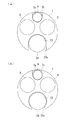
- a guide groove 23 having an opening 23 a that opens on the outer peripheral surface of the insertion portion main body 7 may be provided over the entire length of the insertion portion main body 7.
- the width dimension of the opening 23a of the guide groove 23 is a width dimension in which an observation endoscope (guide member) 24 (see FIG. 14) can be inserted.
- the endoscope 24 for observation is introduced into the body cavity, and the tip is placed near the affected area while observing the inside of the body cavity.
- a portion of the observation endoscope 24 arranged outside the body of the patient P is accommodated in the guide groove 23 from the opening 23a, thereby using the observation endoscope 24 as a guide and a therapeutic manipulator. 2 can be introduced more easily into the body cavity of the patient P.
- the distal end portion is exposed outside the body of the observation endoscope 24 disposed in the body cavity.
- the insertion portion main body 7 can be attached to a position in the middle of the longitudinal direction, and the treatment manipulator 2 can be inserted into the body cavity without removing the observation endoscope 24 from the body cavity. There is an advantage that you can.
- the guide groove 23 may be opened with the maximum width as shown in FIG. 14 (a), or the width of the opening 23a may be smaller than the maximum width as shown in FIG. 14 (b).
- the endoscope 24 for observation is accommodated in the guide groove 23 while expanding the opening 23a of the insertion portion body 7 made of a flexible material. Further, it is possible to prevent the therapeutic manipulator 2 from being detached from the endoscope 24.
- the bending angle of the first bending joint 11 is set to 170 ° on one side, but is not limited to this, and may be 90 ° or more on at least one side.
- the angle range of the second bending joint 13 is ⁇ 90 °, it is only necessary that the second bending joint 13 can be bent to an arbitrary angle range instead.
Landscapes
- Health & Medical Sciences (AREA)
- Life Sciences & Earth Sciences (AREA)
- Surgery (AREA)
- Engineering & Computer Science (AREA)
- General Health & Medical Sciences (AREA)
- Veterinary Medicine (AREA)
- Public Health (AREA)
- Animal Behavior & Ethology (AREA)
- Nuclear Medicine, Radiotherapy & Molecular Imaging (AREA)
- Molecular Biology (AREA)
- Biomedical Technology (AREA)
- Heart & Thoracic Surgery (AREA)
- Medical Informatics (AREA)
- Robotics (AREA)
- Biophysics (AREA)
- Radiology & Medical Imaging (AREA)
- Physics & Mathematics (AREA)
- Pathology (AREA)
- Optics & Photonics (AREA)
- Surgical Instruments (AREA)
- Endoscopes (AREA)
- Manipulator (AREA)
Abstract
Selon l'invention, un site touché placé dans une position proche d'un corps de pièce d'insertion est traité pendant que l'interférence avec les tissus environnants et analogues est réduite. La présente invention concerne un manipulateur thérapeutique (2) équipé d'un corps de pièce d'insertion (7), d'au moins un bras (8) présentant un effecteur terminal (8a) en la pointe correspondante réalisé de manière à faire saillie vers l'avant à partir de la surface de la pointe du corps de pièce d'insertion (7) et un endoscope (9) présentant une portée de champ visuel qui permet l'observation de l'effecteur terminal (8a) à la pointe du bras (8), le bras (8) étant équipé, dans l'ordre à partir du côté de la pointe, d'une première articulation de flexion (11) qui permet à l'effecteur terminal (8a) d'osciller autour d'un premier axe perpendiculaire à l'axe longitudinal du bras (8), d'une articulation tournante intermédiaire (12) pouvant tourner autour de l'axe longitudinal et d'une deuxième articulation de flexion (13) pouvant osciller autour d'une deuxième ligne d'axe perpendiculaire à l'axe longitudinal, la première articulation de flexion (11) pouvant fléchir de 90° ou plus vers au moins un côté par rapport à l'axe longitudinal.
Priority Applications (3)
| Application Number | Priority Date | Filing Date | Title |
|---|---|---|---|
| EP14830236.7A EP3025674B1 (fr) | 2013-07-26 | 2014-06-24 | Manipulateur thérapeutique et système de manipulateur |
| CN201480040754.8A CN105392437B (zh) | 2013-07-26 | 2014-06-24 | 治疗用机械手和机械手系统 |
| US15/004,435 US20160135911A1 (en) | 2013-07-26 | 2016-01-22 | Treatment manipulator and manipulator system |
Applications Claiming Priority (2)
| Application Number | Priority Date | Filing Date | Title |
|---|---|---|---|
| JP2013-155883 | 2013-07-26 | ||
| JP2013155883A JP6116429B2 (ja) | 2013-07-26 | 2013-07-26 | 治療用マニピュレータおよびマニピュレータシステム |
Related Child Applications (1)
| Application Number | Title | Priority Date | Filing Date |
|---|---|---|---|
| US15/004,435 Continuation US20160135911A1 (en) | 2013-07-26 | 2016-01-22 | Treatment manipulator and manipulator system |
Publications (1)
| Publication Number | Publication Date |
|---|---|
| WO2015012044A1 true WO2015012044A1 (fr) | 2015-01-29 |
Family
ID=52393096
Family Applications (1)
| Application Number | Title | Priority Date | Filing Date |
|---|---|---|---|
| PCT/JP2014/066634 WO2015012044A1 (fr) | 2013-07-26 | 2014-06-24 | Manipulateur thérapeutique et système de manipulateur |
Country Status (5)
| Country | Link |
|---|---|
| US (1) | US20160135911A1 (fr) |
| EP (1) | EP3025674B1 (fr) |
| JP (1) | JP6116429B2 (fr) |
| CN (1) | CN105392437B (fr) |
| WO (1) | WO2015012044A1 (fr) |
Cited By (1)
| Publication number | Priority date | Publication date | Assignee | Title |
|---|---|---|---|---|
| CN108366836A (zh) * | 2015-10-16 | 2018-08-03 | 医疗显微器具股份公司 | 手术工具 |
Families Citing this family (10)
| Publication number | Priority date | Publication date | Assignee | Title |
|---|---|---|---|---|
| CA2957624C (fr) | 2014-09-04 | 2023-09-26 | Memic Innovative Surgery Ltd. | Procede et dispositifs pour hysterectomie |
| SI3190942T1 (sl) | 2015-09-04 | 2020-10-30 | Memic Innovative Surgery Ltd. | Aktiviranje naprave, ki obsega mehanske roke |
| EP3219283B1 (fr) | 2016-03-09 | 2020-12-02 | Memic Innovative Surgery Ltd. | Dispositif chirurgical modulaire comprenant des bras mécaniques |
| CN108066010B (zh) * | 2016-11-10 | 2024-04-30 | 香港大学深圳研究院 | 一种具有柔性和多自由度的手术机器人 |
| US10973592B2 (en) | 2017-03-09 | 2021-04-13 | Memie Innovative Surgery Ltd. | Control console for surgical device with mechanical arms |
| US11779410B2 (en) | 2017-03-09 | 2023-10-10 | Momentis Surgical Ltd | Control console including an input arm for control of a surgical mechanical arm |
| JP7085400B2 (ja) | 2018-04-27 | 2022-06-16 | 川崎重工業株式会社 | 外科手術システム |
| CN109464192B (zh) * | 2018-12-29 | 2023-11-14 | 黄振宇 | 一种三维控弯的机械臂 |
| JP2020141833A (ja) * | 2019-03-06 | 2020-09-10 | 川崎重工業株式会社 | 外科手術システムの制御方法および外科手術システム |
| WO2021176531A1 (fr) * | 2020-03-02 | 2021-09-10 | リバーフィールド株式会社 | Robot chirurgical |
Citations (7)
| Publication number | Priority date | Publication date | Assignee | Title |
|---|---|---|---|---|
| US5813976A (en) * | 1996-04-02 | 1998-09-29 | Filipi; Charles J. | Stabilizing instrumentation for the performing of endoscopic surgical procedures |
| JP2003204968A (ja) * | 2002-01-11 | 2003-07-22 | Olympus Optical Co Ltd | 治療装置 |
| JP2004122286A (ja) * | 2002-10-02 | 2004-04-22 | Hitachi Ltd | マニピュレータ |
| JP2009539573A (ja) * | 2006-06-13 | 2009-11-19 | インテュイティブ サージカル インコーポレイテッド | 低侵襲性外科手術用システム |
| JP2010057914A (ja) | 2008-09-02 | 2010-03-18 | Olympus Medical Systems Corp | 医療用マニピュレータ、処置システム |
| US20100331856A1 (en) * | 2008-12-12 | 2010-12-30 | Hansen Medical Inc. | Multiple flexible and steerable elongate instruments for minimally invasive operations |
| JP2012055996A (ja) * | 2010-09-07 | 2012-03-22 | Olympus Corp | マスタスレーブマニピュレータ |
Family Cites Families (9)
| Publication number | Priority date | Publication date | Assignee | Title |
|---|---|---|---|---|
| US8004229B2 (en) * | 2005-05-19 | 2011-08-23 | Intuitive Surgical Operations, Inc. | Software center and highly configurable robotic systems for surgery and other uses |
| US6340344B1 (en) * | 2000-07-18 | 2002-01-22 | Evergreen Medical Incorporated | Endoscope with a removable suction tube |
| US6902560B1 (en) * | 2000-07-27 | 2005-06-07 | Intuitive Surgical, Inc. | Roll-pitch-roll surgical tool |
| EP1531749A2 (fr) * | 2002-08-13 | 2005-05-25 | Microbotics Corporation | Systeme de robot microchirurgical |
| CN2614044Y (zh) * | 2003-05-06 | 2004-05-05 | 马增山 | 医用机械手 |
| US20050096502A1 (en) * | 2003-10-29 | 2005-05-05 | Khalili Theodore M. | Robotic surgical device |
| US9204923B2 (en) * | 2008-07-16 | 2015-12-08 | Intuitive Surgical Operations, Inc. | Medical instrument electronically energized using drive cables |
| KR20130132109A (ko) * | 2012-05-25 | 2013-12-04 | 삼성전자주식회사 | 서포터 장치 및 이를 채용한 수술 로봇 시스템 |
| CN104883991B (zh) * | 2012-09-19 | 2018-08-28 | 南洋理工大学 | 柔性主从式机器人内窥镜检查系统 |
-
2013
- 2013-07-26 JP JP2013155883A patent/JP6116429B2/ja active Active
-
2014
- 2014-06-24 WO PCT/JP2014/066634 patent/WO2015012044A1/fr active Application Filing
- 2014-06-24 EP EP14830236.7A patent/EP3025674B1/fr active Active
- 2014-06-24 CN CN201480040754.8A patent/CN105392437B/zh active Active
-
2016
- 2016-01-22 US US15/004,435 patent/US20160135911A1/en not_active Abandoned
Patent Citations (8)
| Publication number | Priority date | Publication date | Assignee | Title |
|---|---|---|---|---|
| US5813976A (en) * | 1996-04-02 | 1998-09-29 | Filipi; Charles J. | Stabilizing instrumentation for the performing of endoscopic surgical procedures |
| JP2003204968A (ja) * | 2002-01-11 | 2003-07-22 | Olympus Optical Co Ltd | 治療装置 |
| JP2004122286A (ja) * | 2002-10-02 | 2004-04-22 | Hitachi Ltd | マニピュレータ |
| JP2009539573A (ja) * | 2006-06-13 | 2009-11-19 | インテュイティブ サージカル インコーポレイテッド | 低侵襲性外科手術用システム |
| US8057385B2 (en) | 2006-06-13 | 2011-11-15 | Intuitive Surgical Operations, Inc. | Side looking minimally invasive surgery instrument assembly |
| JP2010057914A (ja) | 2008-09-02 | 2010-03-18 | Olympus Medical Systems Corp | 医療用マニピュレータ、処置システム |
| US20100331856A1 (en) * | 2008-12-12 | 2010-12-30 | Hansen Medical Inc. | Multiple flexible and steerable elongate instruments for minimally invasive operations |
| JP2012055996A (ja) * | 2010-09-07 | 2012-03-22 | Olympus Corp | マスタスレーブマニピュレータ |
Non-Patent Citations (1)
| Title |
|---|
| See also references of EP3025674A4 |
Cited By (2)
| Publication number | Priority date | Publication date | Assignee | Title |
|---|---|---|---|---|
| CN108366836A (zh) * | 2015-10-16 | 2018-08-03 | 医疗显微器具股份公司 | 手术工具 |
| CN108366836B (zh) * | 2015-10-16 | 2021-08-27 | 医疗显微器具股份公司 | 手术工具 |
Also Published As
| Publication number | Publication date |
|---|---|
| EP3025674A1 (fr) | 2016-06-01 |
| EP3025674A4 (fr) | 2017-03-29 |
| JP2015024034A (ja) | 2015-02-05 |
| US20160135911A1 (en) | 2016-05-19 |
| JP6116429B2 (ja) | 2017-04-19 |
| EP3025674B1 (fr) | 2018-08-01 |
| CN105392437B (zh) | 2018-02-06 |
| CN105392437A (zh) | 2016-03-09 |
Similar Documents
| Publication | Publication Date | Title |
|---|---|---|
| JP6116429B2 (ja) | 治療用マニピュレータおよびマニピュレータシステム | |
| RU2551932C2 (ru) | Минимально инвазивные лапароскопические хирургические щипцы | |
| JP5197980B2 (ja) | 多関節湾曲機構及び多関節湾曲機構を備えた医療器具 | |
| US8347757B2 (en) | Method and apparatus for reducing at least one friction force opposing an axial force exerted through an actuator element | |
| US20180214220A1 (en) | Surgical robot | |
| JP7148242B2 (ja) | 手術用ロボット | |
| JP5111612B2 (ja) | 小口径腹腔鏡手術装置 | |
| WO2015029804A1 (fr) | Manipulateur médical | |
| EP3320873A1 (fr) | Robot chirurgical | |
| JP6214464B2 (ja) | 内視鏡システム | |
| JP6300801B2 (ja) | 医療用マニピュレータおよび医療用マニピュレータの制御方法 | |
| WO2017216835A1 (fr) | Dispositif médical | |
| WO2015012066A1 (fr) | Manipulateur et système de manipulateur | |
| CN108066010B (zh) | 一种具有柔性和多自由度的手术机器人 | |
| JP2008220972A (ja) | 処置具 | |
| JP4145309B2 (ja) | 処置具 | |
| JP2008220971A (ja) | 処置具 | |
| WO2011152113A1 (fr) | Mécanisme de transmission de force d'entraînement et système manipulateur | |
| JP6203132B2 (ja) | ガイド装置および手術システム | |
| JPH0397431A (ja) | 内視鏡装置 | |
| WO2014007113A1 (fr) | Manipulateur médical | |
| WO2012073738A1 (fr) | Outil de traitement pour une utilisation médicale, et dispositif de manipulation | |
| JP2005230184A (ja) | 医療用具 | |
| KR100994373B1 (ko) | 수술용 인스트루먼트 | |
| JP2022191607A (ja) | 医療器具および手術システム |
Legal Events
| Date | Code | Title | Description |
|---|---|---|---|
| WWE | Wipo information: entry into national phase |
Ref document number: 201480040754.8 Country of ref document: CN |
|
| 121 | Ep: the epo has been informed by wipo that ep was designated in this application |
Ref document number: 14830236 Country of ref document: EP Kind code of ref document: A1 |
|
| NENP | Non-entry into the national phase |
Ref country code: DE |
|
| WWE | Wipo information: entry into national phase |
Ref document number: 2014830236 Country of ref document: EP |