WO2015008749A1 - ユーザ装置、基地局、発見信号受信方法、及び発見信号送信方法 - Google Patents
ユーザ装置、基地局、発見信号受信方法、及び発見信号送信方法 Download PDFInfo
- Publication number
- WO2015008749A1 WO2015008749A1 PCT/JP2014/068789 JP2014068789W WO2015008749A1 WO 2015008749 A1 WO2015008749 A1 WO 2015008749A1 JP 2014068789 W JP2014068789 W JP 2014068789W WO 2015008749 A1 WO2015008749 A1 WO 2015008749A1
- Authority
- WO
- WIPO (PCT)
- Prior art keywords
- cell
- base station
- discovery signal
- user apparatus
- signal
- Prior art date
- Legal status (The legal status is an assumption and is not a legal conclusion. Google has not performed a legal analysis and makes no representation as to the accuracy of the status listed.)
- Ceased
Links
Images


Classifications
-
- H—ELECTRICITY
- H04—ELECTRIC COMMUNICATION TECHNIQUE
- H04W—WIRELESS COMMUNICATION NETWORKS
- H04W56/00—Synchronisation arrangements
- H04W56/001—Synchronization between nodes
- H04W56/002—Mutual synchronization
-
- H—ELECTRICITY
- H04—ELECTRIC COMMUNICATION TECHNIQUE
- H04W—WIRELESS COMMUNICATION NETWORKS
- H04W72/00—Local resource management
- H04W72/20—Control channels or signalling for resource management
- H04W72/23—Control channels or signalling for resource management in the downlink direction of a wireless link, i.e. towards a terminal
-
- H—ELECTRICITY
- H04—ELECTRIC COMMUNICATION TECHNIQUE
- H04W—WIRELESS COMMUNICATION NETWORKS
- H04W76/00—Connection management
- H04W76/10—Connection setup
- H04W76/14—Direct-mode setup
-
- H—ELECTRICITY
- H04—ELECTRIC COMMUNICATION TECHNIQUE
- H04W—WIRELESS COMMUNICATION NETWORKS
- H04W8/00—Network data management
- H04W8/005—Discovery of network devices, e.g. terminals
-
- H—ELECTRICITY
- H04—ELECTRIC COMMUNICATION TECHNIQUE
- H04W—WIRELESS COMMUNICATION NETWORKS
- H04W92/00—Interfaces specially adapted for wireless communication networks
- H04W92/16—Interfaces between hierarchically similar devices
- H04W92/18—Interfaces between hierarchically similar devices between terminal devices
Definitions
- the present invention relates to inter-terminal (D2D) communication, and particularly relates to a technique for transmitting and receiving a terminal discovery signal in an inter-cell asynchronous environment.
- D2D inter-terminal
- a terminal hereinafter referred to as a user apparatus UE
- a base station eNB In mobile communication, it is common for a terminal (hereinafter referred to as a user apparatus UE) and a base station eNB to communicate with each other by performing communication between the user apparatuses UE.
- Various techniques for D2D communication also referred to as device-to-device communication) for performing communication have been studied.
- each user apparatus UE transmits (broadcasts) a discovery signal (discovery signal) including its own ID (identification information). For example, as shown in FIG. 1, when the user apparatus UE-A sends a discovery signal including its own identification information and the user apparatus UE-B receives the discovery signal, the user apparatus UE-B The user apparatus UE-A is found by determining that the identification information of the user apparatus UE-A is included in the signal.
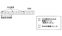
- FIG. 2 is a diagram illustrating an example of a radio resource (hereinafter referred to as a resource) for transmitting a discovery signal.
- a discovery resource for example, discovery subframe
- discovery signal interval discovery signal interval
- each user apparatus UE selects, for example, any one of the plurality of blocks.
- the discovery signal is transmitted, and the discovery signal is received in any block.
- the part other than the discovery period is used for communication via a normal base station eNB.
- synchronized discovery signal transmission / reception is assumed. This will be described with reference to FIG.
- Fig.3 (a) when each user apparatus UE1 and UE2 exist in network coverage (in a cell), user apparatus UE1 and UE2 synchronize with the base station eNB by the downlink signal from the base station eNB. As a result, the user apparatus UE is also synchronized.
- the discovery period (in this example, a subframe) to be recognized between the user apparatuses UE is aligned by synchronization between the user apparatuses UE, so that the discovery transmitted by the user apparatus UE1
- the user apparatus UE2 can appropriately receive the signal.
- discovery performance can be improved and energy consumption can be suppressed by detecting discovery signals in synchronization.
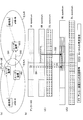
- a base station eNB-A and a base station eNB-B that are not synchronized exist, and a user apparatus UE1 that is synchronized with the base station eNB-A and a user apparatus UE2 that is synchronized with the base station eNB-B are D2D. Assume communication.
- the subframe 3 is defined as a discovery signal transmission / reception subframe (discovery subframe), as shown in FIG.
- a discovery signal is transmitted in subframe 3 of the cell.
- the time that the user apparatus UE1 recognizes as the subframe 3 is between the subframes 0 and 1 for the user apparatus UE2, and the subframe 3 is not. Therefore, at the time when the user apparatus UE1 recognizes that it is the subframe 3, the user apparatus UE2 does not expect to receive the discovery signal, and cannot receive the discovery signal transmitted from the user apparatus UE1. .
- the present invention has been made in view of the above points, and an object of the present invention is to provide a technique that enables transmission and reception of discovery signals for D2D communication between asynchronous user apparatuses in an inter-cell asynchronous environment. .
- a user equipment used in a wireless communication system comprising a base station forming a cell and receiving a discovery signal of device-to-device communication, An information receiving unit that receives a range of resources from which a discovery signal can be transmitted in a neighboring cell from a base station of a serving cell; A discovery signal receiving unit that receives a discovery signal at a time position synchronized with an adjacent cell in response to receiving a synchronization signal synchronized with an adjacent cell within a range of resources received by the information receiving unit;
- the user apparatus characterized by this is provided.
- a user apparatus is used in a radio communication system including a base station forming a cell and receives a discovery signal of apparatus-to-apparatus communication, A difference determining unit that determines a timing difference between the serving cell and the neighboring cell based on the downlink signal received from the base station of the serving cell and the downlink signal received from the base station of the neighboring cell; An information transmission unit for transmitting a timing difference determined by the difference determination unit to a base station of a serving cell; Based on the timing difference, obtain a range of resources in which the discovery signal can be transmitted in the neighboring cell, and synchronize with the neighboring cell in response to receiving a synchronization signal synchronized with the neighboring cell within the range of the resource. And a discovery signal receiving unit that receives the discovery signal at the time position.
- a user apparatus that is used in a radio communication system including a base station that forms a cell and transmits a discovery signal of apparatus-to-apparatus communication, An information receiver that receives a range of resources from which a discovery signal can be received in a neighboring cell from a base station of a serving cell; A discovery signal transmission unit that transmits a discovery signal at a time position synchronized with an adjacent cell in response to receiving a synchronization signal synchronized with an adjacent cell within the range of resources received by the information reception unit;
- the user apparatus characterized by this is provided.
- a user apparatus that is used in a radio communication system including a base station that forms a cell and transmits a discovery signal of apparatus-to-apparatus communication, A difference determining unit that determines a timing difference between the serving cell and the neighboring cell based on the downlink signal received from the base station of the serving cell and the downlink signal received from the base station of the neighboring cell; An information transmission unit for transmitting a timing difference determined by the difference determination unit to a base station of a serving cell; Based on the timing difference, obtain a range of resources in which the discovery signal can be received in the neighboring cell, and synchronize with the neighboring cell in response to receiving a synchronization signal synchronized with the neighboring cell within the range of the resource. And a discovery signal transmission unit that transmits a discovery signal at the time position.
- a base station used in a wireless communication system and communicating with a user device that transmits and receives a discovery signal of device-to-device communication
- a resource range determination unit that receives a discovery signal from a user apparatus residing in an adjacent cell and determines a resource range in which the discovery signal can be transmitted and received in the adjacent cell based on the discovery signal;
- a base station comprising: a resource range transmitter configured to transmit a resource range determined by the resource range determiner to a user apparatus residing in a cell of the base station.
- a base station used in a wireless communication system and communicating with a user device that transmits and receives a discovery signal of device-to-device communication, From the user equipment residing in the cell of the base station, the timing difference between the cell and the neighboring cell is received, and based on the timing difference, the resource range in which the discovery signal can be transmitted and received in the neighboring cell
- a base station comprising: a resource range transmitter configured to transmit a resource range determined by the resource range determiner to a user apparatus residing in a cell of the base station.
- FIG. 1 is an overall configuration example of a system according to an embodiment of the present invention. It is a figure which shows the outline
- FIG. 1 is an overall configuration example of a system according to an embodiment of the present invention. It is a figure which shows the outline
- FIG. 10 is a diagram showing a specific example of the first method in step 101. It is a figure which shows the specific example of the 2nd method in step 101.
- FIG. It is the procedure example 1 of the measurement and notification which the user apparatus UE of a cell edge performs in a 2nd method. It is the procedure example 2 of the measurement and notification which the user apparatus UE of a cell edge performs in a 2nd method. It is an example of a procedure of communication between base stations. It is a figure which shows the modification of a 2nd method. It is a figure which shows the specific example of the modification of a 2nd method.
- FIG. 5 is a diagram showing a specific example of the first method in step 102.
- FIG. 10 is a diagram showing a specific example of the second method in step 102.
- FIG. 10 is a diagram showing a specific example of the third method in step 102.
- It is a functional block diagram of the user apparatus UE in 1st Embodiment.
- It is a functional block diagram of the base station eNB in 1st Embodiment.
- It is another functional block diagram of the user apparatus UE in 1st Embodiment.
- It is a flowchart which shows the outline
- FIG. 5 is a diagram showing a specific example of the first method in step 201.
- FIG. 5 is a diagram showing a specific example of the first method in step 201.
- FIG. 10 is a diagram showing a specific example of the second method in step 201. It is a figure which shows the specific example of the modification of a 2nd method.
- FIG. 5 is a diagram showing a specific example of the first method in step 202. It is a figure which shows the specific example of the 2nd method of step 202.
- FIG. It is a function block diagram of the user apparatus UE in 2nd Embodiment. It is a function block diagram of the base station eNB in 2nd Embodiment. It is another functional block diagram of the user apparatus UE in 2nd Embodiment. It is another functional block diagram of the base station eNB in 2nd Embodiment.
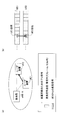
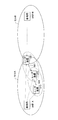
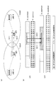
- FIG. 5 shows an example of the entire system configuration in the embodiment of the present invention (common to the first and second embodiments).
- the user apparatus UE in the present embodiment, in an environment where the base station eNB-A and the base station eNB exist (assuming that they are asynchronous), the user apparatus UE (example) in the cell A of the base station eNB-A : User apparatus UE1) and user apparatus UE (user apparatus UE2) in cell B of base station eNB-B perform discovery signal transmission / reception for D2D communication.
- the user apparatus UE1 in the cell A of the base station eNB-A is synchronized with the base station eNB-A
- the user apparatus UE2 in the cell B of the base station eNB-B is synchronized with the base station eNB-B.
- the base station eNB-A and the base station eNB-B are not synchronized, the user apparatus UE1 is not synchronized with the user apparatus UE2.
- the user apparatus UE2 grasps the time of the discovery period (discovery subframe) in the neighboring cell A (user apparatus UE1). In this period, an operation (listen) for receiving the discovery signal is performed.
- the user apparatus UE1 grasps the time of the discovery period (discovery subframe) in the neighboring cell (user apparatus UE2) and transmits a discovery signal in the period.
- the discovery period is “subframe”, but this is only an example.
- the discovery period may be a plurality of subframes or other periods.
- FIG. 8 is a flowchart showing an overview of the flow of processing executed by the user apparatus UE on the reception side of the discovery signal in the present embodiment.
- Step 101 The user apparatus UE determines a (rough) resource range (eg, time-frequency range, time range) in which discovery signals from neighboring cells can exist.
- a resource range eg, time-frequency range, time range
- the “resource range” in step 101 is mainly a time range in the specific example, but the resource range may be a time-frequency range.
- a signal received from the base station eNB (or user apparatus UE) in the own cell is used. That is, the base station eNB (or user apparatus UE) of the own cell determines a rough (approximate) resource range in which a discovery signal from an adjacent cell can appear, and notifies the user apparatus UE at its own timing.
- the base station eNB observes the discovery signal transmitted from the neighboring cell and detects the resource range of the discovery signal in the neighboring cell based on the observation. Then, the user apparatus UE is notified of the information.
- the user apparatus UE at the cell edge receives a downlink signal from the base station eNB of the adjacent cell, thereby detecting a subframe timing difference between the own cell and the adjacent cell, Information is notified to the base station eNB of the own cell. Then, the base station eNB notifies the subordinate user apparatus UE of the difference information. Thereby, the said user apparatus UE can grasp
- Step 102 In Step 101, the user apparatus UE notified of the range of resources from which the discovery signal can be transmitted from the adjacent cell is synchronized with the timing in the adjacent cell and transmitted from the user apparatus UE of the adjacent cell in the range. Receive (detect) the found signal.
- the user apparatus UE receives a synchronization signal from the neighboring cell.
- the user apparatus UE receives the synchronization signal transmitted from the base station eNB of the adjacent cell.
- the user apparatus UE receives a synchronization signal from the user apparatus UE (anchor UE) selected in the adjacent cell.
- the user apparatus UE receives a synchronization signal from the user apparatus UE that transmits a discovery signal in a neighboring cell. That is, the user apparatus UE in the adjacent cell transmits a discovery signal together with the synchronization signal.
- Step 101 The user apparatus UE grasps a resource range in which a discovery signal can be transmitted from a neighboring cell] ⁇ First Method in Step 101> First, the first method in step 101 will be described in detail. As described above, in the first method, the base station eNB observes the discovery signal transmitted from the neighboring cell, and based on the observation, the rough resource range of discovery signal transmission in the neighboring cell (eg, time-frequency) (Range, time range) is detected, and a signal including the information is notified to the subordinate user apparatus UE.
- the base station eNB observes the discovery signal transmitted from the neighboring cell, and based on the observation, the rough resource range of discovery signal transmission in the neighboring cell (eg, time-frequency) (Range, time range) is detected, and a signal including the information is notified to the subordinate user apparatus UE.
- the base station eNB observes the discovery signal transmitted from the neighboring cell, and based on the observation, the rough resource range of discovery signal transmission in the neighboring cell (e
- the signal that the base station eNB notifies the user equipment UE under its control includes, for example, information on the absolute time-frequency range, the absolute time range, or the difference from the discovery resource position in the own cell.
- the method for notifying the signal is not limited, but can be notified by broadcast signaling such as broadcast information, RRC signaling, (E) PDCCH signaling, or the like. A combination of these may also be used.
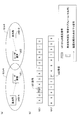
- FIGS. 9 (a) and 9 (b) A specific example of the first method will be described with reference to FIGS. 9 (a) and 9 (b).
- the user apparatus UE1 and the user apparatus UE3 are in the cell A, and the user apparatus UE2 is in the cell B.
- subframe 3 is allocated as a subframe for transmitting and receiving a discovery signal in each cell.
- the resource range will be described with particular attention to the time range, but the base station eNB also grasps the frequency range (band range) of the discovery resource of the neighboring cell based on the discovery signal received. Then, the frequency difference (or adjacent cell use frequency) may be notified together with the time difference.
- the position of the user apparatus UE1 is not only the cell edge of the cell A but also the cell edge of the cell B.
- the user apparatus UE1 transmits a discovery signal in the subframe 3, and the discovery signal is received by the user apparatus UE3 and also received by the base station eNB-B of the cell B (step 11).
- the base station eNB-B that has received the discovery signal determines that the discovery signal of the neighboring cell A is transmitted in subframes 0 and 1 at the timing of the own station, and notifies the user apparatus UE2 in the own station to the neighboring device in the neighboring cell.
- the discovery subframe is notified that it is in the range of subframes 0 and 1 in its own station (step 12).
- the user apparatus UE2 that has received this notification decides to monitor the discovery signal from the neighboring cell A in subframes 0 and 1. As will be described later, during this monitoring period, a synchronization signal is received and a discovery signal is received (detected).
- the user apparatus UE (for example, the above-described user apparatus UE2) that has received the above notification from the base station eNB of the local station may always monitor the discovery signal from the adjacent cell, or when a predetermined condition is satisfied It is also possible to monitor only.
- the user apparatus UE determines to monitor the discovery signal from the neighboring cell based on the reference signals from the serving base station eNB and the neighboring base station eNB. For example, monitoring the discovery signal from the neighboring cell when the strength of the reference signal from the neighboring base station eNB is larger than a predetermined threshold and the strength of the reference signal from the serving base station eNB is smaller than the predetermined threshold. decide.
- the said threshold value can be updated suitably with the downlink signal from the serving base station eNB, for example.
- the downlink signal is notified by broadcast signaling, (e) PDCCH, RRC signaling, or the like.
- the serving base station eNB or the neighboring base station eNB may directly instruct the user apparatus UE to monitor the discovery signal of the neighboring cell.
- the above method for determining whether or not the user apparatus UE monitors the discovery signal from the neighboring cell is the same in other method examples.
- the second method in step 101 will be described in detail.
- the user equipment UE at the cell edge receives a downlink signal from the base station eNB of the adjacent cell, thereby detecting the difference in subframe timing between the own cell and the adjacent cell. And the information of the difference is notified to the base station eNB of the own cell. Then, the base station eNB notifies the subordinate user apparatus UE of the difference information.
- the base station eNB notifies the adjacent base station eNB of the timing difference using a backhaul line (eg, X2 interface). And the adjacent base station eNB which received the notification notifies the subordinate user apparatus UE of the range which should monitor the discovery signal from an adjacent cell.
- the information to be notified may be absolute information or may be a difference between the discovery resource position and the own station.
- the information is transmitted by, for example, broadcast signaling, RRC signaling, (e) PDDCH signaling, or a combination thereof.
- the user apparatus UE at the cell edge may measure the downlink signal from the base station eNB in the adjacent cell and notify the difference, for example, in response to signaling from the base station eNB in the adjacent cell.
- the measurement and notification may be triggered by an event that satisfies a certain condition.
- the event for example, the strength of a discovery signal from an adjacent cell is larger than a predetermined threshold.
- the user apparatus UE that has received the notification of the resource range of the discovery signal from the neighboring cell receives the discovery signal from the neighboring cell by itself or by an instruction from the base station eNB in the same manner as in the first method. Decide whether to monitor.
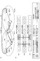
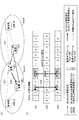
- the user apparatus UE1 and the user apparatus UE3 are in the cell A, and the user apparatus UE2 is in the cell B.
- subframe 3 is assigned as a subframe for transmitting and receiving a discovery signal in each cell.
- the resource range of the discovery signal of the adjacent cell will be described with particular attention to the time range.
- the user apparatus UE is based on downlink signals from the serving base station eNB and the neighboring base station eNB.
- the frequency range (band range) of the discovery resource of the neighboring cell may be grasped, and the neighboring cell use frequency or the frequency difference may be notified to the serving base station eNB together with the time difference.
- the position of the user apparatus UE1 is the cell edge of the cell A and the cell edge of the cell B.
- the user apparatus UE1 receives the downlink signal from the base station eNB-A and also receives the downlink signal from the base station eNB-B (step 21).
- the user apparatus UE1 determines the timing difference between the base station eNB-A and the base station eNB-B (in this example, based on the downlink signal from the base station eNB-A and the downlink signal from the base station eNB-B). , Approximately 2.5 subframes).
- the user apparatus UE1 notifies the base station eNB-A of information indicating that the cell A is advanced by about 2.5 subframes than the cell B (step 22).
- the base station eNB-A that has received the notification notifies the base station eNB-B of the timing difference information using the backhaul line (step 23). Also, the base station eNB-A, for the subordinate user apparatus UE3, as a resource range of the discovery subframe of the adjacent cell B, a subframe corresponding to a time position delayed by 2.5 subframes from the subframe 3 5 and 6 are notified (step 24). By performing notification using the backhaul line in this way, the base station eNB-B can efficiently acquire timing information of neighboring cells.
- the base station eNB-B transmits, to the subordinate user apparatus UE2, the subframe corresponding to the time position advanced by 2.5 subframes from the subframe 3 as the resource range of the discovery subframe of the adjacent cell A 0 and 1 are notified (step 25).
- the user apparatuses UE1 and 3 of the cell A are the subframes 5 and 6 including the time position of the discovery subframe of the adjacent cell B from the adjacent cell B (user apparatus UE2). Monitor discovery signals. Further, the user apparatus UE2 in the cell B monitors the discovery signal from the adjacent cell A (user apparatuses UE1 and UE3) in subframes 0 and 1 including the time position of the discovery subframe in the adjacent cell A.
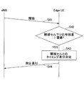
- Example 1 The procedure of Example 1 will be described with reference to FIG.
- measurement and notification are performed using a signaling from a base station eNB that is present as a trigger. That is, as shown in FIG. 11, the base station eNB transmits a measurement request to the user equipment UE at the cell edge (step 31). Based on the measurement request, the user apparatus UE measures a timing difference between the adjacent cell and the serving cell (step 32), and transmits the timing difference to the base station eNB as a measurement report (measurement report) ( Step 33).
- Example 2 A procedure example of Example 2 will be described with reference to FIG. In Example 2, measurement and notification are performed in response to a predetermined event.
- the base station eNB transmits a threshold value to the user equipment UE at the cell edge (step 41).
- the user apparatus UE compares the downlink signal strength of the neighboring cell with a threshold (step 42), and measures the timing difference between the neighboring cell and the serving cell when the downlink signal strength of the neighboring cell is larger than the threshold. Then, the timing difference is transmitted as a measurement notification to the base station eNB (step 44).
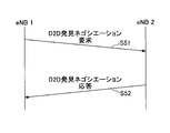
- the base station eNB1 transmits a D2D discovery negotiation request to the base station eNB2 (step 51).
- the base station eNB2 that has received the D2D discovery negotiation request transmits a D2D discovery negotiation response to the base station eNB1 (step 52).
- the D2D discovery negotiation response includes information on the timing difference received from the subordinate user apparatus UE. Also, the timing difference information received from the subordinate user apparatus UE may be included in the D2D discovery negotiation request.
- the user equipment UE at the cell edge may transmit (broadcast) the timing difference estimation result to the surrounding user equipment UE by the discovery signal. This can be performed, for example, when the user apparatus UE is in the RRC idle state and cannot communicate with the base station eNB or requires a processing amount for communication.
- the discovery signal transmitted by the user equipment UE at the cell edge includes timing difference information.
- a 4-bit message segment indicates the number of subframes of timing difference (offset).
- 0011 indicates a timing difference for three subframes.
- a 2-bit message segment indicates the number of subframes (period length) for which a discovery signal from a neighboring cell should be monitored. As an example, 10 indicates that discovery signals from neighboring cells are monitored for two subframes.
- the user apparatus UE when a neighboring user apparatus UE receives a discovery signal including timing difference information, the user apparatus UE includes the timing difference information in its own discovery signal and transmits the discovery signal.
- the base station eNB may transmit a threshold value for determining whether or not the user apparatus UE transmits timing difference information with a discovery signal to neighboring user apparatuses UE.
- the user apparatus UE sends a discovery signal including timing difference information to the neighboring user apparatuses UE only when the strength of the downlink signal from the base station eNB is smaller than the threshold (eg, when present at the cell edge). Send.
- the threshold eg, when present at the cell edge.
- the user apparatus UE2 receives the timing difference information transmitted from the user apparatus UE1 in the discovery signal.
- the user apparatus UE2 includes the information in the discovery signal and transfers it to the user apparatus UE3 (Step 62).
- the surrounding user apparatus UE determines whether to monitor the discovery signal from the neighboring cell based on its own determination or an instruction from the base station eNB.
- FIG. 15A in this example, the user apparatus UE1 and the user apparatus UE3 are in the cell A, and the user apparatus UE2 is in the cell B.
- subframe 3 is assigned as a subframe for transmitting and receiving a discovery signal in each cell.
- the position of the user apparatus UE1 is not only the cell edge of the cell A but also the cell edge of the cell B.
- the user apparatus UE1 receives the downlink signal from the base station eNB-A and also receives the downlink signal from the base station eNB-B (step 71).
- the user apparatus UE1 determines the timing difference between the base station eNB-A and the base station eNB-B (in this example, based on the downlink signal from the base station eNB-A and the downlink signal from the base station eNB-B). , Approximately 2.5 subframes).
- the user apparatus UE1 transmits a discovery signal including information indicating that the cell A is advanced by about 2.5 subframes than the cell B (step 72).
- the discovery signal including the timing difference information transmitted from the user apparatus UE1 is received by the user apparatus UE3 in the same cell. Then, the user apparatus UE3 learns that the discovery subframe in the adjacent cell B is in the range of subframes 5 and 6. In this way, the user apparatuses UE1 and UE3 can monitor the discovery signal from the neighboring cell B in the subframes 5 and 6.
- the user apparatus UE can efficiently receive the discovery signal from the adjacent cell even in an asynchronous environment.
- Step 102 The user apparatus UE synchronizes with a neighboring cell
- the user apparatus UE monitors the discovery signal from the user apparatus UE in the neighboring cell within the monitoring resource range of the neighboring cell discovery signal notified in step 101.
- a synchronization signal is received, synchronized with an adjacent cell, and a discovery signal is received (detected) at an accurate timing.
- the first to third methods in step 102 will be described in detail.
- the synchronization signal in this example is a signal having a predetermined pattern, for example, and when the user apparatus UE detects that the synchronization signal (predetermined pattern) has been received, the sub-discovery signal is detected after a predetermined time (T described later).
- T a predetermined time
- an operation of decoding a discovery signal can be performed by determining that the frame is to be generated.
- the time T or information of discovery resources may be included in the synchronization signal.
- the user apparatus UE receives a downlink signal (synchronization signal) of the base station eNB of the adjacent cell, thereby synchronizing with the adjacent cell and detecting a discovery signal from the adjacent cell. That is, in the first method, a synchronization signal for synchronization in the user apparatus UE is transmitted from the adjacent base station eNB.
- a downlink signal synchronization signal
- Time T is predetermined as the time between the discovery subframe and the synchronization signal, and the user apparatus UE that has received the synchronization signal from the neighboring base station eNB starts the discovery subframe in the neighboring cell after time T.
- the discovery signal can be accurately received (detected).
- the synchronization signal transmitted from the adjacent base station eNB may be an existing downlink signal such as PSS / SSS, or may be a signal newly defined for D2D synchronization of the adjacent cell.
- the base station eNB-A transmits a synchronization signal using a downlink band (DL spectrum) (step 81).
- the user apparatus UE2 existing in the cell B synchronizes with the adjacent cell A by receiving the synchronization signal from the base station eNB-A. That is, the user apparatus UE2 synchronizes with the base station eNB-A and the user apparatus UE1.
- This synchronization signal is received by, for example, asynchronous detection (Non-coherent detection).
- the user apparatus UE2 Upon receiving the synchronization signal, the user apparatus UE2 determines the resource position of the discovery signal transmitted from the user apparatus UE1 in the adjacent cell (it is a time-frequency position, but in this example, pays particular attention to the time position).
- the discovery signal from the user apparatus UE1 can be detected (step 82).
- coherent detection is possible.
- the synchronization signal may exist in a discovery subframe in a cell (intra-cell) that transmits the synchronization signal, or may not exist in a discovery subframe.
- the example shown in FIG. 16 is an example when the synchronization signal is not in the discovery subframe.
- a synchronization signal is transmitted from a specific user apparatus UE (referred to as an anchor UE) to a user apparatus UE in an adjacent cell, the user apparatus UE synchronizes with the adjacent cell, and a discovery signal from the adjacent cell. Is detected.
- the anchor UE is synchronized with the base station eNB of the cell. Further, the anchor UE may be a user apparatus UE selected by the base station eNB, or may be a predetermined user apparatus UE arranged in a distributed manner.
- the time T is determined in advance as the time between the discovery subframe and the synchronization signal, and the user apparatus UE that has received the synchronization signal from the anchor UE performs discovery in the neighboring cell after the time T. It is possible to grasp that the subframe starts, and to accurately receive the discovery signal.
- the synchronization signal transmitted from the anchor UE may be an existing signal such as PSS / SSS, or may be a new signal for D2D synchronization of an adjacent cell. Further, the synchronization signal is scheduled for the anchor UE so as not to interfere with normal cellular communication.
- the anchor UE located in the cell A transmits a synchronization signal using the uplink band (UL spectrum) (step 91).
- the user apparatus UE2 existing in the adjacent cell synchronizes with the adjacent cell A by receiving the synchronization signal from the anchor UE, that is, synchronizes with the anchor UE and the user apparatus UE1.
- the user apparatus UE2 can grasp the resource of the discovery signal transmitted from the user apparatus UE1 in the adjacent cell (in this example, pay attention to the time position) and detect the discovery signal from the user apparatus UE1. (Step 92).
- the synchronization signal may exist in a discovery subframe in a cell (intra-cell) that transmits the synchronization signal, or may not exist in a discovery subframe.
- the example shown in FIG. 17 is an example when the synchronization signal is not in the discovery subframe.
- the user apparatus UE transmits a synchronization signal together with the discovery signal.
- the user apparatus UE of the adjacent cell that receives these signals first detects a synchronization signal and then detects a discovery signal.
- the synchronization signal transmitted together with the discovery signal from the user apparatus UE may be an existing signal such as PSS / SSS or a new signal for D2D synchronization of the neighboring cell. Further, a plurality of user apparatuses UE may transmit the same synchronization signal, or may transmit different synchronization signals.
- the different synchronization signals are, for example, that the contents (patterns) are different between the synchronization signals.
- a plurality of user apparatuses UE may transmit synchronization signals using the same time-frequency resource, or may transmit synchronization signals using different time-frequency resources (which do not interfere with each other and are orthogonal).
- the user apparatus UE1 located in the cell A transmits a synchronization signal together with a discovery signal by using an uplink band (UL spectrum) (step 311, 312).
- the user apparatus UE2 existing in the cell B receives the synchronization signal from the user apparatus UE1, thereby synchronizing with the user apparatus UE1.
- the discovery signal transmitted from user apparatus UE1 is detected (step 312).
- the synchronization signal may exist in a discovery subframe in a cell (intra-cell) that transmits the synchronization signal, or may not exist in a discovery subframe.
- the example shown in FIG. 18 is an example when the synchronization signal is in the discovery subframe.
- FIG. 19 shows a functional configuration diagram of the user apparatus UE in the present embodiment.
- the example shown in FIG. 19 is an example of an apparatus that performs the operation of the first method in Step 101.
- Step 102 can be handled by any method.
- FIG. 19 particularly shows main functions related to the present embodiment in the user apparatus UE.
- the user apparatus UE may further include a function necessary for operating as a UE compliant with LTE (including LTE-Advanced).
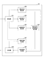
- the user apparatus UE includes a reception unit 101, a discovery signal detection unit 102, a control signal detection unit 103, a discovery signal monitoring range determination unit 104, a synchronization signal detection unit 105, a discovery signal generation unit 106, and a synchronization signal.
- a generation unit 107 and a transmission unit 108 are provided.
- the receiving unit 101 receives a discovery signal, a synchronization signal, a control signal from the base station eNB, and the like.
- the discovery signal detection unit 102 performs monitoring (reception signal demodulation, etc.) within the resource range determined by the discovery signal monitoring range determination unit 104, and when the synchronization signal is detected by the synchronization signal detection unit 105 within the resource range, Based on the synchronization signal, the detection signal is detected (decoded) at an accurate timing (at a time position synchronized with an adjacent cell).
- the control signal detection unit 103 demodulates and decodes the control signal received from the base station eNB, acquires the resource range (discovery subframe range, etc.) in the neighboring cell, passes it to the discovery signal monitoring range determination unit 104, The monitoring range determination unit 104 determines the resource range as the discovery signal monitoring range.
- the discovery signal generation unit 106 generates a discovery signal and transmits it from the transmission unit 108. Also, the synchronization signal generation unit 107 generates a synchronization signal when it becomes an anchor UE, or when it transmits a synchronization signal together with a discovery signal.
- a user apparatus UE is used in a wireless communication system including a base station forming a cell and receives a discovery signal of apparatus-to-device communication, and is detected in a neighboring cell from a base station of a serving cell
- An information receiving unit that receives a range of resources to which a signal can be transmitted, and synchronized with an adjacent cell in response to receiving a synchronization signal synchronized with the adjacent cell within the range of resources received by the information receiving unit
- a discovery signal receiving unit that receives the discovery signal at a time position.
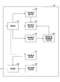
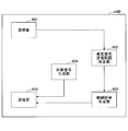
- FIG. 20 shows a functional configuration diagram of the base station eNB in the present embodiment.
- the example shown in FIG. 20 is an example in which the operation of the first method in step 101 is executed.
- Step 102 can be handled by any method.
- FIG. 20 particularly shows main functions related to the present embodiment in the base station eNB.
- the base station eNB may further include a function necessary for operating as an eNB compliant with LTE (including LTE-Advanced).
- the base station eNB includes a reception unit 201, a discovery signal monitoring range determination unit 202, a control signal generation unit 203, a synchronization signal generation unit 204, and a transmission unit 205.
- the reception unit 201 receives a discovery signal from the user apparatus UE in the adjacent cell, and passes information on the resource of the discovery signal to the discovery signal monitoring range determination unit 202.
- the discovery signal monitoring range determination unit 202 is a resource range in which the user apparatus UE of its own cell monitors a discovery signal from an adjacent cell based on the information on the resource (range of resources in which the discovery signal can be transmitted and received in the adjacent cell).
- the resource range is passed to the control signal generation unit 203.
- the control signal generation unit 203 generates a control signal including the resource range, and transmits the control signal from the transmission unit 205 to the user apparatus UE located in the own cell.
- the synchronization signal generation unit 204 generates a synchronization signal and transmits it from the transmission unit 205.
- a base station eNB is a base station that is used in a wireless communication system and communicates with a user apparatus that transmits and receives a discovery signal for device-to-device communication, and receives a discovery signal from a user device located in a neighboring cell, Based on the discovery signal, a resource range determination unit that determines a range of resources in which a discovery signal can be transmitted and received in an adjacent cell, and a range of resources determined by the resource range determination unit is located in the cell of the base station And a resource range transmission unit for transmitting to a user apparatus.
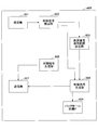
- FIG. 21 shows another functional configuration diagram of the user apparatus UE in the present embodiment.
- the example shown in FIG. 21 corresponds to the second method of step 101.
- Step 102 can be handled by any method.
- FIG. 21 particularly shows functions related to the present embodiment in the user apparatus UE.
- the user apparatus UE may further include a function necessary for operating as a UE compliant with LTE (including LTE-Advanced).
- the user apparatus UE includes a reception unit 301, a discovery signal detection unit 302, a difference determination unit 303, a synchronization signal detection unit 304, a control signal generation unit 305, a discovery signal generation unit 306, and a synchronization signal generation unit 307.
- the transmission unit 308 is provided.
- the receiving unit 301 receives a discovery signal, a synchronization signal, information from the base station eNB, and the like.
- the discovery signal detection unit 302 determines a resource range in which the discovery signal can be transmitted / received in the neighboring cell based on the resource difference from the neighboring cell determined by the difference determination unit 303, and monitors (received signal demodulation, etc.) in the resource range.
- the synchronization signal is detected by the synchronization signal detection unit 304, the detection signal is detected (decoded) at an accurate timing (time position synchronized with the adjacent cell) based on the synchronization signal.
- the difference determination unit 303 determines a resource difference (eg, timing difference) based on downlink signals received from the serving base station eNB and the adjacent base station eNB, and passes the information to the control signal generation unit 305. The information is also passed to the discovery signal detection unit 302. In addition, the discovery signal detection part 302 can also perform discovery signal monitoring using the resource range information contained in the control signal received from the base station eNB similarly to the user apparatus UE shown in FIG.
- a resource difference eg, timing difference
- the control signal generation unit 305 generates a control signal including a resource difference and transmits the control signal from the transmission unit 308 to the base station eNB.
- the discovery signal generator 306 generates a discovery signal and transmits it from the transmitter 108. In the case of the modification, the discovery signal generation unit 306 generates and transmits a discovery signal including a resource difference.
- the synchronization signal generation unit 107 generates a synchronization signal when it becomes an anchor UE or when the synchronization signal is transmitted together with the discovery signal.
- a user apparatus UE is used in a radio communication system including a base station that forms a cell, and is a user apparatus that receives a discovery signal of apparatus-to-apparatus communication, a downlink signal received from a base station of a serving cell, And a difference determination unit that determines a timing difference between the serving cell and the adjacent cell based on a downlink signal received from the base station of the adjacent cell, and a timing difference determined by the difference determination unit.
- a discovery signal receiving unit configured to receive a discovery signal at a time position synchronized with an adjacent cell in response to reception of the signal, and configured as a user apparatus. It may be.
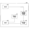
- FIG. 22 shows another functional configuration diagram of the base station eNB in the present embodiment.
- the example shown in FIG. 22 corresponds to the second method in step 101.
- Step 102 can be handled by any method.
- FIG. 22 particularly shows functions related to the present embodiment in the base station eNB.
- the base station eNB may further include a function necessary for operating as an eNB compliant with LTE (including LTE-Advanced).
- the base station eNB includes a reception unit 401, a control signal detection unit 402, a discovery signal monitoring range determination unit 403, a control signal generation unit 404, a synchronization signal generation unit 405, a backhaul line IF 406, and a transmission unit 407. Is provided.
- the receiving unit 401 receives a control signal including a resource difference from the user apparatus UE in the own cell.
- the control signal detection unit 402 acquires a resource difference from the control signal and passes the resource difference to the discovery signal monitoring range determination unit 403.
- the discovery signal monitoring range determination unit 403 is a resource range in which the user apparatus UE of its own cell monitors a discovery signal from the adjacent cell (range of resources in which the discovery signal can be transmitted and received in the adjacent cell). ) And pass the resource range to the control signal generation unit 404.
- the control signal generation unit 404 generates a control signal including the resource range, and transmits the control signal from the transmission unit 407 to the user apparatus UE located in the own cell.
- control signal generation unit 404 receives resource difference information from the control signal detection unit 402 and transmits the information to the adjacent base station eNB through the backhaul line IF 406.
- the backhaul line IF 406 also has a function of receiving the resource difference received from the adjacent base station eNB and passing it to the discovery signal monitoring range determination unit 403.
- the discovery signal monitoring range determination unit 403 can also determine a resource range for monitoring discovery signals from neighboring cells based on the resource difference.
- the synchronization signal generation unit 405 generates a synchronization signal and transmits it from the transmission unit 407.
- a base station eNB is a base station that is used in a wireless communication system and communicates with a user apparatus that transmits and receives a discovery signal of apparatus-to-apparatus communication, and the user apparatus residing in the cell of the base station from the cell
- a resource range determination unit that receives a timing difference between a cell and a neighboring cell and determines a resource range in which a discovery signal can be transmitted and received in the neighboring cell based on the timing difference, and is determined by the resource range determination unit
- the resource range may be configured to include a resource range transmission unit that transmits the resource range to a user apparatus residing in the cell of the base station.
- FIG. 23 is a flowchart showing an outline of the flow of processing executed by the user apparatus UE on the side of transmitting a discovery signal in the present embodiment.
- Step 201) The user apparatus UE determines a (rough) resource range (eg, time-frequency range, time range) in which discovery signals from neighboring cells can exist. That is, the resource range in which the discovery signal can be detected in the adjacent cell is determined.
- a resource range eg, time-frequency range, time range
- the resource range may be a time-frequency range.
- the determination method here is the same as in the first embodiment, and there are a first method and a second method.
- the base station eNB observes the discovery signal transmitted from the neighboring cell, detects the resource range of discovery signal reception in the neighboring cell based on the observation, and notifies the user apparatus UE under the information of the resource range. To do.
- the user apparatus UE at the cell edge receives a downlink signal from the base station eNB of the adjacent cell, thereby detecting a subframe timing difference between the own cell and the adjacent cell, Information is notified to the base station eNB of the own cell. Then, the base station eNB notifies the subordinate user apparatus UE of the difference information. Thereby, the said user apparatus UE can grasp
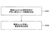
- Step 202) the user apparatus UE notified of the range of resources from which the discovery signal from the neighboring cell can be detected is synchronized with the timing in the neighboring cell during the period of the range, and the discovery subframe in the neighboring cell Then, send a discovery signal.
- the user apparatus UE receives a synchronization signal from the neighboring cell.
- the user apparatus UE receives the synchronization signal transmitted from the base station eNB of the adjacent cell.
- the user apparatus UE receives a synchronization signal from the user apparatus UE (anchor UE) selected in the adjacent cell.
- Step 201 The user apparatus UE grasps a resource range in which a discovery signal can be detected in a neighboring cell] ⁇ First Method in Step 201> First, the first method in step 201 will be described in detail. As described above, in the first method, the base station eNB observes a discovery signal transmitted from an adjacent cell, and based on the observation, a rough resource range of discovery signal transmission / reception in the neighboring cell (eg, time-frequency) (Range, time range) is detected, and a signal including the information is notified to the subordinate user apparatus UE.
- a rough resource range of discovery signal transmission / reception in the neighboring cell eg, time-frequency
- Range time range
- the signal that the base station eNB notifies the user equipment UE under its control includes, for example, information on the absolute time-frequency range, the absolute time range, or the difference from the discovery resource position in the own cell.
- the method for notifying the signal is not limited, but can be notified by broadcast signaling such as broadcast information, RRC signaling, (E) PDCCH signaling, or the like. A combination of these may also be used.
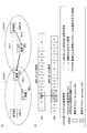
- the user apparatus UE1 and the user apparatus UE3 are in the cell A, and the user apparatus UE2 is in the cell B.
- subframe 3 is allocated as a subframe for transmitting and receiving a discovery signal in each cell.
- the resource range will be described with particular attention to the time range, but the base station eNB also grasps the frequency range (band range) of the discovery resource of the neighboring cell based on the discovery signal received. Then, the frequency difference (or adjacent cell use frequency) may be notified together with the time difference.
- the position of the user apparatus UE1 is not only the cell edge of the cell A but also the cell edge of the cell B.
- the user apparatus UE1 transmits a discovery signal in the subframe 3, and the discovery signal is received by the user apparatus UE3 and also received by the base station eNB-B of the cell B (step 211).
- the base station eNB-B that has received the discovery signal determines that the discovery period of the adjacent cell A corresponds to subframes 0 and 1 in the timing of the local station, and notifies the user apparatus UE2 in the local station to the discovery substation in the adjacent cell. It is notified that the frame is in the range of subframes 0 and 1 at its own station (step 212).
- the user apparatus UE2 that has received this notification decides to transmit a discovery signal to the user apparatus UE1 in the adjacent cell A in the range of subframes 0 and 1. Thereafter, as will be described later, the discovery signal is transmitted in synchronization with the detection timing in the adjacent cell by the synchronization signal.
- the user apparatus UE (for example, the above-described user apparatus UE2) that has received the above notification from the base station eNB of the local station may always transmit a discovery signal at the timing of the adjacent cell, or when a predetermined condition is satisfied It is good also as transmitting only to.
- the user apparatus UE determines to transmit a discovery signal at the timing of the neighboring cell based on the reference signals from the serving base station eNB and the neighboring base station eNB.
- the discovery signal is transmitted at the timing of the neighboring cell when the strength of the reference signal from the neighboring base station eNB is larger than a predetermined threshold value and the strength of the reference signal from the serving base station eNB is smaller than the predetermined threshold value.
- the said threshold value can be updated suitably with the downlink signal from the serving base station eNB, for example.
- the downlink signal is notified by broadcast signaling, (e) PDCCH, RRC signaling, or the like.
- the serving base station eNB or the adjacent base station eNB may instruct the user apparatus UE to transmit a discovery signal at the timing of the adjacent cell.
- the above method for determining whether or not the user apparatus UE transmits a discovery signal at the timing of the neighboring cell is the same in other examples.
- the second method in step 201 will be described in detail.
- the user equipment UE at the cell edge receives the downlink signal from the base station eNB or the like of the adjacent cell, and thereby the subframe timing difference between the own cell and the adjacent cell is reduced. And the difference information is notified to the base station eNB of the own cell. Then, the base station eNB notifies the subordinate user apparatus UE of the difference information.
- the base station eNB may notify the adjacent base station eNB of the timing difference using a backhaul line (eg, X2 interface). And the adjacent base station eNB which received notification notifies the resource range which should transmit a discovery signal to a neighboring cell with respect to the subordinate user apparatus UE.
- the information to be notified may be absolute information or may be a difference between the discovery resource position and the own station.
- the information is transmitted by, for example, broadcast signaling, RRC signaling, (e) PDDCH signaling, or a combination thereof.
- the user apparatus UE at the cell edge may measure the downlink signal from the base station eNB in the adjacent cell and notify the difference, for example, in response to signaling from the base station eNB in the adjacent cell.
- the measurement and notification may be triggered by an event that satisfies a certain condition.
- the event for example, the strength of a discovery signal from an adjacent cell is larger than a predetermined threshold.
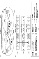
- the user apparatus UE1 and the user apparatus UE3 are in the cell A, and the user apparatus UE2 is in the cell B.
- subframe 3 is assigned as a subframe for transmitting and receiving a discovery signal in each cell.
- the resource range of the discovery signal of the adjacent cell will be described with particular attention to the time range.
- the user apparatus UE is based on downlink signals from the serving base station eNB and the neighboring base station eNB.
- the frequency range (band range) of the discovery resource of the neighboring cell may be grasped, and the neighboring cell use frequency or the frequency difference may be notified to the serving base station eNB together with the time difference.
- the position of the user apparatus UE1 is the cell edge of the cell A and the cell edge of the cell B.
- the user apparatus UE1 receives the downlink signal from the base station eNB-A and also receives the downlink signal from the base station eNB-B (step 221).
- the user apparatus UE1 determines the timing difference between the base station eNB-A and the base station eNB-B (in this example, based on the downlink signal from the base station eNB-A and the downlink signal from the base station eNB-B). , Approximately 2.5 subframes).
- the user apparatus UE1 notifies the base station eNB-A of information indicating that the cell A has advanced about 2.5 subframes than the cell B (step 222).
- the base station eNB-A that has received the notification notifies the base station eNB-B of the timing difference information using the backhaul line (step 223). Also, the base station eNB-A, for the subordinate user apparatus UE3, as a resource range of the discovery subframe of the adjacent cell B, a subframe corresponding to a time position delayed by 2.5 subframes from the subframe 3 5 and 6 are notified (step 224).
- the base station eNB-B transmits, to the subordinate user apparatus UE2, the subframe corresponding to the time position advanced by 2.5 subframes from the subframe 3 as the resource range of the discovery subframe of the adjacent cell A 0 and 1 are notified (step 225).
- user apparatus UE1,3 of the cell A is the adjacent cell B (user apparatus UE2) in the range of the subframes 5 and 6 including the time position of the discovery subframe of the adjacent cell B.
- the user apparatus UE2 of the cell B determines to transmit a discovery signal to the adjacent cell A (user apparatuses UE1 and UE3) in subframes 0 and 1 including the time position of the discovery subframe of the adjacent cell A.
- the measurement and notification procedure example performed by the cell edge user apparatus UE in the second method is the same as in the first embodiment, and is as described with reference to FIGS. .
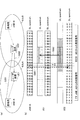
- the user equipment UE at the cell edge may transmit (broadcast) the timing difference estimation result to the surrounding user equipment UE by the discovery signal. This can be performed, for example, when the user apparatus UE is in the RRC idle state and cannot communicate with the base station eNB or requires a processing amount for communication.
- the discovery signal transmitted by the user equipment UE at the cell edge includes timing difference information.
- a 4-bit message segment indicates the number of subframes of timing difference (offset).
- 0011 indicates a timing difference for three subframes.
- a 2-bit message segment indicates the number of subframes (period length) for transmitting a discovery signal to a neighboring cell.
- 10 indicates that a discovery signal can be transmitted to a neighboring cell for a period of two subframes.
- the user apparatus UE when a neighboring user apparatus UE receives a discovery signal including timing difference information, the user apparatus UE includes the timing difference information in its own discovery signal and transmits the discovery signal.
- the base station eNB may transmit a threshold value for determining whether or not the user apparatus UE transmits timing difference information with a discovery signal to neighboring user apparatuses UE.
- the user apparatus UE finds that the user apparatus UE in the vicinity includes the timing difference information only when the strength of the downlink signal from the base station eNB is smaller than the threshold (for example, when it exists at the cell edge). Send a signal.
- the user apparatus UE1 and the user apparatus UE3 are in the cell A, and the user apparatus UE2 is in the cell B.
- subframe 3 is assigned as a subframe for transmitting and receiving a discovery signal in each cell.
- the position of the user apparatus UE1 is not only the cell edge of the cell A but also the cell edge of the cell B.
- the user apparatus UE1 receives a downlink signal from the base station eNB-A and also receives a downlink signal from the base station eNB-B (step 271).
- the user apparatus UE1 determines the timing difference between the base station eNB-A and the base station eNB-B (in this example, based on the downlink signal from the base station eNB-A and the downlink signal from the base station eNB-B). , Approximately 2.5 subframes).
- the user apparatus UE1 transmits a discovery signal including information indicating that the cell A is advanced by about 2.5 subframes than the cell B (step 272).
- the discovery signal including the timing difference information transmitted from the user apparatus UE1 is received by the user apparatus UE3 in the same cell. Then, the user apparatus UE3 learns that the discovery subframe in the adjacent cell B is in the range of subframes 5 and 6. In this way, the user apparatuses UE1 and UE3 can transmit a discovery signal to the neighboring cell B in the subframes 5 and 6.
- the user apparatus UE can efficiently detect in the adjacent cell even in an asynchronous environment.
- a discovery signal can be transmitted.
- Step 202 The user apparatus UE synchronizes with a neighboring cell
- the user apparatus UE receives the synchronization signal within the resource range of the neighboring cell discovery signal notified in step 201, synchronizes with the neighboring cell, and transmits the discovery signal to the user apparatus UE in the neighboring cell.
- the first and second methods in step 202 will be described in detail.
- the synchronization signal in this example is a signal having a predetermined pattern, for example, and when the user apparatus UE detects that the synchronization signal (predetermined pattern) has been received, the sub-discovery signal is detected after a predetermined time (T described later). It is determined that it is a frame, and a discovery signal is transmitted after a predetermined time. Further, the time T or information of discovery resources (time-frequency resources) may be included in the synchronization signal.
- the user apparatus UE receives a downlink signal (synchronization signal) of the base station eNB of the adjacent cell, thereby synchronizing with the adjacent cell and transmitting a discovery signal to the adjacent cell.
- a downlink signal synchronization signal
- a synchronization signal for synchronization in the user apparatus UE is transmitted from the adjacent base station eNB.
- Time T is predetermined as the time between the discovery subframe and the synchronization signal, and the user apparatus UE that has received the synchronization signal from the neighboring base station eNB starts the discovery subframe in the neighboring cell after time T. And the discovery signal can be transmitted at an accurate timing.
- the synchronization signal transmitted from the adjacent base station eNB may be an existing downlink signal such as PSS / SSS, or may be a signal newly defined for D2D synchronization of the adjacent cell.
- the base station eNB-A transmits a synchronization signal using a downlink band (DL spectrum) (step 281).
- the user apparatus UE2 existing in the cell B synchronizes with the adjacent cell A by receiving the synchronization signal from the base station eNB-A. That is, the user apparatus UE2 synchronizes with the base station eNB-A and the user apparatus UE1.
- This synchronization signal is received by, for example, asynchronous detection (Non-coherent detection).
- the user apparatus UE2 Upon receiving the synchronization signal, the user apparatus UE2 determines the resource position of the discovery signal received by the user apparatus UE1 in the adjacent cell (time-frequency position, but in this example, pays particular attention to the time position)
- the discovery signal can be transmitted to the user apparatus UE1 at an accurate timing (step 282).
- the synchronization signal may exist in a discovery subframe in a cell (intra-cell) that transmits the synchronization signal, or may not exist in a discovery subframe.
- the example shown in FIG. 27 is an example when the synchronization signal is not in the discovery subframe.
- a synchronization signal is transmitted from a specific user apparatus UE (referred to as an anchor UE) in an adjacent cell to the user apparatus UE, and the user apparatus UE synchronizes with the adjacent cell and transmits a discovery signal to the adjacent cell.
- the anchor UE of the adjacent cell is synchronized with the base station eNB of the adjacent cell.
- the anchor UE may be a user apparatus UE selected by the base station eNB, or may be a predetermined user apparatus UE arranged in a distributed manner.
- the time T is determined in advance as the time between the discovery subframe and the synchronization signal, and the user apparatus UE that has received the synchronization signal from the anchor UE performs discovery in the neighboring cell after the time T. It is possible to grasp that the subframe starts and transmit the discovery signal accurately.
- the synchronization signal transmitted from the anchor UE may be an existing signal such as PSS / SSS, or may be a new signal for D2D synchronization of an adjacent cell.
- the synchronization signal is scheduled so as not to interfere with normal cellular communication.
- the anchor UE located in the cell A transmits a synchronization signal using an uplink band (UL spectrum) (step 291).
- the user apparatus UE2 existing in the adjacent cell synchronizes with the adjacent cell A by receiving the synchronization signal from the anchor UE, that is, synchronizes with the anchor UE and the user apparatus UE1.
- an upstream band (UL spectrum) for transmission / reception of discovery signals and synchronization signals is merely an example.
- the user apparatus UE2 can grasp the resource (in this example, the time position) of the discovery signal received by the user apparatus UE1 in the adjacent cell, and transmits the discovery signal to the user apparatus UE1 at an accurate timing. (Step 292).
- the synchronization signal may exist in a discovery subframe in a cell (intra-cell) that transmits the synchronization signal, or may not exist in a discovery subframe.
- the example shown in FIG. 28 is an example when the synchronization signal is not in the discovery subframe.
- FIG. 29 shows a functional configuration diagram of the user apparatus UE in the present embodiment.
- the example shown in FIG. 29 corresponds to the first method of step 201.
- Step 202 can be handled by any method.
- FIG. 29 particularly shows main functions related to the present embodiment in the user apparatus UE.
- the user apparatus UE may further include a function necessary for operating as a UE compliant with LTE (including LTE-Advanced).
- the user apparatus UE includes a reception unit 501, a discovery signal detection unit 502, a control signal detection unit 503, a discovery signal transmission range determination unit 504, a synchronization signal detection unit 505, a discovery signal generation unit 506, and a synchronization signal.
- a generation unit 507 and a transmission unit 508 are provided.
- the receiving unit 501 receives a discovery signal, a synchronization signal, a control signal from the base station eNB, and the like.
- the discovery signal detection unit 502 detects (decodes) the discovery signal.
- the control signal detection unit 503 demodulates and decodes the control signal received from the base station eNB, and acquires a resource range in the adjacent cell (a range of resources in which the discovery signal can be received in the adjacent cell, such as a range of discovery subframes).
- the discovery signal transmission range determination unit 504 passes the discovery signal monitoring range determination unit 504 to determine the resource range as the discovery signal transmission range.
- the resource range is passed to the discovery signal generation unit 506 and the like.
- the discovery signal generation unit 506 When the synchronization signal is detected by the synchronization signal detection unit 505 in the resource range, the discovery signal generation unit 506 generates a discovery signal at an accurate timing (time position synchronized with an adjacent cell) obtained from the synchronization signal. And transmitted from the transmission unit 508.
- the synchronization signal generation unit 507 generates a synchronization signal when it becomes an anchor UE.
- a user apparatus UE is used in a wireless communication system including a base station forming a cell and transmits a discovery signal of apparatus-to-device communication, and is detected in a neighboring cell from a base station of a serving cell
- An information receiving unit that receives a range of resources from which a signal can be received, and a synchronization signal that is synchronized with an adjacent cell in the range of resources that is received by the information receiving unit is synchronized with an adjacent cell.
- a discovery signal transmission unit that transmits a discovery signal at a time position.
- FIG. 30 shows a functional configuration diagram of the base station eNB in the present embodiment.
- the example shown in FIG. 30 corresponds to the first method of step 201.
- Step 202 can be handled by any method.
- FIG. 30 particularly shows main functions related to the present embodiment in the base station eNB.
- the base station eNB may further include a function necessary for operating as an eNB compliant with LTE (including LTE-Advanced).
- the base station eNB includes a reception unit 601, a discovery signal transmission range determination unit 602, a control signal generation unit 603, a synchronization signal generation unit 604, and a transmission unit 605.
- the receiving unit 601 receives the discovery signal from the user apparatus UE in the adjacent cell, and passes information on the resource of the discovery signal to the discovery signal transmission range determining unit 602. Based on the information on the resource, the discovery signal transmission range determination unit 602 determines a resource range in which the user apparatus UE of the own cell transmits a discovery signal to the neighboring cell (a range of resources in which the discovery signal can be transmitted and received in the neighboring cell). The resource range is determined and passed to the control signal generator 603. The control signal generation unit 603 generates a control signal including the resource range, and transmits the control signal from the transmission unit 605 to the user apparatus UE residing in the own cell.
- the synchronization signal generation unit 604 generates a synchronization signal and transmits it from the transmission unit 605.
- a base station eNB is a base station that is used in a wireless communication system and communicates with a user apparatus that transmits and receives a discovery signal for device-to-device communication, and receives a discovery signal from a user device located in a neighboring cell, Based on the discovery signal, a resource range determination unit that determines a range of resources in which a discovery signal can be transmitted and received in an adjacent cell, and a range of resources determined by the resource range determination unit is located in the cell of the base station And a resource range transmission unit for transmitting to a user apparatus.
- FIG. 31 shows another functional configuration diagram of the user apparatus UE in the present embodiment.
- the example shown in FIG. 31 corresponds to the second method of step 201.
- Step 202 can be handled by any method.
- FIG. 31 particularly shows functions related to the present embodiment in the user apparatus UE.
- the user apparatus UE may further include a function necessary for operating as a UE compliant with LTE (including LTE-Advanced).
- the user apparatus UE includes a reception unit 701, a discovery signal detection unit 702, a difference determination unit 703, a synchronization signal detection unit 704, a control signal generation unit 705, a discovery signal generation unit 706, and a synchronization signal generation unit 707.
- a transmission unit 708 is provided.
- the receiving unit 701 receives a discovery signal, a synchronization signal, a signal from the base station eNB, and the like.
- the discovery signal detection unit 702 detects (decodes) the discovery signal.
- the discovery signal includes resource difference information (timing difference)
- the discovery signal detection unit 702 notifies the difference determination unit 703 of the information.
- the difference determination unit 703 determines a resource difference (eg, timing difference) based on downlink signals received from the serving base station eNB and the adjacent base station eNB, and passes the information to the control signal generation unit 705. The information is also passed to the discovery signal generation unit 706.
- the discovery signal generation unit 706 also has a function of performing discovery signal transmission using resource range information included in a control signal received from the base station eNB, similarly to the user apparatus UE illustrated in FIG.
- the control signal generation unit 705 generates a control signal including resource difference information and transmits it from the transmission unit 708.
- the discovery signal generation unit 706 acquires a resource range in which the discovery signal is detected in the adjacent cell based on the resource difference, and the synchronization signal is detected when the synchronization signal detection unit 704 detects the synchronization signal in the resource range.
- a discovery signal is generated at an accurate timing (time position synchronized with an adjacent cell) obtained from, and transmitted from the transmission unit 708.
- the synchronization signal generation unit 707 generates a synchronization signal, for example, when it becomes an anchor UE.
- the discovery signal generation unit 706 can also generate a discovery signal including a resource difference and transmit it from the transmission unit 708.
- a user apparatus UE is used in a wireless communication system including a base station that forms a cell, and is a user apparatus that transmits a discovery signal of apparatus-to-apparatus communication, a downlink signal received from a base station of a serving cell, And a difference determination unit that determines a timing difference between the serving cell and the adjacent cell based on a downlink signal received from the base station of the adjacent cell, and a timing difference determined by the difference determination unit.
- a discovery signal transmitter configured to transmit a discovery signal at a time position synchronized with an adjacent cell in response to reception of the signal, and configured as a user device. It may be.
- FIG. 32 shows another functional configuration diagram of the base station eNB in the present embodiment.
- the example shown in FIG. 32 corresponds to the second method in step 201.
- Step 202 can be handled by any method.
- FIG. 32 particularly shows functions related to the present embodiment in the base station eNB.
- the base station eNB may further include a function necessary for operating as an eNB compliant with LTE (including LTE-Advanced).
- the base station eNB includes a reception unit 801, a control signal detection unit 802, a discovery signal transmission range determination unit 803, a control signal generation unit 804, a synchronization signal generation unit 805, a backhaul line IF 806, and a transmission unit 807. Is provided.
- the receiving unit 801 receives a control signal including a resource difference from the user apparatus UE in the own cell.
- the control signal detection unit 802 acquires a resource difference (eg, timing difference) from the control signal, and passes the resource difference to the discovery signal transmission range determination unit 803.
- the discovery signal transmission range determination unit 803 is a resource range in which the user apparatus UE of the own cell transmits a discovery signal to the neighboring cell (range of resources in which the discovery signal can be transmitted and received in the neighboring cell).
- the resource range is passed to the control signal generation unit 804.
- the control signal generation unit 804 generates a control signal including the resource range, and transmits the control signal from the transmission unit 807 to the user apparatus UE residing in the own cell.
- control signal generation unit 804 receives resource difference information from the control signal detection unit 802 and transmits the information to the adjacent base station eNB through the backhaul line IF 806.
- the backhaul line IF 806 also has a function of receiving the resource difference received from the adjacent base station eNB and passing it to the discovery signal transmission range determining unit 803.
- the discovery signal transmission range determination unit 803 can also determine a resource range for transmitting discovery signals to neighboring cells based on the resource difference.
- the synchronization signal generation unit 805 generates a synchronization signal and transmits it from the transmission unit 807.
- a base station eNB is a base station that is used in a wireless communication system and communicates with a user apparatus that transmits and receives a discovery signal of apparatus-to-apparatus communication, and the user apparatus residing in the cell of the base station from the cell
- a resource range determination unit that receives a timing difference between a cell and a neighboring cell and determines a resource range in which a discovery signal can be transmitted and received in the neighboring cell based on the timing difference, and is determined by the resource range determination unit
- the resource range may be configured to include a resource range transmission unit that transmits the resource range to a user apparatus residing in the cell of the base station.
- the user apparatus UE and the base station eNB may have a function corresponding to all the methods so that each method of Steps 101 and 102 can be supported. Also in the second embodiment, each of the user apparatus UE and the base station eNB may have a function corresponding to all methods so that it can correspond to any method of Steps 201 and 202.
- the user apparatus UE and the base station eNB are the function of 1st Embodiment and 2nd Embodiment, respectively. You may comprise so that both may be included.
- the operations of a plurality of functional units may be physically performed by one component, or the operations of one functional unit may be physically performed by a plurality of components.
- the user apparatus UE and the base station eNB have been described using functional block diagrams. However, such an apparatus may be realized by hardware, software, or a combination thereof.
- Software that operates according to the present invention that is, software executed by a processor included in the user apparatus UE and software executed by a processor included in the base station eNB are random access memory (RAM), flash memory, and read-only memory. (ROM), EPROM, EEPROM, register, hard disk (HDD), removable disk, CD-ROM, database, server, or any other suitable storage medium.
- RAM random access memory
- ROM read-only memory
- EPROM EPROM
- EEPROM electrically erasable programmable read-only memory
- register hard disk
- removable disk CD-ROM
- database database
- server or any other suitable storage medium.
- UE User apparatus eNB Base station 101 501 Reception unit 102, 502 Discovery signal detection unit 103, 503 Control signal detection unit 104 Discovery signal monitoring range determination unit 504 Discovery signal transmission range determination unit 105, 505 Synchronization signal detection unit 106, 506 Discovery Signal generation unit 107, 507 Synchronization signal generation unit 108, 508 Transmission unit 201, 601 Reception unit 202 Discovery signal monitoring range determination unit 602 Discovery signal transmission range determination unit 203, 603 Control signal generation unit 204, 604 Synchronization signal generation unit 205, 605 Transmission unit 301, 701 Reception unit 302, 702 Discovery signal detection unit 303, 703 Difference determination unit 304, 704 Synchronization signal detection unit 305, 705 Control signal generation unit 306, 706 Discovery signal generation unit 307, 707 Synchronization signal generation unit 308 , 708 Transmitter 401, 801 Receiver 402, 8 2 control signal detection unit 403 discovery signal monitoring range determining unit 803 discovery signal transmission range determining section 404,804 control
Landscapes
- Engineering & Computer Science (AREA)
- Computer Networks & Wireless Communication (AREA)
- Signal Processing (AREA)
- Databases & Information Systems (AREA)
- Mobile Radio Communication Systems (AREA)
Priority Applications (3)
| Application Number | Priority Date | Filing Date | Title |
|---|---|---|---|
| EP14825783.5A EP3024258B1 (en) | 2013-07-19 | 2014-07-15 | User device, base station, discovery signal reception method, and discovery signal transmission method |
| US14/906,173 US11496977B2 (en) | 2013-07-19 | 2014-07-15 | User apparatus, base station, discovery signal reception method and discovery signal transmission method |
| CN201480040951.XA CN105453614B (zh) | 2013-07-19 | 2014-07-15 | 用户装置、基站、发现信号接收方法、以及发现信号发送方法 |
Applications Claiming Priority (2)
| Application Number | Priority Date | Filing Date | Title |
|---|---|---|---|
| JP2013-151061 | 2013-07-19 | ||
| JP2013151061A JP5973967B2 (ja) | 2013-07-19 | 2013-07-19 | ユーザ装置、基地局、発見信号受信方法、及び発見信号送信方法 |
Publications (1)
| Publication Number | Publication Date |
|---|---|
| WO2015008749A1 true WO2015008749A1 (ja) | 2015-01-22 |
Family
ID=52346201
Family Applications (1)
| Application Number | Title | Priority Date | Filing Date |
|---|---|---|---|
| PCT/JP2014/068789 Ceased WO2015008749A1 (ja) | 2013-07-19 | 2014-07-15 | ユーザ装置、基地局、発見信号受信方法、及び発見信号送信方法 |
Country Status (6)
| Country | Link |
|---|---|
| US (1) | US11496977B2 (enExample) |
| EP (1) | EP3024258B1 (enExample) |
| JP (1) | JP5973967B2 (enExample) |
| CN (1) | CN105453614B (enExample) |
| HU (1) | HUE056060T2 (enExample) |
| WO (1) | WO2015008749A1 (enExample) |
Cited By (5)
| Publication number | Priority date | Publication date | Assignee | Title |
|---|---|---|---|---|
| WO2015170544A1 (ja) * | 2014-05-09 | 2015-11-12 | 株式会社Nttドコモ | ユーザ装置及び信号受信方法 |
| WO2016157657A1 (ja) * | 2015-04-03 | 2016-10-06 | 株式会社Nttドコモ | ユーザ装置及び基地局 |
| JP2018504047A (ja) * | 2015-01-29 | 2018-02-08 | クゥアルコム・インコーポレイテッドQualcomm Incorporated | アンライセンススペクトルにおける発見のためのタイミング情報 |
| CN109302675A (zh) * | 2017-07-17 | 2019-02-01 | 奥的斯电梯公司 | 维修工具接近性检测 |
| US10669122B2 (en) | 2017-07-17 | 2020-06-02 | Otis Elevator Company | Service tool location-based function availability |
Families Citing this family (17)
| Publication number | Priority date | Publication date | Assignee | Title |
|---|---|---|---|---|
| EP3439382B1 (en) * | 2013-07-31 | 2022-01-12 | Sony Group Corporation | Terminal device and information processing device |
| US9854506B2 (en) * | 2013-08-08 | 2017-12-26 | Qualcomm Incorporated | Timing synchronization for device-to-device discovery for asynchronous LTE deployments |
| CN105492925B (zh) * | 2013-08-29 | 2017-08-15 | Lg电子株式会社 | 无线通信系统中基于设备对设备直接通信测量终端之间的距离的方法及其设备 |
| JP5864034B2 (ja) * | 2013-10-11 | 2016-02-17 | 京セラ株式会社 | 通信制御方法、ユーザ端末及び通信装置 |
| EP3065485A4 (en) * | 2013-11-01 | 2017-06-28 | Kyocera Corporation | Mobile communication system and user terminals |
| CN107079238B (zh) | 2014-09-24 | 2020-09-04 | Lg电子株式会社 | 发送d2d信号的方法及其终端 |
| JP6672320B2 (ja) * | 2015-04-08 | 2020-03-25 | インテル コーポレイション | 周波数間及び公衆地上移動体通信網(plmn)間発見 |
| JP2016201663A (ja) | 2015-04-09 | 2016-12-01 | ソニー株式会社 | 装置及び方法 |
| US10687196B2 (en) | 2015-09-15 | 2020-06-16 | Qualcomm Incorporated | Frequency determination for device-to-device transmissions and receptions |
| JP6598616B2 (ja) * | 2015-09-17 | 2019-10-30 | キヤノン株式会社 | 通信装置、制御方法、及びプログラム |
| WO2018130180A1 (en) * | 2017-01-11 | 2018-07-19 | Mediatek Inc. | Efficient wide bandwidth operation and efficient ue-specific rf bandwidth adaptation |
| US10638293B2 (en) * | 2017-01-24 | 2020-04-28 | Apple Inc. | Discovery procedure for off grid radio service |
| CN109130489B (zh) | 2017-06-15 | 2021-12-07 | 精工爱普生株式会社 | 液体喷射头、以及液体喷射装置 |
| CN112637773B (zh) * | 2019-04-26 | 2022-03-11 | 华为技术有限公司 | 一种通信方法和装置 |
| US11012816B2 (en) | 2019-05-08 | 2021-05-18 | Apple Inc. | Location selection for transmitting emergency beacons |
| JP2019165481A (ja) * | 2019-05-09 | 2019-09-26 | ソニー株式会社 | 装置及び方法 |
| EP4040869A1 (en) * | 2019-10-03 | 2022-08-10 | Ntt Docomo, Inc. | Terminal and reception method |
Citations (3)
| Publication number | Priority date | Publication date | Assignee | Title |
|---|---|---|---|---|
| JP2010533428A (ja) * | 2007-07-10 | 2010-10-21 | クゥアルコム・インコーポレイテッド | ピアツーピアネットワークにおけるピア発見のための識別子の通信 |
| JP2012209893A (ja) | 2011-03-30 | 2012-10-25 | Ntt Docomo Inc | 無線通信端末 |
| JP2013524640A (ja) * | 2010-03-31 | 2013-06-17 | クゥアルコム・インコーポレイテッド | 通信モードを決定する、および/または、決定された通信モードを使用するための方法および装置 |
Family Cites Families (41)
| Publication number | Priority date | Publication date | Assignee | Title |
|---|---|---|---|---|
| US5440561A (en) * | 1991-09-30 | 1995-08-08 | Motorola, Inc. | Method for establishing frame synchronization within a TDMA communication system |
| GB2386801B (en) * | 1999-08-24 | 2004-03-24 | Roke Manor Research | A method of locating a mobile station within a telecommunications cell forming part of a telecommunications system |
| WO2009100562A1 (zh) * | 2008-01-29 | 2009-08-20 | Lucent Technologies Inc. | 一种移动装置定位方法及设备 |
| US8060097B1 (en) * | 2008-06-05 | 2011-11-15 | Sprint Spectrum L.P. | Method and apparatus for intelligent mobile-assisted hard handoff |
| EP2412194A1 (en) * | 2009-03-27 | 2012-02-01 | Nokia Siemens Networks OY | Apparatus, method and article of manufacture |
| US9264097B2 (en) * | 2009-06-04 | 2016-02-16 | Qualcomm Incorporated | Interference mitigation for downlink in a wireless communication system |
| KR101506041B1 (ko) * | 2009-07-13 | 2015-03-26 | 삼성전자주식회사 | Wban에서 통신 방법 및 장치 |
| US9392562B2 (en) * | 2009-11-17 | 2016-07-12 | Qualcomm Incorporated | Idle access terminal-assisted time and/or frequency tracking |
| EP2554013B1 (en) * | 2010-03-30 | 2019-07-31 | Nokia Technologies Oy | Method and apparatus for device discovery through beaconing |
| US8509105B2 (en) * | 2010-06-23 | 2013-08-13 | Nokia Corporation | Method and apparatus for device-to-device network coordination |
| US8428022B2 (en) * | 2010-08-27 | 2013-04-23 | Motorola Mobility Llc | Method and apparatus for transmitting positioning reference signals in a wireless communication network |
| WO2012061224A1 (en) * | 2010-11-05 | 2012-05-10 | Interdigital Patent Holdings, Inc. | Methods, apparatus and systems for applying almost blank subframe (abs) patterns |
| WO2012177002A2 (ko) * | 2011-06-21 | 2012-12-27 | 엘지전자 주식회사 | 무선 접속 시스템에서 장치 간 통신 수행 방법 및 이를 위한 장치 |
| US9288829B2 (en) * | 2011-08-18 | 2016-03-15 | Lg Electronics Inc. | Method for performing device to device direct communication, method for supporting the same, and device therefor |
| US8848700B2 (en) * | 2011-09-30 | 2014-09-30 | Electronics And Telecommunications Research Institute | Method for device-to-device communication based on cellular telecommunication system |
| WO2013049959A1 (en) * | 2011-10-02 | 2013-04-11 | Renesas Mobile Corporation | Signaling for device-to-device wireless communication |
| WO2013062351A1 (ko) * | 2011-10-26 | 2013-05-02 | 엘지전자 주식회사 | 무선통신 시스템에서 셀 간 d2d 통신을 수행하는 방법 및 이를 위한 장치 |
| US9191170B2 (en) * | 2011-11-03 | 2015-11-17 | Lg Electronics Inc. | Method for transreceiving reference signal in wireless access system and apparatus for same |
| US8787908B2 (en) * | 2011-11-07 | 2014-07-22 | Qualcomm Incorporated | Efficient femto discovery protocol using macro synchronization |
| GB2497916B (en) * | 2011-11-11 | 2014-06-25 | Broadcom Corp | Methods, apparatus and computer programs for monitoring for discovery signals |
| US8805410B2 (en) * | 2011-11-16 | 2014-08-12 | Maple Acquisition Llc | Enhancing A-GPS location accuracy and yield with location measurement units and network timing measurements |
| KR20140103311A (ko) * | 2011-12-08 | 2014-08-26 | 인터디지탈 패튼 홀딩스, 인크 | 무선 송수신 유닛(wtru) 간의 직접 통신을 위한 어드밴스드 토폴로지(at) 정책 관리 방법 및 장치 |
| TW201342821A (zh) * | 2011-12-08 | 2013-10-16 | Interdigital Patent Holdings | 交叉連結建立方法及裝置 |
| GB2498765A (en) * | 2012-01-27 | 2013-07-31 | Renesas Mobile Corp | Discovery signalling in a device-to-device communication system |
| WO2013137645A1 (ko) * | 2012-03-13 | 2013-09-19 | 엘지전자 주식회사 | 무선 접속 시스템에서 단말의 위치 측정을 위한 방법 및 이를 위한 장치 |
| EP2665297B1 (en) * | 2012-05-15 | 2014-10-22 | Telefonaktiebolaget L M Ericsson (publ) | Local device identity allocation for network assisted device-to-device D2D communication |
| JP6329532B2 (ja) * | 2012-05-15 | 2018-05-23 | テレフオンアクチーボラゲット エルエム エリクソン(パブル) | ネットワーク補助型デバイスツーデバイス通信のための干渉管理 |
| US9521536B2 (en) * | 2012-05-15 | 2016-12-13 | Telefonaktiebolaget Lm Ericsson (Publ) | Device discovery of second user equipments in a second network for D2D communication |
| WO2014010996A1 (ko) * | 2012-07-12 | 2014-01-16 | 엘지전자 주식회사 | 무선 접속 시스템에서 장치 간 데이터 송수신을 위한 제어채널 할당 방법 및 이를 위한 장치 |
| WO2014018333A2 (en) * | 2012-07-23 | 2014-01-30 | Interdigital Patent Holdings, Inc. | Methods and apparatus for frequency synchronization, power control, and cell configuration for ul-only operation in dss bands |
| US9485798B2 (en) * | 2012-08-29 | 2016-11-01 | Kyocera Corporation | Mobile communication system, base station, user terminal, and processor |
| US9014113B2 (en) * | 2012-09-21 | 2015-04-21 | Blackberry Limited | User equipment architecture for inter-device communication in wireless communication systems |
| WO2014047824A1 (en) * | 2012-09-27 | 2014-04-03 | Telefonaktiebolaget L M Ericsson (Publ) | Detecting multipath and determining positioning measurement uncertainty |
| WO2014070058A1 (en) * | 2012-11-05 | 2014-05-08 | Telefonaktiebolaget L M Ericsson (Publ) | Neighbor discovery in device-to-device communications |
| US9603177B2 (en) * | 2012-11-14 | 2017-03-21 | Telefonaktiebolaget Lm Ericsson (Publ) | Methods and apparatuses for enabling direct mode communication between user equipments |
| US20140204847A1 (en) * | 2013-01-18 | 2014-07-24 | Telefonaktiebolaget L M Ericsson (Publ) | Network-assisted d2d communication using d2d capability information |
| US9210562B2 (en) * | 2013-04-04 | 2015-12-08 | Blackberry Limited | Method and apparatus for proximity discovery for device-to-device communication |
| JP6247022B2 (ja) * | 2013-05-20 | 2017-12-13 | 株式会社Nttドコモ | ユーザ装置、通信システム、及び無線リソース選択方法 |
| US20140370904A1 (en) * | 2013-06-12 | 2014-12-18 | Research In Motion Limited | Device-to-device discovery |
| WO2015003365A1 (en) * | 2013-07-11 | 2015-01-15 | Nokia Corporation | Device-to-device synchronization method and apparatus for partial coverage |
| EP3142451B1 (en) * | 2014-05-09 | 2020-03-25 | Kyocera Corporation | User terminal and base station |
-
2013
- 2013-07-19 JP JP2013151061A patent/JP5973967B2/ja active Active
-
2014
- 2014-07-15 CN CN201480040951.XA patent/CN105453614B/zh active Active
- 2014-07-15 HU HUE14825783A patent/HUE056060T2/hu unknown
- 2014-07-15 WO PCT/JP2014/068789 patent/WO2015008749A1/ja not_active Ceased
- 2014-07-15 EP EP14825783.5A patent/EP3024258B1/en active Active
- 2014-07-15 US US14/906,173 patent/US11496977B2/en active Active
Patent Citations (3)
| Publication number | Priority date | Publication date | Assignee | Title |
|---|---|---|---|---|
| JP2010533428A (ja) * | 2007-07-10 | 2010-10-21 | クゥアルコム・インコーポレイテッド | ピアツーピアネットワークにおけるピア発見のための識別子の通信 |
| JP2013524640A (ja) * | 2010-03-31 | 2013-06-17 | クゥアルコム・インコーポレイテッド | 通信モードを決定する、および/または、決定された通信モードを使用するための方法および装置 |
| JP2012209893A (ja) | 2011-03-30 | 2012-10-25 | Ntt Docomo Inc | 無線通信端末 |
Non-Patent Citations (3)
| Title |
|---|
| ETRI: "Discovery signal design based on legacy signals", 3GPP TSG-RAN WG1 MEETING #73 R1- 132559, 24 May 2013 (2013-05-24), pages 1 - 3, XP050698276, Retrieved from the Internet <URL:http://www.3gpp.org/ ftp/tsg_ran/WG1_RL1/TSGR1_73/Docs/R1-132559. zip> * |
| LG ELECTRONICS: "Device discovery in network coverage", 3GPP TSG-RAN WG1 MEETING #73 R1- 132248, 24 May 2013 (2013-05-24), pages 1 - 4, XP050698020, Retrieved from the Internet <URL:http://www.3gpp.org/ ftp/tsg_ran/WG1_RL1/TSGR1_73/Docs/R1-132248. zip> * |
| See also references of EP3024258A4 |
Cited By (10)
| Publication number | Priority date | Publication date | Assignee | Title |
|---|---|---|---|---|
| WO2015170544A1 (ja) * | 2014-05-09 | 2015-11-12 | 株式会社Nttドコモ | ユーザ装置及び信号受信方法 |
| US11044768B2 (en) | 2014-05-09 | 2021-06-22 | Ntt Docomo, Inc. | User equipment apparatus and signal reception method |
| JP2018504047A (ja) * | 2015-01-29 | 2018-02-08 | クゥアルコム・インコーポレイテッドQualcomm Incorporated | アンライセンススペクトルにおける発見のためのタイミング情報 |
| JP2020145736A (ja) * | 2015-01-29 | 2020-09-10 | クゥアルコム・インコーポレイテッドQualcomm Incorporated | アンライセンススペクトルにおける発見のためのタイミング情報 |
| WO2016157657A1 (ja) * | 2015-04-03 | 2016-10-06 | 株式会社Nttドコモ | ユーザ装置及び基地局 |
| JPWO2016157657A1 (ja) * | 2015-04-03 | 2017-10-05 | 株式会社Nttドコモ | ユーザ装置及び基地局 |
| US10833784B2 (en) | 2015-04-03 | 2020-11-10 | Ntt Docomo, Inc. | User apparatus and base station |
| CN109302675A (zh) * | 2017-07-17 | 2019-02-01 | 奥的斯电梯公司 | 维修工具接近性检测 |
| US10669122B2 (en) | 2017-07-17 | 2020-06-02 | Otis Elevator Company | Service tool location-based function availability |
| CN109302675B (zh) * | 2017-07-17 | 2020-11-17 | 奥的斯电梯公司 | 维修工具接近性检测 |
Also Published As
| Publication number | Publication date |
|---|---|
| CN105453614A (zh) | 2016-03-30 |
| CN105453614B (zh) | 2021-05-04 |
| US20160165559A1 (en) | 2016-06-09 |
| JP2015023472A (ja) | 2015-02-02 |
| HUE056060T2 (hu) | 2022-02-28 |
| EP3024258B1 (en) | 2021-08-25 |
| EP3024258A4 (en) | 2016-07-27 |
| JP5973967B2 (ja) | 2016-08-23 |
| US11496977B2 (en) | 2022-11-08 |
| EP3024258A1 (en) | 2016-05-25 |
Similar Documents
| Publication | Publication Date | Title |
|---|---|---|
| JP5973967B2 (ja) | ユーザ装置、基地局、発見信号受信方法、及び発見信号送信方法 | |
| KR102439942B1 (ko) | 이동 단말기의 위치측정시스템 | |
| US20170230815A1 (en) | User apparatus, base station, and different frequency d2d monitoring method | |
| EP3047687B1 (en) | Methods and apparatus for wireless device synchronization | |
| US10045316B2 (en) | Method and device for sending synchronization signal and method and device for synchronization between base stations | |
| CN104782217B (zh) | 信息传输方法、基站和用户设备 | |
| CN105745966A (zh) | 使用上行链路信道特性进行提早切换的基站和方法 | |
| EP3100586A1 (en) | Redundant scheduling information for direct communication | |
| CN107615823A (zh) | 无线通信系统 | |
| JP6953505B2 (ja) | 通信方法、端末デバイス及びネットワークデバイス | |
| US20150382173A1 (en) | Method and Apparatus for Detecting D2D Discovery Sequences, Method and Apparatus for Receiving D2D Data | |
| CN104796367B (zh) | 一种同步信息的发送方法、检测方法及用户设备 | |
| JP6247022B2 (ja) | ユーザ装置、通信システム、及び無線リソース選択方法 | |
| EP3032916A1 (en) | User device, base station, and operation control method | |
| CN107148799A (zh) | 用户装置及d2d同步信号发送方法 | |
| CN105472633B (zh) | 用于时分双工无线通信小区间同步检测的电子设备和方法 | |
| CN104244316B (zh) | 发现信号检测方法和设备 | |
| WO2016037340A1 (zh) | 网络设备、终端,以及确定通信频谱可用性的方法 | |
| EP2832134B1 (en) | Method and apparatus for inter-cell interference detection | |
| KR20230019803A (ko) | 무선 통신을 이용한 단말기의 위치 측정 방법 및 장치 | |
| CN105393595B (zh) | 一种干扰数据获取方法和装置 | |
| WO2021089524A1 (en) | Methods for handling positioning of a wireless device and related network nodes and wireless device |
Legal Events
| Date | Code | Title | Description |
|---|---|---|---|
| WWE | Wipo information: entry into national phase |
Ref document number: 201480040951.X Country of ref document: CN |
|
| 121 | Ep: the epo has been informed by wipo that ep was designated in this application |
Ref document number: 14825783 Country of ref document: EP Kind code of ref document: A1 |
|
| NENP | Non-entry into the national phase |
Ref country code: DE |
|
| WWE | Wipo information: entry into national phase |
Ref document number: 14906173 Country of ref document: US |
|
| WWE | Wipo information: entry into national phase |
Ref document number: 2014825783 Country of ref document: EP |