EP3142451B1 - User terminal and base station - Google Patents
User terminal and base station Download PDFInfo
- Publication number
- EP3142451B1 EP3142451B1 EP15788952.8A EP15788952A EP3142451B1 EP 3142451 B1 EP3142451 B1 EP 3142451B1 EP 15788952 A EP15788952 A EP 15788952A EP 3142451 B1 EP3142451 B1 EP 3142451B1
- Authority
- EP
- European Patent Office
- Prior art keywords
- cell
- inter
- synchronization
- discovery
- enb
- Prior art date
- Legal status (The legal status is an assumption and is not a legal conclusion. Google has not performed a legal analysis and makes no representation as to the accuracy of the status listed.)
- Active
Links
Images


Classifications
-
- H—ELECTRICITY
- H04—ELECTRIC COMMUNICATION TECHNIQUE
- H04W—WIRELESS COMMUNICATION NETWORKS
- H04W56/00—Synchronisation arrangements
- H04W56/001—Synchronization between nodes
-
- H—ELECTRICITY
- H04—ELECTRIC COMMUNICATION TECHNIQUE
- H04B—TRANSMISSION
- H04B17/00—Monitoring; Testing
- H04B17/30—Monitoring; Testing of propagation channels
- H04B17/309—Measuring or estimating channel quality parameters
- H04B17/318—Received signal strength
-
- H—ELECTRICITY
- H04—ELECTRIC COMMUNICATION TECHNIQUE
- H04W—WIRELESS COMMUNICATION NETWORKS
- H04W48/00—Access restriction; Network selection; Access point selection
-
- H—ELECTRICITY
- H04—ELECTRIC COMMUNICATION TECHNIQUE
- H04W—WIRELESS COMMUNICATION NETWORKS
- H04W56/00—Synchronisation arrangements
-
- H—ELECTRICITY
- H04—ELECTRIC COMMUNICATION TECHNIQUE
- H04W—WIRELESS COMMUNICATION NETWORKS
- H04W56/00—Synchronisation arrangements
- H04W56/001—Synchronization between nodes
- H04W56/0015—Synchronization between nodes one node acting as a reference for the others
-
- H—ELECTRICITY
- H04—ELECTRIC COMMUNICATION TECHNIQUE
- H04W—WIRELESS COMMUNICATION NETWORKS
- H04W56/00—Synchronisation arrangements
- H04W56/001—Synchronization between nodes
- H04W56/002—Mutual synchronization
-
- H—ELECTRICITY
- H04—ELECTRIC COMMUNICATION TECHNIQUE
- H04W—WIRELESS COMMUNICATION NETWORKS
- H04W72/00—Local resource management
- H04W72/30—Resource management for broadcast services
-
- H—ELECTRICITY
- H04—ELECTRIC COMMUNICATION TECHNIQUE
- H04W—WIRELESS COMMUNICATION NETWORKS
- H04W76/00—Connection management
- H04W76/10—Connection setup
-
- H—ELECTRICITY
- H04—ELECTRIC COMMUNICATION TECHNIQUE
- H04W—WIRELESS COMMUNICATION NETWORKS
- H04W76/00—Connection management
- H04W76/10—Connection setup
- H04W76/11—Allocation or use of connection identifiers
-
- H—ELECTRICITY
- H04—ELECTRIC COMMUNICATION TECHNIQUE
- H04W—WIRELESS COMMUNICATION NETWORKS
- H04W76/00—Connection management
- H04W76/10—Connection setup
- H04W76/14—Direct-mode setup
-
- H—ELECTRICITY
- H04—ELECTRIC COMMUNICATION TECHNIQUE
- H04W—WIRELESS COMMUNICATION NETWORKS
- H04W8/00—Network data management
- H04W8/005—Discovery of network devices, e.g. terminals
-
- H—ELECTRICITY
- H04—ELECTRIC COMMUNICATION TECHNIQUE
- H04W—WIRELESS COMMUNICATION NETWORKS
- H04W48/00—Access restriction; Network selection; Access point selection
- H04W48/02—Access restriction performed under specific conditions
-
- H—ELECTRICITY
- H04—ELECTRIC COMMUNICATION TECHNIQUE
- H04W—WIRELESS COMMUNICATION NETWORKS
- H04W48/00—Access restriction; Network selection; Access point selection
- H04W48/16—Discovering, processing access restriction or access information
-
- H—ELECTRICITY
- H04—ELECTRIC COMMUNICATION TECHNIQUE
- H04W—WIRELESS COMMUNICATION NETWORKS
- H04W88/00—Devices specially adapted for wireless communication networks, e.g. terminals, base stations or access point devices
- H04W88/02—Terminal devices
-
- H—ELECTRICITY
- H04—ELECTRIC COMMUNICATION TECHNIQUE
- H04W—WIRELESS COMMUNICATION NETWORKS
- H04W88/00—Devices specially adapted for wireless communication networks, e.g. terminals, base stations or access point devices
- H04W88/08—Access point devices
-
- H—ELECTRICITY
- H04—ELECTRIC COMMUNICATION TECHNIQUE
- H04W—WIRELESS COMMUNICATION NETWORKS
- H04W92/00—Interfaces specially adapted for wireless communication networks
- H04W92/16—Interfaces between hierarchically similar devices
- H04W92/18—Interfaces between hierarchically similar devices between terminal devices
Definitions
- the present invention relates to a user terminal and a base station which are used in a mobile communication system.
- the D2D proximity service (D2D ProSe) is a service enabling direct device-to-device communication within a synchronization cluster including a plurality of synchronized user terminals.
- the D2D proximity service includes a discovery procedure (Discovery) in which a proximal terminal is discovered and D2D communication (Communication) that is direct device-to-device communication.
- Inter-Cell Discovery a discovery procedure in which a user terminal that exists in a certain cell (serving cell) discovers a proximal terminal that exists in other cell (neighbor cell) is called an inter-cell discovery procedure (Inter-Cell Discovery).
- D2D communication in which a user terminal that exists in a serving cell performs communication with a proximal terminal that exists in a neighbor cell is called an inter-cell D2D communication (Inter-Cell Communication).
- Non Patent Document 1 3GPP technical report “TR 36.843 V12.0.1” March, 2014 3GPP proposal: “On D2D Discovery Transmission Timing", Intel Corporation, R1-135955 . It describes inter-cell discovery and synchronization.
- the present invention provides a user terminal according to claim 1, a method according to claim 3 and a base station according to claim 4. A further embodiment of the present invention is described in the dependent claim 2.
- Fig. 1 is a configuration diagram of the LTE system according to the first embodiment.
- the LTE system includes UE (User Equipment) 100, E-UTRAN (Evolved-UMTS Terrestrial Radio Access Network) 10, and EPC (Evolved Packet Core) 20.
- UE User Equipment
- E-UTRAN Evolved-UMTS Terrestrial Radio Access Network
- EPC Evolved Packet Core
- the UE 100 corresponds to a user terminal.
- the UE 100 is a mobile communication device, which performs radio communication with a cell (a serving cell).
- the configuration of the UE 100 will be described later.
- the E-UTRAN 10 corresponds to a radio access network.
- the E-UTRAN 10 includes eNB 200 (an evolved Node-B).
- the eNB 200 corresponds to a base station.
- the eNBs 200 are connected mutually via an X2 interface. The configuration of the eNB 200 will be described later.
- the eNB 200 manages one or a plurality of cells, and performs radio communication with the UE 100 that establishes a connection with a cell of the eNB 200.
- the eNB 200 has a radio resource management (RRM) function, a routing function of user data, a measurement control function for mobility control and scheduling and the like.
- RRM radio resource management
- the "cell” is used as a term indicating a smallest unit of a radio communication area, and is also used as a term indicating a function of performing radio communication with the UE 100.
- the EPC 20 corresponds to a core network.
- the EPC 20 includes MME (Mobility Management Entity)/S-GW (Serving-Gateway) 300.
- MME Mobility Management Entity
- S-GW Server-Gateway
- the MME performs different types of mobility control and the like for the UE 100.
- the S-GW performs transfer control of the user data.
- the MME/S-GW 300 is connected to the eNB 200 via an S1 interface. It is noted that the E-UTRAN 10 and the EPC 20 constitute a network of the LTE system.
- Fig. 2 is a block diagram of the UE 100.
- the UE 100 includes a plurality of antennas 101, a radio transceiver 110, a user interface 120, a GNSS (Global Navigation Satellite System) receiver 130, a battery 140, a memory 150, and a processor 160.
- the memory 150 and the processor 160 constitute a controller.
- the UE 100 may not necessarily have the GNSS receiver 130.
- the memory 150 may be integrally formed with the processor 160, and this set (that is, a chip set) may be called a processor 160'.
- the antenna 101 and the radio transceiver 110 are used to transmit and receive a radio signal.
- the radio transceiver 110 converts a baseband signal (a transmission signal) output from the processor 160 into a radio signal, and transmits the radio signal from the antenna 101. Furthermore, the radio transceiver 110 converts a radio signal received by the antenna 101 into a baseband signal (a reception signal), and outputs the baseband signal to the processor 160.
- the user interface 120 is an interface with a user carrying the UE 100, and includes, for example, a display, a microphone, a speaker, and various buttons.
- the user interface 120 receives an operation from a user and outputs a signal indicating the content of the operation to the processor 160.
- the GNSS receiver 130 receives a GNSS signal in order to obtain location information indicating a geographical location of the UE 100, and outputs the received signal to the processor 160.
- the battery 140 accumulates a power to be supplied to each block of the UE 100.
- the memory 150 stores a program to be executed by the processor 160 and information to be used for processing by the processor 160.
- the processor 160 includes a baseband processor that performs modulation and demodulation, encoding and decoding and the like on the baseband signal, and a CPU (Central Processing Unit) that performs various types of processes by executing the program stored in the memory 150.
- the processor 160 may further include a codec that performs encoding and decoding on sound and video signals.
- the processor 160 executes various types of processes and various types of communication protocols described later.
- Fig. 3 is a block diagram of the eNB 200.
- the eNB 200 includes a plurality of antennas 201, a radio transceiver 210, a network interface 220, a memory 230, and a processor 240.
- the memory 230 and the processor 240 configure a controller.
- the memory 230 may be integrally formed with the processor 240, and this set (that is, a chipset) may be called a processor.
- the antenna 201 and the radio transceiver 210 are used to transmit and receive a radio signal.
- the radio transceiver 210 converts a baseband signal (a transmission signal) output from the processor 240 into a radio signal, and transmits the radio signal from the antenna 201. Furthermore, the radio transceiver 210 converts a radio signal received by the antenna 201 into a baseband signal (a reception signal), and outputs the baseband signal to the processor 240.
- the network interface 220 is connected to the neighboring eNB 200 via the X2 interface and is connected to the MME/S-GW 300 via the S1 interface.
- the network interface 220 is used in communication performed on the X2 interface and communication performed on the S1 interface.
- the memory 230 stores a program to be executed by the processor 240 and information to be used for processing by the processor 240.
- the processor 240 includes a baseband processor that performs modulation and demodulation, encoding and decoding and the like on the baseband signal and a CPU that performs various types of processes by executing the program stored in the memory 230.
- the processor 240 executes various types of processes and various types of communication protocols described later.
- Fig. 4 is a protocol stack diagram of a radio interface in the LTE system. As illustrated in Fig. 4 , the radio interface protocol is classified into a first layer to a third layer of an OSI reference model, such that the first layer is a physical (PHY) layer.
- the second layer includes a MAC (Medium Access Control) layer, an RLC (Radio Link Control) layer, and a PDCP (Packet Data Convergence Protocol) layer.
- the third layer includes an RRC (Radio Resource Control) layer.
- the physical layer performs encoding and decoding, modulation and demodulation, antenna mapping and demapping, and resource mapping and demapping. Between the physical layer of the UE 100 and the physical layer of the eNB 200, user data and control signals are transmitted via a physical channel.
- the MAC layer performs priority control of data, a retransmission process by a hybrid ARQ (HARQ), a random access procedure, and the like.
- HARQ hybrid ARQ
- a transport channel Between the MAC layer of the UE 100 and the MAC layer of the eNB 200, user data and control signals are transmitted via a transport channel.
- the MAC layer of the eNB 200 includes a scheduler for determining a transport format (a transport block size and a modulation and coding scheme) of an uplink and a downlink, and resource blocks to be assigned to the UE 100.
- the RLC layer transmits data to an RLC layer of a reception side by using the functions of the MAC layer and the physical layer. Between the RLC layer of the UE 100 and the RLC layer of the eNB 200, user data and control signals are transmitted via a logical channel.
- the PDCP layer performs header compression and decompression, and encryption and decryption.
- the RRC layer is defined only in a control plane that handles control signals. Between the RRC layer of the UE 100 and the RRC layer of the eNB 200, a control signal (an RRC message) for various types of settings is transmitted.
- the RRC layer controls a logical channel, a transport channel, and a physical channel according to the establishment, re-establishment, and release of a radio bearer.
- connection an RRC connection
- the UE 100 is in an RRC connected state. Otherwise, the UE 100 is in an RRC idle state.
- An NAS (Non-Access Stratum) layer positioned above the RRC layer performs session management, mobility management and the like.
- Fig. 5 is a configuration diagram of a radio frame used in the LTE system.
- OFDMA Orthogonal Frequency Division Multiple Access
- SC-FDMA Single Carrier Frequency Division Multiple Access
- a radio frame is configured by 10 subframes arranged in a time direction.
- Each subframe is configured by two slots arranged in the time direction.
- Each subframe has a length of 1 ms and each slot has a length of 0.5 ms.
- Each subframe includes a plurality of resource blocks (RBs) in a frequency direction, and a plurality of symbols in the time direction.
- Each resource block includes a plurality of subcarriers in the frequency direction. One symbol and one subcarrier form a one resource element.
- a frequency resource can be identified by a resource block and a time resource can be identified by a subframe (or a slot).
- a D2D proximity service will be described, below.
- An LTE system according to the first embodiment supports the D2D proximity service.
- the D2D proximity service is a service enabling direct UE-to-UE communication within a synchronization cluster including a plurality of synchronized UEs 100.
- the D2D proximity service includes a discovery procedure (Discovery) in which a proximal UE is discovered and D2D communication (Communication) that is direct UE-to-UE communication.
- the D2D communication is also called Direct communication.
- a scenario in which all the UEs 100 forming the synchronization cluster are located inside a cell coverage is called “In coverage”.
- a scenario in which all the UEs 100 forming the synchronization cluster are located outside a cell coverage is called “Out of coverage”.
- a scenario in which some UEs 100 in the synchronization cluster are located inside a cell coverage and the remaining UEs 100 are located outside the cell coverage is called “Partial coverage”.
- the eNB 200 is a D2D synchronization source.
- a D2D non-synchronization source from which a D2D synchronization signal is not transmitted, is synchronized with the D2D synchronization source.
- the eNB 200 that is a D2D synchronization source transmits, by a broadcast signal, D2D resource information indicating radio resources (resource pool) available for the D2D proximity service.
- the D2D resource information includes information indicating a resource pool for the discovery procedure (Discovery resource information) and information indicating a resource pool for the D2D communication (Communication resource information), for example.
- the UE 100 that is a D2D non-synchronization source performs the discovery procedure and the D2D communication on the basis of the D2D resource information received from the eNB 200.
- the UE 100 is a D2D synchronization source.
- the UE 100 that is a D2D synchronization source transmits D2D resource information indicating radio resources (resource pool) available for the D2D proximity service, by a D2D synchronization signal, for example.
- the D2D synchronization signal is a signal transmitted in the synchronization procedure in which a device-to-device synchronization is established.
- the D2D synchronization signal includes a D2D SS and a physical D2D synchronization channel (PD2DSCH).
- the D2D SS is a signal for providing a synchronization standard of a time and a frequency.
- the PD2DSCH is a physical channel through which a greater amount of information can be conveyed than the D2D SS can.
- the PD2DSCH conveys the above-described D2D resource information (the Discovery resource information and the Communication resource information). Alternatively, when the D2D SS is associated with the D2D resource information, the PD2DSCH may be rendered unnecessary.
- the discovery procedure is used mainly when the D2D communication is performed by unicast.
- one UE 100 uses any particular radio resource in the resource pool for the discovery procedure to transmit the Discovery signal.
- the other UE 100 scans the Discovery signal within the resource pool for the discovery procedure to receive the Discovery signal.
- the Discovery signal may include information indicating radio resources used by the one UE 100 for the D2D communication.
- Inter-Cell Discovery a discovery procedure in which a user terminal that exists in a certain cell (serving cell) discovers a proximal terminal that exists in another cell (neighbor cell) is called an inter-cell discovery procedure (Inter-Cell Discovery).
- D2D communication in which a user terminal that exists in a serving cell performs communication with a proximal terminal that exists in a neighbor cell is called inter-cell D2D communication (Inter-Cell Communication).
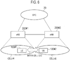
- Fig. 6 is a diagram illustrating an operation environment according to the first embodiment.
- an eNB 200#1 forms a cell #1
- an eNB 200#2 forms a cell #2.
- the cell #1 and the cell #2 are in a relationship where the both are adjacent to each other.
- the UE 100#1 exists in the cell #1.
- the UE 100#1 is in a RRC connected state or a RRC idle state in the cell #1.
- the cell #1 is a serving cell and the cell #2 is a neighbor cell.
- the UE 100#2 exists in the cell #2.
- the UE 100#2 is in a RRC connected state or a RRC idle state in the cell #2.
- the cell #1 is a neighbor cell and the cell #2 is a serving cell.
- a scenario is assumed where the UE 100#1 performs the Inter-Cell Discovery with the UE 100#2. Further, a scenario is assumed where the cell #2 is not synchronized with the cell #1. When the cell #2 is not synchronized with the cell #1, the UE 100#1 is non-synchronized with the UE 100#2, and thus, it is highly probable that the Inter-Cell Discovery with the UE 100#2 is failed even when the UE 100#1 tries.
- Fig. 7 is a sequence diagram illustrating an operation according to the first embodiment.
- step S101 the eNB 200#1 transmits the inter-cell synchronization information on whether the cell #2 (neighbor cell) is synchronized with the cell #1 (serving cell).
- the UE 100#1 receives the inter-cell synchronization information from the eNB 200#1.
- the inter-cell synchronization information is transmitted by a broadcast signal.
- the inter-cell synchronization information may be transmitted by a unicast signal.
- the inter-cell synchronization information preferably includes an identifier of the cell #2.
- the inter-cell synchronization information may be included in the same message as the D2D resource information.
- the UE 100#1 determines, on the basis of the inter-cell synchronization information, whether to perform an inter-cell synchronization procedure (Inter-Cell Synchronization) to establish the synchronization with the UE 100#2 (proximal terminal). Specifically, the UE 100#1 determines that the Inter-Cell Synchronization is unnecessary when the cell #2 is synchronized with the cell #1. On the other hand, the UE 100#1 determines that the Inter-Cell Synchronization is performed when the cell #2 is not synchronized with the cell #1.
- Inter-Cell Synchronization Inter-cell Synchronization procedure
- step S103 the Inter-Cell Synchronization is performed in step S103.
- step S104 the UE 100#1 performs the Inter-Cell Discovery with the UE 100#2.
- the UE 100#1 receives the inter-cell synchronization information from the eNB 200#1 forming the cell #1 (serving cell).
- the UE 100#1 determines whether to perform the Inter-Cell Synchronization for establishing the synchronization with the UE 100#2 on the basis of the inter-cell synchronization information, before performing the Inter-Cell Discovery with the UE 100#2 (proximal terminal) that exists in the cell #2 (neighbor cell).
- the UE 100#1 is capable of performing the Inter-Cell Synchronization after confirming that the cell #2 is not synchronized with the cell #1. Therefore, it is possible to appropriately perform the Inter-Cell Discovery after establishing the synchronization with the UE 100#2.
- the UE 100#1 is capable of omitting the Inter-Cell Synchronization. Therefore, it is possible to restrain an increase in process load, interference, etc., caused as a result of performing an unnecessary Inter-Cell Synchronization.
- the UE 100#1 transmits a D2D SS (D2D synchronization signal).
- the UE 100#2 that receives the D2D SS is capable of being synchronized with the UE 100#1.
- the synchronization between the UE 100#1 and the UE 100#2 is established.
- the UE 100#2 that receives the D2D SS is capable of being synchronized with the UE 100#1.
- the synchronization between the UE 100#1 and the UE 100#2 is directly established.
- the UE 100#1 may scan the D2D SS transmitted from the UE 100#2. As a result of the scan, the UE 100#1 may start transmitting the D2D SS when the D2D SS transmitted from the UE 100#2 is not detected. Note that it is assumed that the D2D SS includes information indicating a serving cell of a UE from which the D2D SS is transmitted.
- the D2D SS is used in a case of the Out of coverage or the Partial coverage; however, in the first embodiment, the D2D SS is exchanged in a case of the In coverage.
- the inter-cell synchronization information transmitted from the eNB 200#1 may include a 1-bit flag indicating whether the cell #2 is synchronized with the cell #1.
- the flag is associated with the identifier of the cell #2.
- the UE 100#1 starts transmitting (or scanning) the D2D SS, determining that the Inter-Cell Synchronization is performed, when the flag indicates that the cell #2 is not synchronized with the cell #1.
- the inter-cell synchronization information transmitted from the eNB 200#1 is information indicating a synchronization deviation amount between the cell #1 (serving cell) and the cell #2 (neighbor cell).
- the information indicating the synchronization deviation amount includes a radio frame offset value of the cell #2 relative to the cell #1, a subframe offset value of the cell #2 relative to the cell #1, etc.
- the eNB 200#1 may transmit the inter-cell synchronization information on the cell #2, only when the cell #2 is not synchronized with the cell #1. That is, then eNB 200#1 may not transmit the inter-cell synchronization information on the cell #2, when the cell #2 is synchronized with the cell #1. In this case, the UE 100#1 determines that the Inter-Cell Synchronization is performed when receiving the inter-cell synchronization information on the cell #2 from the eNB 200#1.
- the eNB 200#1 may transmit the inter-cell synchronization information on the cell #2 also when the cell #2 is synchronized with the cell #1.
- the offset value indicating the synchronization deviation amount is set to zero.
- the UE 100#1 determines that the Inter-Cell Synchronization is performed when receiving the inter-cell synchronization information including an offset value greater than zero.
- the UE 100#1 controls to be synchronized with the cell #2 in accordance with the synchronization deviation amount. For example, adjustment of a transmission timing of the Discovery signal and/or adjustment of a reception timing of the Discovery signal are performed. As a result of the UE 100#1 controlling to be synchronized with the cell #2 in accordance with the synchronization deviation amount, synchronization between the UE 100#1 and the UE 100#2 is established.
- each UE 100 that performs the Inter-Cell Synchronization exchanges the D2D SS in "In coverage", and thus, it may be possible that interference increase resulting from the D2D SS.
- an increase in interference is restrained by restraining the transmission of the D2D SS.
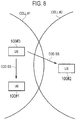
- Fig. 8 is a diagram illustrating the operation environment according to the second embodiment.
- the UE 100#1 and the UE 100#3 exist in a coverage of the cell #1. Further, the UE 100#2 exists in a coverage of the cell #2.
- Each of the UE 100#1 to the UE 100#3 is a UE 100 that performs the Inter-Cell Synchronization to perform the Inter-Cell Discovery.
- the UE 100#3 is located near the UE 100#1 and transmits a D2D SS.
- the D2D SS includes information indicating a serving cell of the transmission source.
- Each of the UE 100-1 and the UE 100-2 receives the D2D SS from the UE 100#3.
- the UE 100#2 establishes the synchronization with the UE 100#3 by using the D2D SS in response to reception of the D2D SS from the UE 100#3 on the neighbor cell.
- the UE 100#1 and the UE 100#3 that exist in the identical cell are synchronized with each other, and thus, this means that the UE 100#2 establishes the synchronization with the UE 100#1 simultaneously of establishing the synchronization with the UE 100#3.
- the UE 100#1 does not need to transmit the D2D SS.
- the UE 100#1 scans the D2D SS transmitted from the UE 100#3 (another UE) that exists in the cell #1 (serving cell), before performing the Inter-Cell Discovery with the UE 100#2 (proximal terminal) that exists in the cell #2 (neighbor cell).
- the UE 100#1 cancels transmission of the D2D SS from the UE 100#1 on the basis of detection of the D2D SS transmitted from the UE 100#3 that exists in the cell #1.
- the UE 100#1 detects the D2D SS transmitted from the UE 100#3 that exists in the cell #1 and a reception level of the detected D2D SS exceeds a threshold value
- the UE 100#1 preferably cancels transmission of the D2D SS from the UE 100#1.
- Fig. 9 is a flowchart illustrating an operation of the UE 100#1 according to the second embodiment.
- the UE 100#1 starts the present flow when determining that the Inter-Cell Discovery is performed.
- step S201 the UE 100#1 scans the D2D SS to measure the reception level of the received D2D SS.
- step S202 the UE 100#1 determines whether the serving cell identifier included in the D2D SS matches the cell identifier of the cell #1. When matching, the UE 100#1 determines whether the reception level of the D2D SS exceeds a threshold value.
- step S203 the UE 100#1 starts (or continues) transmitting the D2D SS.
- step S204 the UE 100#1 cancels transmitting the D2D SS.
- the UE 100#1 that exists in the cell #1 cancels transmitting the D2D SS from the UE 100#1 on the basis of detection of the D2D SS transmitted from the other UE that exists in the cell #1.
- the UE takes the initiative to control the transmission of the D2D SS.
- the eNB may take the initiative to control the transmission of the D2D SS.
- a case is assumed where it is not possible to transmit the D2D SS if it is not possible to obtain permission from the eNB 200.
- a basic concept is similar to that of the second embodiment.
- Fig. 10 is a sequence diagram illustrating an operation according to the modification of the second embodiment.
- the UE 100#1 and the UE 100#3 exist in the cell #1 formed by the eNB 200#1.
- the UE 100#3 transmits, to the eNB 200#1, an inquiry as to whether it is possible to transmit the D2D SS.
- the inquiry may include geological location information of the UE 100#3.
- the eNB 200#1 determines whether to permit transmission of the D2D SS, on the inquiry from the UE 100#3.
- description proceeds with an assumption where permission of the transmission of the D2D SS is given to the UE 100#3.
- the eNB 200#1 stores information on the UE 100#3 in which the transmission of the D2D SS is permitted.
- step S302 the eNB 200#1 notifies the UE 100#3 of transmission permission of the D2D SS.
- the UE 100#3 starts transmitting the D2D SS once the transmission of the D2D SS is permitted.
- step S303 the UE 100#1 transmits, to the eNB 200#1, an inquiry as to whether it is possible to transmit the D2D SS.
- the inquiry may include geological location information on the UE 100#1.
- step S304 the eNB 200#1 determines whether to permit transmission of the D2D SS, on the inquiry from the UE 100#1.
- the eNB 200#1 already permits the UE 100#3 to transmit the D2D SS, that is, the UE 100#3 is transmitting the D2D SS, and thus, the eNB 200#1 may determine that the transmission by the UE 100#1 of the D2D SS is not permitted.
- the eNB 200#1 may determine that the transmission, by the UE 100#1, of the D2D SS is not permitted. In this case, the eNB 200#1 may determine on the basis of the geological location information included in the inquiry whether there is the UE 100#3 near the UE 100#1.
- the eNB 200#1 may make a determination on the basis of the pathloss value, the uplink transmission power value, or the TA value, instead of the geological location information.
- TA timing advance
- step S305 the eNB 200#1 notifies the UE 100#1 of prohibition of transmission (denial) of the D2D SS.
- the UE 100#1 does not start transmitting the D2D SS because the transmission of the D2D SS is not permitted.
- the UE 100 that stops transmitting the D2D SS inquires or notifies the eNB 200#1 to that effect.
- an LTE system is described as an example of a mobile communication system
- the present invention is not limited to the LTE system, and may be applied to a system other than the LTE system.
- the eNB may provide D2D reception discovery resources in SIB. These may cover resources used for D2D transmission in this cell as well as resources used in neighbour cells. (Details FFS)
- a radio resource pool(s) may be provided by eNB for D2D UEs in SIB for discovery reception for Type-2B (if supported). FFS whether the common reception pool(s) or different reception pools for type 1 and Type-2B discovery. UE is not required to decode neighbor cell SIB.
- a resource hopping mechanism following the resource allocation by eNB can be applied.
- serving cell is synchronized with neighbouring cells, so that D2D UEs can perform inter-cell discovery transmission/reception by referring the synchronization signal transmitted from serving cell. Therefore, serving cell is not required to transmit additional information other than reception resource pools.
- Synchronous deployment can be achieved by OAM and eNB implementation. For example, synchronous deployments may be assumed within each MBSFN area.
- serving cell is not synchronized with neighbouring cells, so that D2D UE in serving cell is required to be synchronized with D2D UE in neighbouring cell before performing inter-cell discovery transmission/reception.
- inter-cell discovery both types of deployment are assumed, therefore, inter-cell discovery should also be considered for both types of deployment.
- inter-cell discovery should also be considered for both types of deployment.
- common scheme to perform inter-cell discovery should be introduced for both synchronous and asynchronous deployment. It is assumed the scheme can be classified based on whether or not D2D UEs perform direct synchronization with other D2D UEs for inter-cell discovery.
- the in-coverage D2D UE transmits D2DSS or receives D2DSS transmitted by D2D UE in the neighbouring cell before performing inter-cell discovery in order to be synchronized with D2D UE in the neighbouring cell. Since this scheme assumes direct synchronization with other D2D UEs, it does not matter whether or not the neighbouring cell is synchronized with the serving cell; therefore, this scheme is applicable for both synchronous and asynchronous deployments.
- in-coverage D2D UE transmits D2DSS before transmitting discovery signal to D2DUE in neighbouring cell.
- in-coverage D2D UE monitors D2DSS transmitted by D2D UE in neighbouring cell before receiving discovery signal from D2D UE in neighbouring cell.
- One of the drawbacks of this scheme is the increased interference among D2DSS transmissions within NW coverage. Therefore, further enhancement is needed to minimize the number of D2D UEs transmitting D2DSS for inter-cell discovery.
- the serving cell should inform the in-coverage D2D UE of the neighbouring cell's timing in order to perform inter-cell discovery on the asynchronous deployment, so that the in-coverage D2D UE can perform inter-cell discovery transmission/reception without transmitting/receiving D2DSS irrespective of whether or not the neighbouring cell is synchronized with the serving cell. It is assumed that neighbouring cell's timing can be provided to the serving cell by OAM as well as neighbouring cell's reception resource pools. Therefore, serving cell should provide this timing information to D2D UEs as well as neighbour cells' reception resource pools.
- RAN2 should consider which alternative should be adopted for inter-cell D2D discovery.
- Proposal 1 RAN2 should discuss which alternative should be adopted for inter-cell D2D discovery.
- Proposal 2 If Alt.2 is agreed, the serving cell should provide timing information as well as reception resource pools.
- the present invention is useful for communication fields.
Description
- The present invention relates to a user terminal and a base station which are used in a mobile communication system.
- In 3GPP (3rd Generation Partnership Project) which is a project aiming to standardize a mobile communication system, the introduction of a Device-to-Device (D2D) proximity service is discussed as a new function on and after Release 12 (see Non Patent Document 1).
- The D2D proximity service (D2D ProSe) is a service enabling direct device-to-device communication within a synchronization cluster including a plurality of synchronized user terminals. The D2D proximity service includes a discovery procedure (Discovery) in which a proximal terminal is discovered and D2D communication (Communication) that is direct device-to-device communication.
- Further, a discovery procedure in which a user terminal that exists in a certain cell (serving cell) discovers a proximal terminal that exists in other cell (neighbor cell) is called an inter-cell discovery procedure (Inter-Cell Discovery). Further, D2D communication in which a user terminal that exists in a serving cell performs communication with a proximal terminal that exists in a neighbor cell is called an inter-cell D2D communication (Inter-Cell Communication).
- [Non Patent Document 1] 3GPP technical report "TR 36.843 V12.0.1" March, 2014 3GPP proposal: "On D2D Discovery Transmission Timing", Intel Corporation, R1-135955. It describes inter-cell discovery and synchronization.
- The present invention provides a user terminal according to
claim 1, a method according toclaim 3 and a base station according to claim 4. A further embodiment of the present invention is described in thedependent claim 2. -
- [
Fig. 1] Fig. 1 is a configuration diagram of an LTE system according to a first embodiment and a second embodiment. - [
Fig. 2] Fig. 2 is a block diagram of a UE according to the first embodiment and the second embodiment. - [
Fig. 3] Fig. 3 is a block diagram of an eNB according to the first embodiment and the second embodiment. - [
Fig. 4] Fig. 4 is a protocol stack diagram of a radio interface according to the first embodiment and the second embodiment. - [
Fig. 5] Fig. 5 is a configuration diagram of a radio frame used in the LTE system according to the first embodiment and the second embodiment. - [
Fig. 6] Fig. 6 is a diagram illustrating an operation environment according to the first embodiment. - [
Fig. 7] Fig. 7 is a sequence diagram illustrating an operation according to the first embodiment. - [
Fig. 8] Fig. 8 is a diagram illustrating an operation environment according to the second embodiment. - [
Fig. 9] Fig. 9 is a flowchart illustrating an operation of the UE according to the second embodiment. - [
Fig. 10] Fig. 10 is a sequence diagram illustrating an operation according to a modification of the second embodiment. - A case where the present invention is applied to an LTE system that is a mobile communication system based on 3GPP standards will be described, below.
- First of all, the configuration of an LTE system according to a first embodiment will be described.
Fig. 1 is a configuration diagram of the LTE system according to the first embodiment. - As illustrated in
Fig. 1 , the LTE system according to the first embodiment includes UE (User Equipment) 100, E-UTRAN (Evolved-UMTS Terrestrial Radio Access Network) 10, and EPC (Evolved Packet Core) 20. - The UE 100 corresponds to a user terminal. The UE 100 is a mobile communication device, which performs radio communication with a cell (a serving cell). The configuration of the UE 100 will be described later.
- The
E-UTRAN 10 corresponds to a radio access network. TheE-UTRAN 10 includes eNB 200 (an evolved Node-B). The eNB 200 corresponds to a base station. The eNBs 200 are connected mutually via an X2 interface. The configuration of the eNB 200 will be described later. - The eNB 200 manages one or a plurality of cells, and performs radio communication with the UE 100 that establishes a connection with a cell of the eNB 200. The eNB 200 has a radio resource management (RRM) function, a routing function of user data, a measurement control function for mobility control and scheduling and the like. The "cell" is used as a term indicating a smallest unit of a radio communication area, and is also used as a term indicating a function of performing radio communication with the UE 100.
- The
EPC 20 corresponds to a core network. TheEPC 20 includes MME (Mobility Management Entity)/S-GW (Serving-Gateway) 300. The MME performs different types of mobility control and the like for the UE 100. The S-GW performs transfer control of the user data. The MME/S-GW 300 is connected to the eNB 200 via an S1 interface. It is noted that theE-UTRAN 10 and theEPC 20 constitute a network of the LTE system. -
Fig. 2 is a block diagram of the UE 100. As illustrated inFig. 2 , the UE 100 includes a plurality ofantennas 101, aradio transceiver 110, auser interface 120, a GNSS (Global Navigation Satellite System)receiver 130, abattery 140, amemory 150, and aprocessor 160. Thememory 150 and theprocessor 160 constitute a controller. The UE 100 may not necessarily have the GNSSreceiver 130. Furthermore, thememory 150 may be integrally formed with theprocessor 160, and this set (that is, a chip set) may be called a processor 160'. - The
antenna 101 and theradio transceiver 110 are used to transmit and receive a radio signal. Theradio transceiver 110 converts a baseband signal (a transmission signal) output from theprocessor 160 into a radio signal, and transmits the radio signal from theantenna 101. Furthermore, theradio transceiver 110 converts a radio signal received by theantenna 101 into a baseband signal (a reception signal), and outputs the baseband signal to theprocessor 160. - The
user interface 120 is an interface with a user carrying the UE 100, and includes, for example, a display, a microphone, a speaker, and various buttons. Theuser interface 120 receives an operation from a user and outputs a signal indicating the content of the operation to theprocessor 160. The GNSSreceiver 130 receives a GNSS signal in order to obtain location information indicating a geographical location of the UE 100, and outputs the received signal to theprocessor 160. Thebattery 140 accumulates a power to be supplied to each block of the UE 100. - The
memory 150 stores a program to be executed by theprocessor 160 and information to be used for processing by theprocessor 160. Theprocessor 160 includes a baseband processor that performs modulation and demodulation, encoding and decoding and the like on the baseband signal, and a CPU (Central Processing Unit) that performs various types of processes by executing the program stored in thememory 150. Theprocessor 160 may further include a codec that performs encoding and decoding on sound and video signals. Theprocessor 160 executes various types of processes and various types of communication protocols described later. -
Fig. 3 is a block diagram of the eNB 200. As illustrated inFig. 3 , theeNB 200 includes a plurality ofantennas 201, aradio transceiver 210, anetwork interface 220, amemory 230, and aprocessor 240. Thememory 230 and theprocessor 240 configure a controller. Furthermore, thememory 230 may be integrally formed with theprocessor 240, and this set (that is, a chipset) may be called a processor. - The
antenna 201 and theradio transceiver 210 are used to transmit and receive a radio signal. Theradio transceiver 210 converts a baseband signal (a transmission signal) output from theprocessor 240 into a radio signal, and transmits the radio signal from theantenna 201. Furthermore, theradio transceiver 210 converts a radio signal received by theantenna 201 into a baseband signal (a reception signal), and outputs the baseband signal to theprocessor 240. - The
network interface 220 is connected to the neighboringeNB 200 via the X2 interface and is connected to the MME/S-GW 300 via the S1 interface. Thenetwork interface 220 is used in communication performed on the X2 interface and communication performed on the S1 interface. - The
memory 230 stores a program to be executed by theprocessor 240 and information to be used for processing by theprocessor 240. Theprocessor 240 includes a baseband processor that performs modulation and demodulation, encoding and decoding and the like on the baseband signal and a CPU that performs various types of processes by executing the program stored in thememory 230. Theprocessor 240 executes various types of processes and various types of communication protocols described later. -
Fig. 4 is a protocol stack diagram of a radio interface in the LTE system. As illustrated inFig. 4 , the radio interface protocol is classified into a first layer to a third layer of an OSI reference model, such that the first layer is a physical (PHY) layer. The second layer includes a MAC (Medium Access Control) layer, an RLC (Radio Link Control) layer, and a PDCP (Packet Data Convergence Protocol) layer. The third layer includes an RRC (Radio Resource Control) layer. - The physical layer performs encoding and decoding, modulation and demodulation, antenna mapping and demapping, and resource mapping and demapping. Between the physical layer of the
UE 100 and the physical layer of theeNB 200, user data and control signals are transmitted via a physical channel. - The MAC layer performs priority control of data, a retransmission process by a hybrid ARQ (HARQ), a random access procedure, and the like. Between the MAC layer of the
UE 100 and the MAC layer of theeNB 200, user data and control signals are transmitted via a transport channel. The MAC layer of theeNB 200 includes a scheduler for determining a transport format (a transport block size and a modulation and coding scheme) of an uplink and a downlink, and resource blocks to be assigned to theUE 100. - The RLC layer transmits data to an RLC layer of a reception side by using the functions of the MAC layer and the physical layer. Between the RLC layer of the
UE 100 and the RLC layer of theeNB 200, user data and control signals are transmitted via a logical channel. - The PDCP layer performs header compression and decompression, and encryption and decryption.
- The RRC layer is defined only in a control plane that handles control signals. Between the RRC layer of the
UE 100 and the RRC layer of theeNB 200, a control signal (an RRC message) for various types of settings is transmitted. The RRC layer controls a logical channel, a transport channel, and a physical channel according to the establishment, re-establishment, and release of a radio bearer. When there is a connection (an RRC connection) between the RRC of theUE 100 and the RRC of theeNB 200, theUE 100 is in an RRC connected state. Otherwise, theUE 100 is in an RRC idle state. - An NAS (Non-Access Stratum) layer positioned above the RRC layer performs session management, mobility management and the like.
-
Fig. 5 is a configuration diagram of a radio frame used in the LTE system. In the LTE system, OFDMA (Orthogonal Frequency Division Multiple Access) is applied to a downlink, and SC-FDMA (Single Carrier Frequency Division Multiple Access) is applied to an uplink, respectively. - As illustrated in
Fig. 5 , a radio frame is configured by 10 subframes arranged in a time direction. Each subframe is configured by two slots arranged in the time direction. Each subframe has a length of 1 ms and each slot has a length of 0.5 ms. Each subframe includes a plurality of resource blocks (RBs) in a frequency direction, and a plurality of symbols in the time direction. Each resource block includes a plurality of subcarriers in the frequency direction. One symbol and one subcarrier form a one resource element. Of the radio resources (time and frequency resources) assigned to theUE 100, a frequency resource can be identified by a resource block and a time resource can be identified by a subframe (or a slot). - A D2D proximity service will be described, below. An LTE system according to the first embodiment supports the D2D proximity service.
- The D2D proximity service (D2D ProSe) is a service enabling direct UE-to-UE communication within a synchronization cluster including a plurality of
synchronized UEs 100. The D2D proximity service includes a discovery procedure (Discovery) in which a proximal UE is discovered and D2D communication (Communication) that is direct UE-to-UE communication. The D2D communication is also called Direct communication. - A scenario in which all the
UEs 100 forming the synchronization cluster are located inside a cell coverage is called "In coverage". A scenario in which all theUEs 100 forming the synchronization cluster are located outside a cell coverage is called "Out of coverage". A scenario in which someUEs 100 in the synchronization cluster are located inside a cell coverage and the remainingUEs 100 are located outside the cell coverage is called "Partial coverage". - In "In coverage", the
eNB 200 is a D2D synchronization source. A D2D non-synchronization source, from which a D2D synchronization signal is not transmitted, is synchronized with the D2D synchronization source. TheeNB 200 that is a D2D synchronization source transmits, by a broadcast signal, D2D resource information indicating radio resources (resource pool) available for the D2D proximity service. The D2D resource information includes information indicating a resource pool for the discovery procedure (Discovery resource information) and information indicating a resource pool for the D2D communication (Communication resource information), for example. TheUE 100 that is a D2D non-synchronization source performs the discovery procedure and the D2D communication on the basis of the D2D resource information received from theeNB 200. - In "Out of coverage" or "Partial coverage", the
UE 100 is a D2D synchronization source. In "Out of coverage", theUE 100 that is a D2D synchronization source transmits D2D resource information indicating radio resources (resource pool) available for the D2D proximity service, by a D2D synchronization signal, for example. The D2D synchronization signal is a signal transmitted in the synchronization procedure in which a device-to-device synchronization is established. The D2D synchronization signal includes a D2D SS and a physical D2D synchronization channel (PD2DSCH). The D2D SS is a signal for providing a synchronization standard of a time and a frequency. The PD2DSCH is a physical channel through which a greater amount of information can be conveyed than the D2D SS can. The PD2DSCH conveys the above-described D2D resource information (the Discovery resource information and the Communication resource information). Alternatively, when the D2D SS is associated with the D2D resource information, the PD2DSCH may be rendered unnecessary. - The discovery procedure is used mainly when the D2D communication is performed by unicast. When starting the D2D communication with another
UE 100, oneUE 100 uses any particular radio resource in the resource pool for the discovery procedure to transmit the Discovery signal. When starting the D2D communication with the oneUE 100, theother UE 100 scans the Discovery signal within the resource pool for the discovery procedure to receive the Discovery signal. The Discovery signal may include information indicating radio resources used by the oneUE 100 for the D2D communication. - Further, a discovery procedure in which a user terminal that exists in a certain cell (serving cell) discovers a proximal terminal that exists in another cell (neighbor cell) is called an inter-cell discovery procedure (Inter-Cell Discovery). Further, D2D communication in which a user terminal that exists in a serving cell performs communication with a proximal terminal that exists in a neighbor cell is called inter-cell D2D communication (Inter-Cell Communication).
- An operation environment according to the first embodiment will be described, below.
Fig. 6 is a diagram illustrating an operation environment according to the first embodiment. - As illustrated in
Fig. 6 , aneNB 200#1 forms acell # 1, and aneNB 200#2 forms acell # 2. Thecell # 1 and thecell # 2 are in a relationship where the both are adjacent to each other. - The
UE 100#1 exists in thecell # 1. TheUE 100#1 is in a RRC connected state or a RRC idle state in thecell # 1. When theUE 100#1 is concerned, thecell # 1 is a serving cell and thecell # 2 is a neighbor cell. - The
UE 100#2 exists in thecell # 2. TheUE 100#2 is in a RRC connected state or a RRC idle state in thecell # 2. When theUE 100#2 is concerned, thecell # 1 is a neighbor cell and thecell # 2 is a serving cell. - In the first embodiment, in such an operation environment, a scenario is assumed where the
UE 100#1 performs the Inter-Cell Discovery with theUE 100#2. Further, a scenario is assumed where thecell # 2 is not synchronized with thecell # 1. When thecell # 2 is not synchronized with thecell # 1, theUE 100#1 is non-synchronized with theUE 100#2, and thus, it is highly probable that the Inter-Cell Discovery with theUE 100#2 is failed even when theUE 100#1 tries. - An operation according to the first embodiment will be described, below.
-
Fig. 7 is a sequence diagram illustrating an operation according to the first embodiment. - As illustrated in
Fig. 7 , in step S101, theeNB 200#1 transmits the inter-cell synchronization information on whether the cell #2 (neighbor cell) is synchronized with the cell #1 (serving cell). TheUE 100#1 receives the inter-cell synchronization information from theeNB 200#1. - The inter-cell synchronization information is transmitted by a broadcast signal. Alternatively, the inter-cell synchronization information may be transmitted by a unicast signal. The inter-cell synchronization information preferably includes an identifier of the
cell # 2. The inter-cell synchronization information may be included in the same message as the D2D resource information. - In step S102, the
UE 100#1 determines, on the basis of the inter-cell synchronization information, whether to perform an inter-cell synchronization procedure (Inter-Cell Synchronization) to establish the synchronization with theUE 100#2 (proximal terminal). Specifically, theUE 100#1 determines that the Inter-Cell Synchronization is unnecessary when thecell # 2 is synchronized with thecell # 1. On the other hand, theUE 100#1 determines that the Inter-Cell Synchronization is performed when thecell # 2 is not synchronized with thecell # 1. - When the
cell # 2 is not synchronized with the cell #1 (step S102: NO), the Inter-Cell Synchronization is performed in step S103. There are two patterns for the Inter-Cell Synchronization. Each operation pattern will be described in detail later. - In step S104, the
UE 100#1 performs the Inter-Cell Discovery with theUE 100#2. - Thus, the
UE 100#1 receives the inter-cell synchronization information from theeNB 200#1 forming the cell #1 (serving cell). TheUE 100#1 determines whether to perform the Inter-Cell Synchronization for establishing the synchronization with theUE 100#2 on the basis of the inter-cell synchronization information, before performing the Inter-Cell Discovery with theUE 100#2 (proximal terminal) that exists in the cell #2 (neighbor cell). - Thus, the
UE 100#1 is capable of performing the Inter-Cell Synchronization after confirming that thecell # 2 is not synchronized with thecell # 1. Therefore, it is possible to appropriately perform the Inter-Cell Discovery after establishing the synchronization with theUE 100#2. - On the other hand, when the
cell # 2 is synchronized with thecell # 1, theUE 100#1 is capable of omitting the Inter-Cell Synchronization. Therefore, it is possible to restrain an increase in process load, interference, etc., caused as a result of performing an unnecessary Inter-Cell Synchronization. - Next, an
operation pattern 1 of the Inter-Cell Synchronization will be described. - In the
operation pattern 1, in the Inter-Cell Synchronization, theUE 100#1 transmits a D2D SS (D2D synchronization signal). TheUE 100#2 that receives the D2D SS is capable of being synchronized with theUE 100#1. Thus, the synchronization between theUE 100#1 and theUE 100#2 is established. - The
UE 100#2 that receives the D2D SS is capable of being synchronized with theUE 100#1. Thus, the synchronization between theUE 100#1 and theUE 100#2 is directly established. - Alternatively, in the Inter-Cell Synchronization, the
UE 100#1 may scan the D2D SS transmitted from theUE 100#2. As a result of the scan, theUE 100#1 may start transmitting the D2D SS when the D2D SS transmitted from theUE 100#2 is not detected. Note that it is assumed that the D2D SS includes information indicating a serving cell of a UE from which the D2D SS is transmitted. - As described above, the D2D SS is used in a case of the Out of coverage or the Partial coverage; however, in the first embodiment, the D2D SS is exchanged in a case of the In coverage.
- In the
operation pattern 1, the inter-cell synchronization information transmitted from theeNB 200#1 may include a 1-bit flag indicating whether thecell # 2 is synchronized with thecell # 1. In the inter-cell synchronization information, the flag is associated with the identifier of thecell # 2. - The
UE 100#1 starts transmitting (or scanning) the D2D SS, determining that the Inter-Cell Synchronization is performed, when the flag indicates that thecell # 2 is not synchronized with thecell # 1. - Next, an
operation pattern 2 of the Inter-Cell Synchronization will be described. - In the
operation pattern 2, the inter-cell synchronization information transmitted from theeNB 200#1 is information indicating a synchronization deviation amount between the cell #1 (serving cell) and the cell #2 (neighbor cell). The information indicating the synchronization deviation amount includes a radio frame offset value of thecell # 2 relative to thecell # 1, a subframe offset value of thecell # 2 relative to thecell # 1, etc. - In the
operation pattern 2, theeNB 200#1 may transmit the inter-cell synchronization information on thecell # 2, only when thecell # 2 is not synchronized with thecell # 1. That is, theneNB 200#1 may not transmit the inter-cell synchronization information on thecell # 2, when thecell # 2 is synchronized with thecell # 1. In this case, theUE 100#1 determines that the Inter-Cell Synchronization is performed when receiving the inter-cell synchronization information on thecell # 2 from theeNB 200#1. - Alternatively, the
eNB 200#1 may transmit the inter-cell synchronization information on thecell # 2 also when thecell # 2 is synchronized with thecell # 1. In this case, the offset value indicating the synchronization deviation amount is set to zero. In this case, theUE 100#1 determines that the Inter-Cell Synchronization is performed when receiving the inter-cell synchronization information including an offset value greater than zero. - In the
operation pattern 2, in the Inter-Cell Synchronization, theUE 100#1 controls to be synchronized with thecell # 2 in accordance with the synchronization deviation amount. For example, adjustment of a transmission timing of the Discovery signal and/or adjustment of a reception timing of the Discovery signal are performed. As a result of theUE 100#1 controlling to be synchronized with thecell # 2 in accordance with the synchronization deviation amount, synchronization between theUE 100#1 and theUE 100#2 is established. - A difference of the second embodiment from the first embodiment will be mainly described. In the second embodiment, a case is assumed where the
operation pattern 1 of the above-described Inter-Cell Synchronization is applied. - In the
operation pattern 1 of the above-described Inter-Cell Synchronization, eachUE 100 that performs the Inter-Cell Synchronization exchanges the D2D SS in "In coverage", and thus, it may be possible that interference increase resulting from the D2D SS. Thus, in the second embodiment, in theoperation pattern 1 of the above-described Inter-Cell Synchronization, an increase in interference is restrained by restraining the transmission of the D2D SS. - An operation environment according to the second embodiment will be described, below.
Fig. 8 is a diagram illustrating the operation environment according to the second embodiment. - As illustrated in
Fig. 8 , theUE 100#1 and theUE 100#3 exist in a coverage of thecell # 1. Further, theUE 100#2 exists in a coverage of thecell # 2. Each of theUE 100#1 to theUE 100#3 is aUE 100 that performs the Inter-Cell Synchronization to perform the Inter-Cell Discovery. - The
UE 100#3 is located near theUE 100#1 and transmits a D2D SS. As described above, the D2D SS includes information indicating a serving cell of the transmission source. - Each of the UE 100-1 and the UE 100-2 receives the D2D SS from the
UE 100#3. TheUE 100#2 establishes the synchronization with theUE 100#3 by using the D2D SS in response to reception of the D2D SS from theUE 100#3 on the neighbor cell. - Here, the
UE 100#1 and theUE 100#3 that exist in the identical cell are synchronized with each other, and thus, this means that theUE 100#2 establishes the synchronization with theUE 100#1 simultaneously of establishing the synchronization with theUE 100#3. Thus, theUE 100#1 does not need to transmit the D2D SS. - An operation according to the second embodiment will be described, below.
- The
UE 100#1 according to the second embodiment scans the D2D SS transmitted from theUE 100#3 (another UE) that exists in the cell #1 (serving cell), before performing the Inter-Cell Discovery with theUE 100#2 (proximal terminal) that exists in the cell #2 (neighbor cell). - Then, the
UE 100#1 cancels transmission of the D2D SS from theUE 100#1 on the basis of detection of the D2D SS transmitted from theUE 100#3 that exists in thecell # 1. Here, when theUE 100#1 detects the D2D SS transmitted from theUE 100#3 that exists in thecell # 1 and a reception level of the detected D2D SS exceeds a threshold value, theUE 100#1 preferably cancels transmission of the D2D SS from theUE 100#1. -
Fig. 9 is a flowchart illustrating an operation of theUE 100#1 according to the second embodiment. For example, theUE 100#1 starts the present flow when determining that the Inter-Cell Discovery is performed. - As illustrated in
Fig. 9 , in step S201, theUE 100#1 scans the D2D SS to measure the reception level of the received D2D SS. - In step S202, the
UE 100#1 determines whether the serving cell identifier included in the D2D SS matches the cell identifier of thecell # 1. When matching, theUE 100#1 determines whether the reception level of the D2D SS exceeds a threshold value. - When "NO" in step S202, in step S203, the
UE 100#1 starts (or continues) transmitting the D2D SS. On the other hand, when "YES" in step S202, in step S204, theUE 100#1 cancels transmitting the D2D SS. - Thus, in the inter-Cell Synchronization, the
UE 100#1 that exists in thecell # 1 cancels transmitting the D2D SS from theUE 100#1 on the basis of detection of the D2D SS transmitted from the other UE that exists in thecell # 1. Thus, it is possible to restrain transmission of the D2D SS. - In the above-described second embodiment, the UE takes the initiative to control the transmission of the D2D SS. However, the eNB may take the initiative to control the transmission of the D2D SS. In a modification of the second embodiment, a case is assumed where it is not possible to transmit the D2D SS if it is not possible to obtain permission from the
eNB 200. However, a basic concept is similar to that of the second embodiment. - An operation according to the modification of the second embodiment will be described, below. Here, an operation in an operation environment as illustrated in
Fig. 8 will be described. -
Fig. 10 is a sequence diagram illustrating an operation according to the modification of the second embodiment. InFig. 10 , theUE 100#1 and theUE 100#3 exist in thecell # 1 formed by theeNB 200#1. - As illustrated in
Fig. 10 , in step S301, theUE 100#3 transmits, to theeNB 200#1, an inquiry as to whether it is possible to transmit the D2D SS. The inquiry may include geological location information of theUE 100#3. TheeNB 200#1 determines whether to permit transmission of the D2D SS, on the inquiry from theUE 100#3. Here, description proceeds with an assumption where permission of the transmission of the D2D SS is given to theUE 100#3. TheeNB 200#1 stores information on theUE 100#3 in which the transmission of the D2D SS is permitted. - In step S302, the
eNB 200#1 notifies theUE 100#3 of transmission permission of the D2D SS. TheUE 100#3 starts transmitting the D2D SS once the transmission of the D2D SS is permitted. - In step S303, the
UE 100#1 transmits, to theeNB 200#1, an inquiry as to whether it is possible to transmit the D2D SS. The inquiry may include geological location information on theUE 100#1. - In step S304, the
eNB 200#1 determines whether to permit transmission of the D2D SS, on the inquiry from theUE 100#1. TheeNB 200#1 already permits theUE 100#3 to transmit the D2D SS, that is, theUE 100#3 is transmitting the D2D SS, and thus, theeNB 200#1 may determine that the transmission by theUE 100#1 of the D2D SS is not permitted. - Alternatively, when the permission of the transmission of the D2D SS is already given to the
UE 100#3 and it is estimated that there is theUE 100#3 near theUE 100#1, theeNB 200#1 may determine that the transmission, by theUE 100#1, of the D2D SS is not permitted. In this case, theeNB 200#1 may determine on the basis of the geological location information included in the inquiry whether there is theUE 100#3 near theUE 100#1. Alternatively, when theeNB 200#1 manages a pathloss value of eachUE 100, an uplink transmission power value, or a timing advance (TA) value, theeNB 200#1 may make a determination on the basis of the pathloss value, the uplink transmission power value, or the TA value, instead of the geological location information. - Here, description proceeds with an assumption where permission of transmission of the D2D SS is not given to the
UE 100#1. - In step S305, the
eNB 200#1 notifies theUE 100#1 of prohibition of transmission (denial) of the D2D SS. TheUE 100#1 does not start transmitting the D2D SS because the transmission of the D2D SS is not permitted. - Thus, according to the modification of the second embodiment, similarly to the above-described second embodiment, it is possible to restrain transmission of the D2D SS.
- It is noted that in the modification of the second embodiment, in order to manage a transmission status of the D2D SS by the
eNB 200#1, it is preferable that theUE 100 that stops transmitting the D2D SS inquires or notifies theeNB 200#1 to that effect. - In above-described each embodiment, a scenario is assumed where the
UE 100#1 performs the Inter-Cell Discovery with theUE 100#2. However, the present invention may be also applied to a scenario where theUE 100#1 performs the Inter-Cell Communication with theUE 100#2 while theUE 100#1 does not perform the Inter-Cell Discovery with theUE 100#2. That is, the "Inter-Cell Discovery" in the operation according to above-described each embodiment can be replaced by the "Inter-Cell Communication". - Furthermore, in the embodiment described above, although an LTE system is described as an example of a mobile communication system, the present invention is not limited to the LTE system, and may be applied to a system other than the LTE system.
- Below, supplementary notes of the embodiments will be noted.
- As for the inter-cell discovery, a following agreement on D2D reception discovery resource pools is made.
- The eNB may provide D2D reception discovery resources in SIB. These may cover resources used for D2D transmission in this cell as well as resources used in neighbour cells. (Details FFS)
- On the other hand, RAN1 made a following agreement.
- Confirm that a radio resource pool(s) may be provided by eNB for D2D UEs in SIB for discovery reception for Type-2B (if supported). FFS whether the common reception pool(s) or different reception pools for
type 1 and Type-2B discovery. UE is not required to decode neighbor cell SIB. - Mechanisms for Type-2B discovery. A resource hopping mechanism following the resource allocation by eNB can be applied. FFS details of resource hopping mechanism.
- In this additional statements, we will investigate other aspects of inter-cell discovery and propose possible solutions, based on the above agreements.
- Regarding the synchronization among serving cell and neighbouring cells, the following 2 deployments have been considered until last RAN2 meeting.
- For synchronous deployment, serving cell is synchronized with neighbouring cells, so that D2D UEs can perform inter-cell discovery transmission/reception by referring the synchronization signal transmitted from serving cell. Therefore, serving cell is not required to transmit additional information other than reception resource pools. Synchronous deployment can be achieved by OAM and eNB implementation. For example, synchronous deployments may be assumed within each MBSFN area.
- For the asynchronous deployment, serving cell is not synchronized with neighbouring cells, so that D2D UE in serving cell is required to be synchronized with D2D UE in neighbouring cell before performing inter-cell discovery transmission/reception.
- As for the inter-cell discovery, both types of deployment are assumed, therefore, inter-cell discovery should also be considered for both types of deployment. For reducing the complexity, it is considered that common scheme to perform inter-cell discovery should be introduced for both synchronous and asynchronous deployment. It is assumed the scheme can be classified based on whether or not D2D UEs perform direct synchronization with other D2D UEs for inter-cell discovery.
- With direct synchronization, the in-coverage D2D UE transmits D2DSS or receives D2DSS transmitted by D2D UE in the neighbouring cell before performing inter-cell discovery in order to be synchronized with D2D UE in the neighbouring cell. Since this scheme assumes direct synchronization with other D2D UEs, it does not matter whether or not the neighbouring cell is synchronized with the serving cell; therefore, this scheme is applicable for both synchronous and asynchronous deployments.
- To achieve direct synchronization efficiently, in-coverage D2D UE transmits D2DSS before transmitting discovery signal to D2DUE in neighbouring cell. Similarly, in-coverage D2D UE monitors D2DSS transmitted by D2D UE in neighbouring cell before receiving discovery signal from D2D UE in neighbouring cell. One of the drawbacks of this scheme is the increased interference among D2DSS transmissions within NW coverage. Therefore, further enhancement is needed to minimize the number of D2D UEs transmitting D2DSS for inter-cell discovery.
- With this scheme, the serving cell should inform the in-coverage D2D UE of the neighbouring cell's timing in order to perform inter-cell discovery on the asynchronous deployment, so that the in-coverage D2D UE can perform inter-cell discovery transmission/reception without transmitting/receiving D2DSS irrespective of whether or not the neighbouring cell is synchronized with the serving cell. It is assumed that neighbouring cell's timing can be provided to the serving cell by OAM as well as neighbouring cell's reception resource pools. Therefore, serving cell should provide this timing information to D2D UEs as well as neighbour cells' reception resource pools.
- Based on the descriptions of both alternatives above, RAN2 should consider which alternative should be adopted for inter-cell D2D discovery.
- Proposal 1: RAN2 should discuss which alternative should be adopted for inter-cell D2D discovery.
- Proposal 2: If Alt.2 is agreed, the serving cell should provide timing information as well as reception resource pools.
- The present invention is useful for communication fields.
Claims (3)
- A user terminal (100#1) that exists in a serving cell, in a mobile communication system that supports a device-to-device, D2D, proximity service, comprising:a receiver (110) configured to receive a broadcast signal from a base station (200#1) that forms the serving cell, the broadcast signal including a cell identifier of a neighbor cell and inter-cell synchronization information on the neighbor cell; anda controller (160) configured to determine, on the basis of the inter-cell synchronization information, whether or not to perform an inter-cell synchronization procedure including a process of receiving a D2D synchronization signal from a proximal terminal (100#2) that exists in the neighbor cell in order to receive a D2D discovery signal from the proximal terminal (100#2), whereinwhen it is determined that user terminal (100#1) performs the inter-cell synchronization procedure, the controller (160) is configured to perform the inter-cell synchronization procedure and a process of receiving the D2D discovery signal from the proximal terminal (100#2), andwhen it is determined that user terminal (100#1) does not perform the inter-cell synchronization procedure, the controller (160) is configured to perform a process of receiving the D2D discovery signal from the proximal terminal (100#2) without performing the inter-cell synchronization procedure.
- The user terminal (100#1) according to claim 1, wherein
the inter-cell synchronization information includes a first value or a second value,
the controller (160) is configured to determine, on the basis of one of the first value and the second value included in the inter-cell synchronization information, whether or not to perform the inter-cell synchronization procedure in order to receive the D2D discovery signal from the proximal terminal (100#2),
when the first value is included in the inter-cell synchronization information, the controller (160) is configured to perform the inter-cell synchronization procedure and a process of receiving the D2D discovery signal from the proximal terminal (100#2), and
when the second value is included in the inter-cell synchronization information, the controller (160) is configured to perform a process of receiving the D2D discovery signal from the proximal terminal (100#2) without performing the inter-cell synchronization procedure. - A method for a user terminal (100#1) that exists in a serving cell, in a mobile communication system that supports a device-to-device, D2D, proximity service, comprising:receiving a broadcast signal from a base station (200#1) that forms the serving cell, the broadcast signal including a cell identifier of a neighbor cell and inter-cell synchronization information on the neighbor cell;determining, on the basis of the inter-cell synchronization information, whether or not to perform an inter-cell synchronization procedure including a process of receiving a D2D synchronization signal from a proximal terminal (100#2) that exists in the neighbor cell in order to receive a D2D discovery signal from the proximal terminal (100#2),when it is determined that user terminal (100#1) performs the inter-cell synchronization procedure, performing the inter-cell synchronization procedure and a process of receiving the D2D discovery signal from the proximal terminal (100#2); andwhen it is determined that user terminal (100#1) does not perform the inter-cell synchronization procedure, performing a process of receiving the D2D discovery signal from the proximal terminal (100#2) without performing the inter-cell synchronization procedure.
Applications Claiming Priority (2)
| Application Number | Priority Date | Filing Date | Title |
|---|---|---|---|
| US201461990951P | 2014-05-09 | 2014-05-09 | |
| PCT/JP2015/063262 WO2015170730A1 (en) | 2014-05-09 | 2015-05-08 | User terminal and base station |
Publications (3)
| Publication Number | Publication Date |
|---|---|
| EP3142451A1 EP3142451A1 (en) | 2017-03-15 |
| EP3142451A4 EP3142451A4 (en) | 2018-01-10 |
| EP3142451B1 true EP3142451B1 (en) | 2020-03-25 |
Family
ID=54392579
Family Applications (1)
| Application Number | Title | Priority Date | Filing Date |
|---|---|---|---|
| EP15788952.8A Active EP3142451B1 (en) | 2014-05-09 | 2015-05-08 | User terminal and base station |
Country Status (4)
| Country | Link |
|---|---|
| US (3) | US9578614B2 (en) |
| EP (1) | EP3142451B1 (en) |
| JP (2) | JP6142082B2 (en) |
| WO (1) | WO2015170730A1 (en) |
Families Citing this family (12)
| Publication number | Priority date | Publication date | Assignee | Title |
|---|---|---|---|---|
| JP5973967B2 (en) * | 2013-07-19 | 2016-08-23 | 株式会社Nttドコモ | User apparatus, base station, discovery signal reception method, and discovery signal transmission method |
| US20160029334A1 (en) * | 2014-07-25 | 2016-01-28 | Electronics And Telecommunications Research Institute | Method and apparatus for synchronizing networks among heterogeneous wireless operators |
| US10187903B2 (en) * | 2014-07-29 | 2019-01-22 | Lg Electronics Inc. | Method for transceiving signal for device-to-device (D2D) communication and apparatus therefor in wireless communication system |
| JP6311515B2 (en) * | 2014-07-30 | 2018-04-18 | ソニー株式会社 | apparatus |
| JP6434616B2 (en) | 2014-09-24 | 2018-12-05 | エルジー エレクトロニクス インコーポレイティド | D2D signal transmission method and terminal therefor |
| CN107431902B (en) * | 2015-02-06 | 2021-02-19 | 三星电子株式会社 | Method and apparatus for transmitting and receiving signal in communication system supporting device-to-device scheme |
| US10172107B2 (en) * | 2016-03-30 | 2019-01-01 | Lg Electronics Inc. | Method of transmitting SLSS by V2V terminal |
| EP3457745B1 (en) * | 2016-05-13 | 2020-08-19 | Huawei Technologies Co., Ltd. | Resource allocation method and relevant device |
| CN109041105B (en) * | 2017-06-09 | 2020-10-16 | 维沃移动通信有限公司 | Sending method of adjacent cell information, and processing method and device of adjacent cell information |
| JP7265555B2 (en) * | 2018-09-27 | 2023-04-26 | 株式会社Nttドコモ | Terminal, communication system, and communication method |
| US11671930B2 (en) * | 2019-05-29 | 2023-06-06 | Qualcomm Incorporated | Early termination of synchronization procedure |
| US11540224B2 (en) * | 2020-02-11 | 2022-12-27 | Qualcomm Incorporated | Vehicle-to-everything (V2X) inter-user equipment (UE) coordination |
Family Cites Families (17)
| Publication number | Priority date | Publication date | Assignee | Title |
|---|---|---|---|---|
| US9578550B2 (en) * | 2010-05-28 | 2017-02-21 | Nokia Solutions And Networks Oy | Method and apparatus for device-to-device communication |
| US9119202B2 (en) * | 2010-12-13 | 2015-08-25 | Telefonaktiebolaget L M Ericsson (Publ) | Methods and user equipments for device to device communication |
| US20140314057A1 (en) * | 2011-12-08 | 2014-10-23 | Vinh Van Phan | Network Synchronisation of Devices in a D2D Cluster |
| US20140094212A1 (en) * | 2012-09-28 | 2014-04-03 | Electronics And Telecommunications Research Institute | Method of device to device discovery and apparatus thereof |
| US11496948B2 (en) * | 2012-10-19 | 2022-11-08 | Samsung Electronics Co., Ltd. | System and method for ad-hoc/network assisted device discovery protocol for device to device communications |
| US9072027B2 (en) * | 2012-12-07 | 2015-06-30 | Alcatel Lucent | Methods and apparatuses for facilitating D2D bearer switching |
| CN103974225B (en) * | 2013-02-01 | 2018-03-13 | 财团法人工业技术研究院 | Communication device, device-to-device communication system and wireless communication method thereof |
| WO2014173443A1 (en) * | 2013-04-24 | 2014-10-30 | Nokia Solutions And Networks Oy | Mobility management for device-to-device communications |
| US9974066B2 (en) * | 2013-05-01 | 2018-05-15 | Samsung Electronics Co., Ltd. | Methods and apparatus for device-to-device communications system |
| US20150056982A1 (en) * | 2013-08-22 | 2015-02-26 | Telefonaktiebolaget L M Ericsson (Publ) | Methods and Network Nodes for Management of Resources |
| US9392629B2 (en) * | 2013-09-10 | 2016-07-12 | Electronics And Telecommunications Research Institute | Method for setting synchronization between device-to-device communication terminals based on cellular communication system |
| WO2015054903A1 (en) * | 2013-10-18 | 2015-04-23 | 华为技术有限公司 | Method and device of initial synchronization between d2d ues |
| US10560908B2 (en) * | 2013-10-31 | 2020-02-11 | Futurewei Technologies, Inc. | System and method for device-to-device synchronization |
| US9516551B2 (en) * | 2014-01-31 | 2016-12-06 | Telefonaktiebolaget Lm Ericsson (Publ) | Interference mitigation of D2D communications in different coverage scenarios |
| JP2017511645A (en) * | 2014-03-18 | 2017-04-20 | シャープ株式会社 | Device-to-device communication apparatus and method |
| JP6755181B2 (en) * | 2014-03-18 | 2020-09-16 | シャープ株式会社 | Scheduling of communication between wireless terminals |
| US10660146B2 (en) * | 2014-03-21 | 2020-05-19 | Samsung Electronics Co., Ltd. | Methods and apparatus for device to device synchronization priority |
-
2015
- 2015-05-08 JP JP2016517933A patent/JP6142082B2/en active Active
- 2015-05-08 EP EP15788952.8A patent/EP3142451B1/en active Active
- 2015-05-08 WO PCT/JP2015/063262 patent/WO2015170730A1/en active Application Filing
-
2016
- 2016-02-22 US US15/049,905 patent/US9578614B2/en active Active
- 2016-02-23 US US15/050,976 patent/US9668231B2/en active Active
-
2017
- 2017-01-26 US US15/416,956 patent/US10045317B2/en active Active
- 2017-05-08 JP JP2017092578A patent/JP6224861B2/en active Active
Non-Patent Citations (1)
| Title |
|---|
| None * |
Also Published As
| Publication number | Publication date |
|---|---|
| JPWO2015170730A1 (en) | 2017-04-20 |
| US9578614B2 (en) | 2017-02-21 |
| US20170142673A1 (en) | 2017-05-18 |
| JP6142082B2 (en) | 2017-06-07 |
| US20160174175A1 (en) | 2016-06-16 |
| US10045317B2 (en) | 2018-08-07 |
| JP6224861B2 (en) | 2017-11-01 |
| EP3142451A4 (en) | 2018-01-10 |
| US9668231B2 (en) | 2017-05-30 |
| WO2015170730A1 (en) | 2015-11-12 |
| US20160174176A1 (en) | 2016-06-16 |
| EP3142451A1 (en) | 2017-03-15 |
| JP2017169219A (en) | 2017-09-21 |
Similar Documents
| Publication | Publication Date | Title |
|---|---|---|
| US10045317B2 (en) | User terminal and base station | |
| US9642172B2 (en) | Mobile communication system, base station, user terminal, and processor | |
| JP6295316B2 (en) | Base station and processor | |
| EP3065485A1 (en) | Mobile communication system and user terminals | |
| EP2914054B1 (en) | Mobile communication system, base station, processor, and communication control method | |
| EP2903393A1 (en) | Mobile communication system, base station, and user terminal | |
| EP3021628A1 (en) | Mobile communication system and user terminal | |
| EP3142431A1 (en) | Communication control method, user terminal and base station | |
| EP3122153A1 (en) | Communications control method and base station | |
| EP2996384A1 (en) | Communication control method, user terminal, and processor | |
| JP6515083B2 (en) | User terminal and communication control method | |
| JP6130592B2 (en) | User terminal and device | |
| WO2016163474A1 (en) | User terminal | |
| EP3197240A1 (en) | Base station and user terminal | |
| EP3142396A1 (en) | Mobile communication system, user terminal and processor |
Legal Events
| Date | Code | Title | Description |
|---|---|---|---|
| STAA | Information on the status of an ep patent application or granted ep patent |
Free format text: STATUS: THE INTERNATIONAL PUBLICATION HAS BEEN MADE |
|
| PUAI | Public reference made under article 153(3) epc to a published international application that has entered the european phase |
Free format text: ORIGINAL CODE: 0009012 |
|
| STAA | Information on the status of an ep patent application or granted ep patent |
Free format text: STATUS: REQUEST FOR EXAMINATION WAS MADE |
|
| 17P | Request for examination filed |
Effective date: 20161028 |
|
| AK | Designated contracting states |
Kind code of ref document: A1 Designated state(s): AL AT BE BG CH CY CZ DE DK EE ES FI FR GB GR HR HU IE IS IT LI LT LU LV MC MK MT NL NO PL PT RO RS SE SI SK SM TR |
|
| AX | Request for extension of the european patent |
Extension state: BA ME |
|
| DAV | Request for validation of the european patent (deleted) | ||
| DAX | Request for extension of the european patent (deleted) | ||
| A4 | Supplementary search report drawn up and despatched |
Effective date: 20171208 |
|
| RIC1 | Information provided on ipc code assigned before grant |
Ipc: H04W 8/00 20090101ALI20171204BHEP Ipc: H04W 88/02 20090101ALN20171204BHEP Ipc: H04W 56/00 20090101ALI20171204BHEP Ipc: H04W 48/02 20090101ALN20171204BHEP Ipc: H04W 48/16 20090101ALN20171204BHEP Ipc: H04W 92/18 20090101ALN20171204BHEP Ipc: H04B 17/318 20150101ALN20171204BHEP Ipc: H04W 76/02 00000000AFI20171204BHEP Ipc: H04W 88/08 20090101ALN20171204BHEP |
|
| STAA | Information on the status of an ep patent application or granted ep patent |
Free format text: STATUS: EXAMINATION IS IN PROGRESS |
|
| 17Q | First examination report despatched |
Effective date: 20181002 |
|
| RIC1 | Information provided on ipc code assigned before grant |
Ipc: H04W 92/18 20090101ALN20171204BHEP Ipc: H04W 48/16 20090101ALN20171204BHEP Ipc: H04W 88/02 20090101ALN20171204BHEP Ipc: H04W 48/02 20090101ALN20171204BHEP Ipc: H04W 76/02 20090101AFI20171204BHEP Ipc: H04W 56/00 20090101ALI20171204BHEP Ipc: H04W 8/00 20090101ALI20171204BHEP Ipc: H04B 17/318 20150101ALN20171204BHEP Ipc: H04W 88/08 20090101ALN20171204BHEP |
|
| REG | Reference to a national code |
Ref country code: DE Ref legal event code: R079 Ref document number: 602015049473 Country of ref document: DE Free format text: PREVIOUS MAIN CLASS: H04W0076020000 Ipc: H04W0076140000 |
|
| GRAP | Despatch of communication of intention to grant a patent |
Free format text: ORIGINAL CODE: EPIDOSNIGR1 |
|
| STAA | Information on the status of an ep patent application or granted ep patent |
Free format text: STATUS: GRANT OF PATENT IS INTENDED |
|
| RIC1 | Information provided on ipc code assigned before grant |
Ipc: H04W 8/00 20090101ALI20190919BHEP Ipc: H04W 76/14 20180101AFI20190919BHEP Ipc: H04W 92/18 20090101ALN20190919BHEP Ipc: H04W 48/16 20090101ALN20190919BHEP Ipc: H04B 17/318 20150101ALN20190919BHEP Ipc: H04W 88/08 20090101ALN20190919BHEP Ipc: H04W 48/02 20090101ALN20190919BHEP Ipc: H04W 88/02 20090101ALN20190919BHEP Ipc: H04W 56/00 20090101ALI20190919BHEP |
|
| RIC1 | Information provided on ipc code assigned before grant |
Ipc: H04W 88/02 20090101ALN20190920BHEP Ipc: H04W 48/16 20090101ALN20190920BHEP Ipc: H04W 8/00 20090101ALI20190920BHEP Ipc: H04W 48/02 20090101ALN20190920BHEP Ipc: H04W 56/00 20090101ALI20190920BHEP Ipc: H04W 92/18 20090101ALN20190920BHEP Ipc: H04B 17/318 20150101ALN20190920BHEP Ipc: H04W 88/08 20090101ALN20190920BHEP Ipc: H04W 76/14 20180101AFI20190920BHEP |
|
| INTG | Intention to grant announced |
Effective date: 20191018 |
|
| RIC1 | Information provided on ipc code assigned before grant |
Ipc: H04W 56/00 20090101ALI20191008BHEP Ipc: H04W 76/14 20180101AFI20191008BHEP Ipc: H04W 8/00 20090101ALI20191008BHEP Ipc: H04W 88/02 20090101ALN20191008BHEP Ipc: H04W 48/02 20090101ALN20191008BHEP Ipc: H04W 88/08 20090101ALN20191008BHEP Ipc: H04W 92/18 20090101ALN20191008BHEP Ipc: H04W 48/16 20090101ALN20191008BHEP Ipc: H04B 17/318 20150101ALN20191008BHEP |
|
| GRAS | Grant fee paid |
Free format text: ORIGINAL CODE: EPIDOSNIGR3 |
|
| GRAA | (expected) grant |
Free format text: ORIGINAL CODE: 0009210 |
|
| STAA | Information on the status of an ep patent application or granted ep patent |
Free format text: STATUS: THE PATENT HAS BEEN GRANTED |
|
| AK | Designated contracting states |
Kind code of ref document: B1 Designated state(s): AL AT BE BG CH CY CZ DE DK EE ES FI FR GB GR HR HU IE IS IT LI LT LU LV MC MK MT NL NO PL PT RO RS SE SI SK SM TR |
|
| REG | Reference to a national code |
Ref country code: GB Ref legal event code: FG4D |
|
| REG | Reference to a national code |
Ref country code: AT Ref legal event code: REF Ref document number: 1250092 Country of ref document: AT Kind code of ref document: T Effective date: 20200415 Ref country code: IE Ref legal event code: FG4D |
|
| REG | Reference to a national code |
Ref country code: DE Ref legal event code: R096 Ref document number: 602015049473 Country of ref document: DE |
|
| REG | Reference to a national code |
Ref country code: NL Ref legal event code: FP |
|
| PG25 | Lapsed in a contracting state [announced via postgrant information from national office to epo] |
Ref country code: RS Free format text: LAPSE BECAUSE OF FAILURE TO SUBMIT A TRANSLATION OF THE DESCRIPTION OR TO PAY THE FEE WITHIN THE PRESCRIBED TIME-LIMIT Effective date: 20200325 Ref country code: FI Free format text: LAPSE BECAUSE OF FAILURE TO SUBMIT A TRANSLATION OF THE DESCRIPTION OR TO PAY THE FEE WITHIN THE PRESCRIBED TIME-LIMIT Effective date: 20200325 Ref country code: NO Free format text: LAPSE BECAUSE OF FAILURE TO SUBMIT A TRANSLATION OF THE DESCRIPTION OR TO PAY THE FEE WITHIN THE PRESCRIBED TIME-LIMIT Effective date: 20200625 |
|
| PG25 | Lapsed in a contracting state [announced via postgrant information from national office to epo] |
Ref country code: HR Free format text: LAPSE BECAUSE OF FAILURE TO SUBMIT A TRANSLATION OF THE DESCRIPTION OR TO PAY THE FEE WITHIN THE PRESCRIBED TIME-LIMIT Effective date: 20200325 Ref country code: SE Free format text: LAPSE BECAUSE OF FAILURE TO SUBMIT A TRANSLATION OF THE DESCRIPTION OR TO PAY THE FEE WITHIN THE PRESCRIBED TIME-LIMIT Effective date: 20200325 Ref country code: LV Free format text: LAPSE BECAUSE OF FAILURE TO SUBMIT A TRANSLATION OF THE DESCRIPTION OR TO PAY THE FEE WITHIN THE PRESCRIBED TIME-LIMIT Effective date: 20200325 Ref country code: GR Free format text: LAPSE BECAUSE OF FAILURE TO SUBMIT A TRANSLATION OF THE DESCRIPTION OR TO PAY THE FEE WITHIN THE PRESCRIBED TIME-LIMIT Effective date: 20200626 Ref country code: BG Free format text: LAPSE BECAUSE OF FAILURE TO SUBMIT A TRANSLATION OF THE DESCRIPTION OR TO PAY THE FEE WITHIN THE PRESCRIBED TIME-LIMIT Effective date: 20200625 |
|
| REG | Reference to a national code |
Ref country code: LT Ref legal event code: MG4D |
|
| PG25 | Lapsed in a contracting state [announced via postgrant information from national office to epo] |
Ref country code: IS Free format text: LAPSE BECAUSE OF FAILURE TO SUBMIT A TRANSLATION OF THE DESCRIPTION OR TO PAY THE FEE WITHIN THE PRESCRIBED TIME-LIMIT Effective date: 20200725 Ref country code: CZ Free format text: LAPSE BECAUSE OF FAILURE TO SUBMIT A TRANSLATION OF THE DESCRIPTION OR TO PAY THE FEE WITHIN THE PRESCRIBED TIME-LIMIT Effective date: 20200325 Ref country code: RO Free format text: LAPSE BECAUSE OF FAILURE TO SUBMIT A TRANSLATION OF THE DESCRIPTION OR TO PAY THE FEE WITHIN THE PRESCRIBED TIME-LIMIT Effective date: 20200325 Ref country code: SK Free format text: LAPSE BECAUSE OF FAILURE TO SUBMIT A TRANSLATION OF THE DESCRIPTION OR TO PAY THE FEE WITHIN THE PRESCRIBED TIME-LIMIT Effective date: 20200325 Ref country code: LT Free format text: LAPSE BECAUSE OF FAILURE TO SUBMIT A TRANSLATION OF THE DESCRIPTION OR TO PAY THE FEE WITHIN THE PRESCRIBED TIME-LIMIT Effective date: 20200325 Ref country code: PT Free format text: LAPSE BECAUSE OF FAILURE TO SUBMIT A TRANSLATION OF THE DESCRIPTION OR TO PAY THE FEE WITHIN THE PRESCRIBED TIME-LIMIT Effective date: 20200818 Ref country code: EE Free format text: LAPSE BECAUSE OF FAILURE TO SUBMIT A TRANSLATION OF THE DESCRIPTION OR TO PAY THE FEE WITHIN THE PRESCRIBED TIME-LIMIT Effective date: 20200325 Ref country code: SM Free format text: LAPSE BECAUSE OF FAILURE TO SUBMIT A TRANSLATION OF THE DESCRIPTION OR TO PAY THE FEE WITHIN THE PRESCRIBED TIME-LIMIT Effective date: 20200325 |
|
| REG | Reference to a national code |
Ref country code: AT Ref legal event code: MK05 Ref document number: 1250092 Country of ref document: AT Kind code of ref document: T Effective date: 20200325 |
|
| REG | Reference to a national code |
Ref country code: DE Ref legal event code: R097 Ref document number: 602015049473 Country of ref document: DE |
|
| PG25 | Lapsed in a contracting state [announced via postgrant information from national office to epo] |
Ref country code: DK Free format text: LAPSE BECAUSE OF FAILURE TO SUBMIT A TRANSLATION OF THE DESCRIPTION OR TO PAY THE FEE WITHIN THE PRESCRIBED TIME-LIMIT Effective date: 20200325 Ref country code: AT Free format text: LAPSE BECAUSE OF FAILURE TO SUBMIT A TRANSLATION OF THE DESCRIPTION OR TO PAY THE FEE WITHIN THE PRESCRIBED TIME-LIMIT Effective date: 20200325 Ref country code: MC Free format text: LAPSE BECAUSE OF FAILURE TO SUBMIT A TRANSLATION OF THE DESCRIPTION OR TO PAY THE FEE WITHIN THE PRESCRIBED TIME-LIMIT Effective date: 20200325 Ref country code: ES Free format text: LAPSE BECAUSE OF FAILURE TO SUBMIT A TRANSLATION OF THE DESCRIPTION OR TO PAY THE FEE WITHIN THE PRESCRIBED TIME-LIMIT Effective date: 20200325 Ref country code: IT Free format text: LAPSE BECAUSE OF FAILURE TO SUBMIT A TRANSLATION OF THE DESCRIPTION OR TO PAY THE FEE WITHIN THE PRESCRIBED TIME-LIMIT Effective date: 20200325 Ref country code: LI Free format text: LAPSE BECAUSE OF NON-PAYMENT OF DUE FEES Effective date: 20200531 Ref country code: CH Free format text: LAPSE BECAUSE OF NON-PAYMENT OF DUE FEES Effective date: 20200531 |
|
| PLBE | No opposition filed within time limit |
Free format text: ORIGINAL CODE: 0009261 |
|
| STAA | Information on the status of an ep patent application or granted ep patent |
Free format text: STATUS: NO OPPOSITION FILED WITHIN TIME LIMIT |
|
| PG25 | Lapsed in a contracting state [announced via postgrant information from national office to epo] |
Ref country code: PL Free format text: LAPSE BECAUSE OF FAILURE TO SUBMIT A TRANSLATION OF THE DESCRIPTION OR TO PAY THE FEE WITHIN THE PRESCRIBED TIME-LIMIT Effective date: 20200325 |
|
| 26N | No opposition filed |
Effective date: 20210112 |
|
| REG | Reference to a national code |
Ref country code: BE Ref legal event code: MM Effective date: 20200531 |
|
| PG25 | Lapsed in a contracting state [announced via postgrant information from national office to epo] |
Ref country code: LU Free format text: LAPSE BECAUSE OF NON-PAYMENT OF DUE FEES Effective date: 20200508 |
|
| PG25 | Lapsed in a contracting state [announced via postgrant information from national office to epo] |
Ref country code: IE Free format text: LAPSE BECAUSE OF NON-PAYMENT OF DUE FEES Effective date: 20200508 |
|
| PG25 | Lapsed in a contracting state [announced via postgrant information from national office to epo] |
Ref country code: BE Free format text: LAPSE BECAUSE OF NON-PAYMENT OF DUE FEES Effective date: 20200531 Ref country code: SI Free format text: LAPSE BECAUSE OF FAILURE TO SUBMIT A TRANSLATION OF THE DESCRIPTION OR TO PAY THE FEE WITHIN THE PRESCRIBED TIME-LIMIT Effective date: 20200325 |
|
| PG25 | Lapsed in a contracting state [announced via postgrant information from national office to epo] |
Ref country code: TR Free format text: LAPSE BECAUSE OF FAILURE TO SUBMIT A TRANSLATION OF THE DESCRIPTION OR TO PAY THE FEE WITHIN THE PRESCRIBED TIME-LIMIT Effective date: 20200325 Ref country code: MT Free format text: LAPSE BECAUSE OF FAILURE TO SUBMIT A TRANSLATION OF THE DESCRIPTION OR TO PAY THE FEE WITHIN THE PRESCRIBED TIME-LIMIT Effective date: 20200325 Ref country code: CY Free format text: LAPSE BECAUSE OF FAILURE TO SUBMIT A TRANSLATION OF THE DESCRIPTION OR TO PAY THE FEE WITHIN THE PRESCRIBED TIME-LIMIT Effective date: 20200325 |
|
| PG25 | Lapsed in a contracting state [announced via postgrant information from national office to epo] |
Ref country code: MK Free format text: LAPSE BECAUSE OF FAILURE TO SUBMIT A TRANSLATION OF THE DESCRIPTION OR TO PAY THE FEE WITHIN THE PRESCRIBED TIME-LIMIT Effective date: 20200325 Ref country code: AL Free format text: LAPSE BECAUSE OF FAILURE TO SUBMIT A TRANSLATION OF THE DESCRIPTION OR TO PAY THE FEE WITHIN THE PRESCRIBED TIME-LIMIT Effective date: 20200325 |
|
| REG | Reference to a national code |
Ref country code: FR Ref legal event code: PLFP Year of fee payment: 9 |
|
| PGFP | Annual fee paid to national office [announced via postgrant information from national office to epo] |
Ref country code: GB Payment date: 20230330 Year of fee payment: 9 |
|
| P01 | Opt-out of the competence of the unified patent court (upc) registered |
Effective date: 20230505 |
|
| PGFP | Annual fee paid to national office [announced via postgrant information from national office to epo] |
Ref country code: NL Payment date: 20230417 Year of fee payment: 9 |
|
| PGFP | Annual fee paid to national office [announced via postgrant information from national office to epo] |
Ref country code: FR Payment date: 20230411 Year of fee payment: 9 Ref country code: DE Payment date: 20230331 Year of fee payment: 9 |