WO2015008633A1 - ダイヤフラム弁 - Google Patents
ダイヤフラム弁 Download PDFInfo
- Publication number
- WO2015008633A1 WO2015008633A1 PCT/JP2014/067870 JP2014067870W WO2015008633A1 WO 2015008633 A1 WO2015008633 A1 WO 2015008633A1 JP 2014067870 W JP2014067870 W JP 2014067870W WO 2015008633 A1 WO2015008633 A1 WO 2015008633A1
- Authority
- WO
- WIPO (PCT)
- Prior art keywords
- height
- protrusion
- diaphragm valve
- seat
- protruding portion
- Prior art date
- Legal status (The legal status is an assumption and is not a legal conclusion. Google has not performed a legal analysis and makes no representation as to the accuracy of the status listed.)
- Ceased
Links
Images

Classifications
-
- F—MECHANICAL ENGINEERING; LIGHTING; HEATING; WEAPONS; BLASTING
- F16—ENGINEERING ELEMENTS AND UNITS; GENERAL MEASURES FOR PRODUCING AND MAINTAINING EFFECTIVE FUNCTIONING OF MACHINES OR INSTALLATIONS; THERMAL INSULATION IN GENERAL
- F16K—VALVES; TAPS; COCKS; ACTUATING-FLOATS; DEVICES FOR VENTING OR AERATING
- F16K7/00—Diaphragm valves or cut-off apparatus, e.g. with a member deformed, but not moved bodily, to close the passage ; Pinch valves
- F16K7/12—Diaphragm valves or cut-off apparatus, e.g. with a member deformed, but not moved bodily, to close the passage ; Pinch valves with flat, dished, or bowl-shaped diaphragm
- F16K7/14—Diaphragm valves or cut-off apparatus, e.g. with a member deformed, but not moved bodily, to close the passage ; Pinch valves with flat, dished, or bowl-shaped diaphragm arranged to be deformed against a flat seat
- F16K7/17—Diaphragm valves or cut-off apparatus, e.g. with a member deformed, but not moved bodily, to close the passage ; Pinch valves with flat, dished, or bowl-shaped diaphragm arranged to be deformed against a flat seat the diaphragm being actuated by fluid pressure
Definitions
- This invention relates to a diaphragm valve.
- a diaphragm valve using a diaphragm as a valve body has been well known.
- 3 and 4 show a conventional diaphragm valve.
- a diaphragm valve (1) includes a block-like body (2) having a fluid inflow passage (2a), a fluid outflow passage (2b), and a recess (2c) opened upward, Cylindrical bonnet (3) whose lower end is screwed to the upper part of the recess (2c) of (2), the casing (4) screwed to the bonnet (3), and the periphery of the fluid inflow passage (2a)
- An annular synthetic resin sheet (5) provided on the diaphragm, a diaphragm (6) that opens or closes the fluid inflow passage (2a) by being pressed or spaced apart from the sheet (5), and a diaphragm that presses the center of the diaphragm (6)
- a presser (7) and an actuator (not shown) that is built into the bonnet (3) and casing (4) and presses and separates the diaphragm (6) from the sheet (5) via the diaphragm presser (7) Yes.
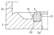
- the bottom surface (2d) of the recess (2c) of the body (2) has an annular inner protrusion (12) having a relatively small diameter and an annular shape having a relatively large diameter.
- the outer protrusion (13) is provided, and the synthetic resin sheet (5) is inserted between the inner protrusion (12) and the outer protrusion (13).
- the inner projecting portion (12) is caulked radially outward, and the outer projecting portion (13) is caulked radially inward, thereby preventing the synthetic resin sheet (5) from coming off.
- Patent Document 1 discloses that the inner protrusion is caulked to prevent the sheet from coming off.
- An object of the present invention is to provide a diaphragm valve with improved durability by performing proper caulking.
- a diaphragm valve includes a body provided with a fluid inflow passage, a fluid outflow passage, and an upwardly opened recess, an annular seat disposed on the bottom surface of the recess of the body, and pressed and separated by the seat. And an elastically deformable diaphragm that opens and closes the fluid passage, and an annular inner protrusion having a relatively small diameter and an annular outer protrusion having a relatively large diameter on the bottom surface of the body recess.
- the sheet is made of synthetic resin and is inserted between the inner projecting portion and the outer projecting portion, and the both projecting portions are caulked to prevent the sheet from coming off.
- the height of the inner protruding portion is made lower than the height of the outer protruding portion, and the outer corner of the inner protruding portion is a curved surface.
- the sheet is made of, for example, PCTFE (polychlorotrifluoroethylene), but may be made of other synthetic resin.
- the material of the body is made of steel such as 316L, but is not particularly limited.
- the caulking (plastic deformation) of each protruding portion is performed with an appropriate caulking jig.
- the caulking jig for the inner projecting part may have a different shape from the conventional one because the height of the inner projecting part is lower than the height of the outer projecting part (conventional inner projecting part). preferable.
- the configuration of the diaphragm valve other than the seat, the inner protruding portion, and the outer protruding portion is an appropriately known configuration.
- the actuator that presses and separates the diaphragm from the sheet may use compressed air, or may have another configuration.
- the diaphragm is made of, for example, a nickel alloy thin plate, but may be made of a stainless steel thin plate or a laminate of a stainless steel thin plate and a nickel / cobalt alloy thin plate.
- the height of the outer protrusion is made lower than the height of the seat so as not to interfere with the diaphragm.
- the height of the inner protrusion is normally equal to the height of the outer protrusion, but according to the diaphragm valve of the present invention, the height is lower than the height of the outer protrusion. It is preferable that (the height of the outer protruding portion ⁇ the height of the inner protruding portion) be 0.5 mm or more.
- the height of the inner protruding portion is lower than the height of the outer protruding portion, and the outer corner of the inner protruding portion is a curved surface, so that stress concentration on the sheet due to the inner protruding corner is relaxed, Proper caulking is possible, and the durability of the synthetic resin sheet is greatly improved.
- the preferable condition for improving the durability is 0.4 mm ⁇ the height of the inner protruding portion ⁇ 1.0 mm.
- a more preferable condition for improving the durability is 0.5 mm ⁇ the height of the inner protruding portion ⁇ 0.7 mm.
- the height of the inner projecting portion in the conventional diaphragm valve is about 1.5 mm. Based on this, the amount of deformation of the seat is simulated, and by setting the height of the inner projecting portion to 1 mm, it is about 31%. The amount of strain can be reduced. Moreover, the amount of distortion can be reduced by about 63% by setting the height of the inner protrusion to 0.4 mm.
- the height of the inner protrusion is 0.7 mm or less. If the height of the inner protrusion is too low, the sheet may come off, and the height of the inner protrusion is set to 0.4 mm or more, more preferably 0.5 mm or more, thereby reliably preventing the sheet from coming off. can do.
- the height of the inner projecting portion is made lower than the height of the outer projecting portion, and the outer corner of the inner projecting portion is a curved surface. Stress concentration is alleviated and proper caulking is possible, and the durability of the synthetic resin sheet is greatly improved.
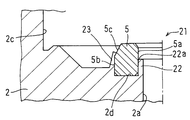
- FIG. 1 is an enlarged longitudinal sectional view showing a first embodiment of a diaphragm valve according to the present invention.
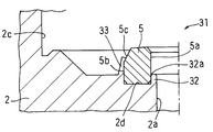
- FIG. 2 is an enlarged longitudinal sectional view showing a second embodiment of the diaphragm valve according to the present invention.
- FIG. 3 is a longitudinal sectional view showing a conventional diaphragm valve.
- FIG. 4 is an enlarged longitudinal sectional view of a main part of FIG.
- FIG. 1 shows a main part of a first embodiment of a diaphragm valve according to the present invention.
- this diaphragm valve (21) an annular inner protrusion (22) having a relatively small diameter and an annular outer protrusion having a relatively large diameter are formed on the bottom surface (2d) of the recess (2c) of the body (2).
- Part (23), the sheet (5) is made of synthetic resin and is inserted between the inner projecting part (22) and the outer projecting part (23), both projecting parts ( 22) (23) is caulked to prevent the sheet (5) from coming off.
- the sheet (5) is made of PCTFE (polychlorotrifluoroethylene).
- the material of the body (2) is stainless steel (for example, steel made of 316L).
- the sheet (5) is the same as the conventional one, and has an annular body with a substantially square cross section. More specifically, the inner peripheral surface (5a) is a cylindrical surface, and the outer peripheral surface is a cylindrical surface (5b) on the lower side and a tapered surface (5c) on the upper side.
- the height of the inner protrusion (22) and the height of the outer protrusion (23) are both higher than the height of the seat (5) so as not to interfere with the diaphragm (see (6) in FIG. 3). Has been lowered.
- the height of the inner protrusion (22) is usually equal to the height of the outer protrusion (23), but according to the diaphragm valve (21) of this embodiment, the height of the outer protrusion (23) is It is supposed to be lower than this.
- the height (upper end position) of the outer protrusion (23) is above the boundary between the cylindrical surface (5b) and the tapered surface (5c) on the outer peripheral surface of the seat (5).
- the outer corner (22a) of the inner protrusion (22) is a curved surface.
- the upper end position of the inner protrusion (22) is 1.0 mm from the bottom surface (2d) of the recess (2c), and the upper end position of the inner protrusion (22) The distance from the upper end position of the sheet (5) is 1.0 mm.
- the upper end position of the inner protrusion (12) is 1.5 mm from the bottom surface (2d) of the recess (2c), and the inner protrusion (12 ) And the upper end position of the sheet (5) are set to 0.5 mm.
- FIG. 2 shows a main part of a second embodiment of the diaphragm valve according to the present invention.
- this diaphragm valve (31) an annular inner protrusion (32) having a relatively small diameter and an annular outer protrusion having a relatively large diameter are formed on the bottom surface (2d) of the recess (2c) of the body (2).
- Part (33), the sheet (5) is made of synthetic resin, and is inserted between the inner protrusion (32) and the outer protrusion (33).
- 32) (33) is caulked to prevent the sheet (5) from coming off.
- the upper end position of the inner protrusion (32) is further lower than that of the diaphragm valve (21) of the first embodiment.
- the outer protrusion (33) is the same as that of the diaphragm valve (21) of the first embodiment, and the outer corner (32a) of the inner protrusion (32) is a curved surface.
- the upper end position of the inner protrusion (32) is 0.5 mm from the bottom surface (2d) of the recess (2c), and the upper end position of the inner protrusion (32) The distance from the upper end position of the sheet (5) is 1.5 mm.
- Table 1 shows the result of the simulation of the deformation amount (equivalent strain) of the sheet (5) when the upper end positions of the inner protrusions (12), (22), and (32) are changed.
- the upper end positions of the inner protrusions (12), (22), and (32) are the distances from the bottom surface (2d) of the recess (2c) of the body (2).
- the height of the inner protrusion (22) is 1.0 mm as in the first embodiment, compared to the conventional shape (height of the inner protrusion (12) is 1.5 mm).
- the outer corners (22a) and (32a) of the inner protrusions (22) and (32) are curved, so that it is possible to perform caulking that is more advantageous for durability, and durability of the synthetic resin sheet (5) Further improvement in sex is achieved.
- the shape of the curved surface various shapes are possible, from a curved surface having a small chamfering degree to a curved surface having a semicircular tip at the inner protruding portion.
- the preferable condition for improving the durability is that 0.4 mm ⁇ the height of the inner protrusions (22) and (32) (the bottom surface of the recess (2c) (in consideration of preventing the sheet (5) from coming off) The distance from 2d)) ⁇ 1.0 mm.
- a more preferable condition for improving the durability is 0.5 mm ⁇ the height of the inner protrusions (22) and (32) ⁇ 0.7 mm.
- the sheet (5) is made of a synthetic resin other than PCTFE (polychlorotrifluoroethylene), or the body (2) is made of a material other than steel made of 316L. it can.
Landscapes
- Engineering & Computer Science (AREA)
- General Engineering & Computer Science (AREA)
- Mechanical Engineering (AREA)
- Physics & Mathematics (AREA)
- Fluid Mechanics (AREA)
- Diaphragms And Bellows (AREA)
- Lift Valve (AREA)
- Fluid-Driven Valves (AREA)
- Valve Housings (AREA)
Abstract
Description

Claims (2)
- 流体流入通路、流体流出通路および上向きに開口した凹所が設けられたボディと、ボディの凹所の底面に配置された環状のシートと、シートに押圧・離間されることで流体通路の開閉を行う弾性変形可能なダイヤフラムとを備えており、ボディの凹所の底面に、環状で相対的に径が小さい内側突出部と環状で相対的に径が大きい外側突出部とが設けられており、シートは、合成樹脂製とされて、内側突出部と外側突出部との間に挿入されており、両突出部がかしめられることで、シートの抜けが防止されているダイヤフラム弁において、
内側突出部の高さが外側突出部の高さよりも低くなされるとともに、内側突出部の外側の角が曲面とされていることを特徴とするダイヤフラム弁。 - 0.4mm≦内側突出部の高さ≦1.0mmとされていることを特徴とする請求項1のダイヤフラム弁。
Priority Applications (3)
| Application Number | Priority Date | Filing Date | Title |
|---|---|---|---|
| KR1020157035669A KR101809810B1 (ko) | 2013-07-18 | 2014-07-04 | 다이어프램 밸브 |
| CN201480034016.2A CN105452741B (zh) | 2013-07-18 | 2014-07-04 | 隔膜阀 |
| US14/898,584 US9976658B2 (en) | 2013-07-18 | 2014-07-04 | Diaphragm valve |
Applications Claiming Priority (2)
| Application Number | Priority Date | Filing Date | Title |
|---|---|---|---|
| JP2013-149254 | 2013-07-18 | ||
| JP2013149254A JP6218470B2 (ja) | 2013-07-18 | 2013-07-18 | ダイヤフラム弁 |
Publications (1)
| Publication Number | Publication Date |
|---|---|
| WO2015008633A1 true WO2015008633A1 (ja) | 2015-01-22 |
Family
ID=52346102
Family Applications (1)
| Application Number | Title | Priority Date | Filing Date |
|---|---|---|---|
| PCT/JP2014/067870 Ceased WO2015008633A1 (ja) | 2013-07-18 | 2014-07-04 | ダイヤフラム弁 |
Country Status (6)
| Country | Link |
|---|---|
| US (1) | US9976658B2 (ja) |
| JP (1) | JP6218470B2 (ja) |
| KR (1) | KR101809810B1 (ja) |
| CN (1) | CN105452741B (ja) |
| TW (1) | TWI611130B (ja) |
| WO (1) | WO2015008633A1 (ja) |
Families Citing this family (4)
| Publication number | Priority date | Publication date | Assignee | Title |
|---|---|---|---|---|
| JP6654020B2 (ja) * | 2015-11-13 | 2020-02-26 | 株式会社フジキン | ダイヤフラムバルブおよびその製造方法 |
| KR102341512B1 (ko) * | 2016-08-25 | 2021-12-21 | 가부시키가이샤 깃츠 에스시티 | 다이아프램 밸브와 반도체 제조 장치용 유량 제어 기기 |
| CN112534166A (zh) | 2018-07-31 | 2021-03-19 | 株式会社富士金 | 阀装置 |
| KR102307625B1 (ko) * | 2020-05-08 | 2021-10-01 | 주식회사 유니락 | 로킹 밸브 |
Citations (4)
| Publication number | Priority date | Publication date | Assignee | Title |
|---|---|---|---|---|
| JPS639570U (ja) * | 1986-07-07 | 1988-01-22 | ||
| JPH0448470U (ja) * | 1990-08-29 | 1992-04-24 | ||
| JP2008304067A (ja) * | 1997-02-03 | 2008-12-18 | Swagelok Co | ダイヤフラム弁の弁座装置 |
| JP2012092861A (ja) * | 2010-10-25 | 2012-05-17 | Ckd Corp | 流体制御弁の弁座構造 |
Family Cites Families (10)
| Publication number | Priority date | Publication date | Assignee | Title |
|---|---|---|---|---|
| US5215286A (en) * | 1992-05-26 | 1993-06-01 | Nupro Company | High pressure diaphragm valve |
| JP3328896B2 (ja) * | 1995-02-01 | 2002-09-30 | 本田技研工業株式会社 | 無段変速機用プーリにおけるアクチュエータケースのかしめ構造 |
| JP3343313B2 (ja) | 1995-06-30 | 2002-11-11 | 株式会社フジキン | ダイヤフラム弁 |
| JP4587419B2 (ja) * | 2000-11-16 | 2010-11-24 | 株式会社フジキン | メタルダイヤフラム弁 |
| JP4085012B2 (ja) * | 2003-02-13 | 2008-04-30 | 忠弘 大見 | 真空排気系用バルブ |
| JP2006523810A (ja) * | 2003-04-14 | 2006-10-19 | スワゲロック カンパニー | ダイヤフラムバルブシート |
| TWM276133U (en) * | 2004-12-07 | 2005-09-21 | Metal Ind Res & Dev Ct | Pushing block applied in the valve |
| US8172197B2 (en) * | 2006-07-06 | 2012-05-08 | Mks Instruments, Inc. | Fast-acting pneumatic diaphragm valve |
| JP4355738B2 (ja) * | 2007-07-20 | 2009-11-04 | シーケーディ株式会社 | 流体制御弁 |
| JP5905456B2 (ja) * | 2010-06-22 | 2016-04-20 | スウエイジロク・カンパニー | 溶接されたダイヤフラムのための締付リング |
-
2013
- 2013-07-18 JP JP2013149254A patent/JP6218470B2/ja active Active
-
2014
- 2014-07-04 CN CN201480034016.2A patent/CN105452741B/zh not_active Expired - Fee Related
- 2014-07-04 WO PCT/JP2014/067870 patent/WO2015008633A1/ja not_active Ceased
- 2014-07-04 US US14/898,584 patent/US9976658B2/en active Active
- 2014-07-04 KR KR1020157035669A patent/KR101809810B1/ko active Active
- 2014-07-17 TW TW103124469A patent/TWI611130B/zh active
Patent Citations (4)
| Publication number | Priority date | Publication date | Assignee | Title |
|---|---|---|---|---|
| JPS639570U (ja) * | 1986-07-07 | 1988-01-22 | ||
| JPH0448470U (ja) * | 1990-08-29 | 1992-04-24 | ||
| JP2008304067A (ja) * | 1997-02-03 | 2008-12-18 | Swagelok Co | ダイヤフラム弁の弁座装置 |
| JP2012092861A (ja) * | 2010-10-25 | 2012-05-17 | Ckd Corp | 流体制御弁の弁座構造 |
Also Published As
| Publication number | Publication date |
|---|---|
| US9976658B2 (en) | 2018-05-22 |
| KR101809810B1 (ko) | 2017-12-15 |
| CN105452741B (zh) | 2018-04-27 |
| TWI611130B (zh) | 2018-01-11 |
| CN105452741A (zh) | 2016-03-30 |
| JP6218470B2 (ja) | 2017-10-25 |
| JP2015021543A (ja) | 2015-02-02 |
| TW201516299A (zh) | 2015-05-01 |
| KR20160009060A (ko) | 2016-01-25 |
| US20160131269A1 (en) | 2016-05-12 |
Similar Documents
| Publication | Publication Date | Title |
|---|---|---|
| JP5933370B2 (ja) | ダイヤフラム弁 | |
| JP6218470B2 (ja) | ダイヤフラム弁 | |
| US20150337868A1 (en) | Hydraulic damper | |
| JP2018524529A5 (ja) | ||
| WO2013084744A1 (ja) | ダイヤフラム弁 | |
| JP6376914B2 (ja) | 逆止弁構造 | |
| JP6530929B2 (ja) | 流体制御器 | |
| US10295074B2 (en) | Check valve | |
| US10323757B2 (en) | Diaphragm valve | |
| JP5371153B2 (ja) | 流体制御弁 | |
| TW201702508A (zh) | 隔膜閥 | |
| JP2019163896A5 (ja) | ||
| JP2016075233A5 (ja) | ||
| CN110573735B (zh) | 环状阀以及环状阀用阀芯 | |
| CN201827465U (zh) | 逆止阀 | |
| US20200386191A1 (en) | Check valve | |
| JP2010159790A (ja) | ダイヤフラム弁用ダイヤフラム押さえおよびこれを備えたダイヤフラム弁 | |
| JP2014047843A (ja) | ダイヤフラム弁 | |
| CN204692618U (zh) | 一种燃气比例阀的阀芯件 | |
| MX2021001740A (es) | Discos de valvula para usar con valvulas de fluido. | |
| CN207328266U (zh) | 一种方向盘的喇叭装置 | |
| JP2018025289A5 (ja) | ||
| JP2015113758A (ja) | ポペット弁およびバルブアセンブリ | |
| JP2017058112A5 (ja) | ||
| JP2016041965A (ja) | 電磁弁 |
Legal Events
| Date | Code | Title | Description |
|---|---|---|---|
| WWE | Wipo information: entry into national phase |
Ref document number: 201480034016.2 Country of ref document: CN |
|
| 121 | Ep: the epo has been informed by wipo that ep was designated in this application |
Ref document number: 14826420 Country of ref document: EP Kind code of ref document: A1 |
|
| WWE | Wipo information: entry into national phase |
Ref document number: 14898584 Country of ref document: US |
|
| ENP | Entry into the national phase |
Ref document number: 20157035669 Country of ref document: KR Kind code of ref document: A |
|
| NENP | Non-entry into the national phase |
Ref country code: DE |
|
| 122 | Ep: pct application non-entry in european phase |
Ref document number: 14826420 Country of ref document: EP Kind code of ref document: A1 |