WO2015005316A1 - ネットワーク装置及び通信制御方法 - Google Patents
ネットワーク装置及び通信制御方法 Download PDFInfo
- Publication number
- WO2015005316A1 WO2015005316A1 PCT/JP2014/068136 JP2014068136W WO2015005316A1 WO 2015005316 A1 WO2015005316 A1 WO 2015005316A1 JP 2014068136 W JP2014068136 W JP 2014068136W WO 2015005316 A1 WO2015005316 A1 WO 2015005316A1
- Authority
- WO
- WIPO (PCT)
- Prior art keywords
- discovery
- communication
- resource
- user terminal
- enb
- Prior art date
Links
Images


Classifications
-
- H—ELECTRICITY
- H04—ELECTRIC COMMUNICATION TECHNIQUE
- H04W—WIRELESS COMMUNICATION NETWORKS
- H04W72/00—Local resource management
- H04W72/50—Allocation or scheduling criteria for wireless resources
- H04W72/51—Allocation or scheduling criteria for wireless resources based on terminal or device properties
-
- H—ELECTRICITY
- H04—ELECTRIC COMMUNICATION TECHNIQUE
- H04W—WIRELESS COMMUNICATION NETWORKS
- H04W48/00—Access restriction; Network selection; Access point selection
- H04W48/08—Access restriction or access information delivery, e.g. discovery data delivery
- H04W48/14—Access restriction or access information delivery, e.g. discovery data delivery using user query or user detection
-
- H—ELECTRICITY
- H04—ELECTRIC COMMUNICATION TECHNIQUE
- H04W—WIRELESS COMMUNICATION NETWORKS
- H04W8/00—Network data management
- H04W8/005—Discovery of network devices, e.g. terminals
-
- H—ELECTRICITY
- H04—ELECTRIC COMMUNICATION TECHNIQUE
- H04W—WIRELESS COMMUNICATION NETWORKS
- H04W48/00—Access restriction; Network selection; Access point selection
- H04W48/16—Discovering, processing access restriction or access information
-
- H—ELECTRICITY
- H04—ELECTRIC COMMUNICATION TECHNIQUE
- H04W—WIRELESS COMMUNICATION NETWORKS
- H04W92/00—Interfaces specially adapted for wireless communication networks
- H04W92/16—Interfaces between hierarchically similar devices
- H04W92/18—Interfaces between hierarchically similar devices between terminal devices
Definitions
- the present invention relates to a network device and a communication control method used in a mobile communication system that supports D2D communication.
- D2D communication a plurality of neighboring user terminals perform direct inter-terminal communication without going through the network.
- cellular communication which is normal communication of a mobile communication system
- a user terminal performs communication via a network.
- the user terminal transmits and receives discovery signals used for discovery of nearby user terminals in order to perform D2D communication. After such a discovery process, the user terminal performs D2D communication with a nearby user terminal.
- D2D communication resource a radio resource used for transmission / reception of a discovery signal separately from a radio resource used for transmission / reception of user data in D2D communication.
- D2D communication resource a radio resource used for transmission / reception of user data in D2D communication
- securing the discovery resource can increase the probability of successful discovery of nearby user terminals, but the D2D communication resource or the cellular communication resource is relatively reduced, resulting in a decrease in system throughput. There is a problem.
- an object of the present invention is to provide a network device and a communication control method capable of appropriately setting discovery resources.
- the network device is included in the network of the mobile communication system in a mobile communication system that supports D2D communication that is direct inter-terminal communication.
- the network device includes a control unit configured to set a discovery resource that is a radio resource used for transmission / reception of a discovery signal for performing the D2D communication.
- the said control part controls the quantity of the said resource for a discovery based on the information regarding the user terminal located in the target area which is the setting target area of the said resource for a discovery.
- the communication control method is used in a mobile communication system that supports D2D communication that is direct inter-terminal communication.
- the communication control method includes a step in which a network device included in the network of the mobile communication system sets a discovery resource, which is a radio resource used for transmission / reception of a discovery signal for performing the D2D communication.
- the network device controls the amount of the discovery resource based on information related to user terminals located in a target area that is a setting target area of the discovery resource.
- the network device is included in the network of the mobile communication system in a mobile communication system that supports D2D communication that is direct inter-terminal communication.
- the network device includes a control unit configured to set a discovery resource that is a radio resource used for transmission / reception of a discovery signal for performing the D2D communication.
- the said control part controls the quantity of the said resource for a discovery based on the information regarding the user terminal located in the target area which is the setting target area of the said resource for a discovery.
- the target area is a cell of the mobile communication system.
- the control unit controls the amount of the discovery resource set in the cell based on information on the user terminal located in the cell.
- the information on the user terminal is information indicating the number of the user terminals existing in the target area.
- the information on the user terminal is information indicating the density of the user terminal located in the target area.
- the information on the user terminal is information indicating an attribute of the user terminal located in the target area.
- the information on the user terminal is information indicating the transmission power of the discovery signal in the user terminal located in the target area.
- the information on the user terminal is information on a result of discovery processing using the discovery signal in the user terminal located in the target area.
- the information on the user terminal is information indicating the size of the cell in which the user terminal is located.
- the communication control method is used in a mobile communication system that supports D2D communication that is direct communication between terminals.
- the communication control method includes a step in which a network device included in the network of the mobile communication system sets a discovery resource, which is a radio resource used for transmission / reception of a discovery signal for performing the D2D communication.
- the network device controls the amount of the discovery resource based on information related to user terminals located in a target area that is a setting target area of the discovery resource.
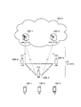
- FIG. 1 is a configuration diagram of an LTE system according to the embodiment.
- the LTE system according to the embodiment includes a UE (User Equipment) 100, an E-UTRAN (Evolved-UMTS Terrestrial Radio Access Network) 10, and an EPC (Evolved Packet Core) 20.
- UE User Equipment
- E-UTRAN Evolved-UMTS Terrestrial Radio Access Network
- EPC Evolved Packet Core
- the UE 100 corresponds to a user terminal.
- the UE 100 is a mobile communication device, and performs wireless communication with a connection destination cell (serving cell).
- the configuration of the UE 100 will be described later.
- the E-UTRAN 10 corresponds to a radio access network.
- the E-UTRAN 10 includes an eNB 200 (evolved Node-B).
- the eNB 200 corresponds to a base station.
- the eNB 200 is connected to each other via the X2 interface. The configuration of the eNB 200 will be described later.
- the eNB 200 manages one or a plurality of cells and performs radio communication with the UE 100 that has established a connection with the own cell.
- the eNB 200 has a radio resource management (RRM) function, a user data routing function, a measurement control function for mobility control / scheduling, and the like.
- RRM radio resource management
- Cell is used as a term indicating a minimum unit of a radio communication area, and is also used as a term indicating a function of performing radio communication with the UE 100.
- the EPC 20 corresponds to a core network.
- the LTE system network is configured by the E-UTRAN 10 and the EPC 20.
- the EPC 20 includes an MME (Mobility Management Entity) / S-GW (Serving-Gateway) 300.
- the MME performs various mobility controls for the UE 100.
- the S-GW controls user data transfer.
- the MME / S-GW 300 is connected to the eNB 200 via the S1 interface.
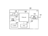
- FIG. 2 is a block diagram of the UE 100.
- the UE 100 includes a plurality of antennas 101, a radio transceiver 110, a user interface 120, a GNSS (Global Navigation Satellite System) receiver 130, a battery 140, a memory 150, and a processor 160.
- the memory 150 and the processor 160 constitute a control unit.
- the UE 100 may not have the GNSS receiver 130.
- the memory 150 may be integrated with the processor 160, and this set (that is, a chip set) may be used as the processor 160 '.
- the plurality of antennas 101 and the wireless transceiver 110 are used for transmitting and receiving wireless signals.
- the radio transceiver 110 converts the baseband signal (transmission signal) output from the processor 160 into a radio signal and transmits it from the plurality of antennas 101. Further, the radio transceiver 110 converts radio signals received by the plurality of antennas 101 into baseband signals (received signals) and outputs the baseband signals to the processor 160.
- the user interface 120 is an interface with a user who owns the UE 100, and includes, for example, a display, a microphone, a speaker, and various buttons.
- the user interface 120 receives an operation from the user and outputs a signal indicating the content of the operation to the processor 160.
- the GNSS receiver 130 receives a GNSS signal and outputs the received signal to the processor 160 in order to obtain location information indicating the geographical location of the UE 100.
- the battery 140 stores power to be supplied to each block of the UE 100.
- the memory 150 stores a program executed by the processor 160 and information used for processing by the processor 160.
- the processor 160 includes a baseband processor that modulates / demodulates and encodes / decodes a baseband signal, and a CPU (Central Processing Unit) that executes programs stored in the memory 150 and performs various processes. .
- the processor 160 may further include a codec that performs encoding / decoding of an audio / video signal.
- the processor 160 executes various processes and various communication protocols described later.
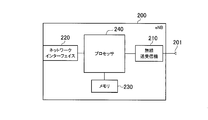
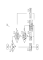
- FIG. 3 is a block diagram of the eNB 200.
- the eNB 200 includes a plurality of antennas 201, a radio transceiver 210, a network interface 220, a memory 230, and a processor 240.
- the memory 230 and the processor 240 constitute a control unit.
- the plurality of antennas 201 and the wireless transceiver 210 are used for transmitting and receiving wireless signals.
- the radio transceiver 210 converts a baseband signal (transmission signal) output from the processor 240 into a radio signal and transmits the radio signal from the plurality of antennas 201.
- the radio transceiver 210 converts radio signals received by the plurality of antennas 201 into baseband signals (reception signals) and outputs the baseband signals to the processor 240.
- the network interface 220 is connected to the neighboring eNB 200 via the X2 interface and is connected to the MME / S-GW 300 via the S1 interface.
- the network interface 220 is used for communication performed on the X2 interface and communication performed on the S1 interface.
- the memory 230 stores a program executed by the processor 240 and information used for processing by the processor 240.
- the processor 240 includes a baseband processor that performs modulation / demodulation and encoding / decoding of a baseband signal, and a CPU that executes a program stored in the memory 230 and performs various processes.
- the processor 240 executes various processes and various communication protocols described later.
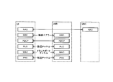
- FIG. 4 is a protocol stack diagram of a radio interface in the LTE system. As shown in FIG. 4, the radio interface protocol is divided into the first to third layers of the OSI reference model, and the first layer is a physical (PHY) layer.
- the second layer includes a MAC (Medium Access Control) layer, an RLC (Radio Link Control) layer, and a PDCP (Packet Data Convergence Protocol) layer.
- the third layer includes an RRC (Radio Resource Control) layer.
- the physical layer performs encoding / decoding, modulation / demodulation, antenna mapping / demapping, and resource mapping / demapping. Between the physical layer of UE100 and the physical layer of eNB200, user data and a control signal are transmitted via a physical channel.
- the MAC layer performs data priority control, retransmission processing by hybrid ARQ (HARQ), and the like. Between the MAC layer of the UE 100 and the MAC layer of the eNB 200, user data and control signals are transmitted via a transport channel.
- the MAC layer of the eNB 200 includes a scheduler that determines an uplink / downlink transport format (transport block size, modulation / coding scheme) and an allocation resource block to the UE 100.
- the RLC layer transmits data to the RLC layer on the receiving side using the functions of the MAC layer and the physical layer. Between the RLC layer of the UE 100 and the RLC layer of the eNB 200, user data and control signals are transmitted via a logical channel.
- the PDCP layer performs header compression / decompression and encryption / decryption.
- the RRC layer is defined only in the control plane that handles control signals. Control signals (RRC messages) for various settings are transmitted between the RRC layer of the UE 100 and the RRC layer of the eNB 200.
- the RRC layer controls the logical channel, the transport channel, and the physical channel according to establishment, re-establishment, and release of the radio bearer.
- RRC connection When there is a connection (RRC connection) between the RRC of the UE 100 and the RRC of the eNB 200, the UE 100 is in a connection state (RRC connection state). Otherwise, the UE 100 is in an idle state (RRC idle state).
- the NAS (Non-Access Stratum) layer located above the RRC layer performs session management and mobility management.
- FIG. 5 is a configuration diagram of a radio frame used in the LTE system.
- OFDMA Orthogonal Frequency Division Multiplexing Access
- SC-FDMA Single Carrier Frequency Multiple
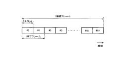
- the radio frame is composed of 10 subframes arranged in the time direction.
- Each subframe is composed of two slots arranged in the time direction.
- the length of each subframe is 1 ms, and the length of each slot is 0.5 ms.
- Each subframe includes a plurality of resource blocks (RB) in the frequency direction and includes a plurality of symbols in the time direction.
- Each resource block includes a plurality of subcarriers in the frequency direction.
- a resource element is composed of one subcarrier and one symbol.
- frequency resources are configured by resource blocks, and time resources are configured by subframes (or slots).
- the section of the first few symbols of each subframe is an area mainly used as a physical downlink control channel (PDCCH) for transmitting a control signal.
- the remaining part of each subframe is an area that can be used mainly as a physical downlink shared channel (PDSCH) for transmitting user data.
- PDCH physical downlink control channel
- PDSCH physical downlink shared channel
- both ends in the frequency direction in each subframe are regions used mainly as physical uplink control channels (PUCCH) for transmitting control signals.
- the remaining part of each subframe is an area that can be used mainly as a physical uplink shared channel (PUSCH) for transmitting user data.
- PUCCH physical uplink control channels
- D2D communication The LTE system according to the embodiment supports D2D communication that is direct terminal-to-terminal communication (UE-to-UE communication).
- UE-to-UE communication D2D communication will be described in comparison with cellular communication, which is normal communication of the LTE system.
- Cellular communication is a communication mode in which a data path passes through a network (E-UTRAN10, EPC20).
- a data path is a communication path for user data.
- D2D communication is a communication mode in which a data path set between UEs does not pass through a network.
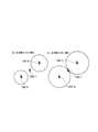
- FIG. 6 is a diagram for explaining D2D communication.
- the data path does not pass through the eNB 200.
- the UE 100-1 and the UE 100-2 that are close to each other directly perform radio communication with low transmission power in the cell of the eNB 200.
- the adjacent UE 100-1 and UE 100-2 perform radio communication directly with low transmission power, thereby reducing the power consumption of the UE 100 and reducing interference with adjacent cells compared to cellular communication. Can be reduced.
- the UE 100 transmits and receives a discovery signal used for discovery of a nearby UE 100 in order to perform D2D communication. After such a discovery process, the UE 100 performs D2D communication with a nearby UE 100.
- D2D communication resource used for at least transmission / reception of user data in D2D communication. Resources.
- the eNB 200 sets a discovery resource that is a radio resource used for transmission / reception of a discovery signal for performing D2D communication.
- the eNB 200 sets a resource for D2D communication and a resource for discovery in a time division manner in radio resources reserved for D2D communication.
- the eNB 200 may set the D2D communication resource and the discovery resource by frequency division. In the following, a case where the D2D communication resource and the discovery resource are set in a time division manner will be mainly described.
- the eNB 200 controls the amount (time length) of the discovery resource based on the information regarding the UE 100 located in the target area that is the setting target area of the discovery resource.
- the target area is, for example, a cell. However, the target area may be a tracking area. Alternatively, instead of controlling the amount of discovery resource for each area, the amount of discovery resource for each UE 100 may be controlled. In addition, being in the service area does not matter whether the UE 100 is in an idle state (RRC idle state) or in a connected state (RRC connected state).
- the eNB 200 adapts the amount of the discovery resource according to the situation of the UE 100 located in the target area by controlling the amount of the discovery resource based on the information regarding the UE 100 located in the target area. Can be set automatically. Therefore, the discovery resource can be set appropriately.
- operation patterns 1 to 7 As operations for controlling the amount of discovery resources, there are operation patterns 1 to 7 shown below. Although details of the operation patterns 1 to 7 will be described later, an outline of each operation pattern will be described here. Note that the operation patterns 1 to 7 are not limited to being implemented separately and can be implemented by combining two or more patterns.
- the eNB 200 controls the amount of discovery resources based on information indicating the number of UEs 100 located in the target area.
- the eNB 200 controls the amount of the discovery resource based on the information indicating the transmission power of the discovery signal in the UE 100 located in the target area.
- the eNB 200 controls the amount of discovery resources based on information indicating the density of the UEs 100 located in the target area.
- the eNB 200 controls the amount of discovery resources based on information related to the result of discovery processing using discovery signals in the UE 100 located in the target area.
- the eNB 200 controls the amount of discovery resources based on information indicating the size of the cell where the UE 100 is located.
- the eNB 200 controls the amount of discovery resources based on information indicating the attributes of the UE 100 located in the target area. In the operation pattern 7, the eNB 200 controls the amount of discovery resources based on information indicating the frequency band used by the UE 100 located in the target area to transmit and receive discovery signals.
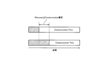
- FIG. 7 is a diagram for explaining a discovery resource format according to the embodiment.
- D2D communication resources and discovery resources are set in a time division manner in subframes reserved for D2D communication.
- the resource for D2D communication is a radio resource used for transmission / reception of user data (and control signals) in D2D communication.
- the discovery resource is a radio resource used for transmission / reception of a discovery signal. For example, code division multiplexing using orthogonal codes is applied to the discovery resource.
- the section of several symbols from the head corresponds to the discovery resource, and the remaining section corresponds to the D2D communication resource.
- a section corresponding to the discovery resource is referred to as “discovery time”, and a section corresponding to the D2D communication resource is referred to as “D2D communication time”.
- the total time length of the discovery time and the D2D communication time is a certain time length (subframe length in the example of FIG. 7). Therefore, if the discovery time is extended, the D2D communication time is relatively shortened, and the D2D communication capacity (D2D communication throughput) decreases. On the other hand, when the discovery time is shortened, the D2D communication time is relatively extended, and the D2D communication capacity (D2D communication throughput) is improved.
- the discovery resource and the D2D communication resource are set in a time-sharing manner in units of symbols in the subframe. Time division may be set for each subframe.
- UE 100 receives allocation of discovery resources (time / frequency resources) and orthogonal codes from eNB 200 in order to transmit and receive discovery signals.
- UE100 transmits / receives the discovery signal using the discovery resource and orthogonal code allocated from eNB200.
- Operation pattern 1 In the operation pattern 1, the eNB 200 controls the discovery time based on information indicating the number of UEs 100 located in the target area.
- the information indicating the number of UEs 100 is, for example, the number of UEs 100 connected in the own cell or the number of UEs 100 idle in the tracking area including the own cell.
- the eNB 200 can acquire the number of idle UEs 100 from the MME 300. Further, the number of UEs 100 may be limited to the number of UEs 100 that support D2D communication. In this case, the eNB 200 acquires information indicating whether or not D2D communication is supported from the UE 100.
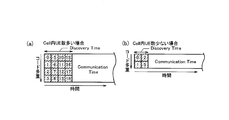
- FIG. 8 is a diagram for explaining the operation pattern 1.
- the eNB 200 extends the discovery time when the number of UEs 100 is large, and shortens the discovery time when the number of UEs 100 is small. By controlling the discovery time in accordance with the number of UEs 100, an amount of discovery resources suitable for the number of UEs 100 can be set.
- the discovery time is extended and the code length is extended. Since the number of available orthogonal codes can be increased by extending the code length, it is possible to assign orthogonal codes for discovery signals to more UEs 100.
- the code length of the orthogonal code applied to the discovery time is fixed, the number of available orthogonal codes is fixed, so that the discovery time is extended to accommodate the discovery time. Increase the number of possible UEs.
- the discovery time By extending the discovery time to n times the time length (unit time length) corresponding to one orthogonal code, the number of UEs that can be accommodated in the discovery time can be increased to n times.
- D2D communication time is extended
- frequency resources in the discovery time may be reduced.
- the number of UEs 100 is small, not all resource blocks are used as discovery resources and D2D communication resources in a subframe reserved for D2D communication, but only some resource blocks are used. Used as discovery resource and D2D communication resource.
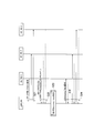
- FIG. 9 is a sequence diagram of the operation pattern 1.
- the eNB 200 calculates a discovery time based on the number of UEs 100 in the own cell. The calculation flow of the discovery time will be described later.
- the eNB 200 notifies the calculated discovery time to the UE 100 in the own cell by unicast or broadcast. The UE 100 may transmit a response to the notified discovery time to the eNB 200 (step S13).
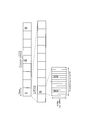
- FIG. 10 is a flowchart showing a calculation flow of discovery time in the operation pattern 1.
- the eNB 200 determines whether or not the UE 100 exists in the own cell. If “No” in step S111, the eNB 200 sets the discovery time to zero in step S112. In the case of “Yes” in Step S111, in Step S113, the eNB 200 determines whether or not the number of UEs 100 in the own cell is equal to or greater than the maximum number of UEs that can be accommodated in the discovery time. In the case of “Yes” in step S113, in step S114, the eNB 200 sets the discovery time to the maximum value.
- Step S115 the eNB 200 determines whether or not the number of UEs 100 in the own cell exceeds the maximum number of UEs that can be code division multiplexed. In the case of “Yes” in Step S115, in Step S117, the eNB 200 sets a value (rounded up) obtained by dividing the number of UEs 100 in the own cell by the maximum number of UEs that can be accommodated with the minimum discovery time as the discovery time Set. If “No” in step S115, in step S116, the eNB 200 sets a value obtained by doubling the minimum discovery time as the discovery time.
- the eNB 200 controls the amount of the discovery resource based on the information indicating the transmission power of the discovery signal in the UE 100 located in the target area.
- the eNB 200 can use the managed transmission power information of the discovery signal.
- the eNB 200 acquires information indicating the transmission power of the discovery signal from the UE 100 and uses it.
- the information indicating the transmission power of the discovery signal may be a statistic (average value, maximum value, minimum value, mode value, etc.) of the transmission power of the discovery signal in the UE 100 in the own cell.
- FIG. 11 is a diagram for explaining the operation pattern 2.
- the eNB 200 extends the discovery time when the discovery signal transmission power is low, and shortens the discovery time when the discovery signal transmission power is large.
- the smaller the transmission power of the discovery signal the narrower the reach of the discovery signal, so the probability of successful discovery processing is reduced.
- the longer the discovery time the higher the probability of successful discovery processing. Therefore, when the transmission power of the discovery signal is small, the probability of successful discovery processing can be maintained at a certain level by extending the discovery time.
- the sequence for notifying the UE 100 of the discovery time determined by the eNB 200 is the same as the operation pattern 1.
- the eNB 200 controls the amount of discovery resources based on information indicating the density of the UEs 100 located in the target area.
- the information indicating the density of the UE 100 is, for example, a UE-UE path loss or a UE-UE distance based on the UE location information.
- Each UE 100 transmits a reference signal whose transmission power is known, and a difference between reception power and transmission power at the time of reception of the reference signal in each UE 100 can be acquired and used from each UE 100 as a UE-UE path loss.
- eNB200 can utilize the GNSS positional information acquired from UE100 as UE positional information.
- the eNB 200 extends the discovery time when the density of the UE 100 in the own cell is low, and shortens the discovery time when the density of the UE 100 in the own cell is high.
- the lower the density of the UE 100 the lower the probability of successful discovery processing.
- the longer the discovery time the higher the probability of successful discovery processing. Therefore, when the density of the UE 100 is low, the probability of successful discovery processing can be maintained at a certain level by extending the discovery time.
- the discovery time is extended when the density of the UE 100 in the own cell is high, and for discovery when the density of the UE 100 in the own cell is low. Time may be shortened.
- FIG. 12 is a sequence diagram of the operation pattern 3.
- the eNB 200 requests the UE 100 (UE 100-1 to UE 100-3) in the own cell for a UE-UE path loss.
- each of the UE 100-1 to UE 100-3 transmits a UE-UE path loss list to the eNB 200.
- the eNB 200 determines a discovery time for each of the UE 100-1 to UE 100-3 based on the list of UE-UE path loss. The flow for determining the discovery time will be described later.
- the eNB 200 notifies the UE 100-1 to UE 100-3 of the determined discovery time by unicast.
- the UE 100-1 to the UE 100-3 may transmit a response to the notified discovery time to the eNB 200.
- FIG. 13 is a flowchart showing a calculation flow of the discovery time in the operation pattern 3. As shown in FIG. 13, the procedures of steps S231 to S234 are performed for each UE 100.
- the eNB 200 determines whether the number of UEs that can be discovered in the minimum discovery time is equal to or greater than the minimum number of discovered UEs based on the list of UE-UE path loss acquired from the target UE 100. For example, when the value obtained by subtracting the UE-UE path loss from the transmission power of the discovery signal (that is, the assumed reception power of the discovery signal) is equal to or greater than a threshold, the neighboring UE 100 corresponding to the UE-UE path loss. It can be determined that can be found.
- step S231 a loop for determining the discovery time is started, and if the discovery time is less than the maximum discovery time (step S232: No), the unit discovery time is added to the discovery time. Are added (step S233), and when the number of UEs that can be discovered in the discovery time exceeds the minimum number of discovered UEs, the loop is exited and the discovery time is saved (step S234).
- the eNB 200 controls the amount of discovery resources based on information related to the result of discovery processing using discovery signals in the UE 100 located in the target area. For example, by reporting the result of the discovery process from the UE 100 to the eNB 200, the eNB 200 can use information regarding the result of the discovery process.
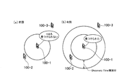
- FIG. 14 is a diagram for explaining the operation pattern 4.
- the eNB 200 extends the current discovery time when the UE 100 cannot find a neighboring UE in the past discovery process, and the UE 100 can discover the neighboring UE in the past discovery process. Reduce the current discovery time.
- a target value for the number of neighboring UEs discovered in the discovery process may be set, and the discovery time may be adjusted so as to be the target value. For example, it is possible to adopt a method of extending the discovery time until the minimum number of discovered UEs is reached, and shortening the discovery time until the number of discovered UEs is less than the maximum.
- the eNB 200 controls the amount of discovery resources based on information indicating the size of the cell where the UE 100 is located.
- the information indicating the cell size may be a cell type (macro cell, pico cell, femto cell), or may be information indicating the cell radius, diameter, or transmission power.
- the eNB 200 extends the discovery time so that the reachable range of the discovery time is expanded as the size of the own cell is larger.
- the eNB 200 shortens the discovery time so that the reachable range of the discovery time is reduced as the size of the own cell is smaller.
- Operation pattern 6 the eNB 200 controls the amount of discovery resources based on information indicating the attributes of the UE 100 located in the target area.
- the attribute of the UE 100 is a contract condition (for example, a contract such as “discover up to 10 m or discover up to 20 m”, “discover up to 10 UE, discover up to 20 UE”) regarding the discovery process.
- the attribute of the UE 100 may be a type of the UE 100 (for example, Public Safety UE, normal UE).
- the eNB 200 can acquire and use information indicating the attributes of the UE 100 from the UE 100.
- the eNB 200 adjusts the discovery time so that the UE 100 having the contract condition regarding the discovery process satisfies the contract condition. Further, the eNB 200 extends the discovery time for the public safety UE so as to increase the success rate of the discovery process compared to the normal UE.
- the reachable range of discovery signals required for each type of UE is different.
- discovery signals to which orthogonal codes having different code lengths are mixed without dividing resources in the same cell, an interference factor is caused.
- the code length of the orthogonal code applied to the discovery signal is set to the same length, the discovery time is extended, and the number of repetitions in the repeated transmission of the discovery signal according to the type of UE change. Further, the reception time length of the discovery time is determined according to the type of UE. Thereby, the discovery range requested
- Operation pattern 7 In the operation pattern 7, the eNB 200 controls the amount of discovery resources based on information indicating the frequency band used by the UE 100 located in the target area to transmit and receive discovery signals.
- the eNB 200 can use information indicating the defined frequency band.
- the eNB 200 reports the frequency band used for transmission / reception of discovery signals from the UE 100 to the eNB 200, whereby the eNB 200 allows the UE 100 to transmit / receive discovery signals.
- Information indicating the frequency band to be used can be used.
- the eNB 200 shortens the discovery time when the frequency band used for transmission / reception of the discovery signal is low. On the other hand, when the frequency band used for transmission / reception of the discovery signal is high, the eNB 200 extends the discovery time.
- the eNB 200 controls the discovery time based on information regarding the UE 100 located in the target area. Thereby, the discovery time can be adaptively set according to the situation of the UE 100 located in the target area. Therefore, the discovery time can be set appropriately.
- the eNB 200 has been described as a specific example of the network device according to the present invention.
- the network device according to the present invention is not limited to the eNB 200, and may be a higher-level device (MME 300 or OAM) of the eNB 200.
- FIG. 15 is a diagram for explaining interference between UEs having different discovery time settings.
- the discovery time overlaps (collises) with a part of the D2D communication time in another UE with a short discovery time. This overlapping portion is difficult to decode on the receiving side. Therefore, the eNB 200 (or UE 100) that has detected such interference due to duplication may employ any of the following interference avoidance measures.
- the first method is a method of changing the transmission power of each UE that gives interference.
- priority may be given to the discovery signal (discovery time), and user data (D2D communication time) may be prioritized.
- the second method is a method of shifting the transmission timing or use frequency of each UE that gives interference.
- the third method is a method of increasing the number of times the discovery time is repeatedly transmitted in order to make the discovery signal (discovery time) have interference resistance.
- FIG. 16 is a diagram for explaining another format of the discovery resource.
- the discovery resource is provided in a specific resource block in a specific communication frequency band in the frequency direction. Further, the discovery resource is provided in a specific symbol in a specific subframe in the time direction.
- the LTE system has been described as an example of a cellular communication system.
- the present invention is not limited to the LTE system, and the present invention may be applied to systems other than the LTE system.
- the present invention is useful in the mobile communication field.
Abstract
eNB200は、D2D通信を行うための発見用信号の送受信に使用される無線リソースである発見用リソースを設定する。eNB200は、発見用リソースの設定対象のエリアである対象エリアに在圏するUE100に関する情報に基づいて、発見用リソースの量(時間長)を制御する。
Description
本発明は、D2D通信をサポートする移動通信システムにおいて用いられるネットワーク装置及び通信制御方法に関する。
移動通信システムの標準化プロジェクトである3GPP(3rd Generation Partnership Project)では、リリース12以降の新機能として、端末間(Device to Device:D2D)通信の導入が検討されている(非特許文献1参照)。
D2D通信では、近接する複数のユーザ端末がネットワークを経由せずに直接的な端末間通信を行う。一方、移動通信システムの通常の通信であるセルラ通信では、ユーザ端末がネットワークを経由して通信を行う。
ユーザ端末は、D2D通信を行うために、近傍のユーザ端末の発見に使用される発見用信号を送受信する。このような発見処理の後、ユーザ端末は、近傍のユーザ端末とのD2D通信を行う。
3GPP技術報告書 「TR 22.803 V12.1.0」 2013年3月
D2D通信をサポートする移動通信システムでは、D2D通信におけるユーザデータの送受信に使用される無線リソース(以下、「D2D通信用リソース」という。)とは別に、発見用信号の送受信に使用される無線リソース(以下、「発見用リソース」という。)を確保する必要があると考えられる。
しかしながら、発見用リソースを確保することにより、近傍のユーザ端末の発見に成功する確率を高めることができるものの、D2D通信用リソース又はセルラ通信用リソースが相対的に減少するため、システムスループットが低下するという問題がある。
そこで、本発明は、発見用リソースを適切に設定可能なネットワーク装置及び通信制御方法を提供することを目的とする。
第1の特徴に係るネットワーク装置は、直接的な端末間通信であるD2D通信をサポートする移動通信システムにおいて、前記移動通信システムのネットワークに含まれる。前記ネットワーク装置は、前記D2D通信を行うための発見用信号の送受信に使用される無線リソースである発見用リソースを設定する制御部を備える。前記制御部は、前記発見用リソースの設定対象のエリアである対象エリアに在圏するユーザ端末に関する情報に基づいて、前記発見用リソースの量を制御する。
第2の特徴に係る通信制御方法は、直接的な端末間通信であるD2D通信をサポートする移動通信システムにおいて用いられる。前記通信制御方法は、前記移動通信システムのネットワークに含まれるネットワーク装置が、前記D2D通信を行うための発見用信号の送受信に使用される無線リソースである発見用リソースを設定するステップを備える。前記設定するステップにおいて、前記ネットワーク装置は、前記発見用リソースの設定対象のエリアである対象エリアに在圏するユーザ端末に関する情報に基づいて、前記発見用リソースの量を制御する。
[実施形態の概要]
実施形態に係るネットワーク装置は、直接的な端末間通信であるD2D通信をサポートする移動通信システムにおいて、前記移動通信システムのネットワークに含まれる。前記ネットワーク装置は、前記D2D通信を行うための発見用信号の送受信に使用される無線リソースである発見用リソースを設定する制御部を備える。前記制御部は、前記発見用リソースの設定対象のエリアである対象エリアに在圏するユーザ端末に関する情報に基づいて、前記発見用リソースの量を制御する。
実施形態に係るネットワーク装置は、直接的な端末間通信であるD2D通信をサポートする移動通信システムにおいて、前記移動通信システムのネットワークに含まれる。前記ネットワーク装置は、前記D2D通信を行うための発見用信号の送受信に使用される無線リソースである発見用リソースを設定する制御部を備える。前記制御部は、前記発見用リソースの設定対象のエリアである対象エリアに在圏するユーザ端末に関する情報に基づいて、前記発見用リソースの量を制御する。
実施形態では、前記対象エリアは、前記移動通信システムのセルである。前記制御部は、前記セルに在圏する前記ユーザ端末に関する情報に基づいて、前記セルに設定する前記発見用リソースの量を制御する。
実施形態では、前記ユーザ端末に関する情報とは、前記対象エリアに在圏する前記ユーザ端末の数を示す情報である。
実施形態では、前記ユーザ端末に関する情報とは、前記対象エリアに在圏する前記ユーザ端末の密度を示す情報である。
実施形態では、前記ユーザ端末に関する情報とは、前記対象エリアに在圏する前記ユーザ端末の属性を示す情報である。
実施形態では、前記ユーザ端末に関する情報とは、前記対象エリアに在圏する前記ユーザ端末における前記発見用信号の送信電力を示す情報である。
実施形態では、前記ユーザ端末に関する情報とは、前記対象エリアに在圏する前記ユーザ端末における前記発見用信号を用いた発見処理の結果に関する情報である。
実施形態では、前記ユーザ端末に関する情報とは、前記ユーザ端末が在圏する前記セルのサイズを示す情報である。
実施形態に係る通信制御方法は、直接的な端末間通信であるD2D通信をサポートする移動通信システムにおいて用いられる。前記通信制御方法は、前記移動通信システムのネットワークに含まれるネットワーク装置が、前記D2D通信を行うための発見用信号の送受信に使用される無線リソースである発見用リソースを設定するステップを備える。前記設定するステップにおいて、前記ネットワーク装置は、前記発見用リソースの設定対象のエリアである対象エリアに在圏するユーザ端末に関する情報に基づいて、前記発見用リソースの量を制御する。
[実施形態]
以下において、本発明をLTEシステムに適用する場合の実施形態を説明する。
以下において、本発明をLTEシステムに適用する場合の実施形態を説明する。
(システム構成)
図1は、実施形態に係るLTEシステムの構成図である。図1に示すように、実施形態に係るLTEシステムは、UE(User Equipment)100、E-UTRAN(Evolved-UMTS Terrestrial Radio Access Network)10、及びEPC(Evolved Packet Core)20を備える。
図1は、実施形態に係るLTEシステムの構成図である。図1に示すように、実施形態に係るLTEシステムは、UE(User Equipment)100、E-UTRAN(Evolved-UMTS Terrestrial Radio Access Network)10、及びEPC(Evolved Packet Core)20を備える。
UE100は、ユーザ端末に相当する。UE100は、移動型の通信装置であり、接続先のセル(サービングセル)との無線通信を行う。UE100の構成については後述する。
E-UTRAN10は、無線アクセスネットワークに相当する。E-UTRAN10は、eNB200(evolved Node-B)を含む。eNB200は、基地局に相当する。eNB200は、X2インターフェイスを介して相互に接続される。eNB200の構成については後述する。
eNB200は、1又は複数のセルを管理しており、自セルとの接続を確立したUE100との無線通信を行う。eNB200は、無線リソース管理(RRM)機能、ユーザデータのルーティング機能、モビリティ制御・スケジューリングのための測定制御機能などを有する。「セル」は、無線通信エリアの最小単位を示す用語として使用される他に、UE100との無線通信を行う機能を示す用語としても使用される。
EPC20は、コアネットワークに相当する。E-UTRAN10及びEPC20によりLTEシステムのネットワークが構成される。EPC20は、MME(Mobility Management Entity)/S-GW(Serving-Gateway)300を含む。MMEは、UE100に対する各種モビリティ制御などを行う。S-GWは、ユーザデータの転送制御を行う。MME/S-GW300は、S1インターフェイスを介してeNB200と接続される。
図2は、UE100のブロック図である。図2に示すように、UE100は、複数のアンテナ101、無線送受信機110、ユーザインターフェイス120、GNSS(Global Navigation Satellite System)受信機130、バッテリ140、メモリ150、及びプロセッサ160を備える。メモリ150及びプロセッサ160は、制御部を構成する。UE100は、GNSS受信機130を有していなくてもよい。また、メモリ150をプロセッサ160と一体化し、このセット(すなわち、チップセット)をプロセッサ160’としてもよい。
複数のアンテナ101及び無線送受信機110は、無線信号の送受信に用いられる。無線送受信機110は、プロセッサ160が出力するベースバンド信号(送信信号)を無線信号に変換して複数のアンテナ101から送信する。また、無線送受信機110は、複数のアンテナ101が受信する無線信号をベースバンド信号(受信信号)に変換してプロセッサ160に出力する。
ユーザインターフェイス120は、UE100を所持するユーザとのインターフェイスであり、例えば、ディスプレイ、マイク、スピーカ、及び各種ボタンなどを含む。ユーザインターフェイス120は、ユーザからの操作を受け付けて、該操作の内容を示す信号をプロセッサ160に出力する。GNSS受信機130は、UE100の地理的な位置を示す位置情報を得るために、GNSS信号を受信して、受信した信号をプロセッサ160に出力する。バッテリ140は、UE100の各ブロックに供給すべき電力を蓄える。
メモリ150は、プロセッサ160により実行されるプログラム、及びプロセッサ160による処理に使用される情報を記憶する。プロセッサ160は、ベースバンド信号の変調・復調及び符号化・復号などを行うベースバンドプロセッサと、メモリ150に記憶されるプログラムを実行して各種の処理を行うCPU(Central Processing Unit)と、を含む。プロセッサ160は、さらに、音声・映像信号の符号化・復号を行うコーデックを含んでもよい。プロセッサ160は、後述する各種の処理及び各種の通信プロトコルを実行する。
図3は、eNB200のブロック図である。図3に示すように、eNB200は、複数のアンテナ201、無線送受信機210、ネットワークインターフェイス220、メモリ230、及びプロセッサ240を備える。メモリ230及びプロセッサ240は、制御部を構成する。
複数のアンテナ201及び無線送受信機210は、無線信号の送受信に用いられる。無線送受信機210は、プロセッサ240が出力するベースバンド信号(送信信号)を無線信号に変換して複数のアンテナ201から送信する。また、無線送受信機210は、複数のアンテナ201が受信する無線信号をベースバンド信号(受信信号)に変換してプロセッサ240に出力する。
ネットワークインターフェイス220は、X2インターフェイスを介して隣接eNB200と接続され、S1インターフェイスを介してMME/S-GW300と接続される。ネットワークインターフェイス220は、X2インターフェイス上で行う通信及びS1インターフェイス上で行う通信に用いられる。
メモリ230は、プロセッサ240により実行されるプログラム、及びプロセッサ240による処理に使用される情報を記憶する。プロセッサ240は、ベースバンド信号の変調・復調及び符号化・復号などを行うベースバンドプロセッサと、メモリ230に記憶されるプログラムを実行して各種の処理を行うCPUと、を含む。プロセッサ240は、後述する各種の処理及び各種の通信プロトコルを実行する。
図4は、LTEシステムにおける無線インターフェイスのプロトコルスタック図である。図4に示すように、無線インターフェイスプロトコルは、OSI参照モデルの第1層乃至第3層に区分されており、第1層は物理(PHY)層である。第2層は、MAC(Medium Access Control)層、RLC(Radio Link Control)層、及びPDCP(Packet Data Convergence Protocol)層を含む。第3層は、RRC(Radio Resource Control)層を含む。
物理層は、符号化・復号、変調・復調、アンテナマッピング・デマッピング、及びリソースマッピング・デマッピングを行う。UE100の物理層とeNB200の物理層との間では、物理チャネルを介してユーザデータ及び制御信号が伝送される。
MAC層は、データの優先制御、及びハイブリッドARQ(HARQ)による再送処理などを行う。UE100のMAC層とeNB200のMAC層との間では、トランスポートチャネルを介してユーザデータ及び制御信号が伝送される。eNB200のMAC層は、上下リンクのトランスポートフォーマット(トランスポートブロックサイズ、変調・符号化方式)及びUE100への割当リソースブロックを決定するスケジューラを含む。
RLC層は、MAC層及び物理層の機能を利用してデータを受信側のRLC層に伝送する。UE100のRLC層とeNB200のRLC層との間では、論理チャネルを介してユーザデータ及び制御信号が伝送される。
PDCP層は、ヘッダ圧縮・伸張、及び暗号化・復号化を行う。
RRC層は、制御信号を取り扱う制御プレーンでのみ定義される。UE100のRRC層とeNB200のRRC層との間では、各種設定のための制御信号(RRCメッセージ)が伝送される。RRC層は、無線ベアラの確立、再確立及び解放に応じて、論理チャネル、トランスポートチャネル、及び物理チャネルを制御する。UE100のRRCとeNB200のRRCとの間に接続(RRC接続)がある場合、UE100は接続状態(RRC接続状態)であり、そうでない場合、UE100はアイドル状態(RRCアイドル状態)である。
RRC層の上位に位置するNAS(Non-Access Stratum)層は、セッション管理及びモビリティ管理などを行う。
図5は、LTEシステムで使用される無線フレームの構成図である。LTEシステムは、下りリンク(DL)にはOFDMA(Orthogonal Frequency Division Multiplexing Access)、上りリンク(UL)にはSC-FDMA(Single Carrier Frequency Division Multiple Access)がそれぞれ適用される。
図5に示すように、無線フレームは、時間方向に並ぶ10個のサブフレームで構成される。各サブフレームは、時間方向に並ぶ2個のスロットで構成される。各サブフレームの長さは1msであり、各スロットの長さは0.5msである。各サブフレームは、周波数方向に複数個のリソースブロック(RB)を含み、時間方向に複数個のシンボルを含む。各リソースブロックは、周波数方向に複数個のサブキャリアを含む。1つのサブキャリア及び1つのシンボルによりリソースエレメントが構成される。
UE100に割り当てられる無線リソースのうち、周波数リソースはリソースブロックにより構成され、時間リソースはサブフレーム(又はスロット)により構成される。
DLにおいて、各サブフレームの先頭数シンボルの区間は、主に制御信号を伝送するための物理下りリンク制御チャネル(PDCCH)として使用される領域である。また、各サブフレームの残りの部分は、主にユーザデータを伝送するための物理下りリンク共有チャネル(PDSCH)として使用できる領域である。
ULにおいて、各サブフレームにおける周波数方向の両端部は、主に制御信号を伝送するための物理上りリンク制御チャネル(PUCCH)として使用される領域である。各サブフレームにおける残りの部分は、主にユーザデータを伝送するための物理上りリンク共有チャネル(PUSCH)として使用できる領域である。
(D2D通信)
実施形態に係るLTEシステムは、直接的な端末間通信(UE間通信)であるD2D通信をサポートする。ここでは、D2D通信を、LTEシステムの通常の通信であるセルラ通信と比較して説明する。セルラ通信は、データパスがネットワーク(E-UTRAN10、EPC20)を経由する通信モードである。データパスとは、ユーザデータの通信経路である。これに対し、D2D通信は、UE間に設定されるデータパスがネットワークを経由しない通信モードである。
実施形態に係るLTEシステムは、直接的な端末間通信(UE間通信)であるD2D通信をサポートする。ここでは、D2D通信を、LTEシステムの通常の通信であるセルラ通信と比較して説明する。セルラ通信は、データパスがネットワーク(E-UTRAN10、EPC20)を経由する通信モードである。データパスとは、ユーザデータの通信経路である。これに対し、D2D通信は、UE間に設定されるデータパスがネットワークを経由しない通信モードである。
図6は、D2D通信を説明するための図である。図6に示すように、D2D通信は、データパスがeNB200を経由しない。相互に近接するUE100-1及びUE100-2は、eNB200のセルにおいて、低送信電力で直接的に無線通信を行う。このように、近接するUE100-1及びUE100-2が低送信電力で直接的に無線通信を行うことにより、セルラ通信と比べて、UE100の消費電力を削減し、かつ、隣接セルへの干渉を低減できる。
(実施形態に係る動作)
以下、実施形態に係る動作について説明する。
以下、実施形態に係る動作について説明する。
(1)動作概要
UE100は、D2D通信を行うために、近傍のUE100の発見に使用される発見用信号を送受信する。このような発見処理の後、UE100は、近傍のUE100とのD2D通信を行う。
UE100は、D2D通信を行うために、近傍のUE100の発見に使用される発見用信号を送受信する。このような発見処理の後、UE100は、近傍のUE100とのD2D通信を行う。
よって、D2D通信をサポートする移動通信システムでは、D2D通信において少なくともユーザデータの送受信に使用される無線リソース(D2D通信用リソース)とは別に、発見用信号の送受信に使用される無線リソース(発見用リソース)を確保する必要がある。しかしながら、発見用リソースを確保することにより、近傍のUE100の発見に成功する確率を高めることができるものの、D2D通信用リソース又はセルラ通信用リソースが相対的に減少するため、システムスループットが低下する。
実施形態では、eNB200は、D2D通信を行うための発見用信号の送受信に使用される無線リソースである発見用リソースを設定する。eNB200は、例えば、D2D通信のために確保される無線リソースにおいて、D2D通信用リソース及び発見用リソースを時分割で設定する。或いは、eNB200は、D2D通信用リソース及び発見用リソースを周波数分割で設定してもよい。以下においては、D2D通信用リソース及び発見用リソースを時分割で設定するケースを主として説明する。
eNB200は、発見用リソースの設定対象のエリアである対象エリアに在圏するUE100に関する情報に基づいて、発見用リソースの量(時間長)を制御する。対象エリアとは、例えばセルである。但し、対象エリアはトラッキングエリアであってもよい。或いは、エリアごとに発見用リソースの量を制御するのではなく、UE100ごとに発見用リソースの量を制御してもよい。また、在圏とは、UE100がアイドル状態(RRCアイドル状態)であるか接続状態(RRC接続状態)であるかを問わない。
このように、eNB200が、対象エリアに在圏するUE100に関する情報に基づいて、発見用リソースの量を制御することにより、対象エリアに在圏するUE100の状況に応じて発見用リソースの量を適応的に設定できる。従って、発見用リソースを適切に設定できる。
発見用リソースの量を制御するための動作としては、以下に示す動作パターン1乃至7がある。動作パターン1乃至7の詳細については後述するが、ここでは各動作パターンの概要を説明する。なお、動作パターン1乃至7は別個独立して実施する場合に限らず、2以上のパターンを組み合わせて実施可能である。
動作パターン1では、eNB200は、対象エリアに在圏するUE100の数を示す情報に基づいて、発見用リソースの量を制御する。動作パターン2では、eNB200は、対象エリアに在圏するUE100における発見用信号の送信電力を示す情報に基づいて、発見用リソースの量を制御する。動作パターン3では、eNB200は、対象エリアに在圏するUE100の密度を示す情報に基づいて、発見用リソースの量を制御する。動作パターン4では、eNB200は、対象エリアに在圏するUE100における発見用信号を用いた発見処理の結果に関する情報に基づいて、発見用リソースの量を制御する。動作パターン5では、eNB200は、UE100が在圏するセルのサイズを示す情報に基づいて、発見用リソースの量を制御する。動作パターン6では、eNB200は、対象エリアに在圏するUE100の属性を示す情報に基づいて、発見用リソースの量を制御する。動作パターン7では、eNB200は、対象エリアに在圏するUE100が発見用信号の送受信に使用する周波数帯を示す情報に基づいて、発見用リソースの量を制御する。
(2)発見用リソースのフォーマット
図7は、実施形態に係る発見用リソースのフォーマットを説明するための図である。
図7は、実施形態に係る発見用リソースのフォーマットを説明するための図である。
図7に示すように、D2D通信のために確保されたサブフレームにおいてD2D通信用リソース及び発見用リソースが時分割で設定される。D2D通信用リソースは、D2D通信においてユーザデータ(及び制御信号)の送受信に使用される無線リソースである。発見用リソースは、発見用信号の送受信に使用される無線リソースである。発見用リソースには、例えば直交符号を利用した符号分割多重が適用される。
図7の例では、先頭から数シンボルの区間が発見用リソースに相当し、残る区間がD2D通信用リソースに相当する。以下において、発見用リソースに相当する区間を「発見用時間(Discovery time)」と称し、D2D通信用リソースに相当する区間を「D2D通信用時間(Communication time)」と称する。発見用時間及びD2D通信用時間を合わせた時間長は、一定の時間長(図7の例ではサブフレーム長)である。よって、発見用時間を延長すると、D2D通信用時間が相対的に短縮され、D2D通信容量(D2D通信のスループット)が低下する。これに対し、発見用時間を短縮すると、D2D通信用時間が相対的に延長され、D2D通信容量(D2D通信のスループット)が向上する。
なお、図7の例では、サブフレーム内で発見用リソース及びD2D通信用リソースをシンボル単位で時分割設定しているが、これに限らず、無線フレーム内で発見用リソース及びD2D通信用リソースをサブフレーム単位で時分割設定してもよい。
UE100は、発見用信号を送受信するために、eNB200から発見用リソース(時間・周波数リソース)及び直交符号の割り当てを受ける。UE100は、eNB200から割り当てられた発見用リソース及び直交符号を使用して発見用信号を送受信する。
(3)動作パターン1
動作パターン1では、eNB200は、対象エリアに在圏するUE100の数を示す情報に基づいて、発見用時間を制御する。
動作パターン1では、eNB200は、対象エリアに在圏するUE100の数を示す情報に基づいて、発見用時間を制御する。
UE100の数を示す情報は、例えば、自セルにおいて接続状態のUE100の数、又は自セルを含むトラッキングエリアにおいてアイドル状態のUE100の数などである。eNB200は、アイドル状態のUE100の数をMME300から取得できる。また、UE100の数は、D2D通信をサポートするUE100の数に限定してもよい。この場合、eNB200は、D2D通信のサポート有無を示す情報をUE100から取得する。
図8は、動作パターン1を説明するための図である。図8に示すように、eNB200は、UE100の数が多い場合には発見用時間を延長し、UE100の数が少ない場合には発見用時間を短縮する。UE100の数に応じて発見用時間を制御することにより、UE100の数に適した量の発見用リソースを設定できる。
具体的には、発見用時間において適用される直交符号の符号長が可変である場合には、発見用時間を延長するとともに、符号長を延長する。符号長を延長することにより、利用可能な直交符号数を増加させることができるため、より多くのUE100に対して発見用信号のための直交符号を割り当て可能になる。
これに対し、発見用時間に適用される直交符号の符号長が固定である場合には、利用可能な直交符号数は固定であるため、発見用時間を延長することにより、発見用時間において収容可能なUE数を増加させる。1つの直交符号に対応する時間長(単位時間長)のn倍に発見用時間を延長することにより、発見用時間において収容可能なUE数をn倍にすることができる。
なお、UE100の数が少ない場合には、発見用時間を短縮する(D2D通信用時間を延長する)だけでなく、発見用時間における周波数リソースを少なくしてもよい。例えば、UE100の数が少ない場合には、D2D通信のために確保されたサブフレームにおいて、全てのリソースブロックを発見用リソース及びD2D通信用リソースとして使用するのではなく、一部のリソースブロックのみを発見用リソース及びD2D通信用リソースとして使用する。
図9は、動作パターン1のシーケンス図である。図9に示すように、ステップS11において、eNB200は、自セル内のUE100の数に基づいて発見用時間を計算する。発見用時間の計算フローについては後述する。ステップS12において、eNB200は、計算した発見用時間を自セル内のUE100にユニキャスト又はブロードキャストで通知する。UE100は、通知された発見用時間に対する応答をeNB200に送信してもよい(ステップS13)。
図10は、動作パターン1における発見用時間の計算フローを示すフロー図である。図10に示すように、ステップS111において、eNB200は、自セル内にUE100が存在するか否かを判定する。ステップS111で「No」の場合、ステップS112において、eNB200は、発見用時間をゼロに設定する。ステップS111で「Yes」の場合、ステップS113において、eNB200は、自セル内のUE100の数が発見用時間において収容可能な最大UE数以上であるか否かを判定する。ステップS113で「Yes」の場合、ステップS114において、eNB200は、発見用時間を最大値に設定する。ステップS113で「No」の場合、ステップS115において、eNB200は、自セル内のUE100の数が、符号分割多重可能な最大UE数を超えるか否かを判定する。ステップS115で「Yes」の場合、ステップS117において、eNB200は、自セル内のUE100の数を、最小の発見用時間で収容可能な最大UE数で除算した値(端数切り上げ)を発見用時間として設定する。ステップS115で「No」の場合、ステップS116において、eNB200は、最小の発見用時間を2倍した値を発見用時間として設定する。
(4)動作パターン2
動作パターン2では、eNB200は、対象エリアに在圏するUE100における発見用信号の送信電力を示す情報に基づいて、発見用リソースの量を制御する。
動作パターン2では、eNB200は、対象エリアに在圏するUE100における発見用信号の送信電力を示す情報に基づいて、発見用リソースの量を制御する。
発見用信号の送信電力をeNB200で管理している場合、eNB200は、管理している発見用信号の送信電力の情報を利用できる。発見用信号の送信電力をUE100で決定する場合、eNB200は、発見用信号の送信電力を示す情報をUE100から取得して利用する。発見用信号の送信電力を示す情報は、自セル内のUE100における発見用信号の送信電力の統計量(平均値、最大値、最小値、最頻値など)であってもよい。
図11は、動作パターン2を説明するための図である。図11に示すように、eNB200は、発見用信号の送信電力が小さい場合には発見用時間を延長し、発見用信号の送信電力が大きい場合には発見用時間を短縮する。発見用信号の送信電力が小さい程、発見用信号の到達範囲が狭くなるため、発見処理に成功する確率が低くなる。一方で、発見用時間が長い程、発見処理に成功する確率が高くなる。よって、発見用信号の送信電力が小さい場合には発見用時間を延長することにより、発見処理に成功する確率を一定のレベルに維持できる。
なお、eNB200で決定した発見用時間をUE100に通知するシーケンスについては、動作パターン1と同様である。
(5)動作パターン3
動作パターン3では、eNB200は、対象エリアに在圏するUE100の密度を示す情報に基づいて、発見用リソースの量を制御する。UE100の密度を示す情報とは、例えば、UE-UE間パスロス、又は、UE位置情報に基づくUE-UE間距離などである。各UE100は送信電力既知の参照信号を送信しており、各UE100における参照信号受信時の受信電力と送信電力との差分をUE-UE間パスロスとして、各UE100から取得して利用できる。また、eNB200は、UE100から取得するGNSS位置情報をUE位置情報として利用できる。
動作パターン3では、eNB200は、対象エリアに在圏するUE100の密度を示す情報に基づいて、発見用リソースの量を制御する。UE100の密度を示す情報とは、例えば、UE-UE間パスロス、又は、UE位置情報に基づくUE-UE間距離などである。各UE100は送信電力既知の参照信号を送信しており、各UE100における参照信号受信時の受信電力と送信電力との差分をUE-UE間パスロスとして、各UE100から取得して利用できる。また、eNB200は、UE100から取得するGNSS位置情報をUE位置情報として利用できる。
eNB200は、自セル内のUE100の密度が低い場合には発見用時間を延長し、自セル内のUE100の密度が高い場合には発見用時間を短縮する。UE100の密度が低い程、発見処理に成功する確率が低くなる。一方で、発見用時間が長い程、発見処理に成功する確率が高くなる。よって、UE100の密度が低い場合には発見用時間を延長することにより、発見処理に成功する確率を一定のレベルに維持できる。或いは、一定範囲内のUEを全て発見できるようにする観点から、自セル内のUE100の密度が高い場合には発見用時間を延長し、自セル内のUE100の密度が低い場合には発見用時間を短縮してもよい。
図12は、動作パターン3のシーケンス図である。ここでは、UE-UE間パスロスに基づいて発見用時間をUE100ごとに設定する一例を説明する。図12に示すように、ステップS21において、eNB200は、UE-UE間パスロスを自セル内のUE100(UE100-1乃至UE100-3)に要求する。ステップS22において、UE100-1乃至UE100-3のそれぞれは、UE-UE間パスロスのリストをeNB200に送信する。ステップS23において、eNB200は、UE-UE間パスロスのリストに基づいて、UE100-1乃至UE100-3のそれぞれについて発見用時間を決定する。発見用時間の決定フローについては後述する。ステップS24において、eNB200は、決定した発見用時間をUE100-1乃至UE100-3にユニキャストで通知する。UE100-1乃至UE100-3は、通知された発見用時間に対する応答をeNB200に送信してもよい。
図13は、動作パターン3における発見用時間の計算フローを示すフロー図である。図13に示すように、ステップS231乃至S234の手順は各UE100について行われる。ステップS231において、eNB200は、対象UE100から取得したUE-UE間パスロスのリストに基づいて、最小の発見用時間で発見できるUE数が最小発見UE数以上であるか否かを判定する。例えば、発見用信号の送信電力からUE-UE間パスロスを減じて得た値(すなわち、発見用信号の想定受信電力)が閾値以上である場合に、当該UE-UE間パスロスに対応する周辺UE100については発見可能であると判断できる。ステップS231で「No」の場合、発見用時間を決定するためのループが開始され、発見用時間が最大発見用時間未満である場合(ステップS232:No)には発見用時間に単位発見用時間が加算(ステップS233)され、発見用時間で発見できるUE数が最小発見UE数以上になるとループを抜け、発見用時間が保存(ステップS234)される。
(6)動作パターン4
動作パターン4では、eNB200は、対象エリアに在圏するUE100における発見用信号を用いた発見処理の結果に関する情報に基づいて、発見用リソースの量を制御する。例えば発見処理の結果をUE100からeNB200に報告することにより、eNB200は、発見処理の結果に関する情報を利用できる。
動作パターン4では、eNB200は、対象エリアに在圏するUE100における発見用信号を用いた発見処理の結果に関する情報に基づいて、発見用リソースの量を制御する。例えば発見処理の結果をUE100からeNB200に報告することにより、eNB200は、発見処理の結果に関する情報を利用できる。
図14は、動作パターン4を説明するための図である。図14に示すように、eNB200は、過去の発見処理においてUE100が近傍UEを発見できなかった場合には現在の発見用時間を延長し、過去の発見処理においてUE100が近傍UEを発見できた場合には現在の発見用時間を短縮する。或いは、発見処理において発見される近傍UE数の目標値を設定し、目標値になるように発見用時間を調整してもよい。例えば、最小発見UE数に達するまでは発見用時間を延長する、最多発見UE数を下回るまでは発見用時間を短縮するといった方法を採用できる。
(7)動作パターン5
動作パターン5では、eNB200は、UE100が在圏するセルのサイズを示す情報に基づいて、発見用リソースの量を制御する。セルのサイズを示す情報とは、セル種別(マクロセル、ピコセル、フェムトセル)であってもよく、セルの半径、直径、又は送信電力を示す情報であってもよい。
動作パターン5では、eNB200は、UE100が在圏するセルのサイズを示す情報に基づいて、発見用リソースの量を制御する。セルのサイズを示す情報とは、セル種別(マクロセル、ピコセル、フェムトセル)であってもよく、セルの半径、直径、又は送信電力を示す情報であってもよい。
例えば、eNB200は、自セルのサイズが大きい程、発見用時間の到達範囲を拡大するように、発見用時間を延長する。eNB200は、自セルのサイズが小さい程、発見用時間の到達範囲を縮小するように、発見用時間を短縮する。
(8)動作パターン6
動作パターン6では、eNB200は、対象エリアに在圏するUE100の属性を示す情報に基づいて、発見用リソースの量を制御する。
動作パターン6では、eNB200は、対象エリアに在圏するUE100の属性を示す情報に基づいて、発見用リソースの量を制御する。
UE100の属性とは、発見処理に関する契約条件(例えば、「10mまで発見できる、又は20mまで発見できる」、「10UEまで発見できる、20UEまで発見できる」といった契約)である。或いは、UE100の属性とは、UE100の種別(例えば、Public Safety UE、通常UE)であってもよい。eNB200は、UE100の属性を示す情報をUE100から取得して利用できる。
例えば、eNB200は、発見処理に関する契約条件を有するUE100については、その契約条件を満たすように発見用時間を調整する。また、eNB200は、Public Safety UEについては、通常UEよりも発見処理の成功率を高めるように発見用時間を延長する。具体的には、UEの種別各々に要求される発見用信号の到達範囲は異なる。また、同一セル内でリソースを分けることなく、異なる符号長の直交符号が適用される発見用信号を混在させると干渉要因となる。これを回避するために、発見用信号に適用される直交符号の符号長を同一の長さとするとともに、発見用時間を延長して、UEの種別に応じて発見用信号の繰り返し送信における繰り返し回数を変える。また、UEの種別に応じて発見用時間の受信時間長を決める。これにより、各UEに要求される発見範囲を実現できる。
(9)動作パターン7
動作パターン7では、eNB200は、対象エリアに在圏するUE100が発見用信号の送受信に使用する周波数帯を示す情報に基づいて、発見用リソースの量を制御する。
動作パターン7では、eNB200は、対象エリアに在圏するUE100が発見用信号の送受信に使用する周波数帯を示す情報に基づいて、発見用リソースの量を制御する。
発見用信号の送受信に使用する周波数帯が一律に規定されている場合、eNB200は、規定された周波数帯を示す情報を利用できる。発見用信号の送受信に使用する周波数帯がUE100ごとに設定可能である場合、発見用信号の送受信に使用する周波数帯をUE100からeNB200に報告することにより、eNB200は、UE100が発見用信号の送受信に使用する周波数帯を示す情報を利用できる。
一般的に、周波数帯が低い程、電波が良好に伝搬するため、eNB200は、発見用信号の送受信に使用する周波数帯が低い場合に、発見用時間を短縮する。これに対し、eNB200は、発見用信号の送受信に使用する周波数帯が高い場合に、発見用時間を延長する。
(実施形態のまとめ)
上述したように、eNB200は、対象エリアに在圏するUE100に関する情報に基づいて、発見用時間を制御する。これにより、対象エリアに在圏するUE100の状況に応じて発見用時間を適応的に設定できる。従って、発見用時間を適切に設定できる。
上述したように、eNB200は、対象エリアに在圏するUE100に関する情報に基づいて、発見用時間を制御する。これにより、対象エリアに在圏するUE100の状況に応じて発見用時間を適応的に設定できる。従って、発見用時間を適切に設定できる。
[その他の実施形態]
上述した実施形態では、本発明に係るネットワーク装置の具体例としてeNB200を説明したが、本発明に係るネットワーク装置はeNB200に限らず、eNB200の上位装置(MME300又はOAMなど)であってもよい。
上述した実施形態では、本発明に係るネットワーク装置の具体例としてeNB200を説明したが、本発明に係るネットワーク装置はeNB200に限らず、eNB200の上位装置(MME300又はOAMなど)であってもよい。
上述した実施形態では、トラッキングエリア単位、セル単位、又はUE単位などで発見用時間を設定すると説明したが、発見用時間の設定が異なる複数のUE100が近接する場合、干渉の問題が生じ得る。図15は、発見用時間の設定が異なるUE間の干渉を説明するための図である。図15に示すように、発見用時間が長く設定されたUEについて、その発見用時間は、発見用時間が短く設定された他のUEにおけるD2D通信用時間の一部と重複(衝突)する。この重複する部分については、受信側で復号することが困難である。よって、このような重複による干渉を検知したeNB200(又はUE100)は、次の干渉回避策の何れかを採用してもよい。第1の方法は、干渉を与え合う各UEの送信電力を変える方法である。この場合、発見用信号(発見用時間)を優先してもよく、ユーザデータ(D2D通信用時間)を優先してもよい。第2の方法は、干渉を与え合う各UEの送信タイミング又は使用周波数をずらす方法である。第3の方法は、発見用信号(発見用時間)に耐干渉性を持たせるために、発見用時間の繰り返し送信回数を増加させる方法である。
上述した実施形態では、発見用時間を延長又は短縮することにより、発見用リソースの量を制御する一例を説明した。しかしながら、このような時間方向における調整に限らず、周波数方向における調整であってもよい。また、時間方向及び周波数方向のそれぞれにおいて発見用リソースを調整してもよい。図16は、発見用リソースの他のフォーマットを説明するための図である。図16に示すように、発見用リソースは、周波数方向において、特定の通信周波数帯における特定のリソースブロックに設けられる。また、発見用リソースは、時間方向において、特定のサブフレームにおける特定のシンボルに設けられる。
上述した各実施形態では、セルラ通信システムの一例としてLTEシステムを説明したが、LTEシステムに限定されるものではなく、LTEシステム以外のシステムに本発明を適用してもよい。
日本国特許出願第2013-144025号(2013年7月9日出願)の全内容が、参照により、本願明細書に組み込まれている。
本発明は、移動通信分野において有用である。
Claims (9)
- 直接的な端末間通信であるD2D通信をサポートする移動通信システムにおいて、前記移動通信システムのネットワークに含まれるネットワーク装置であって、
前記D2D通信を行うための発見用信号の送受信に使用される無線リソースである発見用リソースを設定する制御部を備え、
前記制御部は、前記発見用リソースの設定対象のエリアである対象エリアに在圏するユーザ端末に関する情報に基づいて、前記発見用リソースの量を制御することを特徴とするネットワーク装置。 - 前記対象エリアは、前記移動通信システムのセルであり、
前記制御部は、前記セルに在圏する前記ユーザ端末に関する情報に基づいて、前記セルに設定する前記発見用リソースの量を制御することを特徴とする請求項1に記載のネットワーク装置。 - 前記ユーザ端末に関する情報とは、前記対象エリアに在圏する前記ユーザ端末の数を示す情報であることを特徴とする請求項1に記載のネットワーク装置。
- 前記ユーザ端末に関する情報とは、前記対象エリアに在圏する前記ユーザ端末の密度を示す情報であることを特徴とする請求項1に記載のネットワーク装置。
- 前記ユーザ端末に関する情報とは、前記対象エリアに在圏する前記ユーザ端末の属性を示す情報であることを特徴とする請求項1に記載のネットワーク装置。
- 前記ユーザ端末に関する情報とは、前記対象エリアに在圏する前記ユーザ端末における前記発見用信号の送信電力を示す情報であることを特徴とする請求項1に記載のネットワーク装置。
- 前記ユーザ端末に関する情報とは、前記対象エリアに在圏する前記ユーザ端末における前記発見用信号を用いた発見処理の結果に関する情報であることを特徴とする請求項1に記載のネットワーク装置。
- 前記ユーザ端末に関する情報とは、前記ユーザ端末が在圏する前記セルのサイズを示す情報であることを特徴とする請求項2に記載のネットワーク装置。
- 直接的な端末間通信であるD2D通信をサポートする移動通信システムにおいて用いられる通信制御方法であって、
前記移動通信システムのネットワークに含まれるネットワーク装置が、前記D2D通信を行うための発見用信号の送受信に使用される無線リソースである発見用リソースを設定するステップを備え、
前記設定するステップにおいて、前記ネットワーク装置は、前記発見用リソースの設定対象のエリアである対象エリアに在圏するユーザ端末に関する情報に基づいて、前記発見用リソースの量を制御することを特徴とする通信制御方法。
Priority Applications (2)
| Application Number | Priority Date | Filing Date | Title |
|---|---|---|---|
| US14/903,794 US10142992B2 (en) | 2013-07-09 | 2014-07-08 | Method, base station, and user terminal for using location information of user terminal |
| US16/165,793 US10624102B2 (en) | 2013-07-09 | 2018-10-19 | Method, base station, and user terminal for using location information of user terminal |
Applications Claiming Priority (2)
| Application Number | Priority Date | Filing Date | Title |
|---|---|---|---|
| JP2013-144025 | 2013-07-09 | ||
| JP2013144025A JP2015019177A (ja) | 2013-07-09 | 2013-07-09 | ネットワーク装置及び通信制御方法 |
Related Child Applications (2)
| Application Number | Title | Priority Date | Filing Date |
|---|---|---|---|
| US14/903,794 A-371-Of-International US10142992B2 (en) | 2013-07-09 | 2014-07-08 | Method, base station, and user terminal for using location information of user terminal |
| US16/165,793 Continuation US10624102B2 (en) | 2013-07-09 | 2018-10-19 | Method, base station, and user terminal for using location information of user terminal |
Publications (1)
| Publication Number | Publication Date |
|---|---|
| WO2015005316A1 true WO2015005316A1 (ja) | 2015-01-15 |
Family
ID=52279996
Family Applications (1)
| Application Number | Title | Priority Date | Filing Date |
|---|---|---|---|
| PCT/JP2014/068136 WO2015005316A1 (ja) | 2013-07-09 | 2014-07-08 | ネットワーク装置及び通信制御方法 |
Country Status (3)
| Country | Link |
|---|---|
| US (2) | US10142992B2 (ja) |
| JP (1) | JP2015019177A (ja) |
| WO (1) | WO2015005316A1 (ja) |
Cited By (1)
| Publication number | Priority date | Publication date | Assignee | Title |
|---|---|---|---|---|
| JPWO2017051740A1 (ja) * | 2015-09-24 | 2018-07-12 | 株式会社Nttドコモ | ユーザ装置、基地局、通信方法及び通知方法 |
Families Citing this family (10)
| Publication number | Priority date | Publication date | Assignee | Title |
|---|---|---|---|---|
| JP2015019177A (ja) | 2013-07-09 | 2015-01-29 | 京セラ株式会社 | ネットワーク装置及び通信制御方法 |
| CN106489285B (zh) * | 2014-08-05 | 2019-11-19 | 华为技术有限公司 | D2d终端、系统及d2d发现方法 |
| CN105376869B (zh) * | 2014-08-22 | 2020-04-03 | 中兴通讯股份有限公司 | 一种在非授权载波上发送发现信号的方法、系统及接入点 |
| CN106465362B (zh) * | 2014-09-26 | 2019-10-25 | 华为技术有限公司 | D2d信号跳频方法及基站 |
| WO2016163501A1 (ja) * | 2015-04-09 | 2016-10-13 | 株式会社Nttドコモ | ユーザ端末、無線基地局及び無線通信方法 |
| JP6419017B2 (ja) * | 2015-04-23 | 2018-11-07 | 三菱電機株式会社 | 移動局、無線通信システム、およびリソース割当方法 |
| US20180213385A1 (en) * | 2015-06-02 | 2018-07-26 | Nec Corporation | Wireless terminal apparatus, network node, and method |
| US10904729B2 (en) * | 2016-12-20 | 2021-01-26 | Verizon Patent And Licensing Inc. | System and method for improved capacity using channel multiplexing |
| JP2018057032A (ja) * | 2017-12-04 | 2018-04-05 | 京セラ株式会社 | 基地局、通信制御方法、及びユーザ端末 |
| KR102000157B1 (ko) * | 2017-12-11 | 2019-07-15 | 서울대학교산학협력단 | 서비스 품질을 보장하는 무선 통신 방법 및 장치 |
Citations (2)
| Publication number | Priority date | Publication date | Assignee | Title |
|---|---|---|---|---|
| WO2009154270A1 (ja) * | 2008-06-20 | 2009-12-23 | 日本電気株式会社 | リソース割当方法、特定方法、無線通信システム、基地局、移動局、及びプログラム |
| WO2012099829A1 (en) * | 2011-01-19 | 2012-07-26 | Qualcomm Incorporated | Adaptive peer discovery based on non peer discovery transmissions and device density for wi-fi |
Family Cites Families (7)
| Publication number | Priority date | Publication date | Assignee | Title |
|---|---|---|---|---|
| US8452317B2 (en) | 2006-09-15 | 2013-05-28 | Qualcomm Incorporated | Methods and apparatus related to power control and/or interference management in a mixed wireless communications system supporting WAN signaling and peer to peer signaling |
| US8743823B2 (en) | 2009-02-12 | 2014-06-03 | Qualcomm Incorporated | Transmission with collision detection and mitigation for wireless communication |
| US9485069B2 (en) | 2010-04-15 | 2016-11-01 | Qualcomm Incorporated | Transmission and reception of proximity detection signal for peer discovery |
| US8787280B2 (en) | 2011-09-09 | 2014-07-22 | Qualcomm Incorporated | Methods and apparatus for WAN assisted contention detection and resolution in peer to peer networks |
| US8953478B2 (en) * | 2012-01-27 | 2015-02-10 | Intel Corporation | Evolved node B and method for coherent coordinated multipoint transmission with per CSI-RS feedback |
| US20160021676A1 (en) * | 2013-02-18 | 2016-01-21 | Kyocera Corporation | Base station and communication control method |
| JP2015019177A (ja) | 2013-07-09 | 2015-01-29 | 京セラ株式会社 | ネットワーク装置及び通信制御方法 |
-
2013
- 2013-07-09 JP JP2013144025A patent/JP2015019177A/ja active Pending
-
2014
- 2014-07-08 WO PCT/JP2014/068136 patent/WO2015005316A1/ja active Application Filing
- 2014-07-08 US US14/903,794 patent/US10142992B2/en active Active
-
2018
- 2018-10-19 US US16/165,793 patent/US10624102B2/en active Active
Patent Citations (2)
| Publication number | Priority date | Publication date | Assignee | Title |
|---|---|---|---|---|
| WO2009154270A1 (ja) * | 2008-06-20 | 2009-12-23 | 日本電気株式会社 | リソース割当方法、特定方法、無線通信システム、基地局、移動局、及びプログラム |
| WO2012099829A1 (en) * | 2011-01-19 | 2012-07-26 | Qualcomm Incorporated | Adaptive peer discovery based on non peer discovery transmissions and device density for wi-fi |
Non-Patent Citations (4)
| Title |
|---|
| "General Dynamics Broadband UK , ProSe Requirements", 3GPP TSG-RAN WG1#72B R1-131433, 19 April 2013 (2013-04-19), Retrieved from the Internet <URL:http://www.3gpp.org/ftp/tsg_ran/WG1_RL1/TSGR1_72b/Docs/R1-131433.zip> * |
| HUAWEI ET AL.: "Physical layer options for D2D discovery", 3GPP TSG-RAN WG1#73 R1-131864, 24 May 2013 (2013-05-24), Retrieved from the Internet <URL:http://www.3gpp.org/ftp/tsg_ran/WG1_RL1/TSGR1_73/Docs/R1-131864.zip> * |
| KDDI: "Discussion about resource allocation schemes for D2D discovery", 3GPP TSG-RAN WG1#73 R1-132211, 24 May 2013 (2013-05-24), Retrieved from the Internet <URL:http://www.3gpp.org/ftp/tsg_ran/WG1_RL1/TSGR1_73/Docs/Rl-132211.zip> * |
| QUALCOMM INCORPORATED: "Techniques for D2D Discovery", 3GPP TSG-RAN WG1#73 R1-132503, 24 May 2013 (2013-05-24), Retrieved from the Internet <URL:http://www.3gpp.org/ftp/tsg_ran/WG1_RL1/TSGR1_73/Docs/R1-132503.zip> * |
Cited By (3)
| Publication number | Priority date | Publication date | Assignee | Title |
|---|---|---|---|---|
| JPWO2017051740A1 (ja) * | 2015-09-24 | 2018-07-12 | 株式会社Nttドコモ | ユーザ装置、基地局、通信方法及び通知方法 |
| US10743298B2 (en) | 2015-09-24 | 2020-08-11 | Ntt Docomo, Inc. | User apparatus, base station, communication method, and indication method |
| EP3355623B1 (en) * | 2015-09-24 | 2022-04-13 | NTT DoCoMo, Inc. | User device, base station, communication method, and notification method |
Also Published As
| Publication number | Publication date |
|---|---|
| US10142992B2 (en) | 2018-11-27 |
| JP2015019177A (ja) | 2015-01-29 |
| US20190059082A1 (en) | 2019-02-21 |
| US20160165585A1 (en) | 2016-06-09 |
| US10624102B2 (en) | 2020-04-14 |
Similar Documents
| Publication | Publication Date | Title |
|---|---|---|
| JP6475885B2 (ja) | 無線基地局、ユーザ端末及びプロセッサ | |
| JP6253833B2 (ja) | ユーザ端末、プロセッサ、及び方法 | |
| US10624102B2 (en) | Method, base station, and user terminal for using location information of user terminal | |
| JP5826937B2 (ja) | 移動通信システム、基地局、ユーザ端末、及びプロセッサ | |
| WO2015064679A1 (ja) | 移動通信システム及びユーザ端末 | |
| JP5842061B2 (ja) | 移動通信システム、ユーザ端末、及びプロセッサ | |
| JP6306006B2 (ja) | ネットワーク装置及びユーザ端末 | |
| WO2018030228A1 (ja) | 移動通信方法、基地局及びユーザ端末 | |
| US20170150503A1 (en) | Communication control method, radio communication apparatus, and resource management apparatus | |
| US10362524B2 (en) | Network apparatus and user terminal | |
| WO2018173677A1 (ja) | 通信制御方法、無線端末、及び基地局 | |
| JP6538026B2 (ja) | ネットワーク選択制御方法、基地局、及びユーザ端末 | |
| JP6034956B2 (ja) | 移動通信システム、基地局及びユーザ端末 | |
| JP6140014B2 (ja) | ユーザ端末、基地局、及びプロセッサ | |
| JP2018057032A (ja) | 基地局、通信制御方法、及びユーザ端末 | |
| JP6398032B2 (ja) | 移動通信システム、ユーザ端末、基地局、及びプロセッサ | |
| US20160057792A1 (en) | Mobile communication system, base station, and user terminal | |
| WO2014129456A1 (ja) | 通信制御方法、基地局及びユーザ端末 |
Legal Events
| Date | Code | Title | Description |
|---|---|---|---|
| 121 | Ep: the epo has been informed by wipo that ep was designated in this application |
Ref document number: 14823667 Country of ref document: EP Kind code of ref document: A1 |
|
| WWE | Wipo information: entry into national phase |
Ref document number: 14903794 Country of ref document: US |
|
| NENP | Non-entry into the national phase |
Ref country code: DE |
|
| 122 | Ep: pct application non-entry in european phase |
Ref document number: 14823667 Country of ref document: EP Kind code of ref document: A1 |