WO2014129456A1 - 通信制御方法、基地局及びユーザ端末 - Google Patents
通信制御方法、基地局及びユーザ端末 Download PDFInfo
- Publication number
- WO2014129456A1 WO2014129456A1 PCT/JP2014/053750 JP2014053750W WO2014129456A1 WO 2014129456 A1 WO2014129456 A1 WO 2014129456A1 JP 2014053750 W JP2014053750 W JP 2014053750W WO 2014129456 A1 WO2014129456 A1 WO 2014129456A1
- Authority
- WO
- WIPO (PCT)
- Prior art keywords
- communication
- base station
- user terminal
- discovery signal
- discovery
- Prior art date
Links
Images


Classifications
-
- H—ELECTRICITY
- H04—ELECTRIC COMMUNICATION TECHNIQUE
- H04W—WIRELESS COMMUNICATION NETWORKS
- H04W8/00—Network data management
- H04W8/005—Discovery of network devices, e.g. terminals
-
- H—ELECTRICITY
- H04—ELECTRIC COMMUNICATION TECHNIQUE
- H04W—WIRELESS COMMUNICATION NETWORKS
- H04W52/00—Power management, e.g. TPC [Transmission Power Control], power saving or power classes
- H04W52/04—TPC
- H04W52/18—TPC being performed according to specific parameters
- H04W52/24—TPC being performed according to specific parameters using SIR [Signal to Interference Ratio] or other wireless path parameters
- H04W52/243—TPC being performed according to specific parameters using SIR [Signal to Interference Ratio] or other wireless path parameters taking into account interferences
-
- H—ELECTRICITY
- H04—ELECTRIC COMMUNICATION TECHNIQUE
- H04W—WIRELESS COMMUNICATION NETWORKS
- H04W52/00—Power management, e.g. TPC [Transmission Power Control], power saving or power classes
- H04W52/04—TPC
- H04W52/38—TPC being performed in particular situations
- H04W52/383—TPC being performed in particular situations power control in peer-to-peer links
-
- H—ELECTRICITY
- H04—ELECTRIC COMMUNICATION TECHNIQUE
- H04W—WIRELESS COMMUNICATION NETWORKS
- H04W72/00—Local resource management
- H04W72/50—Allocation or scheduling criteria for wireless resources
- H04W72/51—Allocation or scheduling criteria for wireless resources based on terminal or device properties
-
- H—ELECTRICITY
- H04—ELECTRIC COMMUNICATION TECHNIQUE
- H04W—WIRELESS COMMUNICATION NETWORKS
- H04W72/00—Local resource management
- H04W72/50—Allocation or scheduling criteria for wireless resources
- H04W72/54—Allocation or scheduling criteria for wireless resources based on quality criteria
- H04W72/541—Allocation or scheduling criteria for wireless resources based on quality criteria using the level of interference
-
- H—ELECTRICITY
- H04—ELECTRIC COMMUNICATION TECHNIQUE
- H04W—WIRELESS COMMUNICATION NETWORKS
- H04W88/00—Devices specially adapted for wireless communication networks, e.g. terminals, base stations or access point devices
- H04W88/02—Terminal devices
- H04W88/06—Terminal devices adapted for operation in multiple networks or having at least two operational modes, e.g. multi-mode terminals
-
- H—ELECTRICITY
- H04—ELECTRIC COMMUNICATION TECHNIQUE
- H04W—WIRELESS COMMUNICATION NETWORKS
- H04W88/00—Devices specially adapted for wireless communication networks, e.g. terminals, base stations or access point devices
- H04W88/08—Access point devices
- H04W88/10—Access point devices adapted for operation in multiple networks, e.g. multi-mode access points
Definitions
- the present invention relates to a communication control method, a base station, and a user terminal used in a mobile communication system that supports D2D communication.
- D2D communication a plurality of adjacent user terminals (user terminal group) perform direct communication without going through the core network. That is, the data path of D2D communication does not go through the core network.
- the data path of normal communication (cellular communication) of the mobile communication system passes through the core network.
- D2D communication is assumed to be performed within a frequency band (so-called license band) assigned to the mobile communication system. Therefore, communication quality may be deteriorated due to the influence of interference between cellular communication and D2D communication.
- a frequency band so-called license band
- the present invention provides a communication control method, a base station, and a user terminal that can suppress interference between cellular communication and D2D communication.
- the communication control method is used in a mobile communication system that supports cellular communication in which a data path passes through a core network and D2D communication in which a data path does not pass through the core network and is direct inter-terminal communication. It is done.
- the communication control method includes a transmission step in which a first user terminal located in a cell of a first base station transmits a discovery signal related to discovery of a nearby terminal that can be a communication partner of the D2D communication, and the discovery A notification step of notifying the first base station of interference information related to the received discovery signal from the communication device in response to the reception of the communication signal by the second base station.
- the base station is a signal transmitted from a user terminal located in a cell of another base station, and the base station receives a discovery signal of a nearby terminal to be a communication destination of the D2D communication.
- a control unit that notifies interference information related to the received discovery signal to the other base station in response to reception.
- the base station is for discovery related to discovery of a nearby terminal that can be a communication partner of the D2D communication with respect to a user terminal that is located in a cell of the base station and performs the D2D communication. It has a control part which transmits the instruction information which instruct
- the user terminal according to the embodiment is located in the cell of the base station.
- the user terminal When the user terminal is performing the D2D communication, the user terminal has received instruction information for instructing transmission of a discovery signal related to discovery of a nearby terminal that can be a communication partner of the D2D communication from the base station
- a control unit for transmitting the discovery signal is included.
- 1 is a configuration diagram of an LTE system. It is a block diagram of UE. It is a block diagram of eNB. It is a protocol stack figure of the radio
- the communication control method includes: cellular communication in which a data path passes through a core network; and D2D communication that is direct terminal-to-terminal communication in which a data path does not pass through the core network. Used in supporting mobile communication systems.
- the communication control method includes a transmission step in which a first user terminal located in a cell of a first base station transmits a discovery signal related to discovery of a nearby terminal that can be a communication partner of the D2D communication, and the discovery A notification step of notifying the first base station of interference information related to the received discovery signal from the communication device in response to the reception of the communication signal by the second base station.
- the communication device is an adjacent base station of the first base station.
- the communication device in the notification step, when the reception power of the discovery signal exceeds a threshold, the communication device notifies the interference information to the first base station.
- the discovery signal includes a terminal identifier for identifying the first user terminal.
- the communication device includes the terminal identifier in the interference information.
- the communication device receives reception power of the discovery signal or transmission power control information of the discovery signal and / or D2D communication signal in the communication device, and the interference information.
- the communication apparatus in the notification step, notifies the interference information to all adjacent base stations including the first base station.
- the discovery signal includes a cell identifier for identifying the cell of the first base station.
- the communication apparatus notifies the interference information to the first base station based on the cell identifier included in the discovery signal.
- the communication device shares the information of radio resources used by the first user terminal for transmitting the discovery signal with the first base station, and the communication device Detecting the reception of the discovery signal based on the shared information.
- the power information related to the reception power of the discovery signal in the second user terminal is received from the second user terminal. And transmitting to the serving cell of the second user terminal.
- power control information for reducing transmission power of the discovery signal and / or D2D communication signal in response to the reception of the interference information by the first base station includes the first base station. Further transmitting from the base station to the first user terminal.
- the first base station further includes an instruction step of transmitting instruction information for instructing transmission of the discovery signal to the first user terminal performing the D2D communication.
- the first user terminal performing the D2D communication transmits the discovery signal in response to reception of the instruction information.
- the first base station transmits the instruction information to the first user terminal performing the D2D communication in response to reception of the interference information.
- the first user terminal performing the D2D communication periodically transmits the discovery signal.
- the communication control method when the first base station identifies the first user terminal as an interfering terminal based on the interference information, instruction information for instructing to stop transmission of the discovery signal is provided.
- the method further includes a step of transmitting from one base station to the first user terminal.
- the first base station determines that the geographical position of the first user terminal performing the D2D communication is close to the geographical position of the second base station.
- the instruction information is transmitted to the first user terminal performing the D2D communication.
- the communication control method may prevent interference when the first base station identifies the interfering terminal based on the interference information as the first user terminal performing the D2D communication.
- the method further includes a step of transmitting power control information for reducing transmission power of the D2D communication or resource information for changing radio resources of the D2D communication to the first user terminal.
- the communication control method further includes a step of notifying the communication device of information indicating whether or not the interference avoidance control is executable from the first base station.
- the communication device is a user terminal that controls the D2D communication in a cluster including a plurality of user terminals close to each other.
- the base station supports cellular communication in which the data path passes through the core network and D2D communication in which the data path does not pass through the core network and is direct inter-terminal communication. Used in a mobile communication system.
- the base station receives a discovery signal related to discovery of a neighboring terminal that is a signal transmitted from a user terminal located in a cell of another base station and can be a communication partner of the D2D communication.
- the communication device has a control unit that notifies the first base station of interference information related to the received discovery signal.
- the base station supports cellular communication in which the data path passes through the core network and D2D communication in which the data path does not pass through the core network and is direct inter-terminal communication. Used in a mobile communication system.
- the base station transmits a discovery signal related to discovery of a nearby terminal that can be a communication partner of the D2D communication to a user terminal that is located in the cell of the base station and performs the D2D communication
- a control unit that transmits instruction information for instructing
- the user terminal supports cellular communication in which the data path passes through the core network and D2D communication in which the data path does not pass through the core network and is direct inter-terminal communication.
- the mobile communication system is located in the cell of the base station.
- the user terminal When the user terminal is performing the D2D communication, the user terminal has received instruction information for instructing transmission of a discovery signal related to discovery of a nearby terminal that can be a communication partner of the D2D communication from the base station In this case, a control unit for transmitting the discovery signal is included.
- FIG. 1 is a configuration diagram of an LTE system according to the first embodiment.
- the LTE system includes a plurality of UEs (User Equipment) 100, an E-UTRAN (Evolved Universal Terrestrial Radio Access Network) 10, and an EPC (Evolved Packet Core) 20.
- the E-UTRAN 10 corresponds to a radio access network
- the EPC 20 corresponds to a core network.
- the E-UTRAN 10 and the EPC 20 constitute an LTE system network.
- the UE 100 is a mobile communication device, and performs wireless communication with a connection destination cell (serving cell).
- UE100 is corresponded to a user terminal.
- the E-UTRAN 10 includes a plurality of eNBs 200 (evolved Node-B).
- the eNB 200 corresponds to a base station.
- the eNB 200 manages one or a plurality of cells, and performs radio communication with the UE 100 that has established a connection with the own cell.
- “cell” is used as a term indicating a minimum unit of a radio communication area, and is also used as a term indicating a function of performing radio communication with the UE 100.
- the eNB 200 has, for example, a radio resource management (RRM) function, a user data routing function, and a measurement control function for mobility control and scheduling.
- RRM radio resource management
- the EPC 20 includes a plurality of MME (Mobility Management Entity) / S-GW (Serving-Gateway) 300.
- MME Mobility Management Entity
- S-GW Serving-Gateway
- the MME is a network node that performs various types of mobility control for the UE 100, and corresponds to a control station.
- the S-GW is a network node that performs transfer control of user data, and corresponds to an exchange.
- the EPC 20 configured by the MME / S-GW 300 accommodates the eNB 200.
- the eNB 200 is connected to each other via the X2 interface.
- the eNB 200 is connected to the MME / S-GW 300 via the S1 interface.
- FIG. 2 is a block diagram of the UE 100.
- the UE 100 includes an antenna 101, a radio transceiver 110, a user interface 120, a GNSS (Global Navigation Satellite System) receiver 130, a battery 140, a memory 150, and a processor 160.
- the memory 150 and the processor 160 constitute a control unit.
- the UE 100 may not have the GNSS receiver 130.
- the memory 150 may be integrated with the processor 160, and this set (that is, a chip set) may be used as the processor 160 '.
- the antenna 101 and the wireless transceiver 110 are used for transmitting and receiving wireless signals.
- the antenna 101 includes a plurality of antenna elements.
- the radio transceiver 110 converts the baseband signal output from the processor 160 into a radio signal and transmits it from the antenna 101. Further, the radio transceiver 110 converts a radio signal received by the antenna 101 into a baseband signal and outputs the baseband signal to the processor 160.
- the user interface 120 is an interface with a user who owns the UE 100, and includes, for example, a display, a microphone, a speaker, and various buttons.
- the user interface 120 receives an operation from the user and outputs a signal indicating the content of the operation to the processor 160.
- the GNSS receiver 130 receives a GNSS signal and outputs the received signal to the processor 160 in order to obtain location information indicating the geographical location of the UE 100.
- the battery 140 stores power to be supplied to each block of the UE 100.
- the memory 150 stores a program executed by the processor 160 and information used for processing by the processor 160.
- the processor 160 includes a baseband processor that modulates / demodulates and encodes / decodes a baseband signal, and a CPU (Central Processing Unit) that executes programs stored in the memory 150 and performs various processes. .
- the processor 160 may further include a codec that performs encoding / decoding of an audio / video signal.
- the processor 160 executes various processes and various communication protocols described later.
- FIG. 3 is a block diagram of the eNB 200.
- the eNB 200 includes an antenna 201, a radio transceiver 210, a network interface 220, a memory 230, and a processor 240.
- the memory 230 and the processor 240 constitute a control unit.
- the memory 230 may be integrated with the processor 240, and this set (ie, chip set) may be used as the processor.
- the antenna 201 and the wireless transceiver 210 are used for transmitting and receiving wireless signals.
- the antenna 201 includes a plurality of antenna elements.
- the wireless transceiver 210 converts the baseband signal output from the processor 240 into a wireless signal and transmits it from the antenna 201.
- the radio transceiver 210 converts a radio signal received by the antenna 201 into a baseband signal and outputs the baseband signal to the processor 240.
- the network interface 220 is connected to the neighboring eNB 200 via the X2 interface and is connected to the MME / S-GW 300 via the S1 interface.
- the network interface 220 is used for communication performed on the X2 interface and communication performed on the S1 interface.
- the memory 230 stores a program executed by the processor 240 and information used for processing by the processor 240.
- the processor 240 includes a baseband processor that performs modulation / demodulation and encoding / decoding of a baseband signal, and a CPU that executes a program stored in the memory 230 and performs various processes.
- the processor 240 executes various processes and various communication protocols described later.
- FIG. 4 is a protocol stack diagram of a radio interface in the LTE system. As shown in FIG. 4, the radio interface protocol is divided into layers 1 to 3 of the OSI reference model, and layer 1 is a physical (PHY) layer. Layer 2 includes a MAC (Media Access Control) layer, an RLC (Radio Link Control) layer, and a PDCP (Packet Data Convergence Protocol) layer. Layer 3 includes an RRC (Radio Resource Control) layer.
- PHY Physical
- Layer 2 includes a MAC (Media Access Control) layer, an RLC (Radio Link Control) layer, and a PDCP (Packet Data Convergence Protocol) layer.
- Layer 3 includes an RRC (Radio Resource Control) layer.
- RRC Radio Resource Control
- the physical layer performs encoding / decoding, modulation / demodulation, antenna mapping / demapping, and resource mapping / demapping. Data is transmitted between the physical layer of the UE 100 and the physical layer of the eNB 200 via a physical channel.
- the MAC layer performs data priority control, retransmission processing by hybrid ARQ (HARQ), and the like. Data is transmitted via the transport channel between the MAC layer of the UE 100 and the MAC layer of the eNB 200.
- the MAC layer of the eNB 200 includes a scheduler that determines uplink / downlink transport formats (transport block size, modulation / coding scheme (MCS)) and allocated resource blocks.
- MCS modulation / coding scheme
- the RLC layer transmits data to the RLC layer on the receiving side using the functions of the MAC layer and the physical layer. Data is transmitted between the RLC layer of the UE 100 and the RLC layer of the eNB 200 via a logical channel.
- the PDCP layer performs header compression / decompression and encryption / decryption.
- the RRC layer is defined only in the control plane. Control messages (RRC messages) for various settings are transmitted between the RRC layer of the UE 100 and the RRC layer of the eNB 200.
- the RRC layer controls the logical channel, the transport channel, and the physical channel according to establishment, re-establishment, and release of the radio bearer.
- RRC connected state When there is an RRC connection between the RRC of the UE 100 and the RRC of the eNB 200, the UE 100 is in a connected state (RRC connected state). Otherwise, the UE 100 is in an idle state (RRC idle state).
- the NAS (Non-Access Stratum) layer located above the RRC layer performs session management and mobility management.
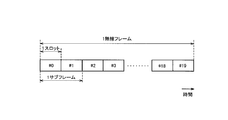
- FIG. 5 is a configuration diagram of a radio frame used in the LTE system.
- OFDMA Orthogonal Frequency Division Multiplexing Access
- SC-FDMA Single Carrier Frequency Multiple Access
- the radio frame is composed of 10 subframes arranged in the time direction, and each subframe is composed of two slots arranged in the time direction.
- the length of each subframe is 1 ms, and the length of each slot is 0.5 ms.
- Each subframe includes a plurality of resource blocks (RB) in the frequency direction and includes a plurality of symbols in the time direction.
- the resource block includes a plurality of subcarriers in the frequency direction.
- a frequency resource can be specified by a resource block
- a time resource can be specified by a subframe (or slot).
- the section of the first few symbols of each subframe is a control region used mainly as a physical downlink control channel (PDCCH) for transmitting a control signal.
- the remaining section of each subframe is an area that can be used as a physical downlink shared channel (PDSCH) mainly for transmitting user data.
- PDSCH physical downlink shared channel
- both ends in the frequency direction in each subframe are control regions mainly used as a physical uplink control channel (PUCCH) for transmitting a control signal.
- the central portion in the frequency direction in each subframe is an area that can be used as a physical uplink shared channel (PUSCH) mainly for transmitting user data.
- PUSCH physical uplink shared channel
- the LTE system supports D2D communication that is direct UE-to-UE communication.
- D2D communication will be described in comparison with normal communication (cellular communication) of the LTE system.
- the data path passes through the core network EPC 20.
- a data path is a communication path for user data (user plane).
- D2D communication a data path set between UEs does not pass through the EPC 20. Therefore, the traffic load of the EPC 20 can be reduced.
- the UE 100 discovers another UE 100 existing in the vicinity and starts D2D communication.
- the D2D communication includes a direct communication mode and a local relay mode (Locally Routed mode).
- FIG. 6 is a diagram for explaining a direct communication mode in D2D communication.
- the data path does not pass through the eNB 200.
- the UE 100-1D and the UE 100-2D that are close to each other directly perform radio communication with low transmission power in the cell of the eNB 200. Therefore, advantages such as a reduction in power consumption of the UE 100 and a reduction in interference with adjacent cells can be obtained.
- UE 100-1D and UE 100-2D are D2D UEs (D2D terminals) that perform D2D communication in the direct communication mode in the cell of eNB 200.
- the UE 100-1D and UE 100-2D in the connected state perform D2D communication using radio resources allocated from the eNB 200.
- UE 100-1D and UE 100-2D transmit / receive user data to / from each other, and transmit / receive control signals to / from eNB 200.
- control of D2D communication is performed by eNB200 initiative.
- Either one of the UE 100-1D and the UE 100-2D may be an anchor UE (anchor terminal) that can control the other UE in the D2D communication.
- the anchor UE may have a right to determine a radio resource used for D2D communication, and may be able to transmit a control signal to the other UE (communication partner UE).
- the other UE (communication partner UE) may transmit / receive the anchor signal to / from the anchor UE without transmitting / receiving the control signal to / from the eNB 200.
- UE 100-C is a cellular UE (cellular terminal) that performs cellular communication in a cell of eNB 200.
- the UE 100-C in the connected state performs cellular communication using radio resources allocated from the eNB 200.
- the UE 100-C transmits and receives user data and control signals to and from the eNB 200.
- the data path between the UEs passes through the eNB 200, but the data path does not pass through the EPC 20. That is, in the local relay mode, the UE 100-1D and the UE 100-2D perform wireless communication via the eNB 200 without passing through the EPC 20.
- the local relay mode can reduce the traffic load of the EPC 20, but has less merit than the direct communication mode. Therefore, in the first embodiment, the direct communication mode is mainly assumed.
- D2D communication is performed within a frequency band (so-called license band) assigned to the LTE system.
- a frequency band so-called license band assigned to the LTE system.
- D2D communication As a case where D2D communication is started, (a) a case where D2D communication is started after discovering a nearby terminal by performing an operation for discovering a nearby terminal, and (b) a nearby terminal is discovered. There is a case where D2D communication is started without performing the operation for.
- D2D communication is started when one of the UEs 100-1 and 100-2 discovers the other UE 100 in the vicinity.
- the UE 100 discovers other UEs 100 existing in the vicinity of the UE 100 in order to discover neighboring terminals (Discover) and / or the UE 100 is discovered from the other UEs 100 (Discoverable). It has a function.
- the UE 100-1 transmits a discovery signal (Discovery signal / Discoverable signal) used to discover a nearby terminal or to be discovered by a nearby terminal.
- the UE 100-2 that has received the discovery signal discovers the UE 100-1.
- the UE 100-2 transmits a response to the discovery signal, the UE 100-1 that has transmitted the discovery signal discovers the UE 100-2 that is a neighboring terminal.
- the UE 100 does not necessarily perform the D2D communication even if the UE 100 discovers a nearby terminal.
- the UE 100-1 and the UE 100-2 may negotiate and then perform the D2D communication after discovering each other. It may be determined.
- Each of the UE 100-1 and the UE 100-2 starts D2D communication when agreeing to perform D2D communication.
- the UE 100-1 may report the discovery of the nearby UE 100 (that is, the UE 100-2) to an upper layer (for example, an application).
- the application can execute processing based on the report (for example, processing for plotting the location of the UE 100-2 on map information).
- the UE 100 can report to the eNB 200 that a nearby terminal has been found, and can receive an instruction from the eNB 200 to perform communication with the nearby terminal through cellular communication or D2D communication.
- the UE 100-1 starts transmission of a signal for D2D communication (such as broadcast notification) without specifying a D2D communication partner.
- UE100 can start D2D communication irrespective of the presence or absence of the discovery of a nearby terminal.
- the UE 100-2 performing the signal standby operation for D2D communication performs synchronization or / and demodulation based on the signal from the UE 100-1.
- FIG. 7 is a diagram for explaining the operating environment according to the first embodiment.
- the MeNB (macro base station) 200-1 manages the cell 1 (macro cell).
- cell 1 is the serving cell of each of UEs 100-1 and 100-2.
- each of the UEs 100-1 and 100-2 is in a connected state in the cell 1.
- the PeNB (pico base station) 200-2 manages the cell 2 (pico cell) in the cell 1.
- PeNB 200-2 corresponds to an adjacent eNB of MeNB 200-1.
- Cell 2 is a cell having a smaller coverage than cell 1.
- the first embodiment assumes an operating environment in which the cell 2 (pico cell) is provided in the cell 1 (macro cell).
- the UEs 100-1 and 100-2 are connected to the cell 1 but are located in the vicinity of the cell 2. Therefore, assuming that the UEs 100-1 and 100-2 perform D2D communication, the transmission signal from the UEs 100-1 and / or 100-2 affects the cell 2 and the communication quality deteriorates in the cell 2. May occur.
- the UE 100-1 transmits a discovery signal related to discovery of a nearby terminal that can be a communication partner of D2D communication.
- the UE 100-1 that transmits the discovery signal may not perform D2D communication and may perform D2D communication.
- the discovery signal is a signal (Discovery signal) for discovering a nearby terminal.
- the discovery signal may be a signal (Discoverable signal) for discovery from a nearby terminal.
- the Discovery signal may be transmitted with a transmission power equivalent to a data signal (D2D communication signal) transmitted during D2D communication.
- FIG. 8 is an operation sequence diagram according to the first embodiment.
- the PeNB 200-2 shares information on radio resources (time / frequency resources) used by the UE 100-1 for transmitting the Discovery signal with the MeNB 200-1.
- information on radio resources used for transmitting the Discovery signal is notified from the MeNB 200-1 to the PeNB 200-2.
- the MeNB 200-1 may notify the PeNB 200-2 of the transmission timing of the Discovery signal before the transmission timing, and corresponds to the cycle or the cycle when the transmission timing of the Discovery signal is periodic.
- the timing (subframe or the like) may be notified to the PeNB 200-2.
- the MeNB 200-1 and / or PeNB 200-2 may perform control so as to stop the cellular communication and / or stop the D2D communication at the transmission timing of the Discovery signal.
- the UE 100-1 transmits a Discovery signal.
- the Discovery signal includes a UE identifier for identifying the UE 100-1.
- the Discovery signal may further include a cell identifier for identifying the cell of MeNB 200-1.
- PeNB 200-2 receives the Discovery signal from UE 100-1. Here, PeNB 200-2 detects reception of the Discovery signal based on information shared with MeNB 200-1.
- the PeNB 200-2 notifies the MeNB 200-1 of Discovery interference information (Indication) related to the received Discovery signal in response to the reception of the Discovery signal.
- the PeNB 200-2 determines to notify the Discovery interference information to the MeNB 200-1 when the received power of the Discovery signal exceeds the threshold (S103; Yes).
- the PeNB 200-2 generates Discovery interference information to be notified to the MeNB 200-1.
- the Discovery interference information includes the following information.
- the transmission power control information is, for example, information indicating a power reduction request (information indicating how much the transmission power should be reduced), an upper limit of transmission power (maximum transmission power), or a transmission power designation value.
- the Discovery interference information includes information on radio resources (resource blocks, subframes, frequency bands) that have received the Discovery signal, information on path loss (propagation loss) estimated from the reception power of the Discovery signal, and cells (cells) that have received the Discovery signal.
- the cell identifier of 2) may be included.
- a format example of Discovery interference information is shown in Table 1.
- the PeNB 200-2 notifies the Discovery interference information to the MeNB 200-1.
- the PeNB 200-2 may notify the Discovery interference information directly to the MeNB 200-1 on the X2 interface, or may indirectly notify the MeNB 200-1 on the S1 interface.
- PeNB 200-2 notifies Discovery interference information to all neighboring eNBs including MeNB 200-1.
- the PeNB 200-2 may notify the Discovery interference information only to the cell (cell 1) indicated by the cell identifier.
- the MeNB 200-1 may return a response to the PeNB 200-2 when it is confirmed that the UE corresponding to the UE identifier included in the Discovery interference information from the PeNB 200-2 exists in its own cell. On the other hand, when the UE corresponding to the UE identifier does not exist in the own cell, the MeNB 200-1 may notify the PeNB 200-2 to that effect.
- the UE 100-2 receives the Discovery signal from the UE 100-1.
- the UE 100-2 transmits Discovery power information regarding the received power of the Discovery signal in the UE 100-2 to the serving cell (cell 1).
- the UE 100-2 determines to transmit the Discovery power information to the MeNB 200-1 when the reception power of the Discovery signal exceeds the threshold (S106; Yes).
- the UE 100-2 generates Discovery power information to be transmitted to the MeNB 200-1.
- the Discovery power information includes the following information.
- the reception power of the Discovery signal in the UE 100-2 or the ratio of the reception power of the Discovery signal and / or the D2D communication signal to the required reception power (information indicating how much the transmission power of the UE 100-1 can be reduced).
- the required reception power is reception power required to establish or maintain D2D communication.
- the UE 100-2 may transmit Discovery power information in response to a request or setting from MeNB 200-2.
- the UE 100-2 may transmit the D2D request for requesting the start of the D2D communication by including the Discovery power information.
- step S108 the UE 100-2 transmits (reports) the Discovery power information to the MeNB 200-1.
- the MeNB 200-1 transmits power control information for reducing the transmission power of the Discovery signal and / or the D2D communication signal in response to receiving the Discovery interference information from the PeNB 200-2. Send to.
- the MeNB 200-1 determines whether to reduce the transmission power of the UE 100-1 based on the Discovery interference information from the PeNB 200-2 and the Discovery power information from the UE 100-2. Determine whether. For example, the MeNB 200-1 specifies “transmission power that can be reduced” from the Discovery power information, and specifies “transmission power that should be reduced” from the Discovery interference information. Then, the MeNB 200-1 determines to decrease the transmission power of the UE 100-1 when the transmission power to be decreased is equal to or lower than the transmission power that can be decreased.
- the MeNB 200-1 may negotiate with the PeNB 200-2 regarding the amount of reduction in the transmission power of the UE 100-1. For example, the MeNB 200-1 notifies the PeNB 200-2 of the transmission power that can be reduced (or the transmission power after the reduction) (S110). The PeNB 200-2 determines whether or not to accept the transmission power that can be decreased (or transmission power after the decrease) (S111), and notifies the determination result to the MeNB 200-1 (S112).
- the MeNB 200-1 controls not to start the D2D communication when the UE 100-1 and 100-2 are not performing the D2D communication when the transmission power to be reduced exceeds the transmission power that can be reduced. May be.
- the MeNB 200-1 determines the reduced transmission power (the transmission power of the Discovery signal and / or the D2D communication signal) for the UE 100-1.
- MeNB200-1 notifies the determined transmission power (P Disvovery set) to UE 100-1 (set).
- the UE 100-1 transmits the Discovery signal and / or the D2D communication signal with the transmission power notified from the MeNB 200-1 (S114).
- the UE 100-1 may notify the UE 100-2 of the notified transmission power.
- the MeNB 200-1 in response to the PeNB 200-2 receiving the Discovery signal, notifies the MeNB 200-1 of the Discovery interference information (Indication) regarding the received Discovery signal.
- the Discovery interference information Indication
- transmission power control for suppressing interference can be performed.
- the MeNB 200-1 transmits instruction information for instructing transmission of a Discovery signal to the UE 100-1 performing D2D communication.
- the UE 100-1 performing D2D communication transmits a Discovery signal in response to reception of the instruction information.
- the MeNB 200-1 may transmit the instruction information to the UE 100-1 when determining that the geographical position of the UE 100-1 performing D2D communication is close to the geographical position of the PeNB 200-2. Since the technique for obtaining the UE location information is well known, description thereof is omitted here.
- the MeNB 200-1 may periodically transmit the instruction information to the UE 100-1, or may transmit instruction information for instructing transmission of a periodic Discovery signal to the UE 100-1.
- the MeNB 200-1 may transmit the instruction information to the UE 100-1 when receiving the Discovery interference information from the PeNB 200-2.
- the MeNB 200-1 may transmit the instruction information to the UE 100-1 in response to a request or setting from the EPC 20.
- PeNB 200-2 receives the Discovery signal and transmits Discovery interference information to MeNB 200-1, as in the first embodiment described above.
- the MeNB 200-1 performs any of the following interference avoidance controls when the UE 100-1 is identified as an interfering UE based on the Discovery interference information from the PeNB 200-2.
- the radio resource of the change destination is a resource for D2D that is notified in advance from the PeNB 200-2 to the MeNB 200-1, a blank subframe in which the PeNB 200-2 does not perform uplink allocation, or another band that does not operate the PeNB It is.
- ⁇ Instructs UE 100-1 to switch from D2D communication to cellular communication.
- the MeNB 200-1 stops the transmission of the Discovery signal when the UE 100-1 periodically transmits the Discovery signal and the MeNB 200-1 identifies the UE 100-1 as an interfering UE based on the Discovery interference information. May be transmitted to the UE 100-1.
- the MeNB 200-1 transmits the instruction information instructing the UE 100-1 performing D2D communication to transmit the Discovery signal, so that the UE 100-1 interferes with the adjacent eNB. Can be confirmed (whether or not it is an interfering UE).
- the cluster head which is UE which controls D2D communication in D2D UE group (cluster) which consists of several UE100 which adjoins mutually performs operation
- the CHUE can perform the same operation as the PeNB 200-2 in S101 to S105 and S110 to S112 described above.
- CHUE is a reference for synchronization in a cluster and is a UE that controls D2D communication in the cluster. That is, CHUE may be the anchor UE described above.
- the CHUE may belong to a cluster to which the UE 100-1 and the UE 100-2 belong, or may belong to different clusters.
- CHUE and PeNB 200-2 are common in that radio resource scheduling is possible.
- the UE 100-1 transmits the Discovery signal and / or the D2D communication signal with the transmission power notified from the MeNB 200-1 (see S114), but is not limited thereto.
- the UE 100-1 may determine the transmission power of the Discovery signal and / or the D2D communication signal based on the transmission power notified from the MeNB 200-1. Specifically, the UE 100-1 determines the transmission power equal to or lower than the notified transmission power as the transmission power of the Discovery signal and / or the D2D communication signal.
- the UE 100-1 may notify the UE 100-1 of the determined transmission power. Note that the UE 100-1 may determine the transmission power of the Discovery signal and / or the D2D communication signal when scheduling radio resources to be used for D2D communication.
- the UE 100-2 transmits (reports) the Discovery power information to the MeNB 200-1 (see S108), but is not limited thereto.
- the UE 100-2 sends the Discovery power information to the MeNB 200-1 via the UE 100-1 located in the cell coverage managed by the MeNB 200-1. It may be transmitted (reported).
- the UE 100-1 receives the Discovery power information from the UE 100-2 located outside the cell coverage of the MeNB 200-1, instead of transmitting the Discovery power information to the MeNB 200-1, the UE 100-1 has reduced transmission power ( The transmission power of the Discovery signal and / or the D2D communication signal) may be determined.
- MeNB200-1 uses the PDCCH (Physical Downlink Control Channerl), determined transmission power (P Disvovery setting) may notify the UE 100-1.
- PDCCH Physical Downlink Control Channerl
- determined transmission power P Disvovery setting
- the direct communication mode in D2D communication is mainly assumed, but the local relay mode may be applied instead of the direct communication mode.
- the present invention is not limited to the LTE system, and the present invention may be applied to a system other than the LTE system.
- the communication control method, the base station, and the user terminal according to the present invention can suppress interference between cellular communication and D2D communication, they are useful in the mobile communication field.
Landscapes
- Engineering & Computer Science (AREA)
- Computer Networks & Wireless Communication (AREA)
- Signal Processing (AREA)
- Databases & Information Systems (AREA)
- Quality & Reliability (AREA)
- Mobile Radio Communication Systems (AREA)
Abstract
Description
第1実施形態及び第2実施形態に係る通信制御方法は、データパスがコアネットワークを経由するセルラ通信と、データパスが前記コアネットワークを経由しない直接的な端末間通信であるD2D通信と、をサポートする移動通信システムにおいて用いられる。前記通信制御方法は、第1の基地局のセルに在圏する第1のユーザ端末が、前記D2D通信の通信相手になり得る近傍端末の発見に関する発見用信号を送信する送信ステップと、前記発見用信号を第2の基地局が受信したことに応じて、受信した発見用信号に関する干渉情報を、前記通信装置から前記第1の基地局に通知する通知ステップと、を有する。
以下、図面を参照して、3GPP規格に準拠して構成される移動通信システム(LTEシステム)にD2D通信を導入する場合の実施形態を説明する。
図1は、第1実施形態に係るLTEシステムの構成図である。図1に示すように、LTEシステムは、複数のUE(User Equipment)100と、E-UTRAN(Evolved Universal Terrestrial Radio Access Network)10と、EPC(Evolved Packet Core)20と、を含む。E-UTRAN10は無線アクセスネットワークに相当し、EPC20はコアネットワークに相当する。E-UTRAN10及びEPC20は、LTEシステムのネットワークを構成する。
第1実施形態に係るLTEシステムは、直接的なUE間通信であるD2D通信をサポートする。ここでは、D2D通信を、LTEシステムの通常の通信(セルラ通信)と比較して説明する。
次に、第1実施形態に係る動作について説明する。図7は、第1実施形態に係る動作環境を説明するための図である。図7に示すように、MeNB(マクロ基地局)200-1は、セル1(マクロセル)を管理する。セル1には、UE100-1及び100-2が在圏する。すなわち、セル1は、UE100-1及び100-2のそれぞれのサービングセルである。第1実施形態では、UE100-1及び100-2のそれぞれは、セル1において接続状態にある。

第2実施形態について、第1実施形態との相違点を説明する。第2実施形態に係る動作環境は第1実施形態と同様である。以下において、第2実施形態に係る動作を説明する。
上述した各実施形態では、MeNB200-1(マクロセル)及びPeNB200-2(ピコセル)が設置された動作環境を例に説明したが、同種のeNB(同種のセル)が設置された動作環境に本発明を適用してもよい。
Claims (20)
- データパスがコアネットワークを経由するセルラ通信と、データパスが前記コアネットワークを経由しない直接的な端末間通信であるD2D通信と、をサポートする移動通信システムにおいて用いられる通信制御方法であって、
第1の基地局のセルに在圏する第1のユーザ端末が、前記D2D通信の通信相手になり得る近傍端末の発見に関する発見用信号を送信する送信ステップと、
前記発見用信号を通信装置が受信したことに応じて、受信した発見用信号に関する干渉情報を、前記通信装置から前記第1の基地局に通知する通知ステップと、
を有することを特徴とする通信制御方法。 - 前記通信装置は、前記第1の基地局の隣接基地局であることを特徴とする請求項1に記載の通信制御方法。
- 前記通知ステップにおいて、前記通信装置は、前記発見用信号の受信電力が閾値を超える場合に、前記干渉情報を前記第1の基地局に通知することを特徴とする請求項1に記載の通信制御方法。
- 前記発見用信号は、前記第1のユーザ端末を識別するための端末識別子を含み、
前記通知ステップにおいて、前記通信装置は、前記端末識別子を前記干渉情報に含めることを特徴とする請求項1に記載の通信制御方法。 - 前記通知ステップにおいて、前記通信装置は、前記通信装置における前記発見用信号の受信電力、又は、前記発見用信号及び/又はD2D通信信号の送信電力制御情報を、前記干渉情報に含めることを特徴とする請求項1に記載の通信制御方法。
- 前記通知ステップにおいて、前記通信装置は、前記第1の基地局を含む全ての隣接基地局に対して前記干渉情報を通知することを特徴とする請求項2に記載の通信制御方法。
- 前記発見用信号は、前記第1の基地局のセルを識別するためのセル識別子を含み、
前記通知ステップにおいて、前記通信装置は、前記発見用信号に含まれる前記セル識別子に基づいて、前記第1の基地局に対して前記干渉情報を通知することを特徴とする請求項1に記載の通信制御方法。 - 前記通信装置が、前記第1のユーザ端末が前記発見用信号の送信に使用する無線リソースの情報を前記第1の基地局と共有するステップと、
前記通信装置が、前記共有した情報に基づいて、前記発見用信号の受信を検知するステップと、
をさらに有することを特徴とする請求項1に記載の通信制御方法。 - 前記発見用信号を第2のユーザ端末が受信したことに応じて、前記第2のユーザ端末における前記発見用信号の受信電力に関する電力情報を、前記第2のユーザ端末から、前記第2のユーザ端末のサービングセルに送信するステップをさらに有することを特徴とする請求項1に記載の通信制御方法。
- 前記第1の基地局が前記干渉情報を受信したことに応じて、前記発見用信号及び/又はD2D通信信号の送信電力を低下させるための電力制御情報を、前記第1の基地局から前記第1のユーザ端末に送信するステップをさらに有することを特徴とする請求項1に記載の通信制御方法。
- 前記第1の基地局が、前記D2D通信を行っている前記第1のユーザ端末に対して、前記発見用信号の送信を指示する指示情報を送信する指示ステップをさらに有し、
前記送信ステップにおいて、前記D2D通信を行っている前記第1のユーザ端末は、前記指示情報の受信に応じて、前記発見用信号を送信することを特徴とする請求項1に記載の通信制御方法。 - 前記指示ステップにおいて、前記第1の基地局は、前記干渉情報の受信に応じて、前記D2D通信を行っている前記第1のユーザ端末に対して前記指示情報を送信することを特徴とする請求項11に記載の通信制御方法。
- 前記送信ステップにおいて、前記D2D通信を行っている前記第1のユーザ端末は、前記発見用信号を周期的に送信し、
前記通信制御方法は、前記第1の基地局が前記干渉情報に基づいて前記第1のユーザ端末を与干渉端末として特定した場合に、前記発見用信号の送信停止を指示する指示情報を前記第1の基地局から前記第1のユーザ端末に送信するステップをさらに有することを特徴とする請求項12に記載の通信制御方法。 - 前記指示ステップにおいて、前記第1の基地局は、前記D2D通信を行っている前記第1のユーザ端末の地理的位置が前記第2の基地局の地理的位置と近接すると判断した場合に、前記D2D通信を行っている前記第1のユーザ端末に対して前記指示情報を送信することを特徴とする請求項11に記載の通信制御方法。
- 前記通信制御方法は、前記D2D通信を行っている前記第1のユーザ端末を前記第1の基地局が前記干渉情報に基づいて与干渉端末として特定した場合に、干渉回避制御として、前記D2D通信の送信電力を低下させるための電力制御情報、又は前記D2D通信の無線リソースを変更するためのリソース情報を当該第1のユーザ端末に送信するステップをさらに有することを特徴とする請求項12に記載の通信制御方法。
- 前記通信制御方法は、前記干渉回避制御の実行可否を示す情報を前記第1の基地局から前記通信装置に通知するステップをさらに有することを特徴とする請求項15に記載の通信制御方法。
- 前記通信装置は、相互に近接する複数のユーザ端末からなるクラスタにおいて、前記D2D通信を制御するユーザ端末であることを特徴とする請求項1に記載の通信制御方法。
- データパスがコアネットワークを経由するセルラ通信と、データパスが前記コアネットワークを経由しない直接的な端末間通信であるD2D通信と、をサポートする移動通信システムにおいて用いられる基地局であって、
他の基地局のセルに在圏するユーザ端末から送信される信号であって、かつ前記D2D通信の通信相手になり得る近傍端末の発見に関する発見用信号を前記基地局が受信したことに応じて、受信した発見用信号に関する干渉情報を前記他の基地局に通知する制御部を有することを特徴とする基地局。 - データパスがコアネットワークを経由するセルラ通信と、データパスが前記コアネットワークを経由しない直接的な端末間通信であるD2D通信と、をサポートする移動通信システムにおいて用いられる基地局であって、
前記基地局のセルに在圏しており、かつ前記D2D通信を行っているユーザ端末に対して、前記D2D通信の通信相手になり得る近傍端末の発見に関する発見用信号の送信を指示する指示情報を送信する制御部を有することを特徴とする基地局。 - データパスがコアネットワークを経由するセルラ通信と、データパスが前記コアネットワークを経由しない直接的な端末間通信であるD2D通信と、をサポートする移動通信システムにおいて、基地局のセルに在圏しているユーザ端末であって、
前記ユーザ端末が前記D2D通信を行っている場合において、前記D2D通信の通信相手になり得る近傍端末の発見に関する発見用信号の送信を指示する指示情報を前記基地局から受信した場合に、前記発見用信号を送信する制御部を有することを特徴とするユーザ端末。
Priority Applications (4)
| Application Number | Priority Date | Filing Date | Title |
|---|---|---|---|
| US14/768,104 US9712989B2 (en) | 2013-02-19 | 2014-02-18 | Communication control method, base station, and user terminal |
| EP14754792.1A EP2961241A4 (en) | 2013-02-19 | 2014-02-18 | COMMUNICATION CONTROL METHOD, BASE STATION AND USER TERMINAL |
| JP2015501457A JP6166343B2 (ja) | 2013-02-19 | 2014-02-18 | 通信制御方法、基地局及びユーザ端末 |
| US15/642,125 US10200848B2 (en) | 2013-02-19 | 2017-07-05 | Communication control method, base station, and user terminal |
Applications Claiming Priority (2)
| Application Number | Priority Date | Filing Date | Title |
|---|---|---|---|
| US201361766468P | 2013-02-19 | 2013-02-19 | |
| US61/766,468 | 2013-02-19 |
Related Child Applications (2)
| Application Number | Title | Priority Date | Filing Date |
|---|---|---|---|
| US14/768,104 A-371-Of-International US9712989B2 (en) | 2013-02-19 | 2014-02-18 | Communication control method, base station, and user terminal |
| US15/642,125 Continuation US10200848B2 (en) | 2013-02-19 | 2017-07-05 | Communication control method, base station, and user terminal |
Publications (1)
| Publication Number | Publication Date |
|---|---|
| WO2014129456A1 true WO2014129456A1 (ja) | 2014-08-28 |
Family
ID=51391246
Family Applications (1)
| Application Number | Title | Priority Date | Filing Date |
|---|---|---|---|
| PCT/JP2014/053750 WO2014129456A1 (ja) | 2013-02-19 | 2014-02-18 | 通信制御方法、基地局及びユーザ端末 |
Country Status (4)
| Country | Link |
|---|---|
| US (2) | US9712989B2 (ja) |
| EP (1) | EP2961241A4 (ja) |
| JP (3) | JP6166343B2 (ja) |
| WO (1) | WO2014129456A1 (ja) |
Families Citing this family (2)
| Publication number | Priority date | Publication date | Assignee | Title |
|---|---|---|---|---|
| US9918266B2 (en) * | 2014-10-06 | 2018-03-13 | Telefonaktiebolaget Lm Ericsson (Publ) | Activation and deactivation of a secondary cell for device-to-device user equipment |
| CN107340504B (zh) * | 2017-07-03 | 2020-04-07 | 中国人民解放军海军航空大学 | 基于frft域峰值特性的压制干扰存在性检测方法 |
Citations (5)
| Publication number | Priority date | Publication date | Assignee | Title |
|---|---|---|---|---|
| WO2011116017A1 (en) * | 2010-03-17 | 2011-09-22 | Qualcomm Incorporated | Method and apparatus for establishing and maintaining peer-to-peer (p2p) communication on unlicensed spectrum |
| WO2011123516A2 (en) * | 2010-03-31 | 2011-10-06 | Qualcomm Incorporated | Methods and apparatus for determining a communications mode and/or using a determined communications mode |
| WO2011130623A2 (en) * | 2010-04-15 | 2011-10-20 | Qualcomm Incorporated | Network-assisted peer discovery |
| WO2011143496A1 (en) * | 2010-05-12 | 2011-11-17 | Qualcomm Incorporated | Resource coordination for peer-to-peer groups through distributed negotiation |
| WO2012144941A1 (en) * | 2011-04-19 | 2012-10-26 | Telefonaktiebolaget L M Ericsson (Publ) | Radio base stations and methods therein for handling interference and scheduling radio resources accordingly |
Family Cites Families (16)
| Publication number | Priority date | Publication date | Assignee | Title |
|---|---|---|---|---|
| JPH08205253A (ja) * | 1995-01-27 | 1996-08-09 | Fuji Electric Co Ltd | 小電力無線式情報収集システム |
| CA2625623A1 (en) * | 2005-11-11 | 2007-05-18 | Telefonaktiebolaget L M Ericsson (Publ) | Method and apparatus for limiting peer-to-peer communication interference |
| US20120124231A9 (en) * | 2007-07-10 | 2012-05-17 | Qualcomm Incorporated | Methods and apparatus for controlling switching between resources and/or communicating resource change information in a wireless communications system |
| US8825046B2 (en) * | 2008-02-01 | 2014-09-02 | Qualcomm Incorporated | Short-term interference mitigation in a wireless communication system |
| JP5063517B2 (ja) * | 2008-07-31 | 2012-10-31 | 株式会社日立製作所 | 無線ネットワークシステム及び無線ネットワークシステムの周波数選択方法 |
| US8331965B2 (en) * | 2009-06-12 | 2012-12-11 | Qualcomm Incorporated | Methods and apparatus for controlling resource use in a wireless communications system |
| KR101712669B1 (ko) * | 2010-07-13 | 2017-03-06 | 삼성전자주식회사 | 무선 통신 시스템에서 피투피 통신의 자원 관리 방법 및 장치 |
| US10517098B2 (en) * | 2010-07-30 | 2019-12-24 | Qualcomm Incorporated | Interference coordination for peer-to-peer (P2P) communication and wide area network (WAN) communication |
| US8812008B2 (en) * | 2011-03-28 | 2014-08-19 | Qualcomm Incorporated | Methods and apparatus for assigning resources to schedule peer-to-peer communications in WWAN |
| US9288773B2 (en) | 2011-04-22 | 2016-03-15 | Qualcomm Incorporated | Methods and apparatus for controlling interference from peer discovery in WWAN |
| US9125096B2 (en) * | 2012-05-04 | 2015-09-01 | Qualcomm Incorporated | Method and apparatus for reducing interference in a wireless system |
| JP5893141B2 (ja) | 2012-07-27 | 2016-03-23 | 京セラ株式会社 | 移動通信システム、ユーザ端末、プロセッサ及び基地局 |
| US9918318B2 (en) * | 2012-07-27 | 2018-03-13 | Kyocera Corporation | Mobile communication system and mobile communication method |
| US11496948B2 (en) * | 2012-10-19 | 2022-11-08 | Samsung Electronics Co., Ltd. | System and method for ad-hoc/network assisted device discovery protocol for device to device communications |
| KR20150007753A (ko) | 2013-07-12 | 2015-01-21 | 삼성전자주식회사 | 무선 셀룰라 통신 시스템에서 기지국 간 단말의 단말 대 단말 발견 신호 전송 방법 및 장치 |
| JP2016031857A (ja) * | 2014-07-29 | 2016-03-07 | アイリスオーヤマ株式会社 | 照明器具 |
-
2014
- 2014-02-18 EP EP14754792.1A patent/EP2961241A4/en not_active Withdrawn
- 2014-02-18 JP JP2015501457A patent/JP6166343B2/ja active Active
- 2014-02-18 WO PCT/JP2014/053750 patent/WO2014129456A1/ja active Application Filing
- 2014-02-18 US US14/768,104 patent/US9712989B2/en active Active
-
2017
- 2017-06-22 JP JP2017122361A patent/JP6268320B2/ja active Active
- 2017-07-05 US US15/642,125 patent/US10200848B2/en active Active
- 2017-12-25 JP JP2017247988A patent/JP6302129B1/ja active Active
Patent Citations (5)
| Publication number | Priority date | Publication date | Assignee | Title |
|---|---|---|---|---|
| WO2011116017A1 (en) * | 2010-03-17 | 2011-09-22 | Qualcomm Incorporated | Method and apparatus for establishing and maintaining peer-to-peer (p2p) communication on unlicensed spectrum |
| WO2011123516A2 (en) * | 2010-03-31 | 2011-10-06 | Qualcomm Incorporated | Methods and apparatus for determining a communications mode and/or using a determined communications mode |
| WO2011130623A2 (en) * | 2010-04-15 | 2011-10-20 | Qualcomm Incorporated | Network-assisted peer discovery |
| WO2011143496A1 (en) * | 2010-05-12 | 2011-11-17 | Qualcomm Incorporated | Resource coordination for peer-to-peer groups through distributed negotiation |
| WO2012144941A1 (en) * | 2011-04-19 | 2012-10-26 | Telefonaktiebolaget L M Ericsson (Publ) | Radio base stations and methods therein for handling interference and scheduling radio resources accordingly |
Non-Patent Citations (2)
| Title |
|---|
| "TR 22.803 V12.0.0", 3GPP TECHNICAL REPORT, December 2012 (2012-12-01) |
| See also references of EP2961241A4 |
Also Published As
| Publication number | Publication date |
|---|---|
| US20170311145A1 (en) | 2017-10-26 |
| EP2961241A4 (en) | 2016-12-21 |
| JP6302129B1 (ja) | 2018-03-28 |
| US9712989B2 (en) | 2017-07-18 |
| US10200848B2 (en) | 2019-02-05 |
| EP2961241A1 (en) | 2015-12-30 |
| US20160007183A1 (en) | 2016-01-07 |
| JPWO2014129456A1 (ja) | 2017-02-02 |
| JP6166343B2 (ja) | 2017-07-19 |
| JP2018074608A (ja) | 2018-05-10 |
| JP6268320B2 (ja) | 2018-01-24 |
| JP2017195626A (ja) | 2017-10-26 |
Similar Documents
| Publication | Publication Date | Title |
|---|---|---|
| JP6253833B2 (ja) | ユーザ端末、プロセッサ、及び方法 | |
| JP6328132B2 (ja) | 移動通信システム及びユーザ端末 | |
| JP6224861B2 (ja) | ユーザ端末、プロセッサ、及び方法 | |
| WO2014034286A1 (ja) | 移動通信システム、基地局、ユーザ端末、及びプロセッサ | |
| WO2014129465A1 (ja) | 通信制御方法、ユーザ端末及び基地局 | |
| WO2014157398A1 (ja) | 通信制御方法及びプロセッサ | |
| JP5852261B2 (ja) | 移動通信システム、ユーザ端末、基地局、プロセッサ及び通信制御方法 | |
| WO2014069221A1 (ja) | 移動通信システム、ユーザ端末、基地局、プロセッサ及び通信制御方法 | |
| WO2014069222A1 (ja) | 移動通信システム、ユーザ端末、基地局、プロセッサ及び通信制御方法 | |
| JP6140292B2 (ja) | ネットワーク装置及びユーザ端末 | |
| JP6302129B1 (ja) | 基地局及びプロセッサ | |
| JP6200078B2 (ja) | ユーザ端末、プロセッサ及び方法 | |
| JP6140270B2 (ja) | 移動通信システム、基地局、及びユーザ端末 | |
| JP6140014B2 (ja) | ユーザ端末、基地局、及びプロセッサ | |
| JP6398032B2 (ja) | 移動通信システム、ユーザ端末、基地局、及びプロセッサ |
Legal Events
| Date | Code | Title | Description |
|---|---|---|---|
| 121 | Ep: the epo has been informed by wipo that ep was designated in this application |
Ref document number: 14754792 Country of ref document: EP Kind code of ref document: A1 |
|
| ENP | Entry into the national phase |
Ref document number: 2015501457 Country of ref document: JP Kind code of ref document: A |
|
| WWE | Wipo information: entry into national phase |
Ref document number: 14768104 Country of ref document: US |
|
| NENP | Non-entry into the national phase |
Ref country code: DE |
|
| WWE | Wipo information: entry into national phase |
Ref document number: 2014754792 Country of ref document: EP |