WO2015005097A1 - Moteur à six temps et procédé pour faire fonctionner un moteur à six temps - Google Patents
Moteur à six temps et procédé pour faire fonctionner un moteur à six temps Download PDFInfo
- Publication number
- WO2015005097A1 WO2015005097A1 PCT/JP2014/066394 JP2014066394W WO2015005097A1 WO 2015005097 A1 WO2015005097 A1 WO 2015005097A1 JP 2014066394 W JP2014066394 W JP 2014066394W WO 2015005097 A1 WO2015005097 A1 WO 2015005097A1
- Authority
- WO
- WIPO (PCT)
- Prior art keywords
- stroke
- intake
- valve
- exhaust
- dead center
- Prior art date
Links
Images


Classifications
-
- F—MECHANICAL ENGINEERING; LIGHTING; HEATING; WEAPONS; BLASTING
- F02—COMBUSTION ENGINES; HOT-GAS OR COMBUSTION-PRODUCT ENGINE PLANTS
- F02D—CONTROLLING COMBUSTION ENGINES
- F02D13/00—Controlling the engine output power by varying inlet or exhaust valve operating characteristics, e.g. timing
- F02D13/02—Controlling the engine output power by varying inlet or exhaust valve operating characteristics, e.g. timing during engine operation
- F02D13/0261—Controlling the valve overlap
-
- F—MECHANICAL ENGINEERING; LIGHTING; HEATING; WEAPONS; BLASTING
- F01—MACHINES OR ENGINES IN GENERAL; ENGINE PLANTS IN GENERAL; STEAM ENGINES
- F01L—CYCLICALLY OPERATING VALVES FOR MACHINES OR ENGINES
- F01L1/00—Valve-gear or valve arrangements, e.g. lift-valve gear
- F01L1/02—Valve drive
- F01L1/04—Valve drive by means of cams, camshafts, cam discs, eccentrics or the like
- F01L1/047—Camshafts
-
- F—MECHANICAL ENGINEERING; LIGHTING; HEATING; WEAPONS; BLASTING
- F01—MACHINES OR ENGINES IN GENERAL; ENGINE PLANTS IN GENERAL; STEAM ENGINES
- F01L—CYCLICALLY OPERATING VALVES FOR MACHINES OR ENGINES
- F01L1/00—Valve-gear or valve arrangements, e.g. lift-valve gear
- F01L1/02—Valve drive
- F01L1/04—Valve drive by means of cams, camshafts, cam discs, eccentrics or the like
- F01L1/08—Shape of cams
-
- F—MECHANICAL ENGINEERING; LIGHTING; HEATING; WEAPONS; BLASTING
- F01—MACHINES OR ENGINES IN GENERAL; ENGINE PLANTS IN GENERAL; STEAM ENGINES
- F01L—CYCLICALLY OPERATING VALVES FOR MACHINES OR ENGINES
- F01L1/00—Valve-gear or valve arrangements, e.g. lift-valve gear
- F01L1/36—Valve-gear or valve arrangements, e.g. lift-valve gear peculiar to machines or engines of specific type other than four-stroke cycle
- F01L1/38—Valve-gear or valve arrangements, e.g. lift-valve gear peculiar to machines or engines of specific type other than four-stroke cycle for engines with other than four-stroke cycle, e.g. with two-stroke cycle
-
- F—MECHANICAL ENGINEERING; LIGHTING; HEATING; WEAPONS; BLASTING
- F02—COMBUSTION ENGINES; HOT-GAS OR COMBUSTION-PRODUCT ENGINE PLANTS
- F02B—INTERNAL-COMBUSTION PISTON ENGINES; COMBUSTION ENGINES IN GENERAL
- F02B75/00—Other engines
- F02B75/02—Engines characterised by their cycles, e.g. six-stroke
- F02B75/021—Engines characterised by their cycles, e.g. six-stroke having six or more strokes per cycle
-
- F—MECHANICAL ENGINEERING; LIGHTING; HEATING; WEAPONS; BLASTING
- F02—COMBUSTION ENGINES; HOT-GAS OR COMBUSTION-PRODUCT ENGINE PLANTS
- F02D—CONTROLLING COMBUSTION ENGINES
- F02D13/00—Controlling the engine output power by varying inlet or exhaust valve operating characteristics, e.g. timing
- F02D13/02—Controlling the engine output power by varying inlet or exhaust valve operating characteristics, e.g. timing during engine operation
-
- F—MECHANICAL ENGINEERING; LIGHTING; HEATING; WEAPONS; BLASTING
- F02—COMBUSTION ENGINES; HOT-GAS OR COMBUSTION-PRODUCT ENGINE PLANTS
- F02B—INTERNAL-COMBUSTION PISTON ENGINES; COMBUSTION ENGINES IN GENERAL
- F02B1/00—Engines characterised by fuel-air mixture compression
-
- F—MECHANICAL ENGINEERING; LIGHTING; HEATING; WEAPONS; BLASTING
- F02—COMBUSTION ENGINES; HOT-GAS OR COMBUSTION-PRODUCT ENGINE PLANTS
- F02B—INTERNAL-COMBUSTION PISTON ENGINES; COMBUSTION ENGINES IN GENERAL
- F02B1/00—Engines characterised by fuel-air mixture compression
- F02B1/02—Engines characterised by fuel-air mixture compression with positive ignition
- F02B1/04—Engines characterised by fuel-air mixture compression with positive ignition with fuel-air mixture admission into cylinder
-
- F—MECHANICAL ENGINEERING; LIGHTING; HEATING; WEAPONS; BLASTING
- F02—COMBUSTION ENGINES; HOT-GAS OR COMBUSTION-PRODUCT ENGINE PLANTS
- F02B—INTERNAL-COMBUSTION PISTON ENGINES; COMBUSTION ENGINES IN GENERAL
- F02B3/00—Engines characterised by air compression and subsequent fuel addition
- F02B3/06—Engines characterised by air compression and subsequent fuel addition with compression ignition
-
- F—MECHANICAL ENGINEERING; LIGHTING; HEATING; WEAPONS; BLASTING
- F02—COMBUSTION ENGINES; HOT-GAS OR COMBUSTION-PRODUCT ENGINE PLANTS
- F02F—CYLINDERS, PISTONS OR CASINGS, FOR COMBUSTION ENGINES; ARRANGEMENTS OF SEALINGS IN COMBUSTION ENGINES
- F02F1/00—Cylinders; Cylinder heads
- F02F1/24—Cylinder heads
- F02F2001/244—Arrangement of valve stems in cylinder heads
- F02F2001/247—Arrangement of valve stems in cylinder heads the valve stems being orientated in parallel with the cylinder axis
Definitions
- the present invention relates to a 6-cycle engine in which an intake stroke is performed after a piston reciprocates once after an exhaust stroke is performed, and an operation method of the 6-cycle engine.
- the thermal efficiency of the engine can be improved by promoting cooling in the cylinder, advancing the ignition timing, and increasing the compression ratio.
- a conventional engine in which cooling in a cylinder is promoted there is a six-cycle engine in which an intake stroke is performed after a piston reciprocates once after an exhaust stroke.
- This 6-cycle engine has 6 strokes, in which a scavenging stroke consisting of a second intake stroke and a second compression stroke is further added to four strokes including an intake stroke, a compression stroke, an expansion stroke, and an exhaust stroke. It is implemented sequentially.
- This type of 6-cycle engine has two main problems as described later.
- the first problem is that pump loss occurs due to the intake of fresh air due to the opening of the intake valve in the second intake stroke.
- the second problem is that air in which oxygen is not consumed by combustion is discharged into the exhaust passage by opening the exhaust valve in the second exhaust stroke. That is, there is a problem that the oxygen amount of the air is detected by the O 2 sensor in the exhaust passage and the air-fuel ratio is calculated to an abnormal value.
- the amount of oxygen flowing into the catalyst in the exhaust passage becomes excessive, there arises a problem that exhaust gas cannot be sufficiently purified.
- Patent Document 1 also discloses an operation method in which water is injected into the cylinder during the cooling period between the exhaust stroke and the intake stroke to further cool the inside of the cylinder.
- the operation method of the 6-cycle engine disclosed in Patent Document 1 has the following three problems.
- the first problem is that the inside of the cylinder is not cooled as expected. This is because the difference between the temperature of the burned gas sucked into the cylinder during the cooling period and the temperature of the cylinder is small.
- the second problem is that a large amount of burned gas flows into the cylinder during the cooling period. That is, since the intake stroke is started with a large amount of burned gas remaining in the combustion chamber, the ratio of burned gas in the cylinder increases after the intake stroke ends in many operating regions. . In addition, there is a high possibility that the burned gas in the combustion chamber will flow back into the intake passage due to a pressure difference during valve overlap when the intake stroke starts. Thus, if the gas exchange in the combustion chamber is not performed correctly, the combustion deteriorates and the thermal efficiency of the engine is significantly reduced.
- the third problem occurs when an operation method in which water is injected into the cylinder in order to increase the cooling effect.
- the engine must be equipped with auxiliary equipment such as an injector for water injection and a water storage tank, and the engine becomes large.
- the present invention has been made to solve such a problem.
- a 6-cycle engine in which gas exchange in a cylinder is correctly performed to increase thermal efficiency and a high cooling effect can be obtained using only engine components. And it aims at providing the operating method of a 6 cycle engine.
- a six-cycle engine includes a cylinder, a piston inserted into the cylinder and reciprocating between a bottom dead center and a top dead center, and a cylinder attached to the cylinder.
- a fuel injection injector for injecting fuel into at least one of the intake port and the combustion chamber wall
- the fire plug, the intake valve and the exhaust valve are separated from an intake stroke, a compression stroke with ignition, an expansion stroke with combustion, an exhaust stroke, an expansion stroke without combustion, and a compression stroke without ignition.
- a valve operating device that operates so that the six strokes are executed in this order, and the valve operating device includes an intake valve that is closed in the exhaust stroke within a period from the exhaust stroke to the intake stroke. , At least one of the exhaust valves closed in the intake stroke is opened for a predetermined period when the piston is located on the top dead center side, and from the exhaust stroke to the intake stroke The valve overlap state is realized at least once within a period of time up to.
- An operation method of a six-cycle engine includes a cylinder, a piston inserted in the cylinder and reciprocating between a bottom dead center and a top dead center, a cylinder head attached to the cylinder, and the cylinder A combustion chamber surrounded by the piston and the cylinder head, an intake port formed in the cylinder head and having a downstream end opened in the combustion chamber, and formed in the cylinder head and upstream of the combustion chamber.
- An exhaust port having an open end; an intake valve provided in the cylinder head for opening and closing the intake port; an exhaust valve provided in the cylinder head for opening and closing the exhaust port; and the combustion chamber and the intake port
- An engine comprising a fuel injection injector for injecting fuel into one of them, and a spark plug attached to the wall of the combustion chamber
- six strokes including an intake stroke, a compression stroke with ignition, an expansion stroke with combustion, an exhaust stroke, an expansion stroke without combustion, and a compression stroke without ignition are executed in this order.
- at least one of the intake valve closed in the exhaust stroke and the exhaust valve closed in the intake stroke is set so that the piston is at the top dead center side.
- the cooling in the cylinder is promoted during the cooling period in which the expansion stroke without combustion and the compression stroke without ignition are executed.
- This cooling is performed using only the basic components of the engine.
- a valve overlap state is realized between the exhaust stroke and the intake stroke, whereby the burned gas in the cylinder is pushed out to the exhaust passage by the intake air, and the gas in the cylinder is exchanged. .
- the combustion chamber can be efficiently cooled. Furthermore, since the moving amount of the piston is small at this time, the pump loss can be minimized. Therefore, according to the present invention, it is possible to provide a six-cycle engine in which gas exchange in the cylinder is correctly performed and thermal efficiency is increased, and a high cooling effect is obtained using only engine components.
- FIG. 1 is a cross-sectional view showing a configuration of a main part of a 6-cycle engine according to the first embodiment of the present invention.
- FIG. 2 is a time chart for explaining the operation method of the 6-cycle engine according to the first embodiment.
- FIG. 3 is a cross-sectional view of a cylinder head used in the six-cycle engine according to the first embodiment.
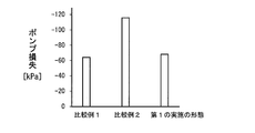
- FIG. 4 is a graph showing the magnitude of the pump loss.
- FIG. 5A is a PV diagram showing changes in cylinder volume and cylinder pressure of the 6-cycle engine according to the first embodiment.
- FIG. 5B is a PV diagram showing changes in cylinder volume and cylinder pressure of the 6-cycle engine according to Comparative Example 1.
- FIG. 5C is a PV diagram showing changes in cylinder volume and cylinder pressure of the 6-cycle engine according to Comparative Example 2.
- FIG. 6 is a graph showing the relationship between load and thermal efficiency.
- FIG. 7 is a time chart for explaining the operation method of the 6-cycle engine according to the second embodiment.
- FIG. 8 is a cross-sectional view of a cylinder head used in a 6-cycle engine according to the second embodiment.
- FIG. 9 is a time chart for explaining the operation method of the 6-cycle engine according to the third embodiment.
- FIG. 10 is a cross-sectional view of a cylinder head used in a 6-cycle engine according to the third embodiment.
- FIG. 11 is a cross-sectional view showing a configuration of a main part of a 6-cycle engine according to the fourth embodiment.
- FIG. 12 is a time chart for explaining the operation method of the 6-cycle engine according to the fourth embodiment.
- FIG. 13 is a cross-sectional view of a cylinder head used in a 6-cycle engine according to the fourth embodiment.
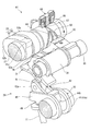
- FIG. 14 is a perspective view showing a configuration of a valve gear for a six-cycle engine according to the fourth embodiment. In FIG. 14, a part of the operation mode changing mechanism is cut away.
- FIG. 15A is a cross-sectional view of a first intake cam of a 6-cycle engine according to the fourth embodiment.
- FIG. 15B is a cross-sectional view of the second intake cam of the six-cycle engine according to the fourth embodiment.
- FIG. 16A is a cross-sectional view of a first exhaust cam of a 6-cycle engine according to the fourth embodiment.
- FIG. 16B is a cross-sectional view of the second exhaust cam of the six-cycle engine according to the fourth embodiment.
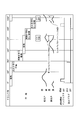
- FIG. 17 is a graph that is a map used to change the driving mode.
- the first embodiment is an embodiment of the invention described in claim 1, claim 2, claim 6 and claim 7.
- a 6-cycle engine 1 shown in FIG. 1 is for carrying out the operation method of the 6-cycle engine according to the present invention, and includes a cylinder 2, a piston 3, and a cylinder head 4.
- the 6-cycle engine 1 can be configured as a single cylinder engine or a multi-cylinder engine.
- the 6-cycle engine 1 can also be configured as an in-line multi-cylinder engine or a V-type engine.
- the cylinder 2 and the cylinder head 4 are cooled by a water-cooling type cooling device (not shown).
- the piston 3 is movably fitted in the cylinder 2 and reciprocates between the bottom dead center and the top dead center while being inserted into the cylinder 2.
- the cylinder head 4 forms a combustion chamber 5 in cooperation with the cylinder 2 and the piston 3 described above.
- the combustion chamber 5 is surrounded by the cylinder 2, the piston 3, and the cylinder head 4.
- an intake port 6 and an exhaust port 7 are formed in the cylinder head 4.
- a downstream end of the intake port 6 opens to the combustion chamber 5.
- the upstream side of the intake port 6 is connected to an intake device having a throttle valve (not shown).
- the upstream end of the exhaust port 7 opens into the combustion chamber 5.
- the downstream side of the exhaust port 7 is connected to an exhaust device having a catalyst (not shown).
- the cylinder head 4 includes an intake valve 11, an exhaust valve 12, a fuel injection injector 13, a spark plug 14, and a valve gear 15.
- the intake valve 11 opens and closes the intake port 6.
- the intake valve 11 is driven by a valve gear 15 described later.
- the exhaust valve 12 opens and closes the exhaust port 7.
- the exhaust valve 12 is driven by a valve gear 15 described later.
- the fuel injector 13 is at least one of a position indicated by a solid line between the spark plug 14 and the intake valve 11 in FIG. 1 and a position indicated by a two-dot chain line in the middle portion of the intake port 6 in FIG. It can be provided at one position.
- a fuel injection injector 13 indicated by a solid line in FIG. 1 directly injects fuel 16 into the combustion chamber 5.
- the fuel injector 13 that directly injects fuel into the combustion chamber 5 is simply referred to as an in-cylinder injector.
- a fuel injection injector 13 indicated by a two-dot chain line in FIG. 1 injects fuel into the intake port 6.
- the fuel injector 13 that injects fuel into the intake port 6 in this manner is hereinafter referred to as an intake port injector. That is, the six-cycle engine 1 according to this embodiment includes a fuel injection injector 13 that injects fuel into at least one of the combustion chamber 5 and the intake port 6. The timing at which the in-cylinder injector 13 and the intake port injector 13 inject fuel 16 is controlled by the engine controller 17.
- the spark plug 14 is attached to the center of the ceiling wall 5 a of the combustion chamber 5.
- the ceiling wall 5 a is formed in a circular shape when viewed from the axial direction of the cylinder 2.
- the ignition timing of the spark plug 14 is controlled by the control device 17.
- the valve gear 15 operates the intake valve 11 and the exhaust valve 12 so that six strokes described later are sequentially executed. As shown in FIG. 2, the six strokes are an intake stroke, a compression stroke with ignition, an expansion stroke with combustion, an exhaust stroke, an expansion stroke without combustion, and a compression stroke without ignition. is there.
- the piston 3 moves from the top dead center to the bottom dead center with the intake valve 11 open and the exhaust valve 12 closed, and fresh air is drawn into the cylinder 2.
- the movement of the piston 3 from the top dead center toward the bottom dead center is simply referred to as the piston 3 descending.
- the movement of the piston 3 from the bottom dead center toward the top dead center is simply referred to as the piston 3 rising.
- the intake stroke ends when the intake valve 11 is closed.
- the intake valve 11 is kept closed until it is opened by the valve gear 15 in an exhaust stroke described later.
- the in-cylinder injector 13 is provided as a fuel injector, the in-cylinder injector 13 directly injects the fuel 16 into the combustion chamber 5 during the intake stroke.
- FIG. 2 shows the fuel injection timing of the in-cylinder injector 13 with a thick line, and the fuel injection timing of the intake port injection injector 13 with a broken line.
- the piston 3 In the compression stroke that accompanies ignition, the piston 3 ascends while the intake valve 11 and the exhaust valve 12 are closed, and the air in the cylinder 2 is compressed.
- the above-described fuel injection injector 13 injects the fuel 16 in the compression stroke that accompanies this ignition.
- the spark plug 14 is energized at the end of this stroke to ignite the fuel 16.
- the piston 3 In the expansion stroke with combustion, the piston 3 is lowered by the combustion pressure while the intake valve 11 and the exhaust valve 12 are closed.
- the six-cycle engine according to this embodiment is characterized by an operation method from the latter half of the exhaust stroke to the first half of the expansion stroke without the next combustion.
- This 6-cycle engine operation method is an operation in which a valve overlap state in which both the intake valve 11 and the exhaust valve 12 are opened is realized during a period from the latter half of the exhaust stroke to the first half of the expansion stroke without combustion. Is the method.
- the valve operating device 15 is used when the exhaust stroke and the expansion stroke without combustion are performed, and when the piston 3 is located on the top dead center side, The valve 11 is opened for a predetermined period.
- the combustion starts when the position of the piston 3 exceeds 90 ° after the bottom dead center in the exhaust stroke.
- the valve overlap state is realized when shown as a period B in FIG.
- the piston 3 descends while the period of the valve overlap state ends and the intake valve 11 and the exhaust valve 12 are closed, and the air expands in the cylinder 2.
- the piston 3 rises with the intake valve 11 and the exhaust valve 12 closed, and the air that has been expanded in the cylinder 2 is restored.
- valve operating apparatus 15 in the valve operating apparatus 15 according to this embodiment, the valve overlap state is realized once within the period from the exhaust stroke to the intake stroke through the expansion stroke without combustion and the compression stroke without ignition.
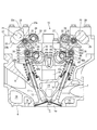
- the valve gear 15 for carrying out this 6-cycle engine operation method is formed as shown in FIG. 3, the same or equivalent members as described with reference to FIG. 1 are denoted with the same reference numerals, and detailed description thereof is omitted as appropriate.
- the intake port 6 and the exhaust port 7 of the cylinder head 4 are formed in a bifurcated shape inside the cylinder head 4. For this reason, two intake valves 11 and two exhaust valves 12 are provided for each cylinder.
- the intake camshaft 21 and the exhaust camshaft 22 each rotate once when a crankshaft (not shown) rotates three times.
- the rotation of the intake camshaft 21 is converted into a reciprocating motion by the intake cam 23 provided on the intake camshaft 21 and the intake valve transmission mechanism 24 and transmitted to the intake valve 11.
- the rotation of the exhaust camshaft 22 is converted into a reciprocating motion by an exhaust cam 25 provided on the exhaust camshaft 22 and an exhaust valve transmission mechanism 26 and transmitted to the exhaust valve 12.
- the rotation direction of the intake camshaft 21 according to this embodiment is clockwise in FIG.
- the intake camshaft 21 and the exhaust camshaft 22 are rotatably supported by a support member 27 and a cam cap 28, respectively.
- the support member 27 is attached to the cylinder head 4.
- the cam cap 28 is attached to the support member 27 so as to sandwich the intake cam shaft 21 and the exhaust cam shaft 22 together with the support member 27.
- the intake cam 23 of the intake cam shaft 21 is provided for each intake valve 11.
- An exhaust cam 25 of the exhaust cam shaft 22 is provided for each exhaust valve 12.
- the intake cam 23 is composed of a base circle portion 23a, a first nose portion 23b, and a second nose portion 23c.
- the base circle portion 23a is formed so that the intake valve 11 does not open.
- the first nose portion 23b is for performing an intake stroke.
- the 2nd nose part 23c is for implement
- the second nose portion 23c is formed with a smaller projecting dimension projecting from the base circle portion 23a and a smaller width in the rotational direction as compared with the first nose portion 23b.
- the intake valve transmission mechanism 24 converts the rotation of the intake cam 23 into a reciprocating motion and transmits it to the intake valve 11.
- the exhaust valve transmission mechanism 26 converts the rotation of the exhaust cam 25 into a reciprocating motion and transmits it to the exhaust valve 12.
- the exhaust valve transmission mechanism 26 differs from the intake valve transmission mechanism 24 only in that the target of driving is the exhaust valve 12.
- the other configuration of the exhaust valve transmission mechanism 26 is the same as that of the intake valve transmission mechanism 24.
- members having the same functions as those of the intake valve transmission mechanism 24 are denoted by the same reference numerals, and detailed description thereof is omitted as appropriate.
- the intake valve transmission mechanism 24 includes a swing cam 31 positioned in the vicinity of the intake cam shaft 21 and a rocker arm 32 positioned between the swing cam 31 and the intake valve 11.
- the swing cam 31 and the rocker arm 32 are provided for each intake valve 11.
- the swing cam 31 includes a swing cam body 34 that is swingably supported by a support shaft 33 that is parallel to the intake cam shaft 21, and a roller 35 that is rotatably attached to the swing cam body 34. ing.
- the support shaft 33 is provided at a position away from the intake cam shaft 21 toward the exhaust cam shaft 22 and is supported by the support member 27.
- a cam surface 36 that comes into contact with the rocker arm 32 described later is formed at the swing end of the swing cam main body 34.
- the cam surface 36 includes a base circle portion 36a and a lift portion 36b.
- the base circular portion 36 a is formed in an arc shape centered on the axis of the support shaft 33 when viewed from the axial direction of the intake cam shaft 21.
- the lift part 36b is formed such that the distance from the axis of the support shaft 33 gradually increases as the distance from the base circle part 36a increases.
- the roller 35 is attached to the swing cam body 34 so as to protrude from the swing cam body 34 toward the intake cam shaft 21 side.
- the axis of the roller 35 is parallel to the axis of the intake camshaft 21.
- the roller 35 rotates in contact with the intake cam 23.
- the swing cam 31 according to this embodiment is urged by a torsion coil spring 37 so that the roller 35 is always in contact with the intake cam 23.
- the torsion coil spring 37 is supported by the support shaft 33 in a state where the support shaft 33 penetrates.
- the rocker arm 32 is configured to transmit the swing motion of the swing cam 31 to the intake valve 11 by a plurality of swing members.
- the plurality of swing members are a control arm 42 having a roller 41 that contacts the cam surface 36 of the swing cam 31 and a rocker arm main body 43 that contacts the intake valve 11.
- the control arm 42 and the rocker arm main body 43 are swingably supported by the rocker shaft 44.
- the rocker shaft 44 is rotatably supported by the cylinder head 4 and the support member 27 in a state where the axis is parallel to the axis of the intake cam shaft 21.
- the rocker shaft 44 is formed in a so-called crankshaft shape. That is, the rocker shaft 44 includes a main shaft 44a located on the same axis as the portion supported by the cylinder head 4 and the support member 27, and an eccentric pin 44b located at an eccentric position with respect to the main shaft 44a.
- the rocker arm main body 43 is swingably supported by the main shaft 44a.
- the control arm 42 is swingably supported by the eccentric pin 44b.
- a drive mechanism such as a servomotor (not shown) is connected to one end of the rocker shaft 44.
- the rocker shaft 44 is rotated by a drive mechanism so as to have a predetermined rotation angle.
- the rocker arm main body 43 is formed with an arm 43 a that comes into contact with a control arm main body 42 a of the control arm 42 described later, and a pressing element 43 b for pressing the shim 45 of the intake valve 11.
- the control arm 42 includes a control arm main body 42a that is rotatably supported by the eccentric pin 44b, and a roller 41 that is rotatably provided at the swing end of the control arm main body 42a.
- the swing end portion of the control arm main body 42a is formed in a shape that comes into contact with the arm 43a of the rocker arm main body 43 from the upper side in FIG. As the rocker shaft 44 rotates and the position of the eccentric pin 44b changes, the control arm 42 moves in the longitudinal direction of the arm 43a.
- the expansion stroke without combustion and the compression stroke without ignition are performed after the exhaust stroke. For this reason, the period in which these strokes are performed becomes a cooling period, and cooling in the cylinder 2 is promoted.
- This cooling is performed using only the basic components of the 6-cycle engine 1.
- the intake cam shaft 21 rotates and the second nose portion 23c of the intake cam 23 pushes the roller 35, so that the second half of the exhaust stroke and the first half of the expansion stroke without combustion are performed.
- the valve overlap state is realized within the period. By realizing the valve overlap state in this way, the burned gas in the cylinder 2 is pushed out to the exhaust passage (exhaust port 7) by the intake air, and the gas in the cylinder 2 is exchanged.
- the gas exchange in the cylinder 2 is correctly performed, the thermal efficiency is increased, and a high cooling effect can be obtained by using only the engine components, and the operation of the 6-cycle engine.
- a method can be provided.
- the position of the piston 3 is 90 degrees after the top dead center in the expansion stroke without combustion after the position of the piston 3 exceeds 90 degrees after the bottom dead center in the exhaust stroke.
- the intake valve 11 is opened and closed so that the valve overlap state is realized within a period until the position of the degree is reached. For this reason, an expansion stroke without combustion and a compression stroke without ignition are carried out with no or little burned gas remaining in the cylinder 2, and the inside of the cylinder 2 is efficiently cooled. Is done. Therefore, according to this embodiment, since the cooling in the cylinder 2 is further promoted, it is possible to provide a 6-cycle engine and a 6-cycle engine operating method in which the thermal efficiency is further increased.
- Comparative Example 1 is a result when the intake valve is held in a closed state within a period from an exhaust stroke to an expansion stroke without combustion.
- Comparative Example 2 shows the result when the intake valve is opened while the exhaust valve is closed in the expansion stroke without combustion, and the exhaust valve is opened with the intake valve closed in the compression stroke without ignition. It is.
- the intake valve 11 is opened twice compared to Comparative Example 1 in which the intake valve is opened only in the intake stroke. Regardless, the increase in pumping loss is negligible. Further, by adopting this embodiment, the pumping loss is significantly smaller than that of the engine of the comparative example 2.
- FIG. 5A shows a relationship between the change in the cylinder volume (log V) and the change in the cylinder pressure (Log P) of the 6-cycle engine according to this embodiment
- FIG. 5B shows a PV diagram of the 6-cycle engine of Comparative Example 1
- FIG. 5C shows a PV diagram of the 6-cycle engine of Comparative Example 2.
- FIG. 5A although the cylinder volume increases at the beginning of the expansion stroke without combustion, there is little decrease in the cylinder pressure, and at this time, almost no pumping loss occurs. You can see that they are not.
- the 6-cycle engine 1 according to this embodiment When the 6-cycle engine 1 according to this embodiment was operated to obtain the thermal efficiency, the result shown in FIG. 6 was obtained.
- the thermal efficiency of the 6-cycle engine according to this embodiment is indicated by a solid line
- the thermal efficiency of the 6-cycle engine of Comparative Example 1 is indicated by a broken line.
- the 6-cycle engine according to this embodiment has a higher thermal efficiency in the entire operation region from the low load operation to the high load operation than the 6-cycle engine of Comparative Example 1.
- the 6-cycle engine and the operation method of the 6-cycle engine according to the present invention can be configured as shown in FIGS. 7 and 8, the same or equivalent members as those described with reference to FIGS. 1 to 6 are denoted by the same reference numerals, and detailed description thereof is omitted as appropriate.
- the second embodiment is an embodiment of the invention described in claims 3 and 8.
- the six-cycle engine and the operation method of the six-cycle engine according to this embodiment are different from the six-cycle engine in the case of adopting the first embodiment only in the operation of the intake valve 11 and the exhaust valve 12.
- the difference is that, as shown in FIG. 7, the exhaust valve 12 is opened and closed during the period from the compression stroke without ignition to the intake stroke. That is, in the operation method of the 6-cycle engine according to the second embodiment, both the intake valve 11 and the exhaust valve 12 are opened during the period from the second half of the compression stroke without ignition to the first half of the intake stroke.
- the valve gear 15 is used when a compression stroke without ignition and an intake stroke following this stroke are performed, and when the piston 3 is located on the top dead center side.
- the exhaust valve 12 that has been closed is opened for a predetermined period.
- the exhaust valve 12 opens before the intake valve 11.
- the position of the piston 3 exceeds 90 ° after the bottom dead center in the compression stroke without ignition. This is the period from the time until the position of the piston 3 reaches 90 degrees after top dead center in the intake stroke.
- the valve overlap state is realized when shown as a period D in FIG.
- the operation method of the 6-cycle engine according to this embodiment can be carried out by the valve gear 15 configured as shown in FIG.
- the valve operating device 15 shown in FIG. 8 is the same as the valve operating device 15 shown in FIG. 3 except that the shapes of the intake cam 23 and the exhaust cam 25 are different.
- the intake cam 23 according to this embodiment includes a base circle portion 23a and a first nose portion 23b.
- the exhaust cam 25 includes a base circle portion 25a, a first nose portion 25b, and a second nose portion 25c.
- the first nose portion 25b of the exhaust cam 25 is for performing an exhaust stroke.
- the second nose portion 25c of the exhaust cam 25 is for opening and closing the exhaust valve 12 during a period from the compression stroke without ignition to the intake stroke.
- the valve overlap state is realized during the period from the compression stroke without ignition to the intake stroke, so that the burned gas flows toward the exhaust passage in the cylinder 2. Inhalation is introduced. For this reason, when the intake air enters the cylinder 2, it is difficult to be blocked by the burned gas. Therefore, according to this embodiment, since the charging efficiency of intake air can be increased, it is possible to provide a 6-cycle engine and a method for operating the 6-cycle engine that further increase the thermal efficiency.
- the 6-cycle engine and the operation method of the 6-cycle engine according to the present invention can be configured as shown in FIGS. 9 and 10, members identical or equivalent to those described with reference to FIGS. 1 to 8 are given the same reference numerals, and detailed descriptions thereof are omitted as appropriate.
- the third embodiment is an embodiment of the invention described in claims 4 and 9.
- the 6-cycle engine and the operation method of the 6-cycle engine according to this embodiment have both the characteristics of the first embodiment and the characteristics of the second embodiment. ing. That is, the valve operating apparatus 15 according to this embodiment has a first valve overlap state and a second valve during the period from the exhaust stroke to the intake stroke through the expansion stroke without combustion and the compression stroke without ignition. A configuration in which the valve overlap state is realized is adopted.
- the position of the piston 3 is 90 degrees after the top dead center in the expansion stroke without combustion after the position of the piston 3 exceeds 90 degrees after the bottom dead center in the exhaust stroke. This is realized by opening and closing the intake valve 11 within a period until the position is reached.
- the position of the piston 3 is 90 degrees after the top dead center in the intake stroke after the position of the piston 3 exceeds 90 degrees after the bottom dead center in the compression stroke without ignition. This is realized by opening and closing the exhaust valve 12 within a period until the position is reached.
- the midway from the exhaust stroke to the expansion stroke without combustion and the midway from the compression stroke without ignition to the intake stroke In both cases, valve overlap is realized. For this reason, since the gas exchange in the cylinder 2 is performed twice during the cooling period between the exhaust stroke and the intake stroke, the amount of burned gas remaining in the cylinder 2 is further reduced. Therefore, according to this embodiment, it is possible to provide a 6-cycle engine with higher thermal efficiency and a method for operating the 6-cycle engine.
- the 6-cycle engine and the operation method of the 6-cycle engine according to the present invention can be configured as shown in FIGS. 11 to 17, members identical or equivalent to those described with reference to FIGS. 1 to 10 are given the same reference numerals, and detailed descriptions thereof are omitted as appropriate.
- the fourth embodiment is an embodiment of the invention described in claims 5 and 10.
- the valve operating device 15 of the six-cycle engine 1 can take at least one of the two operation modes.
- this valve gear 15 is provided with the driving
- the first operation mode is an operation mode in which the intake valve 11 opens and closes within a period from the exhaust stroke to the expansion stroke without combustion, as shown in FIG. More specifically, the first operation mode is an operation mode in which the intake valve 11 is opened and closed so that the valve overlap state is realized within a period indicated by a symbol A in FIG. Period A is from when the position of the piston 3 exceeds 90 degrees after bottom dead center in the exhaust stroke until the position of the piston 3 reaches 90 degrees after top dead center in the expansion stroke without combustion. It is a period.
- the second operation mode is an operation mode in which the exhaust valve 12 opens and closes within a range from a compression stroke without ignition to an intake stroke. More specifically, the second operation mode is an operation mode in which the exhaust valve 12 is opened and closed so that the valve overlap state is realized within a period indicated by a symbol C in FIG. Period C is from when the position of the piston 3 exceeds 90 degrees after the bottom dead center in the compression stroke without ignition until the position of the piston 3 reaches 90 degrees after the top dead center in the intake stroke. It is a period.
- the operation mode change mechanism 51 is a first operation mode, a second operation mode, and an operation mode in which the first operation mode and the second operation mode are simultaneously realized (hereinafter, this operation mode is simply referred to as a first mode). 3) is switched based on the operating state of the 6-cycle engine 1.
- the driving mode changing mechanism 51 according to this embodiment switches the driving mode based on the engine speed and the load.
- the rotational speed of the engine can be obtained by calculating the rotational angle of a camshaft or crankshaft (not shown) with a sensor (not shown). Further, the rotational speed of the engine can also be obtained by calculation based on the energization interval of the spark plug 14.
- the engine load can be obtained by calculation based on the opening of a throttle valve (not shown) provided in the intake passage, for example. These calculations are performed by the control device 17. Further, the switching operation of the operation mode changing mechanism 51 is controlled by the control device 17.
- the control device 17 controls the switching operation of the operation mode changing mechanism 51 based on the map shown in FIG.
- the map shown in FIG. 17 is obtained by assigning the type of operation mode to be switched to the engine rotation speed and the load.
- a first boundary line indicated by a broken line, a second boundary line indicated by a solid line, and a third boundary line indicated by a two-dot chain line are drawn.
- the first boundary line separates a region A in which the second operation mode is selected and a region B in which the above-described third operation mode is selected.
- the second boundary line separates the region B and the region C where the first operation mode is selected.
- the third boundary line defines the rotational speed and load that are the limits of the region C in which the first operation mode is selected.
- the first boundary line is drawn in a parabolic shape passing through the origin of FIG. 17 and the first rotation speed V1.
- the vertex of the first boundary line is located at a coordinate at which the rotational speed is a rotational speed V2 that is approximately 1 ⁇ 2 of the first rotational speed V1 and the load is the first load value L1.
- the second boundary line is drawn in a parabolic shape passing through the origin of FIG. 17 and the second rotation speed V3 higher than the first rotation speed V1.
- the vertex of the second boundary line is located at the coordinates where the rotation speed is equal to the first rotation speed V1 and the load becomes the second load value L2.
- the third boundary line indicates the rotation speed and load value at which operation is possible, and is drawn in a parabolic shape passing through the origin of FIG.
- the vertex of the third boundary line is a coordinate at which the engine speed is the fourth rotation speed V4 higher than the third rotation speed V3 and the load becomes the third load value L3 higher than the second load value L2. Is located.
- the rotation speed and load for switching the operation mode are not limited to the rotation speed and load shown in this map, and can be changed as appropriate according to the engine displacement and the output level.
- the second operation mode is adopted.
- the third operation mode is adopted.
- the rotational speed of the engine is higher than the third rotational speed V3 and the load is lower than the second load value L2
- the first operation mode is adopted.
- the operation mode changing mechanism 51 for implementing the operation method of the 6-cycle engine for switching a plurality of operation modes as described above is formed as shown in FIGS. 13 to 16, members identical or equivalent to those described with reference to FIGS. 1 and 3 are given the same reference numerals, and detailed description thereof is omitted as appropriate.
- the intake cam 23 of the valve gear 15 according to this embodiment is constituted by a first intake cam 52 and a second intake cam 53, as shown in FIGS. 14, 15A and 15B.
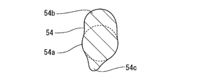
- the exhaust cam 25 is comprised by the 1st exhaust cam 54 and the 2nd exhaust cam 55, as shown to FIG. 16A and FIG. 16B.
- the first intake cam 52 is the same as that shown in FIGS. 3 and 10, and as shown in FIG. 15A, the base circle portion 52a, the first nose portion 52b, and the second nose portion 52c. And is composed of.
- the second intake cam 53 is obtained by removing the second nose 52c portion from the first intake cam 52, and includes a base circle portion 53a and a nose portion 53b as shown in FIG. 15B.
- the first intake cam 52 and the second intake cam 53 are arranged in a state in which the rotation phases of the first nose portion 52b and the nose portion 53b coincide with each other and are adjacent to each other in the axial direction of the intake cam shaft 21. It has been.
- the first exhaust cam 54 is the same as that shown in FIGS. 8 and 10, and as shown in FIG. 16A, the base circle portion 54a, the first nose portion 54b, and the second nose portion 54c. And is composed of.
- the second exhaust cam 55 is obtained by removing the second nose 54c portion from the first exhaust cam 54, and includes a base circular portion 55a and a nose portion 55b as shown in FIG. 16B.
- the first exhaust cam 54 and the second exhaust cam 55 are arranged in a state in which the rotation phases of the first nose portion 54 b and the nose portion 55 b coincide with each other and are adjacent to each other in the axial direction of the exhaust cam shaft 22. It has been.
- the swing cam 31 on the intake cam shaft 21 side and the swing cam 31 on the exhaust cam shaft 22 side in the valve operating device 15 are supported by the support member 27 so as to be movable in the axial direction together with the support shaft 33.
- the cam surfaces 36 of the swing cams 31 are formed long in the axial direction of the cam shaft. The length in the axial direction is formed such that the state in which the swing cam 31 is in contact with the rocker arm 32 is maintained even if the swing cam 31 moves in the axial direction.
- an operation mode changing mechanism 51 includes an intake side switching unit 61 provided on the intake cam shaft 21 side, and an exhaust side switching unit 62 provided on the exhaust cam shaft 22 side. It has.
- the intake side switching unit 61 is for switching between a form in which the first intake cam 52 drives the intake valve 11 and a form in which the second intake cam 53 drives the intake valve 11.
- the exhaust side switching unit 62 is for switching between a form in which the first exhaust cam 54 drives the exhaust valve 12 and a form in which the second exhaust cam 55 drives the exhaust valve 12.
- the intake side switching unit 61 and the exhaust side switching unit 62 have the same structure. Therefore, in the following, the intake side switching unit 61 will be described, and the exhaust side switching unit 62 will be denoted by the same reference numeral, and detailed description thereof will be omitted.
- the intake side switching unit 61 has a structure that reciprocates the swing cam 31 by converting the rotation of the intake cam shaft 21 into a reciprocating motion.
- the first cam groove 63 and the second cam groove 64 formed in the intake camshaft 21, and these cam grooves 63 , 64, and a slider 68 having these cam grooves 63, 64 and two pins 66, 67 inserted into the annular groove 65 are used.
- the slider 68 is connected to the support shaft 33 that supports the swing cam 31 so as to move integrally.
- the two pins 66 and 67 are connected to an actuator 69 (see FIG. 13).
- the actuator 69 has a cam groove 63 so that when one pin 66 (67) enters the cam grooves 63, 64 and the annular groove 65, the other pin 67 (66) exits from the cam grooves 63, 64 and the annular groove 65. , 64 and the annular groove 65, two pins 66, 67 are alternately put in and out.
- the first cam groove 63 and the second cam groove 64 are inclined in one axial direction and the other axial direction with respect to the rotation direction of the intake cam shaft 21 in order to generate thrust in one axial direction and the other in the axial direction. It is formed in a state, and is connected to the annular groove 65 at the downstream end in the rotational direction.
- the first pin 66 passes through the first cam groove 63 and enters the annular groove 65, so that the slider 68 moves to the lower left side in FIG. 35 contacts the first intake cam 52.
- the second pin 67 passes through the second cam groove 64 and enters the annular groove 65, the slider 68 moves to the upper right side in FIG. 14 together with the swing cam 31, and the roller 35 moves to the second intake cam. 53 is contacted.
- the distance in the axial direction along which the slider 68 moves varies between the position where the roller 35 of the swing cam 31 contacts the first intake cam 52 and the position where the roller 35 contacts the second intake cam 53. This corresponds to the distance that the moving cam 31 moves. That is, when the swing cam 31 moves together with the slider 68, the form in which the first intake cam 52 is used and the form in which the second intake cam 53 is used are switched.
- the switching of the intake cam 23 by the reciprocating movement of the swing cam 31 is performed when the intake valve 11 is closed, that is, when the roller 35 contacts the base circular portions 52a and 53a.
- the exhaust cam 25 is switched when the exhaust valve 12 is closed (when the roller 35 contacts the base circular portions 54a and 55a).
- the first operation mode described above is realized by using the first intake cam 52 and the second exhaust cam 55.
- the second operation mode is realized by using the second intake cam 53 and the first exhaust cam 54.
- the third operation mode is realized by using the first intake cam 52 and the first exhaust cam 54.
- the valve gear 15 according to this embodiment adopts at least one of the first operation mode and the second operation mode based on the rotational speed and load of the engine. For this reason, according to this embodiment, since the valve overlap state is realized at a time suitable for the operating state of the engine, a 6-cycle engine capable of performing gas exchange in the cylinder 2 more efficiently and A method for operating a six-cycle engine can be provided.
Abstract
Priority Applications (3)
| Application Number | Priority Date | Filing Date | Title |
|---|---|---|---|
| EP14823775.3A EP3020944A4 (fr) | 2013-07-09 | 2014-06-20 | Moteur à six temps et procédé pour faire fonctionner un moteur à six temps |
| US14/902,691 US9945296B2 (en) | 2013-07-09 | 2014-06-20 | Six-stroke engine and method of operating six-stroke engine |
| JP2015526239A JPWO2015005097A1 (ja) | 2013-07-09 | 2014-06-20 | 6サイクルエンジンおよび6サイクルエンジンの運転方法 |
Applications Claiming Priority (2)
| Application Number | Priority Date | Filing Date | Title |
|---|---|---|---|
| JP2013-143253 | 2013-07-09 | ||
| JP2013143253 | 2013-07-09 |
Publications (1)
| Publication Number | Publication Date |
|---|---|
| WO2015005097A1 true WO2015005097A1 (fr) | 2015-01-15 |
Family
ID=52279783
Family Applications (1)
| Application Number | Title | Priority Date | Filing Date |
|---|---|---|---|
| PCT/JP2014/066394 WO2015005097A1 (fr) | 2013-07-09 | 2014-06-20 | Moteur à six temps et procédé pour faire fonctionner un moteur à six temps |
Country Status (4)
| Country | Link |
|---|---|
| US (1) | US9945296B2 (fr) |
| EP (1) | EP3020944A4 (fr) |
| JP (1) | JPWO2015005097A1 (fr) |
| WO (1) | WO2015005097A1 (fr) |
Families Citing this family (6)
| Publication number | Priority date | Publication date | Assignee | Title |
|---|---|---|---|---|
| WO2018067543A1 (fr) * | 2016-10-07 | 2018-04-12 | Cummins Inc. | Systèmes et procédés de dosage de carburant dans le cylindre pour gestion thermique de système de post-traitement des gaz d'échappement |
| US10221779B2 (en) | 2016-12-16 | 2019-03-05 | Ford Global Technologies, Llc | System and method for providing EGR to an engine |
| US10138805B2 (en) * | 2017-03-03 | 2018-11-27 | Chi Keng Chen | Six-stroke and eight-stroke internal combustion engines |
| DE102017208788A1 (de) * | 2017-05-24 | 2018-11-29 | Robert Bosch Gmbh | Verfahren und Vorrichtung zum Betreiben eines fremdgezündeten Verbrennungsmotors |
| GB201717438D0 (en) | 2017-10-24 | 2017-12-06 | Rolls Royce Plc | Apparatus amd methods for controlling reciprocating internal combustion engines |
| GB201717437D0 (en) | 2017-10-24 | 2017-12-06 | Rolls Royce Plc | Apparatus and methods for controlling reciprocating internal combustion engines |
Citations (4)
| Publication number | Priority date | Publication date | Assignee | Title |
|---|---|---|---|---|
| JPH062558A (ja) * | 1992-06-16 | 1994-01-11 | Mazda Motor Corp | 気体燃料エンジン |
| JP2000170559A (ja) * | 1998-12-02 | 2000-06-20 | Mitsubishi Motors Corp | 6サイクル内燃機関 |
| JP2007303303A (ja) | 2006-05-09 | 2007-11-22 | Sgg Kenkyusho:Kk | 6行程ガソリンエンジン |
| JP2010209683A (ja) * | 2009-03-06 | 2010-09-24 | Toyota Motor Corp | 内燃機関の制御装置 |
Family Cites Families (6)
| Publication number | Priority date | Publication date | Assignee | Title |
|---|---|---|---|---|
| US20030226524A1 (en) * | 2002-06-10 | 2003-12-11 | Alireza Ziabazmi | Bazmi's six stroke engine |
| US6789513B2 (en) * | 2002-06-10 | 2004-09-14 | Alireza Ziabazmi | Bazmi's six-stroke engine with intake-exhaust valves |
| JP2007224908A (ja) * | 2006-02-20 | 2007-09-06 | Robert Bosch Gmbh | 内燃機関の運転方法 |
| US8291872B2 (en) * | 2009-06-12 | 2012-10-23 | Ut-Battelle, Llc | Highly efficient 6-stroke engine cycle with water injection |
| EP2808516A4 (fr) * | 2012-01-27 | 2014-12-03 | Yamaha Motor Co Ltd | Moteur à six temps comprenant une course de balayage |
| EP2808517A1 (fr) * | 2012-01-27 | 2014-12-03 | Yamaha Hatsudoki Kabushiki Kaisha | Moteur à six temps comprenant une course de balayage |
-
2014
- 2014-06-20 JP JP2015526239A patent/JPWO2015005097A1/ja active Pending
- 2014-06-20 EP EP14823775.3A patent/EP3020944A4/fr not_active Withdrawn
- 2014-06-20 WO PCT/JP2014/066394 patent/WO2015005097A1/fr active Application Filing
- 2014-06-20 US US14/902,691 patent/US9945296B2/en not_active Expired - Fee Related
Patent Citations (4)
| Publication number | Priority date | Publication date | Assignee | Title |
|---|---|---|---|---|
| JPH062558A (ja) * | 1992-06-16 | 1994-01-11 | Mazda Motor Corp | 気体燃料エンジン |
| JP2000170559A (ja) * | 1998-12-02 | 2000-06-20 | Mitsubishi Motors Corp | 6サイクル内燃機関 |
| JP2007303303A (ja) | 2006-05-09 | 2007-11-22 | Sgg Kenkyusho:Kk | 6行程ガソリンエンジン |
| JP2010209683A (ja) * | 2009-03-06 | 2010-09-24 | Toyota Motor Corp | 内燃機関の制御装置 |
Non-Patent Citations (1)
| Title |
|---|
| See also references of EP3020944A4 |
Also Published As
| Publication number | Publication date |
|---|---|
| EP3020944A4 (fr) | 2016-07-06 |
| US20160169125A1 (en) | 2016-06-16 |
| JPWO2015005097A1 (ja) | 2017-03-02 |
| EP3020944A1 (fr) | 2016-05-18 |
| US9945296B2 (en) | 2018-04-17 |
Similar Documents
| Publication | Publication Date | Title |
|---|---|---|
| WO2015005097A1 (fr) | Moteur à six temps et procédé pour faire fonctionner un moteur à six temps | |
| JP4314595B2 (ja) | 6サイクル機関の排気触媒制御 | |
| US8863706B2 (en) | Four-stroke cycle engine | |
| JP5248118B2 (ja) | 高圧蒸気機関及び圧縮ガスモータ用バルブ及び補助排気システム | |
| US6918363B2 (en) | Valve drive apparatus of internal-combustion engine | |
| US20110197834A1 (en) | Early intake valve closing and variable valve timing assembly and method | |
| JP6742793B2 (ja) | 内燃機関 | |
| JP5580480B2 (ja) | 6サイクルエンジン | |
| US9091204B2 (en) | Internal combustion engine having piston with piston valve and associated method | |
| JP2012219708A (ja) | 可変圧縮比エンジン | |
| JP2008128227A (ja) | 超高効率4サイクル内燃機関 | |
| JP5826294B2 (ja) | 掃気行程を有する6サイクルエンジン | |
| US20190093571A1 (en) | Engine control device | |
| JP2007263050A (ja) | 内燃機関 | |
| KR100885464B1 (ko) | 4행정 내연기관의 흡배기 장치 | |
| JP2014234821A (ja) | 集中型燃焼室による超高効内燃機関 | |
| WO2015013141A1 (fr) | Moteur à combustion interne à six temps et procédé pour le faire fonctionner | |
| JP7220032B2 (ja) | レシプロ式内燃機関の吸排気装置 | |
| JP6323909B2 (ja) | エンジン | |
| JP2018017164A (ja) | 内燃機関の制御装置 | |
| JP2017155620A (ja) | 可変サイクルエンジン | |
| JP2006220121A (ja) | 内燃機関のシリンダヘッド | |
| CN103233789A (zh) | 应用二冲程阿特金森循环的多模全顶置气门二冲程内燃机 | |
| US20220220906A1 (en) | Valve control apparatus for engine | |
| US7047920B2 (en) | Engine valve actuation system and method for controlling white smoke |
Legal Events
| Date | Code | Title | Description |
|---|---|---|---|
| 121 | Ep: the epo has been informed by wipo that ep was designated in this application |
Ref document number: 14823775 Country of ref document: EP Kind code of ref document: A1 |
|
| ENP | Entry into the national phase |
Ref document number: 2015526239 Country of ref document: JP Kind code of ref document: A |
|
| WWE | Wipo information: entry into national phase |
Ref document number: 14902691 Country of ref document: US |
|
| WWE | Wipo information: entry into national phase |
Ref document number: 2014823775 Country of ref document: EP |
|
| NENP | Non-entry into the national phase |
Ref country code: DE |