WO2015001971A1 - ポリカーボネート樹脂組成物およびポリカーボネート樹脂組成物を用いた蛍光検出分析基板 - Google Patents
ポリカーボネート樹脂組成物およびポリカーボネート樹脂組成物を用いた蛍光検出分析基板 Download PDFInfo
- Publication number
- WO2015001971A1 WO2015001971A1 PCT/JP2014/066274 JP2014066274W WO2015001971A1 WO 2015001971 A1 WO2015001971 A1 WO 2015001971A1 JP 2014066274 W JP2014066274 W JP 2014066274W WO 2015001971 A1 WO2015001971 A1 WO 2015001971A1
- Authority
- WO
- WIPO (PCT)
- Prior art keywords
- polycarbonate resin
- fluorescence detection
- analysis substrate
- fluorescence
- granule
- Prior art date
- Legal status (The legal status is an assumption and is not a legal conclusion. Google has not performed a legal analysis and makes no representation as to the accuracy of the status listed.)
- Ceased
Links
Images



Classifications
-
- C—CHEMISTRY; METALLURGY
- C08—ORGANIC MACROMOLECULAR COMPOUNDS; THEIR PREPARATION OR CHEMICAL WORKING-UP; COMPOSITIONS BASED THEREON
- C08G—MACROMOLECULAR COMPOUNDS OBTAINED OTHERWISE THAN BY REACTIONS ONLY INVOLVING UNSATURATED CARBON-TO-CARBON BONDS
- C08G64/00—Macromolecular compounds obtained by reactions forming a carbonic ester link in the main chain of the macromolecule
- C08G64/04—Aromatic polycarbonates
- C08G64/06—Aromatic polycarbonates not containing aliphatic unsaturation
-
- C—CHEMISTRY; METALLURGY
- C08—ORGANIC MACROMOLECULAR COMPOUNDS; THEIR PREPARATION OR CHEMICAL WORKING-UP; COMPOSITIONS BASED THEREON
- C08G—MACROMOLECULAR COMPOUNDS OBTAINED OTHERWISE THAN BY REACTIONS ONLY INVOLVING UNSATURATED CARBON-TO-CARBON BONDS
- C08G64/00—Macromolecular compounds obtained by reactions forming a carbonic ester link in the main chain of the macromolecule
- C08G64/20—General preparatory processes
- C08G64/22—General preparatory processes using carbonyl halides
- C08G64/24—General preparatory processes using carbonyl halides and phenols
-
- G—PHYSICS
- G01—MEASURING; TESTING
- G01N—INVESTIGATING OR ANALYSING MATERIALS BY DETERMINING THEIR CHEMICAL OR PHYSICAL PROPERTIES
- G01N33/00—Investigating or analysing materials by specific methods not covered by groups G01N1/00 - G01N31/00
- G01N33/48—Biological material, e.g. blood, urine; Haemocytometers
- G01N33/50—Chemical analysis of biological material, e.g. blood, urine; Testing involving biospecific ligand binding methods; Immunological testing
- G01N33/58—Chemical analysis of biological material, e.g. blood, urine; Testing involving biospecific ligand binding methods; Immunological testing involving labelled substances
- G01N33/582—Chemical analysis of biological material, e.g. blood, urine; Testing involving biospecific ligand binding methods; Immunological testing involving labelled substances with fluorescent label
-
- G—PHYSICS
- G01—MEASURING; TESTING
- G01N—INVESTIGATING OR ANALYSING MATERIALS BY DETERMINING THEIR CHEMICAL OR PHYSICAL PROPERTIES
- G01N33/00—Investigating or analysing materials by specific methods not covered by groups G01N1/00 - G01N31/00
- G01N33/48—Biological material, e.g. blood, urine; Haemocytometers
- G01N33/50—Chemical analysis of biological material, e.g. blood, urine; Testing involving biospecific ligand binding methods; Immunological testing
- G01N33/58—Chemical analysis of biological material, e.g. blood, urine; Testing involving biospecific ligand binding methods; Immunological testing involving labelled substances
- G01N33/585—Chemical analysis of biological material, e.g. blood, urine; Testing involving biospecific ligand binding methods; Immunological testing involving labelled substances with a particulate label, e.g. coloured latex
-
- B—PERFORMING OPERATIONS; TRANSPORTING
- B29—WORKING OF PLASTICS; WORKING OF SUBSTANCES IN A PLASTIC STATE IN GENERAL
- B29C—SHAPING OR JOINING OF PLASTICS; SHAPING OF MATERIAL IN A PLASTIC STATE, NOT OTHERWISE PROVIDED FOR; AFTER-TREATMENT OF THE SHAPED PRODUCTS, e.g. REPAIRING
- B29C45/00—Injection moulding, i.e. forcing the required volume of moulding material through a nozzle into a closed mould; Apparatus therefor
- B29C45/0001—Injection moulding, i.e. forcing the required volume of moulding material through a nozzle into a closed mould; Apparatus therefor characterised by the choice of material
-
- B—PERFORMING OPERATIONS; TRANSPORTING
- B29—WORKING OF PLASTICS; WORKING OF SUBSTANCES IN A PLASTIC STATE IN GENERAL
- B29K—INDEXING SCHEME ASSOCIATED WITH SUBCLASSES B29B, B29C OR B29D, RELATING TO MOULDING MATERIALS OR TO MATERIALS FOR MOULDS, REINFORCEMENTS, FILLERS OR PREFORMED PARTS, e.g. INSERTS
- B29K2069/00—Use of PC, i.e. polycarbonates or derivatives thereof, as moulding material
-
- B—PERFORMING OPERATIONS; TRANSPORTING
- B29—WORKING OF PLASTICS; WORKING OF SUBSTANCES IN A PLASTIC STATE IN GENERAL
- B29K—INDEXING SCHEME ASSOCIATED WITH SUBCLASSES B29B, B29C OR B29D, RELATING TO MOULDING MATERIALS OR TO MATERIALS FOR MOULDS, REINFORCEMENTS, FILLERS OR PREFORMED PARTS, e.g. INSERTS
- B29K2995/00—Properties of moulding materials, reinforcements, fillers, preformed parts or moulds
- B29K2995/0018—Properties of moulding materials, reinforcements, fillers, preformed parts or moulds having particular optical properties, e.g. fluorescent or phosphorescent
Definitions
- the present invention relates to a polycarbonate resin composition for a fluorescence detection / analysis substrate and a fluorescence detection / analysis substrate using the same.
- a fluorescent substance can be labeled on DNA, which is a target biomolecule, and irradiated with a laser beam or the like to excite the fluorescent substance, and the generated fluorescence can be read to analyze the gene.
- the fluorescence of this labeled fluorescent substance is very weak. For this reason, glass or silicon having low autofluorescence is often used as a base material for a fluorescence detection / analysis substrate used for gene analysis as described above.
- the substrate for the fluorescence detection and analysis substrate is transparent, excellent in workability, excellent in chemical resistance, excellent in heat resistance, and at low cost. It is required that production is possible.
- glass is used as the base material of the fluorescence detection analysis substrate, there are problems such as poor processability and high production costs.
- silicon is used, etching technology and photolithography technology are problematic. Therefore, processing is easy, but there is a problem in that transparency is poor.
- the plastic used for the substrate (support) for fluorescence detection is generally preferably transparent from the viewpoint of detection sensitivity.
- aromatic polycarbonate resin, polystyrene resin, saturated cyclic olefin resin, acrylic Resins are being studied.
- the fluorescence detection method as described above if the fluorescence derived from the substrate (autofluorescence) is large, the background of the substrate becomes high at the time of detection, and the detection accuracy decreases due to a decrease in the S / N ratio.
- As a material for the analysis substrate it is important to use a material having low autofluorescence.
- Aromatic polycarbonate resins are used in various fields such as compact discs, liquid crystal light guide plates, and light diffusion plates because of their excellent transparency, heat resistance, and transferability. For this reason, attempts have been made to use aromatic polycarbonate as a fluorescence detection and analysis substrate (see, for example, Patent Document 1).
- aromatic polycarbonate since aromatic polycarbonate has an aromatic ring, it is characterized by potentially high autofluorescence compared to other transparent resins.
- a material for the fluorescence detection / analysis substrate a material having a low autofluorescence (low background) in the visible light region wavelength (400 nm to 750 nm) is required, whereas an aromatic polycarbonate resin is Since it has autofluorescence in the visible light region wavelength, there is a problem that the background becomes high and is not suitable for use.
- JP 2002-14100 A JP 2001-231556 A JP 2005-179410 A Japanese Patent No. 4903518
- the biochip is sometimes processed at a high temperature during the handling process, and the heat resistance of the resin used for the substrate is required.
- the substrate is processed at 95 ° C.
- autoclave sterilization it may be processed at a high temperature of about 120 ° C.
- an analysis substrate that is devised to reduce the autofluorescence intensity of the aromatic polycarbonate with an additive or the like.
- the fall of fluorescence intensity is implement
- the substrate is excited by light that cannot be absorbed by the ultraviolet absorber or the like and emits light, and the performance as a fluorescence detection / analysis substrate is not satisfied.
- aromatic polycarbonate has excellent transparency, heat resistance, transferability, and other properties, but has a problem of large potential autofluorescence, and an effective autofluorescence reduction method has not yet been found.
- the development of a material suitable for a fluorescence detection / analysis substrate having excellent characteristics such as transparency, heat resistance, and transferability and having low autofluorescence has been desired.
- An object of the present invention is in view of the above-described circumstances, and an aromatic polycarbonate resin composition for a fluorescence detection / analysis substrate, in which autofluorescence is remarkably reduced and heat resistance and transparency are excellent, and this An object of the present invention is to provide a fluorescence detection / analysis substrate obtained by melt-molding.
- the present inventors diligently studied the autofluorescence possessed by the aromatic polycarbonate resin from the viewpoint of specifying the origin structure and the mechanism of generation / increase. As a result, it was found that the cause of autofluorescence emitted from aromatic polycarbonate resin was various branched structures generated by heat applied in the process of molding, etc., and the amount of the branched structure (the amount of autofluorescence) It has been found that it is greatly influenced by the additive and the kind of aromatic polycarbonate resin.
- the content of the compound described in detail later can be kept low, and as a result, branching in the polycarbonate resin selected granules It has been found that the amount of structure can be reduced.
- the transparent molded body obtained by, for example, injection molding of the selected granule has strong autofluorescence characteristic of polycarbonate resin having a fluorescence wavelength of around 310 nm, but the wavelength range of autofluorescence emission is extremely narrow, 400 nm to 700 nm. It was found that the autofluorescence in the visible light region was extremely low.
- the present invention is as follows.
- (I) In a fluorescence emission containing a polycarbonate resin synthesized by an interfacial polymerization method and excited by light having a wavelength of 290 nm, the fluorescence emission intensities at wavelengths of 310 nm, 400 nm, and 450 nm are respectively F (310) and F (400 ), F (450), a polycarbonate resin composition satisfying the following formula (1).
- (II) A fluorescent detection / analysis substrate made of polycarbonate resin containing the polycarbonate resin composition according to (I) above.
- the polycarbonate resin obtained by the interfacial polymerization method is a granular material, and is produced by a melt molding step of the granular material, according to any one of (II) to (IV) above Fluorescent detection analysis board made of polycarbonate resin.
- the fluorescence detection analysis board made from polycarbonate resin as described in (V).
- (X) The fluorescence detection made of polycarbonate resin according to the above (VII) or (VIII), which is manufactured using the selected granule obtained from the powder granule using a sieve in the granule sorting step Analysis board.
- (XI) The fluorescence detection analysis substrate made of polycarbonate resin according to the above (IX) or (X), which is manufactured using the selected granule obtained by removing the fine powder while vibrating the sieve .
- (XII) The fluorescence detection analysis substrate made of polycarbonate resin according to any one of (IX) to (XI), manufactured using the selected granule having a solution YI value of 1.30 or less.
- (XIII) The polycarbonate resin-made fluorescence detection / analysis board according to any one of (V) to (XII), which is produced by the polycarbonate powder having been dried before melt molding and having a water content of 200 ppm or less.
- (XIV) From the above (V) to (XIII), which is produced by melt-molding the selected granule in an atmosphere having an oxygen concentration of 10,000 ppm or less by addition of an inert gas and / or reduced pressure in the melt-molding step A fluorescent detection analysis substrate made of polycarbonate resin according to any one of the above.
- (XV) The fluorescence detection analysis substrate made of polycarbonate resin according to any one of (V) to (XIV), wherein the melt molding step is an injection molding step.
- the self-fluorescence in the visible light region of the aromatic polycarbonate resin which has been conventionally avoided as a resin for fluorescence detection and analysis substrate, is remarkably achieved by the present invention. Can be reduced. Therefore, according to the present invention, it is possible to provide an aromatic polycarbonate resin composition and a fluorescence detection / analysis substrate for a fluorescence detection / analysis substrate that have low autofluorescence, low background, and excellent heat resistance and transparency. it can.
- the aromatic polycarbonate resin composition for a fluorescence detection analysis substrate of the present invention and the fluorescence detection analysis substrate are a fluorescence detection analysis substrate in the fields of biochemistry, medical diagnosis, drug discovery, microbiological examination, food, environment, healthcare, etc.
- DNA microarrays protein chips (protein chips, protein arrays), enzyme chips, antigen chips, antibody chips, cell chips, biochips such as microbial chips, and flow paths, reaction fields, It can be widely used for applications such as reaction chips using Lab-on-a-chip, MEMS (MicroElectro Mechanical Systems), etc., in which the detection unit is integrated in a small size.
- the selected particles from which fine powder has been removed are obtained (particle selecting step), and the selected particles are injection molded to produce an injection molded product.
- injection molding process The auto-fluorescence at a wavelength in the visible light region is very small in a molded product such as the injection molded product.
- an injection-molded article of a polycarbonate resin in which the total content of the compounds represented by the above formulas (A) and (B) in the decomposition product after alkali hydrolysis is 5 ppm by weight or less, can be produced. .
- polycarbonate resin granules are produced by an interfacial polymerization method.
- the polycarbonate resin includes an aromatic dihydroxy compound or a small amount of a polyhydroxy compound, carbonyl chloride generally known as phosgene, or a carbonic acid diester represented by dimethyl carbonate or diphenyl carbonate, carbon monoxide. It can be obtained by reacting carbonyl compounds such as carbon dioxide and carbon dioxide.
- the polycarbonate resin in the present invention is a polymer or copolymer of a thermoplastic aromatic polycarbonate which may be linear or branched as long as the effects of the present invention are not lost.
- the pH is usually kept at 10 or more, an aromatic dihydroxy compound and a molecular weight modifier (terminal terminator), and if necessary aromatic An antioxidant for preventing oxidation of the group dihydroxy compound is used.
- a polymerization catalyst such as a tertiary amine or a quaternary ammonium salt is added, and interfacial polymerization is performed to produce a polycarbonate resin.
- the timing of adding the molecular weight regulator is not particularly limited as long as it is between the time of phosgenation and the start of the polymerization reaction.
- the reaction temperature is, for example, 0 to 35 ° C., and the reaction time is, for example, several minutes to several hours.
- Examples of the organic solvent inert to the reaction include chlorinated hydrocarbons such as dichloromethane, 1,2-dichloroethane, chloroform, monochlorobenzene and dichlorobenzene, and aromatic hydrocarbons such as benzene, toluene and xylene.
- Examples of the molecular weight regulator or terminal terminator include compounds having a monovalent phenolic hydroxyl group. Specific examples include m-methylphenol, p-methylphenol, m-propylphenol, p-propylphenol, p -Tert-butylphenol, p-long chain alkyl-substituted phenol and the like.
- tertiary amines such as trimethylamine, triethylamine, tributylamine, tripropylamine, trihexylamine, pyridine; quaternary ammonium salts such as trimethylbenzylammonium chloride, tetramethylammonium chloride, triethylbenzylammonium chloride, etc. Can be mentioned.
- Polycarbonate resin particles are produced, for example, by the following method.
- a dichloromethane solution containing a polycarbonate resin obtained by the interfacial polymerization method is dropped into warm water kept at about 45 ° C., and the solvent is removed by evaporation. Or it produces
- a polycarbonate resin flake is also produced by stirring and grinding a dichloromethane solution containing a polycarbonate resin by an interfacial polymerization method at about 40 ° C. while stirring with a kneader, and then removing the solvent with hot water of 95 ° C. or higher. be able to.
- the polycarbonate resin particles thus produced have, for example, average particle diameters of 50 to 300 ⁇ m, 300 to 500 ⁇ m, 500 to 700 ⁇ m, and 700 to 900 ⁇ m, such as 600 ⁇ m and 800 ⁇ m.
- the particle size distribution of the powder is 50-1500 ⁇ m, 100-1500 ⁇ m, 200-1500 ⁇ m, 300-1500 ⁇ m, and the like.
- powder sorting step in the present invention, fine particles, that is, fine particles having a smaller particle diameter than other granules contained in the powder granules are removed from the polycarbonate resin granules, and the sorted granules are removed.
- the selected granule contains a granule having a particle size equal to or greater than a predetermined reference particle size, and includes, for example, 90% by weight or more of a granule having a particle size of 200 ⁇ m or more.
- the reference particle size and the reference content of the selected granules are appropriately selected according to the particle size distribution, hue, and the like of the granules to be used.
- the reference particle size is 100 ⁇ m, 200 ⁇ m, 500 ⁇ m, 1000 ⁇ m
- the reference content is 80% by weight, 90% by weight, 95% by weight, 97% by weight, and the like.
- a sieve having a predetermined size of openings or a wind sorter using a blowing means can be used. Further, a sieve and a wind power sorter may be used in combination.
- Sieve A fine particle can be removed by sieving the granular material with a sieve having an opening having a predetermined size.
- a sieve for example, a metal mesh or resin mesh JIS standard sieve (JIS Z 8801-1) can be used.
- JIS Z 8801-1 a sieve that does not conform to the JIS standard may be used.
- Wind power sorter You may remove a fine powder in the state which suspended the granular material by the ventilation using the wind power sorter which has a ventilation function.
- a powder body is suspended while generating an upward wind in the cylinder by a blower (blower unit) installed below the cylinder.
- the fine powder is blown off by the wind force and passes through the cylinder and reaches the diffusion chamber connected to the cylinder.
- the powder having a particle size larger and heavier than the fine powder is suspended by gravity even if temporarily suspended. Fall inside. As a result, it is possible to separate the fine powder and the selected granule having a larger particle diameter to obtain the selected granule.
- the structure of a wind sorter is not restricted to this.
- the selected granule may be dropped while the system is depressurized by an exhaust fan installed above the machine and the fine powder is moved into the vacuum system.
- the particle size of the selected granules is determined based on the value of the nominal opening (mm) of JIS Z8801-1.
- a granule that does not pass through a sieve having a nominal aperture of 200 ⁇ m is defined as a granule having a particle size of 200 ⁇ m or more.
- the above-mentioned reference particle size is obtained by further passing the screened granules according to the above JIS standard. And the standard content can be grasped.
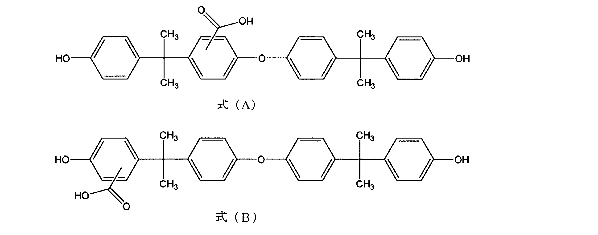
- a compound represented by the following formula (A) (hereinafter referred to as “compound A”) and a following formula (B) in the decomposition product after alkaline hydrolysis of the selected granules are represented.
- the content of each compound (hereinafter referred to as “compound B”) is 5 ppm or less, preferably 3 ppm by weight or less, more preferably 2 ppm by weight or less, and particularly preferably 1 ppm by weight or less.
- the content of Compound A and Compound B in the alkaline hydrolyzate of the selected granules is 5 ppm by weight or less, or the total content of Compound A and Compound B is 5 ppm by weight or less.
- the value of these contents is also preferably 3 ppm by weight or less, more preferably 2 ppm by weight or less, and particularly preferably 1 ppm by weight or less.
- the contents of the compounds A and B in the granules (sorting fluid) can be kept low, and as a result, a substrate with higher transparency can be obtained. Can be manufactured.
- concentration) of the compounds A and B in the decomposition product after carrying out the alkaline hydrolysis of the powder body (selection granule) is as follows.
- the contents (concentrations) of compounds A and B in the decomposition product after alkaline hydrolysis of the granular material (selected granular material) are measured using LC-MS / MS as follows. First, a 0.1 g sample of powder is dissolved in 10 ml of dichloromethane. To this dichloromethane solution, 1.8 ml of 28% sodium methoxide in methanol, 8 ml of methanol and 2.6 ml of water are added and stirred for 1 hour. To this solution, 12 ml of 1N hydrochloric acid aqueous solution is added and stirred for 10 minutes. After acidifying the system, the solution is allowed to stand.
- the organic layer of dichloromethane separated from the aqueous layer is made up to 10 ml, and 2 ml of dichloromethane solution is collected.
- This dichloromethane solution is dried under a nitrogen stream, and the obtained sample is dissolved in 2 ml of an acetonitrile solution of 10 mg / l methoxysalicylic acid as an internal standard solution to obtain an LC-MS / MS measurement sample.
- the content of compounds A and B in the alkaline hydrolyzate of the granular material (selected granular material) is calculated by LC-MS / MS measurement on this measurement sample.
- the contents of the compounds A and B in the alkali hydrolyzate of the polycarbonate resin powder are closely related to the hue of the powder. That is, powders having a low content of compounds A and B are nearly colorless and excellent in hue, whereas powders having a high content of compound A or B are colored yellow or amber. It tends to be inferior in hue.
- a pellet having a good hue is produced by using the selected granule obtained by removing fine powder from the granule as described above, and the compound A in the alkaline hydrolyzate of the selected granule and The B content is suppressed to 5 ppm by weight or less.
- melt molding process injection molding process
- the above-described selected granules are molded.
- the selected granules are injection molded to produce polycarbonate resin injection molded products.
- Components of Melt (Injection) Molded Product In the melt molding step such as the injection molding step, the following components can be added in addition to the polycarbonate resin selected granules.
- antioxidants phosphorus-based, sulfur-based heat stabilizers, benzotriazole-based, triazine-based UV absorbers, carboxylic acid esters, polysiloxane compounds, paraffin wax (polyolefin-based), release agents such as polycaprolactone, Or additives, such as an optical stabilizer, are mentioned.
- antioxidants examples include organic phosphorus compounds such as organic sulfur compounds and phosphites.
- phosphite compound (a), phosphorous acid (b) in which at least one ester in the molecule is esterified with phenol and / or phenol having at least one alkyl group having 1 to 25 carbon atoms And at least one selected from the group of tetrakis (2,4-di-tert-butylphenyl) -4,4′-biphenylene-di-phosphonite (c).
- phosphite compound (a) examples include trioctyl phosphite, tridecyl phosphite, triphenyl phosphite, trisnonylphenyl phosphite, tris (octylphenyl) phosphite, tris (2,4-di-).
- tert-butylphenyl) phosphite tridecyl phosphite, didecyl monophenyl phosphite, dioctyl monophenyl phosphite, diisopropyl monophenyl phosphite, monobutyl diphenyl phosphite, monodecyl diphenyl phosphite, monooctyl diphenyl phosphite, Distearyl pentaerythritol diphosphite, diphenylpentaerythritol diphosphite, bis (2,6-di-tert-butyl-4-methylphenyl) pentaerythritol diphosphite Phyto, 2,2-methylenebis (4,6-di-tert-butylphenyl) octyl phosphite, bis (nonylphenyl) pentaeryth
- Examples of the release agent include at least one compound selected from the group consisting of aliphatic carboxylic acids, esters of aliphatic carboxylic acids and alcohols, aliphatic hydrocarbon compounds having a number average molecular weight of 200 to 15000, and polysiloxane silicone oils. be able to.
- Examples of the aliphatic carboxylic acid include saturated or unsaturated aliphatic monovalent, divalent or trivalent carboxylic acid.
- the aliphatic carboxylic acid includes an alicyclic carboxylic acid.
- preferable aliphatic carboxylic acids are monovalent or divalent carboxylic acids having 6 to 36 carbon atoms, and aliphatic saturated monovalent carboxylic acids having 6 to 36 carbon atoms are more preferable.
- aliphatic carboxylic acid examples include palmitic acid, stearic acid, caproic acid, capric acid, lauric acid, arachidic acid, behenic acid, lignoceric acid, serotic acid, mellicic acid, tetrariacontanoic acid, montanic acid, adipic acid, And azelaic acid.
- the aliphatic carboxylic acid in the ester of an aliphatic carboxylic acid and an alcohol examples of the same one as the aliphatic carboxylic acid can be used.
- examples of the alcohol include saturated or unsaturated monovalent or polyhydric alcohols. These alcohols may have a substituent such as a fluorine atom or an aryl group.
- a monovalent or polyvalent saturated alcohol having 30 or less carbon atoms is preferable, and an aliphatic saturated monohydric alcohol or polyhydric alcohol having 30 or less carbon atoms is more preferable.
- the aliphatic includes alicyclic compounds.
- alcohols include octanol, decanol, dodecanol, stearyl alcohol, behenyl alcohol, ethylene glycol, diethylene glycol, polypropylene glycol, glycerin, pentaerythritol, 2,2-dihydroxyperfluoropropanol, neopentylene glycol, ditrimethylolpropane, dipentaerythritol. Etc.
- said ester compound may contain aliphatic carboxylic acid and / or alcohol as an impurity, and may be a mixture of a some compound.
- esters of aliphatic carboxylic acids and alcohols include beeswax (a mixture based on myricyl palmitate), stearyl stearate, behenyl behenate, stearyl behenate, glycerin monopalmitate, glycerin monostearate Glycerol distearate, glycerol tristearate, pentaerythritol monopalmitate, pentaerythritol monostearate, pentaerythritol distearate, pentaerythritol tristearate, pentaerythritol tetrastearate and the like.
- Examples of the aliphatic hydrocarbon having a number average molecular weight of 200 to 15000 include liquid paraffin, paraffin wax, microwax, polyethylene wax, Fischer-Tropsch wax, and ⁇ -olefin oligomer having 3 to 12 carbon atoms.
- the alicyclic hydrocarbon is also included in the aliphatic hydrocarbon.
- these hydrocarbon compounds may be partially oxidized.
- paraffin wax, polyethylene wax, or a partial oxide of polyethylene wax is preferable, and paraffin wax and polyethylene wax are more preferable.
- the number average molecular weight is preferably 200 to 5,000.
- aliphatic hydrocarbons may be a single substance or a mixture of components and various molecular weights as long as the main component is within the above range.
- examples of the polysiloxane silicone oil include dimethyl silicone oil, phenylmethyl silicone oil, diphenyl silicone oil, and fluorinated alkyl silicone. Two or more of these may be used in combination.
- additives may be added directly to the polycarbonate resin selected granules by directly mixing the total amount required by a tumbler, mixer, etc., forming a master batch consisting of all types of additives, injection molded products You may use for manufacture of melt-molded articles, such as. Further, all necessary amounts of some kinds of additives may be mixed with each other, and a master batch may be formed for other additives.
- the selected granules are dried, and the moisture content in the selected granules is preferably suppressed to 300 ppm by weight or less, more preferably 200 ppm by weight or less.
- the selected granule is melt-molded in an atmosphere in which the oxygen concentration in the system is 10,000 ppm or less, preferably 5000 ppm or less, more preferably 2000 ppm or less by addition of inert gas and / or reduced pressure. ⁇ Please check because it added.
- the fluorescence detection / analysis substrate is a generic term for members that are used in devices (analytical instruments, microscopes) that detect fluorescence as a signal, and require that the material's autofluorescence is small. Especially in the fields of biochemistry, medical diagnosis (clinical testing), drug discovery, microbiological testing, food, environment, healthcare, etc., to operate and analyze biological substances and chemical compounds to be analyzed with high accuracy and efficiency Refers to the device substrate. Specific examples include biochips and reaction chips.
- the shape of the fluorescence detection analysis substrate is not particularly limited, and examples thereof include a substrate shape (slide glass shape, card shape, disk shape, etc.), fiber shape, spherical shape, tube shape, film shape, (micro) well shape, and the like. . Further, it may be a member directly hit by the detection light or a member around it.
- a biochip is a substrate (support) on which a biological substance or compound to be analyzed is immobilized, and this immobilized product (probe) or another compound (target) is brought into contact with each other, resulting in a specific mutual relationship.
- immobilized product probe
- target another compound
- reaction is not limited to the case where the chemical structure is changed due to a chemical reaction due to an ionic bond or a covalent bond, but also other bonds such as hydrogen bond, coordination bond, van der Waals force, chemical adsorption, and physical adsorption. It also means an action that can create a situation where it is combined with other substances depending on the mode.
- the biological substance include DNA fragments, synthetic nucleotides, proteins, enzymes, antigens, antibodies, epitopes, sugar chains, glycoproteins, glycolipids, cells, and the like.
- the fluorescence detection / analysis substrate of the present invention is used for fluorescence detection / analysis substrate (DNA microarray) used for DNA extraction / purification / amplification / recovery / analysis, etc., and protein purification / crystallization / expression / analysis / condition search.
- Biochips such as protein chips (protein arrays), antibody chips, sugar chains used to analyze sugar chain supplementation / sugar chain-protein interactions, and cell chips used for cell separation / analysis Including.
- Fluorescence detection / analysis substrate in the present invention may be subjected to surface modification, surface treatment, etc. on the substrate surface within a range not impairing the effects of the present invention.
- Various methods can be used as the surface modification method. Specifically, for example, by introducing an aldehyde group, the physiologically active substance is covalently bonded on the substrate and is more firmly fixed. Is preferably introduced.
- aldehyde group introduction means a method of reacting a polyfunctional aldehyde after amino group introduction is preferable.
- amino group introduction means include treatment with an amino group-containing silane coupling agent, plasma treatment under a nitrogen atmosphere, and coating of an amino group-containing polymer substance. From the viewpoint of simplicity of treatment and uniformity. The treatment with an amino group-containing silane coupling agent is preferred.
- a preferable example of the polyfunctional aldehyde is glutaraldehyde.
- Various methods are used as the surface treatment method, and examples thereof include a method of treating with a cationic polymer, poly-L-lysine, polyethylene glycol (derivative), phosphatidylcholine group-containing polymer, and the like.
- a granular material of a common polycarbonate resin (H-4000F: aromatic polycarbonate resin manufactured by Mitsubishi Engineering Plastics Co., Ltd.) (particle size distribution 50-1200 ⁇ m, average particle size 800 ⁇ m, solution YI value 1. 33)
- H-4000F aromatic polycarbonate resin manufactured by Mitsubishi Engineering Plastics Co., Ltd.
- particle size distribution 50-1200 ⁇ m, average particle size 800 ⁇ m, solution YI value 1. 33 Each sample of the selected granule in Table 1 below from which fine powder was removed was injection molded, and the fluorescence spectrum and the total concentration of compounds A and B were measured for the molded product.
- the selected granule of sample 1 was obtained by removing fine powder having a particle size of less than 500 ⁇ m from the above resin granule using a sieve having an opening of 500 ⁇ m.
- the selected granule of sample 2 removes fine powder from the resin granule using a classification device (Freund Turbo Co., Ltd .: turbo screener) that can automatically sort the granule. Was obtained.
- the selected granule of Sample 2 was selected as follows. First, a blade in a cylindrical mesh made of synthetic fiber having a mesh size of 500 mesh provided in a classifier was rotated at high speed. In this state, air was sucked by a suction device (air blowing means), whereby powder particles were supplied from the end opening of the cylindrical mesh to the inside of the cylinder along with the air, and fine vibration was generated in the mesh. As a result, most of the powders with small particle diameters dropped relatively quickly through the side surface of the cylindrical mesh, whereas the selected granules that do not pass through the mesh and the slightly small powders It moved to the end opposite to the opening to which the granules were supplied and dropped from the opening.
- a suction device air blowing means
- the selected granule of sample 2 contained a small amount of powder having a small particle size. That is, sample 1 does not contain fine powder having a particle size equal to or smaller than the size of each sieve used, whereas sample 2 has a particle size of less than 500 ⁇ m. About 3 to 5% by weight based on the total weight of the granules was contained. As described above, by using the classifying apparatus, although a small amount of particles having a small particle diameter is included in the selected particles, a large amount of particles can be quickly selected by using centrifugal force.
- the comparative sample 1 is an unsorted resin particle itself.
- an injection molded product was manufactured using the selected granule of Sample 1 described above.
- an injection molding machine 100 shown in FIG. 3 was used.
- the injection molding machine 100 is attached to a molding cylinder 10 having a resin outlet 11 at the tip, a screw 15 built in the molding cylinder 10, and a molding cylinder 10, and raw material selection granules in the molding cylinder 10. 1, a hopper 20 for supplying 1, a screw driving device 18 attached to the rear end portion 16 of the screw 15, and the like.
- the screw 15 disposed in the molding cylinder 10 is an in-line screw that plasticizes and melts the selected granule 1 and also functions as a plunger.
- a heater (not shown) is attached to the outer periphery of the molding cylinder 10, and the selected granule 1 existing in the gap 17 between the molding cylinder 10 and the screw 15 can be plasticized and melted.
- the selected granule 1 and the additive (not shown) described later were carried into the hopper 20 from the resin storage part via the pipe (not shown) and the carry-in part 21.
- the composition of the selected granule 1 and the additive used is as follows.
- Selected Granule 1 (Sample 2 above, Polycarbonate resin Iupilon H-4000F (Mitsubishi Engineering Plastics): 99.92 parts by weight ADK STAB PEP36 (bis (2,6-di-tert-butyl-4-ethylphenyl) penta Erythritol diphosphite Adeka): 0.05 parts by weight Riquemar S100A (glycerin monostearate, manufactured by Riken Vitamin): 0.03 parts by weight
- a blower (not shown) is disposed downstream of the exhaust part 22 provided in the hopper 20, and the inside of the hopper 20 is brought to a negative pressure by the operation of the blower, from the raw material polycarbonate resin storage part through the piping and the carry-in part 21.
- the flake-shaped selected granules 1 were carried into the hopper 20 by airflow.
- the carrying-in system of the selection granule 1 from the resin storage part to the hopper 20 can be an arbitrary system.
- the selected granules 1 carried into the molding cylinder 10 from the hopper 20 were heated, plasticized, melted and conveyed by the molding cylinder 10 and the screw 15.
- the preset melting temperature of the barrel (molding cylinder) 10 was 240 ° C.
- the screw 15 is rotated forward by the operation of the screw drive device 18 and is pushed forward, and pressure is applied to the selected granule 1 ′ containing the melted additive in the molding cylinder 10. Injection was performed from the lead-out portion 11 toward the molten resin injection portion 54 (see FIG. 4) of the mold assembly 50.
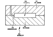
- the melt-selected granule 1 ′ flowed into the cavity 53 provided between the first mold part 51 and the second mold part 52 via the molten resin injection part 54.
- the melt-selected granule 1 ′ was filled in the gap 17 between the molding cylinder 10 and the screw 15 from the part of the molding cylinder 10 to which the hopper 20 is attached to the resin outlet 11. Only a part of them is shown in FIG.
- An airtight member 13 for attaching the rear end portion 12 to the airtight structure is attached to the rear end portion 12 of the molding cylinder 10 on the screw driving device 18 side, and between the airtight member 13 and the screw 15.
- a sealing member 14 for airtight is attached to the airtight member 13.
- the injection molding machine 100 further includes an inert gas source 30 and a pipe 32 for introducing the inert gas from the inert gas source 30 into the molding cylinder 10.
- the pipe 32 is attached to the portion of the molding cylinder 10 on the screw drive device side of the part of the molding cylinder 10 to which the hopper 20 is attached, more specifically, to the airtight member 13.
- the pipe 32 may be attached to the rear end portion 12 of the molding cylinder 10 on the screw drive device side.
- a pressure control valve 33 and a pressure sensor 34 are disposed in the middle of the pipe 32.
- a second pressure sensor 35 is attached to the hopper 20 in order to detect the pressure in the hopper 20.
- pressure control valve 33 and the pressure sensors 34 and 35 those having a well-known system, structure and configuration can be used.
- the outputs of the pressure sensors 34 and 35 are sent to the pressure control device 31, and the operations of the pressure control valve 33 and the inert gas source 30 are controlled by the output of the pressure control device 31.
- the inert gas inlet 38 is a gap through which the inert gas passes but the raw material polycarbonate resin does not enter.
- the position and the shape of the inert gas inlet 38 are not particularly limited as long as the inert gas can pass therethrough and the raw material polycarbonate resin can be prevented from flowing out. It is not linear but more preferably circular.
- the inert gas was allowed to flow out of the system from the inert gas source 30 via the pipe 32, the inert gas inlet 38, the molding cylinder 10, and the exhaust part 22 of the hopper 20.
- the selected particles 1 are filled in the hopper 20, and the gap 17 between the molding cylinder 10 and the screw 15 from the portion of the molding cylinder 10 to which the hopper 20 is attached to the resin outlet portion 11. Inside, the selected granule 1 was plasticized.
- the pressure of the portion of the molding cylinder through which the inert gas flows (specifically, the rear end portion 12) is, for example, about 2 ⁇ 10 3 Pa (0.02 kgf / cm 2 ) higher than the atmospheric pressure.
- the pressure or pressure change of the inert gas at the rear end 12 can be detected by the pressure sensor 34, and the pressure control valve 33 is controlled via the pressure control device 31 based on the detection result of the pressure.
- the flow rate of the inert gas can be controlled. Further, when the selected granule 1 is brought into the hopper 20 by airflow, the inside of the hopper 20 becomes a negative pressure.
- the gas generated from the selected granular material 1 ′ plasticized and melted in the gap 17 between the molding cylinder 10 and the screw 15 passes through the hopper 20 together with the inert gas flowing in the molding cylinder 10. It was discharged out of the system from the exhaust part 22.
- the oxygen gas concentration in the hopper 20 into which the selected granule 1 as the raw material was charged and the nitrogen gas supplied from the inert gas source 30 was 200 ppm. Further, the oxygen gas concentration may be reduced by using an injection molding machine 110 provided with an exhaust port (vent portion) 19 in the molding cylinder 10 shown in FIG. In the injection molding machine 110, it is possible to easily depressurize the system using a vacuum pump (not shown) through the exhaust port (vent part) 19 or inject nitrogen while depressurizing the system. is there.
- injection molding was performed under the following conditions.
- Injection molding machine Sodick Plustech injection molding machine TR100EH2 Molded product dimensions: Length 100 mm x Width 100 mm Thickness 3 mm Molding temperature: 280 ° C Mold temperature: 100 ° C Molding cycle: 40 seconds
- the injection resin was injected from the resin outlet 11 by this injection molding (see FIG. 3), and the polycarbonate resin filled in the cavity 53 was cooled to produce an injection molded product having a shape corresponding to the cavity 53 (see FIG. 4).
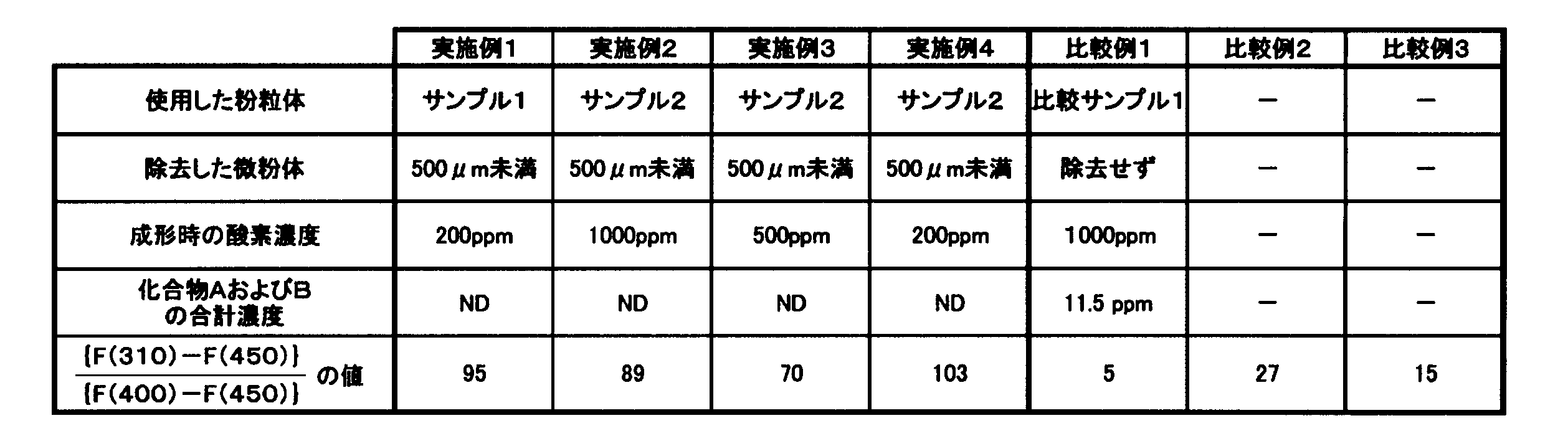
- injection molded products were produced using the selected granules of Samples 1 and 2 and Comparative Sample 1, and Examples 1 to 4 and Comparative Example 1 were obtained as shown in Table 2 below.
- the injection molded products of Examples 2 to 4 and Comparative Example 1 were manufactured by the same manufacturing method as in Example 1 above, except that the oxygen gas concentration during the molding process was different.
- the fluorescence intensity of the flat plate test pieces obtained in Examples 1 to 4 and Comparative Example 1 was measured. As shown in FIG. 1, the fluorescence intensity was evaluated by comparing the 3 mm-thick flat plate test pieces obtained in Examples 1 to 4 and Comparative Example 1 with the incident angle of the excitation light beam and the emission angle on the fluorescence measurement side. Both were installed at 45 °, and a fluorescence emission spectrum was measured in a three-dimensional measurement mode and a fluorescence data mode using a Hitachi High-Tech F-4500 type spectrofluorometer.
- the measurement conditions were: excitation side sampling interval 10 nm, excitation side slit interval 1 nm, fluorescence side sampling interval 5 nm, fluorescence side slit interval 2.5 nm, scan speed 240 nm / min, PMT voltage 950 V, response 0. It was 004 seconds, spectrum correction On, and shutter control On.
- the wavelength of the excitation light was 290 nm.
- the fluorescence emission spectrum was measured at room temperature.
- the fluorescence emitted by the sample is detected. Therefore, it is preferable that the autofluorescence intensity of the substrate is small. Since the wavelength of fluorescence emitted from the analysis sample is generally in the visible light region, it is effective that the autofluorescence of the fluorescence detection / analysis substrate is remarkably small in this region. Since polycarbonate is used as the material for the fluorescence detection / analysis substrate made of polycarbonate, fluorescence emission derived from the structure of the polycarbonate can be seen around 310 nm.
- the cause of the fluorescence emitted in the visible light region is found to be various branched structures caused by the heat applied in the process of molding, etc., and the fluorescence intensity near 310 nm is reduced, Instead, it was found that the fluorescence intensity at a wavelength in the visible light region near 330 to 410 nm on the longer wavelength side from 310 nm significantly increases.
- the fluorescence emission of the sample analyzed by the fluorescence detection / analysis substrate is often in the visible light region, it is preferable that the emission of the analysis substrate does not exist in the visible light region.
- the light emission in the visible light region of the polycarbonate analysis substrate is small, that is, the fluorescence intensity at 310 nm, which is the original fluorescence emission of polycarbonate, is longer in the visible light region. In other words, it is stronger.
- the preferred fluorescence spectrum as the fluorescence detection and analysis substrate is exemplified by the solid line, and the substrate having the fluorescence spectrum exemplified by the broken line represents the fluorescence intensity in the visible light region. Can not be used because of the large.
- the present inventors have found that the molded article satisfies the following formula (1) in order to be effective as a polycarbonate fluorescence detection / analysis substrate.
- ⁇ 40 Formula (1) (In Formula (1), F (310), F (400), and F (450) are relative values of fluorescence emission intensities at wavelengths of 310 nm, 400 nm, and 450 nm, respectively).
- the value on the left side of the formula (1) is preferably 45 or more, more preferably 55 or more, and more preferably 65 or more.
- the aromatic polycarbonate having a structural viscosity index N of 1.2 or less described in Patent Document 4 contains 0.1% and 0.3% of a benzotriazole-based UV absorber, respectively. It is the value of the formula (1) of the polycarbonate resin composition.
- the polycarbonate resin compositions shown in Comparative Example 2 and Comparative Example 3 have a small value of the formula (1). Therefore, the resin compositions of Comparative Example 2 and Comparative Example 3 have relatively high fluorescence intensity in the visible light region compared to the fluorescence intensity of 310 nm derived from the aromatic polycarbonate, and satisfy the performance as a fluorescence detection / analysis substrate. I did not.
- Examples 1 to 4 were subjected to alkaline hydrolysis, and impurities contained in Examples 1 to 4 were identified and quantified by LC-MS / MS measurement on the decomposed product.
- compound A represented by formula (A) was not detected.
- Comparative Example 1 since it was contained at a concentration of 11.5 ppm by weight, it was confirmed that the concentration of Compound A was related to the value of fluorescence intensity.
- the injection molding materials of Examples 1 to 4 and Comparative Example 1 are used.
- the solution YI values of powder sample 1, sample 2, and comparative sample 1 were measured.
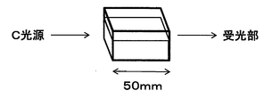
- FIG. 2 shows a schematic diagram of measurement of the solution YI value.
- the solution YI value is measured by dissolving 12 g of a granular sample in 80 ml of dichloromethane (special grade), placing it in a transparent glass cell with an optical path length of 50 mm, and using an SD6000 spectrocolorimeter manufactured by Nippon Denshoku Industries Co., Ltd. It was measured.
- extremely low autofluorescence is obtained by removing fine powder from the polycarbonate resin powder obtained by the interfacial polymerization method, and selecting the granules to produce an injection molded product or the like.
- a fluorescence detection and analysis substrate made of polycarbonate resin having the above can be obtained.
Landscapes
- Health & Medical Sciences (AREA)
- Chemical & Material Sciences (AREA)
- Life Sciences & Earth Sciences (AREA)
- Engineering & Computer Science (AREA)
- Medicinal Chemistry (AREA)
- Molecular Biology (AREA)
- Biomedical Technology (AREA)
- Urology & Nephrology (AREA)
- Hematology (AREA)
- Immunology (AREA)
- Chemical Kinetics & Catalysis (AREA)
- Polymers & Plastics (AREA)
- Organic Chemistry (AREA)
- Food Science & Technology (AREA)
- General Health & Medical Sciences (AREA)
- Cell Biology (AREA)
- Biotechnology (AREA)
- Physics & Mathematics (AREA)
- Analytical Chemistry (AREA)
- Biochemistry (AREA)
- Microbiology (AREA)
- General Physics & Mathematics (AREA)
- Pathology (AREA)
- Compositions Of Macromolecular Compounds (AREA)
- Investigating, Analyzing Materials By Fluorescence Or Luminescence (AREA)
- Polyesters Or Polycarbonates (AREA)
- Manufacturing & Machinery (AREA)
- Mechanical Engineering (AREA)
Abstract
Description
本発明では、界面重合法により得られたポリカーボネート樹脂の粉粒体から微粉を取り除くことにより、詳細を後述する化合物の含有量を低く抑えることができ、その結果、ポリカーボネート樹脂選別粒体中の分岐構造の量を低減できることを見出した。この選別粒体を例えば射出成形することによって得られた透明成形体は、蛍光波長310nm付近のポリカーボネート樹脂に特徴的な自家蛍光が強いものの、その自家蛍光発光の波長範囲は極めて狭く、400nm~700nmの可視光域における自家蛍光が著しく低いことを見出した。
(I)界面重合法にて合成されたポリカーボネート樹脂を含有し、波長290nmの光で励起した場合の蛍光発光において、波長310nm、400nm、450nmの蛍光発光強度をそれぞれF(310)、F(400)、F(450)とした時、下記式(1)を満たすポリカーボネート樹脂組成物。
|{F(310)-F(450)}/{F(400)-F(450)}|≧40
式(1)
(II)上記(I)に記載の前記ポリカーボネート樹脂組成物を含むポリカーボネート樹脂製蛍光検出分析基板。
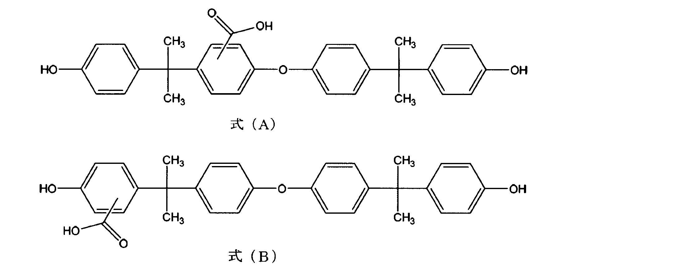
(III)前記蛍光検出分析基板をアルカリ加水分解した後の分解物中の下記式(A)で表される化合物および下記式(B)の合計含有量が5重量ppm以下である、上記(II)に記載のポリカーボネート樹脂製蛍光検出分析基板。
(V)界面重合法により得られたポリカーボネート樹脂が粉粒体であり、前記粉粒体の溶融成形工程により製造されたことを特徴とする、上記(II)から(IV)のいずれかに記載のポリカーボネート樹脂製蛍光検出分析基板。
(VI)前記粉粒体から微粉を取り除く粒体選別工程により得られた、500μm以上の粒径を有する粒体の含有量が90重量%以上である選別粒体を用いて製造された、上記(V)に記載のポリカーボネート樹脂製蛍光検出分析基板。
(VII)前記粒体選別工程において、風力を利用して前記粉粒体から得られた前記選別粒体を用いて製造された、上記(VI)に記載のポリカーボネート樹脂製蛍光検出分析基板。
(VIII)送風手段を利用して浮遊させた前記微粉を除去して得られた前記選別粒体を用いて製造された、上記(VI)または(VII)に記載のポリカーボネート樹脂製蛍光検出分析基板。
(IX)前記粒体選別工程において、ふるいを用いて前記粉粒体から得られた前記選別粒体を用いて製造された、上記(VI)に記載のポリカーボネート樹脂製蛍光検出分析基板。
(X)前記粒体選別工程において、さらにふるいを用いて前記粉粒体から得られた前記選別粒体を用いて製造された、上記(VII)または(VIII)に記載のポリカーボネート樹脂製蛍光検出分析基板。
(XI)前記ふるいを振動させている状態で前記微粉を除去して得られた前記選別粒体を用いて製造された、上記(IX)または(X)に記載のポリカーボネート樹脂製蛍光検出分析基板。
(XII)溶液YI値が1.30以下である前記選別粒体を用いて製造された、上記(IX)から(XI)のいずれかに記載のポリカーボネート樹脂製蛍光検出分析基板。
(XIII)溶融成形前に乾燥させて含水率を200ppm以下とした前記ポリカーボネート粉粒体により製造された、上記(V)から(XII)のいずれかに記載のポリカーボネート樹脂製蛍光検出分析基板。
(XIV)前記溶融成形工程において、不活性ガスの添加および/または減圧により酸素濃度を10000ppm以下とした雰囲気下で前記選別粒体を溶融成形して製造された、上記(V)から(XIII)のいずれかに記載のポリカーボネート樹脂製蛍光検出分析基板。
(XV)前記溶融成形工程が射出成形工程である、上記(V)から(XIV)のいずれかに記載のポリカーボネート樹脂製蛍光検出分析基板。
本発明におけるポリカーボネート樹脂の粉粒体は、界面重合法により生成される。
具体的には、ポリカーボネート樹脂は、芳香族ジヒドロキシ化合物又はこれと少量のポリヒドロキシ化合物と、一般にホスゲンとして知られている塩化カルボニル、又は、ジメチルカーボネートやジフェニルカーボネートに代表される炭酸ジエステル、一酸化炭素や二酸化炭素と云ったカルボニル系化合物とを、反応させることによって得られる。本発明におけるポリカーボネート樹脂は、直鎖状、又は本発明の効果が失われない範囲で分岐していても良い熱可塑性芳香族ポリカーボネートの重合体、又は共重合体である。
ビス-(4-ヒドロキシフェニル)メタン、ビス-(4-ヒドロキシ-5-ニトロフェニル)メタン、1,1-ビス(4-ヒドロキシフェニル)エタン、3,3-ビス(4-ヒドロキシフェニル)ペンタン、1,1-ビス(4-ヒドロキシフェニル)シクロヘキサン、ビス(4-ヒドロキシフェニル)スルホン、2,4’-ジヒドロキシジフェニルスルホン、ビス(4-ヒドロキシフェニル)スルフィド、4,4’-ジヒドロキシジフェニルエーテル、4,4’-ジヒドロキシ-3,3’-ジクロロジフェニルエーテル、4,4’-ジヒドロキシ-2,5-ジエトキシジフェニルエーテル、1-フェニル-1,1-ビス(4-ヒドロキシフェニル)エタン、1,1-ビス(4-ヒドロキシ-3-メチルフェニル)シクロヘキサン、1-フェニル-1,1-ビス(4-ヒドロキシ-3-メチルフェニル)エタン等を挙げることができるが、好ましくは、ビス(4-ヒドロキシフェニル)アルカン類であり、特に好ましくは、2,2-ビス(4-ヒドロキシフェニル)プロパン[ビスフェノールAと呼ばれる]である。これらの芳香族ジヒドロキシ化合物は、単独で、又は、2種以上を混合して使用することができる。
本発明では、粒体選別工程において、ポリカーボネート樹脂の粉粒体から、微粉、すなわち、粉粒体に含まれる他の粒体よりも粒径の小さい微粉を除去して選別粒体を得る。選別粒体は、所定の基準粒径以上の粒径を有する粒体を所定の基準含有量以上含有しており、例えば、200μm以上の粒径を有する粒体を90重量%以上含有する。選別粒体の基準粒径と基準含有量は、使用する粉粒体の粒径分布、および色相等に応じて適宜選択される。例えば、基準粒径は、100μm、200μm、500μm、1000μm等であり、基準含有量は、80重量%、90重量%、95重量%、97重量%等である。
所定の大きさの目開きを有するふるいにより粉粒体をふるい、微粉を除去することができる。このようなふるいとして、例えば、金属網または樹脂網のJIS標準ふるい(JIS Z 8801-1)などが使用できる。ただし、JIS規格に準じないふるいを使用しても良い。また、ふるい(網)を備えた分級装置を利用しても良い。この場合、ふるいを振動させること等により、粉粒体から効率的に微粉を除去することができる。
送風機能を有する風力選別機を用いて、送風により粉粒体を浮遊させた状態で、微粉を除去しても良い。風力選別機では、例えば、筒の下方に設置した送風機(送風手段)により筒内に上方に向かう風を発生させつつ、粉粒体を浮遊させる。このとき、微粉は風力により飛ばされて筒を通過し、筒に連結された拡散室に達するのに対し、微粉よりも粒径が大きく重い粉体は、一時的に浮遊したとしても重力により筒内を落下する。この結果、微粉と、より粒径の大きい選別粒体とを分離し、選別粒体を得ることができる。
また、風力選別機の構造はこれに限られない。例えば、機内の上方に設置した排風機により系内を減圧させ、微粉を減圧系内に移動させつつ、選別粒体を落下させても良い。また、拡散室を有する送風路に粉粒体を供給し、微粉を浮遊させて拡散室に送るとともに、選別粒体を、粉粒体の供給口付近で落下させても良い。なお、部分的に自然風を活用しても良い。
本発明では、選別粒体をアルカリ加水分解した後の分解物中の下記式(A)で表される化合物(以下、「化合物A」と呼ぶ)および下記式(B)で表される化合物(以下、「化合物B」と呼ぶ)の含有量が、それぞれ5ppm以下、好ましくは3重量ppm以下、より好ましくは2重量ppm以下、特に好ましくは1重量ppm以下である。また、選別粒体のアルカリ加水分解物中の化合物Aおよび化合物Bの含有量が、いずれも5重量ppm以下であること、または、化合物Aおよび化合物Bの合計含有量が5重量ppm以下であることがより好ましい。さらにこれらの含有量の値も、好ましくは3重量ppm以下、より好ましくは2重量ppm以下、特に好ましくは1重量ppm以下である。本発明では、ポリカーボネート樹脂の粉粒体から微粉を取り除くことにより、粉粒体(選別流体)における化合物AおよびBの含有量を低く抑えることができ、その結果、より透明性に優れた基板を製造することができる。なお、粉粒体(選別粒体)をアルカリ加水分解した後の分解物における化合物AおよびBの含有量(濃度)の測定方法は、以下の通りである。

本発明では、例えば射出成形工程などの溶融成形工程において、上記の選別粒体を成形する。射出成形工程においては、選別粒体を射出成形し、ポリカーボネート樹脂の射出成形品を製造する。
射出成形工程などの溶融成形工程においては、ポリカーボネート樹脂の選別粒体の他にも、以下の成分を加えることができる。例えば、酸化防止剤、リン系、硫黄系の熱安定剤、ベンゾトリアゾール系、トリアジン系の紫外線吸収剤、カルボン酸エステル、ポリシロキサン化合物、パラフィンワックス(ポリオレフィン系)、ポリカプロラクトン等の離型剤、または光安定剤等の添加剤などが挙げられる。
酸、リグノセリン酸、セロチン酸、メリシン酸、テトラリアコンタン酸、モンタン酸、アジピン酸、アゼライン酸等を挙げることができる。脂肪族カルボン酸とアルコールとのエステルにおける脂肪族カルボン酸として、前記脂肪族カルボン酸と同じものが使用できる。一方、アルコールとして、飽和又は不飽和の1価又は多価アルコールを挙げることができる。これらのアルコールは、フッ素原子、アリール基等の置換基を有していてもよい。これらの中では、炭素数30以下の1価又は多価の飽和アルコールが好ましく、炭素数30以下の脂肪族飽和1価アルコール又は多価アルコールが更に好ましい。ここで、脂肪族には脂環式化合物も包含される。アルコールの具体例として、オクタノール、デカノール、ドデカノール、ステアリルアルコール、ベヘニルアルコール、エチレングリコール、ジエチレングリコール、ポリプロピレングリコール、グリセリン、ペンタエリスリトール、2,2-ジヒドロキシペルフルオロプロパノール、ネオペンチレングリコール、ジトリメチロールプロパン、ジペンタエリスリトール等を挙げることができる。尚、上記のエステル化合物は、不純物として脂肪族カルボン酸及び/又はアルコールを含有していてもよく、複数の化合物の混合物であってもよい。脂肪族カルボン酸とアルコールとのエステルの具体例として、蜜ロウ(ミリシルパルミテートを主成分とする混合物)、ステアリン酸ステアリル、ベヘン酸ベヘニル、ベヘン酸ステアリル、グリセリンモノパルミテート、グリセリンモノステアレート、グリセリンジステアレート、グリセリントリステアレート、ペンタエリスリトールモノパルミテート、ペンタエリスリトールモノステアレート、ペンタエリスリトールジステアレート、ペンタエリスリトールトリステアレート、ペンタエリスリトールテトラステアレート等を挙げることができる。数平均分子量200~15000の脂肪族炭化水素として、流動パラフィン、パラフィンワックス、マイクロワックス、ポリエチレンワックス、フィッシャートロプシュワックス、炭素数3~12のα-オレフィンオリゴマー等を挙げることができる。ここで、脂肪族炭化水素には脂環式炭化水素も含まれる。また、これらの炭化水素化合物は部分酸化されていてもよい。これらの中では、パラフィンワックス、ポリエチレンワックス又はポリエチレンワックスの部分酸化物が好ましく、パラフィンワックス、ポリエチレンワックスが更に好ましい。数平均分子量は、好ましくは200~5000である。これらの脂肪族炭化水素は単一物質であっても、構成成分や分子量が様々なものの混合物であってもよく、主成分が上記の範囲内であればよい。ポリシロキサン系シリコーンオイルとして、例えば、ジメチルシリコーンオイル、フェニルメチルシリコーンオイル、ジフェニルシリコーンオイル、フッ素化アルキルシリコーン等を挙げることができる。これらの2種類以上を併用してもよい。
詳細を後述する基板の溶融成形方法としては、特に制限は無く、従来公知の任意の樹脂成形方法を用いればよい。具体的には、例えば、射出成形、射出圧縮成形、圧縮成形、押出成形、ホットエンボス(ナノインプリント)成形など一般的な成形方法を採用することができる。特に、生産性、形状の自由度の観点から射出成形、射出圧縮成形が好ましい。また、射出成形時にシリンダー内に超臨界流体を樹脂と共に導入することにより、樹脂の流動性を上げ、微細な形状(溝や穴)の転写性を上げることもできる。
なお、溶融成形工程においては、不活性ガスの添加および/または減圧により、系内の酸素濃度を10000ppm以下、好ましくは5000ppm以下、より好ましくは2000ppm以下とした雰囲気下で選別粒体を溶融成形する⇒追記しましたのでご確認ください。
次に、本発明における蛍光検出分析基板について説明する。蛍光検出分析基板とは、蛍光をシグナルとして検出するデバイス(分析機器、顕微鏡)に使用され、材料の自家蛍光が小さいことが要求されることを特徴とする部材の総称である。特に生化学、医療診断(臨床検査)、創薬、微生物検査、食品、環境、ヘルスケアなどの分野において、分析対象となる生体物質や化学化合物を高精度かつ効率的に操作、分析する為のデバイス基板を指す。具体的には例えば、バイオチップ、反応チップ等が挙げられる。

選別粒体1(上述のサンプル2・ポリカーボネート樹脂ユーピロンH-4000F(三菱エンジニアリングプラスチックス製):99.92重量部
アデカスタブPEP36(ビス(2,6-ジ-tert-ブチル-4-エチルフェニル)ペンタエリスリトールジホスファイト・アデカ製):0.05重量部
リケマールS100A(グリセリンモノステアレート・理研ビタミン製):0.03重量部
尚、成形用シリンダー10それ自体が気密性を有している場合には、気密用部材やシール部材は不要である。図3に、不活性ガスの流れを矢印で示した。
射出成形機 :ソディックプラステック製射出成形機TR100EH2
成形品寸法 :縦100mm×横100mm 厚み3mm
成形温度 :280℃
金型温度 :100℃
成形サイクル :40秒
蛍光強度の評価は実施例1~4、及び比較例1において得られた3mm厚の平板試験片を、図1に示すように、励起光の光線の入射角、および蛍光測定側の出射角がどちらも45°となるように設置し、日立ハイテク社製F-4500形分光蛍光光度計を用い、3次元測定モード、蛍光データモードにて蛍光発光スペクトルを測定した。
測定条件は、励起側サンプリング間隔は10nm、励起側スリット間隔は1nm、蛍光側サンプリング間隔は5nm、蛍光側スリット間隔は2.5nm、スキャンスピードは240nm/min、PMT電圧は950V、レスポンスは0.004秒、スペクトル補正On、シャッタ制御Onであった。また、励起光の波長は290nmであった。
蛍光発光スペクトルの測定は室温で行った。
分析試料が発する蛍光の波長は可視光領域であることが一般的であるため、蛍光検出分析基板の自家蛍光がこの領域で著しく小さいことが有効である。ポリカーボネート製蛍光検出分析基板では素材にポリカーボネートを使用しているため、ポリカーボネートの構造に由来する蛍光発光がおよそ310nm付近に見られる。本願発明者らの検討によると可視光領域で発光する蛍光の原因は成形加工などの過程において与える熱によって生じた種々の分岐構造であることを見出し、前述の310nm付近の蛍光強度が減少し、代わりに310nmより長波長側の330~410nm付近の可視光領域にかかる波長の蛍光強度が著しく増加することが判明した。
|{F(310)-F(450)}/{F(400)-F(450)}|≧40
式(1)(式(1)中、F(310)、F(400)、F(450)は、それぞれ、波長310nm、400nm、450nmの蛍光発光強度の相対値である。)

Claims (15)
- 界面重合法にて合成されたポリカーボネート樹脂を含有し、波長290nmの光で励起した場合の蛍光発光において、波長310nm、400nm、450nmの蛍光発光強度をそれぞれF(310)、F(400)、F(450)とした時、下記式(1)を満たすポリカーボネート樹脂組成物。
|{F(310)-F(450)}/{F(400)-F(450)}|≧40
式(1) - 請求項1に記載の前記ポリカーボネート樹脂組成物を含むポリカーボネート樹脂製蛍光検出分析基板。
- 前記蛍光検出分析基板をアルカリ加水分解した後の分解物中の下記式(A)で表される化合物および下記式(B)の合計含有量が5重量ppm以下である、請求項2に記載のポリカーボネート樹脂製蛍光検出分析基板。

- 前記蛍光検出分析基板をアルカリ加水分解した後の分解物中の前記式(A)および前記式(B)で表される化合物の合計含有量が3重量ppm以下である、請求項3に記載のポリカーボネート樹脂製蛍光検出分析基板。
- 界面重合法により得られたポリカーボネート樹脂が粉粒体であり、前記粉粒体の溶融成形工程により製造されたことを特徴とする、請求項2から4のいずれかに記載のポリカーボネート樹脂製蛍光検出分析基板。
- 前記粉粒体から微粉を取り除く粒体選別工程により得られた、500μm以上の粒径を有する粒体の含有量が90重量%以上である選別粒体を用いて製造された、請求項5に記載のポリカーボネート樹脂製蛍光検出分析基板。
- 前記粒体選別工程において、風力を利用して前記粉粒体から得られた前記選別粒体を用いて製造された、請求項6に記載のポリカーボネート樹脂製蛍光検出分析基板。
- 送風手段を利用して浮遊させた前記微粉を除去して得られた前記選別粒体を用いて製造された、請求項6または7に記載のポリカーボネート樹脂製蛍光検出分析基板。
- 前記粒体選別工程において、ふるいを用いて前記粉粒体から得られた前記選別粒体を用いて製造された、請求項6に記載のポリカーボネート樹脂製蛍光検出分析基板。
- 前記粒体選別工程において、さらにふるいを用いて前記粉粒体から得られた前記選別粒体を用いて製造された、請求項7または8に記載のポリカーボネート樹脂製蛍光検出分析基板。
- 前記ふるいを振動させている状態で前記微粉を除去して得られた前記選別粒体を用いて製造された、請求項9または10に記載のポリカーボネート樹脂製蛍光検出分析基板。
- 溶液YI値が1.30以下である前記選別粒体を用いて製造された、請求項6から11のいずれかに記載のポリカーボネート樹脂製蛍光検出分析基板。
- 溶融成形前に乾燥させて含水率を200ppm以下とした前記ポリカーボネート粉粒体により製造された、請求項5から12のいずれかに記載のポリカーボネート樹脂製蛍光検出分析基板。
- 前記溶融成形工程において、不活性ガスの添加および/または減圧により酸素濃度を10000ppm以下とした雰囲気下で前記選別粒体を溶融成形して製造された、請求項5から13のいずれかに記載のポリカーボネート樹脂製蛍光検出分析基板。
- 前記溶融成形工程が射出成形工程である、請求項5から14のいずれかに記載のポリカーボネート樹脂製蛍光検出分析基板。
Priority Applications (5)
| Application Number | Priority Date | Filing Date | Title |
|---|---|---|---|
| JP2015525137A JP6468187B2 (ja) | 2013-06-30 | 2014-06-19 | ポリカーボネート樹脂組成物およびポリカーボネート樹脂組成物を用いた蛍光検出分析基板 |
| US14/901,210 US9670315B2 (en) | 2013-06-30 | 2014-06-19 | Polycarbonate resin composition, and fluorescence detection/analysis substrate produced using polycarbonate resin composition |
| CN201480038023.XA CN105431487A (zh) | 2013-06-30 | 2014-06-19 | 聚碳酸酯树脂组合物和使用聚碳酸酯树脂组合物得到的荧光检测分析基板 |
| SG11201510629XA SG11201510629XA (en) | 2013-06-30 | 2014-06-19 | Polycarbonate resin composition, and fluorescence detection/analysis substrate produced using polycarbonate resin composition |
| AU2014285371A AU2014285371A1 (en) | 2013-06-30 | 2014-06-19 | Polycarbonate resin composition, and fluorescence detection/analysis substrate produced using polycarbonate resin composition |
Applications Claiming Priority (2)
| Application Number | Priority Date | Filing Date | Title |
|---|---|---|---|
| JP2013-137664 | 2013-06-30 | ||
| JP2013137664 | 2013-06-30 |
Publications (1)
| Publication Number | Publication Date |
|---|---|
| WO2015001971A1 true WO2015001971A1 (ja) | 2015-01-08 |
Family
ID=52143549
Family Applications (1)
| Application Number | Title | Priority Date | Filing Date |
|---|---|---|---|
| PCT/JP2014/066274 Ceased WO2015001971A1 (ja) | 2013-06-30 | 2014-06-19 | ポリカーボネート樹脂組成物およびポリカーボネート樹脂組成物を用いた蛍光検出分析基板 |
Country Status (7)
| Country | Link |
|---|---|
| US (1) | US9670315B2 (ja) |
| JP (1) | JP6468187B2 (ja) |
| CN (1) | CN105431487A (ja) |
| AU (1) | AU2014285371A1 (ja) |
| SG (1) | SG11201510629XA (ja) |
| TW (1) | TW201506055A (ja) |
| WO (1) | WO2015001971A1 (ja) |
Cited By (1)
| Publication number | Priority date | Publication date | Assignee | Title |
|---|---|---|---|---|
| JP2017148972A (ja) * | 2016-02-22 | 2017-08-31 | 住友ベークライト株式会社 | 樹脂成形体の製造方法 |
Families Citing this family (3)
| Publication number | Priority date | Publication date | Assignee | Title |
|---|---|---|---|---|
| CN110753714B (zh) * | 2017-06-14 | 2022-04-29 | 三菱化学株式会社 | 芳香族聚碳酸酯树脂及其制造方法以及芳香族二羟基化合物 |
| WO2020184183A1 (ja) * | 2019-03-14 | 2020-09-17 | 三菱ケミカル株式会社 | ビスフェノール組成物及びポリカーボネート樹脂 |
| JPWO2023189315A1 (ja) * | 2022-03-29 | 2023-10-05 |
Citations (4)
| Publication number | Priority date | Publication date | Assignee | Title |
|---|---|---|---|---|
| JP2004354131A (ja) * | 2003-05-28 | 2004-12-16 | Mitsubishi Engineering Plastics Corp | 反応チップ用基板およびこれを用いた反応用チップ |
| JP2005030913A (ja) * | 2003-07-14 | 2005-02-03 | Sumitomo Bakelite Co Ltd | バイオチップ |
| JP2005179410A (ja) * | 2003-12-17 | 2005-07-07 | Mitsubishi Chemicals Corp | バイオチップ基板用樹脂およびバイオチップ基板 |
| JP2008050382A (ja) * | 2006-08-22 | 2008-03-06 | Mitsubishi Engineering Plastics Corp | 蛍光検出分析基板用芳香族ポリカーボネート樹脂組成物および蛍光検出分析基板 |
Family Cites Families (7)
| Publication number | Priority date | Publication date | Assignee | Title |
|---|---|---|---|---|
| JPH07324138A (ja) | 1995-03-27 | 1995-12-12 | Mitsubishi Chem Corp | 光学用部品の成形方法 |
| JP3916359B2 (ja) | 2000-02-22 | 2007-05-16 | 住友ベークライト株式会社 | Dnaチップ用基材及びdnaチップ |
| JP2002014100A (ja) | 2000-06-29 | 2002-01-18 | Kanegafuchi Chem Ind Co Ltd | 反応チップ用基板およびこれから作製した反応チップ |
| DE102006051309A1 (de) | 2006-10-31 | 2008-05-08 | Bayer Materialscience Ag | Substratmaterialien für transparente Spritzgusskörper |
| WO2010101043A1 (ja) | 2009-03-04 | 2010-09-10 | 三菱エンジニアリングプラスチックス株式会社 | 芳香族ポリカーボネート樹脂組成物、樹脂組成物の製造方法、および成形品 |
| KR102103030B1 (ko) | 2012-06-08 | 2020-04-21 | 미츠비시 가스 가가쿠 가부시키가이샤 | 폴리카보네이트 수지 성형품의 제조 방법, 및 폴리카보네이트 수지 성형품 |
| CN103044892B (zh) | 2013-01-11 | 2015-07-15 | 华南师范大学 | 一种用于led的荧光透明聚碳酸酯光栅的制备方法 |
-
2014
- 2014-06-19 SG SG11201510629XA patent/SG11201510629XA/en unknown
- 2014-06-19 WO PCT/JP2014/066274 patent/WO2015001971A1/ja not_active Ceased
- 2014-06-19 AU AU2014285371A patent/AU2014285371A1/en not_active Abandoned
- 2014-06-19 JP JP2015525137A patent/JP6468187B2/ja active Active
- 2014-06-19 CN CN201480038023.XA patent/CN105431487A/zh active Pending
- 2014-06-19 US US14/901,210 patent/US9670315B2/en active Active
- 2014-06-27 TW TW103122268A patent/TW201506055A/zh unknown
Patent Citations (4)
| Publication number | Priority date | Publication date | Assignee | Title |
|---|---|---|---|---|
| JP2004354131A (ja) * | 2003-05-28 | 2004-12-16 | Mitsubishi Engineering Plastics Corp | 反応チップ用基板およびこれを用いた反応用チップ |
| JP2005030913A (ja) * | 2003-07-14 | 2005-02-03 | Sumitomo Bakelite Co Ltd | バイオチップ |
| JP2005179410A (ja) * | 2003-12-17 | 2005-07-07 | Mitsubishi Chemicals Corp | バイオチップ基板用樹脂およびバイオチップ基板 |
| JP2008050382A (ja) * | 2006-08-22 | 2008-03-06 | Mitsubishi Engineering Plastics Corp | 蛍光検出分析基板用芳香族ポリカーボネート樹脂組成物および蛍光検出分析基板 |
Cited By (1)
| Publication number | Priority date | Publication date | Assignee | Title |
|---|---|---|---|---|
| JP2017148972A (ja) * | 2016-02-22 | 2017-08-31 | 住友ベークライト株式会社 | 樹脂成形体の製造方法 |
Also Published As
| Publication number | Publication date |
|---|---|
| AU2014285371A1 (en) | 2016-02-18 |
| US9670315B2 (en) | 2017-06-06 |
| CN105431487A (zh) | 2016-03-23 |
| JP6468187B2 (ja) | 2019-02-13 |
| TW201506055A (zh) | 2015-02-16 |
| US20160152768A1 (en) | 2016-06-02 |
| SG11201510629XA (en) | 2016-01-28 |
| JPWO2015001971A1 (ja) | 2017-02-23 |
Similar Documents
| Publication | Publication Date | Title |
|---|---|---|
| JP6468187B2 (ja) | ポリカーボネート樹脂組成物およびポリカーボネート樹脂組成物を用いた蛍光検出分析基板 | |
| EP3156453B1 (en) | Polycarbonate resin composition, and molded article and method for manufacturing same | |
| US9206314B2 (en) | Resin composition and molded article thereof | |
| EP3150671B1 (en) | Aromatic polycarbonate resin composition, method for producing same, and molded article formed from aromatic polycarbonate resin composition | |
| JP6803302B2 (ja) | ポリカーボネート樹脂成形品の製造方法、およびポリカーボネート樹脂成形品 | |
| RU2468043C2 (ru) | Субстратные материалы для прозрачных изделий, получаемых литьем под давлением | |
| CN101563204A (zh) | 用于过滤基材材料的方法 | |
| JP5965792B2 (ja) | 芳香族ポリカーボネート樹脂組成物および成形品 | |
| JP4903518B2 (ja) | 蛍光検出分析基板用芳香族ポリカーボネート樹脂組成物および蛍光検出分析基板 | |
| JP6684557B2 (ja) | ナノ粒子のスクリーニング方法及びスクリーニングシステム | |
| JP2018199745A (ja) | ポリカーボネート樹脂組成物、成形品、ポリカーボネート樹脂およびポリカーボネート樹脂の末端封止剤 | |
| CN108350265A (zh) | 聚碳酸酯树脂颗粒的制造方法 | |
| KR101758353B1 (ko) | 광학 구조체, 광학 구조체를 포함하는 분석 키트, 광학 구조체의 제조 방법 및 광학 구조체를 포함하는 분석 키트의 제조 방법 | |
| HK1190668A (en) | Production method of molded article of polycarbonate resin, and molded article of polycarbonate resin |
Legal Events
| Date | Code | Title | Description |
|---|---|---|---|
| WWE | Wipo information: entry into national phase |
Ref document number: 201480038023.X Country of ref document: CN |
|
| 121 | Ep: the epo has been informed by wipo that ep was designated in this application |
Ref document number: 14820125 Country of ref document: EP Kind code of ref document: A1 |
|
| ENP | Entry into the national phase |
Ref document number: 2015525137 Country of ref document: JP Kind code of ref document: A |
|
| WWE | Wipo information: entry into national phase |
Ref document number: 14901210 Country of ref document: US |
|
| NENP | Non-entry into the national phase |
Ref country code: DE |
|
| ENP | Entry into the national phase |
Ref document number: 2014285371 Country of ref document: AU Date of ref document: 20140619 Kind code of ref document: A |
|
| 122 | Ep: pct application non-entry in european phase |
Ref document number: 14820125 Country of ref document: EP Kind code of ref document: A1 |