WO2015001638A1 - Ensemble seringue - Google Patents
Ensemble seringue Download PDFInfo
- Publication number
- WO2015001638A1 WO2015001638A1 PCT/JP2013/068329 JP2013068329W WO2015001638A1 WO 2015001638 A1 WO2015001638 A1 WO 2015001638A1 JP 2013068329 W JP2013068329 W JP 2013068329W WO 2015001638 A1 WO2015001638 A1 WO 2015001638A1
- Authority
- WO
- WIPO (PCT)
- Prior art keywords
- pusher
- syringe
- liquid
- gasket
- outer cylinder
- Prior art date
Links
Images


Classifications
-
- A—HUMAN NECESSITIES
- A61—MEDICAL OR VETERINARY SCIENCE; HYGIENE
- A61M—DEVICES FOR INTRODUCING MEDIA INTO, OR ONTO, THE BODY; DEVICES FOR TRANSDUCING BODY MEDIA OR FOR TAKING MEDIA FROM THE BODY; DEVICES FOR PRODUCING OR ENDING SLEEP OR STUPOR
- A61M5/00—Devices for bringing media into the body in a subcutaneous, intra-vascular or intramuscular way; Accessories therefor, e.g. filling or cleaning devices, arm-rests
- A61M5/178—Syringes
- A61M5/19—Syringes having more than one chamber, e.g. including a manifold coupling two parallelly aligned syringes through separate channels to a common discharge assembly
-
- A—HUMAN NECESSITIES
- A61—MEDICAL OR VETERINARY SCIENCE; HYGIENE
- A61M—DEVICES FOR INTRODUCING MEDIA INTO, OR ONTO, THE BODY; DEVICES FOR TRANSDUCING BODY MEDIA OR FOR TAKING MEDIA FROM THE BODY; DEVICES FOR PRODUCING OR ENDING SLEEP OR STUPOR
- A61M5/00—Devices for bringing media into the body in a subcutaneous, intra-vascular or intramuscular way; Accessories therefor, e.g. filling or cleaning devices, arm-rests
- A61M5/178—Syringes
- A61M5/31—Details
- A61M5/315—Pistons; Piston-rods; Guiding, blocking or restricting the movement of the rod or piston; Appliances on the rod for facilitating dosing ; Dosing mechanisms
- A61M5/31596—Pistons; Piston-rods; Guiding, blocking or restricting the movement of the rod or piston; Appliances on the rod for facilitating dosing ; Dosing mechanisms comprising means for injection of two or more media, e.g. by mixing
-
- A—HUMAN NECESSITIES
- A61—MEDICAL OR VETERINARY SCIENCE; HYGIENE
- A61B—DIAGNOSIS; SURGERY; IDENTIFICATION
- A61B17/00—Surgical instruments, devices or methods, e.g. tourniquets
- A61B17/00491—Surgical glue applicators
-
- A—HUMAN NECESSITIES
- A61—MEDICAL OR VETERINARY SCIENCE; HYGIENE
- A61B—DIAGNOSIS; SURGERY; IDENTIFICATION
- A61B17/00—Surgical instruments, devices or methods, e.g. tourniquets
- A61B17/00491—Surgical glue applicators
- A61B2017/00495—Surgical glue applicators for two-component glue
-
- A—HUMAN NECESSITIES
- A61—MEDICAL OR VETERINARY SCIENCE; HYGIENE
- A61M—DEVICES FOR INTRODUCING MEDIA INTO, OR ONTO, THE BODY; DEVICES FOR TRANSDUCING BODY MEDIA OR FOR TAKING MEDIA FROM THE BODY; DEVICES FOR PRODUCING OR ENDING SLEEP OR STUPOR
- A61M5/00—Devices for bringing media into the body in a subcutaneous, intra-vascular or intramuscular way; Accessories therefor, e.g. filling or cleaning devices, arm-rests
- A61M5/178—Syringes
- A61M5/31—Details
- A61M5/315—Pistons; Piston-rods; Guiding, blocking or restricting the movement of the rod or piston; Appliances on the rod for facilitating dosing ; Dosing mechanisms
- A61M5/31511—Piston or piston-rod constructions, e.g. connection of piston with piston-rod
Definitions
- the present invention relates to a syringe assembly.
- Such an applicator has a configuration in which components that coagulate when mixed, for example, a solution containing thrombin and a solution containing fibrinogen are separated from each other, sent to the vicinity of the affected area, and applied while mixing in the affected area. is there.
- each syringe has a syringe outer cylinder having a mouth portion at the tip, a gasket inserted into the syringe outer cylinder, and a pusher for moving the gasket. Yes.
- the space surrounded by the syringe outer cylinder and the gasket is filled with different types of liquids.
- Each pusher is connected, and the gasket is moved by pressing each pusher collectively, and each liquid is discharged from each mouth.
- the nozzle is connected to a gas supply source for supplying aseptic gas, and is configured to mix each liquid discharged from each mouth together with this aseptic gas and to eject the aseptic gas.
- the viscosity of the filled liquid, the inner diameter of each syringe outer cylinder, etc. are often different.
- the forces required to move each gasket when each liquid is discharged are different from each other.
- the pusher of the syringe having a small force required for the movement of the gasket is preferentially pressed.
- the pusher is wobbled during the pressing operation, making it difficult to perform the pressing operation.
- the wobbling occurs in each pusher, the moving amount of each gasket becomes indefinite, and the mixing ratio of each liquid may become indefinite.
- An object of the present invention is to provide a syringe connector that can prevent wobbling of a pusher connector during a pressing operation and can discharge liquid stably.
- a first syringe outer cylinder that has a first mouth projectingly formed at the distal end and is filled with the first liquid, and can slide within the first syringe outer cylinder, A first syringe having a first gasket for discharging the first liquid through the first mouth by moving to the side;
- a second syringe outer cylinder that has a second mouth projectingly formed at the distal end and can be slid within the second syringe outer cylinder filled with the second liquid, and moves to the distal end side
- the force required to move the first gasket when discharging the first liquid is greater than the force required to move the second gasket when discharging the second liquid,
- the pusher connector has a linear shape, and a distal end portion of the
- the second pusher has a curved portion that is curved or bent in the middle in the longitudinal direction, and a portion on the tip side of the curved portion is parallel to the first pusher ( The syringe assembly according to any one of 1) to (3).
- the operation unit is configured by a disk-shaped flange,
- the radius of the operation portion is described in (4) above, which is smaller than a separation distance between a central axis of the first pusher and a central axis of a portion of the second pusher on the tip side of the curved portion. Syringe assembly.
- a gasket having a large pressing force required for movement can be mainly pressed when the first pusher discharges the liquid. Further, the second pusher can move together with the first pusher, and the gasket having a small pressing force required for movement can be reliably pressed when the liquid is discharged. As a result, the wobbling of the pusher coupling body can be prevented during the pressing operation, and the liquid can be discharged stably.
- the center of the operation unit overlaps the central axis of the first pusher, the pressing force is effectively transmitted to the pusher coupling body, and the liquid can be discharged more stably.
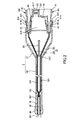
- FIG. 1 is a perspective view showing a preferred embodiment of the syringe assembly of the present invention.
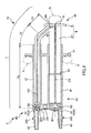
- FIG. 2 is a cross-sectional view taken along line AA in FIG.
- FIG. 3 is a diagram (partial cross-sectional view) showing an operating state of the syringe assembly shown in FIG. 1.
- FIG. 4 is a diagram (partial cross-sectional view) showing an operating state of the syringe assembly shown in FIG. 1.
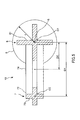
- FIG. 5 is a cross-sectional view taken along line BB in FIG.
- FIG. 1 is a perspective view showing a preferred embodiment of the syringe assembly of the present invention
- FIG. 2 is a cross-sectional view taken along line AA in FIG. 1
- FIGS. 3 and 4 are views of the syringe assembly shown in FIG.
- FIG. 5 is a cross-sectional view taken along the line BB in FIG. It is.
- the right side in FIGS. 2, 3, and 4 is referred to as “base end”
- the left side is referred to as “tip”
- the upper side is referred to as “upper”
- the lower side is referred to as “lower”.
- the applicator 1 applies two types of liquids (first liquid L1 and second liquid L2) having different liquid compositions while mixing them.
- the applicator 1 includes a first syringe 4A in which a first liquid L1 is stored, a second syringe 4B in which a second liquid L2 is stored in parallel with the first syringe 4A, and each liquid.
- Syringe connection body 2 having a pusher connection body 10 that performs an operation of discharging the liquid (hereinafter, this operation is referred to as “pressing operation”), and a nozzle 3 that discharges the liquid discharged from the syringe connection body 2 to the application target.
- pressing operation a pusher connection body 10 that performs an operation of discharging the liquid
- the nozzle 3 has a tube-shaped nozzle main body 32 and a nozzle support portion 31 that supports the proximal end portion of the nozzle main body 32 and to which the syringe connector 2 is connected.
- the applicator 1 ejects a mixture of the first liquid L1 and the second liquid L2 (hereinafter referred to as “mixture”) together with a sterile gas G (hereinafter simply referred to as “gas G”). (See FIG. 2).
- the gas G atomizes the mixture, and the mixture can be uniformly applied to a target site (target site such as an affected area).
- the gas G is supplied by a gas cylinder (gas supply means) 9.
- the gas cylinder 9 is connected to the nozzle 3 via a gas tube 93.
- the gas cylinder 9 has a cylinder main body 91 in which the internal space is filled with high-pressure (compressed) gas G, and an openable / closable cock 92 that controls supply / stop of supply of the gas G to the nozzle 3. .
- the cock 92 is used in an open state.
- the gas G include carbon dioxide.
- the nozzle support portion 31 is liquid-tight to the first connection portion 311A and the mouth portion 43 of the second syringe 4B, which are liquid-tightly connected to the mouth portion 43 of the first syringe 4A.
- a second connection portion 311B connected to the outer shape, and an outer shape in which an opening 313 into which the nozzle main body 32 is inserted is formed is formed of a casing having a substantially triangular shape.
- first connection portion 311A and the second connection portion 311B have substantially the same configuration, the first connection portion 311A will be representatively described.
- the first connecting portion 311 ⁇ / b> A has a cylindrical shape, is provided at the proximal end portion of the nozzle support portion 31, and is a portion into which the mouth portion 43 of the syringe outer tube 41 is inserted. Further, the first connecting portion 311A is provided with a hole portion 314 penetrating from the inner periphery to the outer periphery, and the claw portion 431 of the mouth portion 43 is inserted, so that the first syringe 4A and the nozzle support portion 31 Are connected (fixed).
- a protruding piece 316 is provided between the first connecting portion 311 ⁇ / b> A and the second connecting portion 311 ⁇ / b> B and has a plate shape and protrudes toward the base end side. ing.
- An engagement claw 317 is provided at the base end portion of the protruding piece 316 and is inserted into an engagement hole 23 described later of the syringe connector 2 so that the syringe connector 2 and the nozzle 3 are connected (fixed). Is done.
- the opening 313 is provided at the tip of the nozzle support 31 and the base end of the nozzle body 32 is inserted. In this inserted state, the nozzle body 32 is fixed (supported) to the nozzle support portion 31 via an adhesive, for example.
- Such a nozzle support portion 31 is made of, for example, various metal materials or various resin materials.
- the nozzle main body 32 has a tube shape, and has a nozzle head 36 having an outer diameter increased at the tip thereof. Further, a jet outlet 361 is provided at the tip, and the mixture is jetted together with the gas G from the jet outlet 361.
- the nozzle body 32 has a liquid flow path 37 constituted by a first flow path 33 through which the first liquid L1 passes and a second flow path 34 through which the second liquid L2 passes. have.
- the nozzle body 32 has a third flow path 35 through which the gas G passes.
- the first flow path 33 is configured by a lumen portion of the first inner tube 331 inserted into the nozzle body 32 and the nozzle support portion 31.
- the proximal end portion of the first inner tube 331 is liquid-tightly connected to the first connection portion 311A of the nozzle support portion 31, and the mouth portion 43 of the first syringe 4A is connected via the first connection portion 311A. Communicated with.
- the second flow path 34 is configured by a lumen portion of the second inner tube 341 inserted into the nozzle body 32 and the nozzle support portion 31.
- the proximal end portion of the second inner tube 341 is liquid-tightly connected to the second connection portion 311B of the nozzle support portion 31, and the mouth portion 43 of the second syringe 4B is connected via the second connection portion 311B. Communicated with.
- the first flow path 33 and the second flow path 34 are close to each other at their tips and merge. Thereby, the liquid flow path 37 can be provided with a merging portion 38 where the first liquid L1 and the second liquid L2 merge.
- the distal end portion 471 of the joining portion side tube 39 is fitted to the inner peripheral portion of the distal end of the nozzle head 36.
- the proximal end portion of the merging portion side tube 39 is fitted to the distal end portions of the first inner tube 331 and the second inner tube 341 constituting the first flow path 33 and the second flow path 34, respectively. is doing. Thereby, the both ends of the junction part side tube 39 are supported and fixed reliably.
- the entire tube wall of the merging portion side tube 39 is composed of a gas permeable membrane 391.
- the gas permeable membrane 391 allows the gas G in the nozzle body 32 to pass therethrough.
- the gas G can flow into the merging portion side tube 39 (merging portion 38) through the gas permeable membrane 473, and thus the inflowing gas G is mixed with the first liquid in the merging portion 38. Together with L1 and the second liquid L2, it is ejected from the ejection port 361 (see FIG. 2). Thereby, the mixture becomes mist and is applied to the affected area.
- the gas G is emitted from any portion in the circumferential direction of the merging portion side tube 39 via the gas permeable membrane 473. It can flow into the merging portion side tube 39. Thereby, the gas G can be supplied into the junction part side tube 39 without excess and deficiency, and the mixture ejected from the ejection port 361 is surely made into a mist.
- the mixture becomes mist-like, the mixture is uniformly mixed with the first liquid L1 and the second liquid L2, and is applied to the affected area in a suitable state (a state where the mixing is uniform). Is done.
- a large number of pores are formed. Each pore penetrates the gas permeable membrane 391 in the thickness direction.
- the gas G can be surely permeated and the gas permeable membrane 391 has a bacteria-impermeable property. Since the gas permeable membrane 391 is impervious to bacteria, even if the gas G in the gas cylinder 9 is not in a sterile state, fungi in the gas G are removed by the gas permeable membrane 391 and the fungi are removed from the nozzle 3. Inflow is reliably prevented. Thereby, the aseptic mixture can be applied to the affected area.
- the film thickness (wall pressure) of the gas permeable membrane 391 is not particularly limited, and is preferably, for example, 0.1 to 1 mm, and more preferably 0.3 to 0.8 mm.
- the surface area (area of the outer peripheral surface) of the gas permeable membrane 391 is preferably 20 to 200 mm 2 , and more preferably 40 to 100 mm 2 .
- the gas permeable membrane 391 is impermeable (water repellency) to the first liquid L1 and the second liquid L2, that is, has hydrophobicity. Thereby, the first liquid L1 and the second liquid L2 in the merging portion side tube 39 flow backward (flow) into the third flow path 46 (merging portion side tube 39) through the gas permeable membrane 391. Is reliably prevented.
- a gas permeable membrane 391 is made of a hydrophobic material, or the surface thereof is subjected to a hydrophobic treatment. Examples of the hydrophobic material (constituent material) include polytetrafluoroethylene (PTFE).
- the third flow path 35 through which the gas G passes includes a first inner tube 331 constituting the first flow path 33 and a second inner tube 341 constituting the second flow path 34, and an outer peripheral side thereof. It is comprised by the clearance gap between the nozzle main bodies 32 located. The base end portion of the nozzle body 32 is connected to the gas tube 93 described above.
- the nozzle 3 has a double pipe structure constituted by the first inner tube 331 and the second inner tube 341 and the nozzle body 32.
- the 1st inner tube 331 and the 2nd inner tube 341, and the nozzle main body 32 become a parallel positional relationship, and as above-mentioned, each tube can be used suitably as a flow path, respectively.
- the constituent material of each tube include various soft or hard resins such as polyvinyl chloride, polyethylene, and polypropylene, various rubber materials such as silicone rubber, and various thermoplastic elastomers such as polyurethane. .
- the first syringe 4A and the second syringe 4B have substantially the same configuration except that their maximum volumes (inner diameters) are different, the first syringe 4A will be representatively described below.
- the first syringe 4A has a maximum volume (inner diameter) larger than the maximum volume (inner diameter) of the second syringe 4B.
- the first syringe 4A has a syringe outer cylinder 41 that is a first syringe outer cylinder and a gasket 42 that is a first gasket.
- the syringe outer cylinder 41 has a bottomed cylindrical shape, and a bottom portion 44 is integrally formed with a mouth portion 43 that is a first mouth portion whose diameter is reduced with respect to the body portion of the syringe outer tube 41. .
- the mouth portion 43 has a cylindrical shape, and a claw portion 431 is provided on the outer peripheral portion thereof. The claw portion 431 is inserted into the hole portion 314 of the first connection portion 311A described above, and the syringe connector 2 and the nozzle 3 are fixed.
- a flange 21 is integrally formed on the outer periphery in the longitudinal direction of the syringe outer cylinder 41 so as to project integrally.
- the flange 21 is also provided across the outer periphery of the proximal end of the syringe outer cylinder 41 of the second syringe 4B, and the first syringe 4A and the second syringe 4B are connected in a line.
- each syringe outer cylinder 41 is also connected at the tip outer peripheral portion with a plate piece 22.
- the plate piece 22 is provided with an engagement hole 23 penetrating in the thickness direction.
- the engaging claw 317 of the nozzle 3 is inserted into the engaging hole 23, and the syringe connector 2 and the nozzle 3 are fixed.
- the constituent material of the syringe outer cylinder 41 for example, a resin such as polypropylene, cyclic polyolefin, or polyester is preferable because it is easy to mold and has low water vapor permeability.
- the constituent material of each outer cylinder 41 is substantially transparent in order to ensure internal visibility.
- a gasket 42 made of an elastic material is accommodated (inserted).
- a plurality (two) of ring-shaped protrusions are formed on the entire outer periphery of the gasket 42, and these protrusions slide while being in close contact with the inner peripheral surface of the outer cylinder 41. While maintaining liquid-tightness more reliably, slidability can be improved.
- the gasket 42 is formed with a hollow portion 421 that opens to the base end surface thereof.
- the hollow portion 421 is fitted with a head portion 63 of the first pusher 6 of the pusher connector 10 described later.
- the constituent material of the gasket 42 is not particularly limited.
- various rubber materials such as isoprene rubber, butadiene rubber and silicone rubber, various thermoplastic elastomers such as polyurethane and polyester, or elastic materials such as a mixture thereof. Materials.
- the second syringe 4B has a syringe outer cylinder 41 serving as a second syringe outer cylinder and a gasket 42 serving as a second gasket, similarly to the first syringe 4A. And when this gasket 42 moves to the front end side, the 2nd liquid L2 can be discharged
- a space (liquid storage space) surrounded by the syringe outer cylinder 41 and the gasket 42 is filled with the first liquid L1.
- the second syringe 4B has the second liquid L2 in the space (liquid storage space) surrounded by the syringe outer cylinder 41 and the gasket 42 before being connected to the nozzle 3. Filled.
- 1st liquid L1 and 2nd liquid L2 are suitably selected according to the use of the applicator 1, a purpose of use, a case, etc.
- one of the first liquid L1 and the second liquid L2 is a liquid containing thrombin (solution or the like), and the other is a liquid containing fibrinogen (solution or the like). ).
- one of the first liquid L1 and the second liquid L2 is a liquid (solution or the like) containing carboxymethyldextrin modified with a succinimidyl group, and the other is phosphorus It can be set as the liquid (solution etc.) containing disodium oxyhydrogen.
- first liquid L1 and the second liquid L2 have different viscosities.
- the viscosity of the first liquid L1 is larger than the viscosity of the second liquid.
- the first liquid L1 and the second liquid L2 in such a combination are altered, that is, gelled (solidified) when they are mixed.
- gelling for example, a mixture of the first liquid L1 and the second liquid L2 (hereinafter referred to as “mixture”) can reliably remain in the applied biological tissue (target site).
- the mixture since the mixture remains reliably at the target site, the function as a biological tissue adhesive or an adhesion preventing material can be reliably exhibited at the target site.
- first liquid L1 and the second liquid L2 are not limited to those described above.
- the inner diameter of the first syringe 4A is larger than the inner diameter of the second syringe 4B. Furthermore, the viscosity of the first liquid L1 filled in the first syringe 4A is larger than the viscosity of the second liquid L2 filled in the second syringe 4B. Moreover, the size of each mouth part 43 is the same. In combination with this, the pressing force F1 required to move the gasket 42 of the first syringe 4A when discharging the first liquid L1 is the same as that of the second syringe 4B when discharging the second liquid L2. The pressing force F2 required for the movement of the gasket 42 is larger.
- the gasket connectors 42 are collectively moved by performing a pressing operation on the pusher connector 10 with a pressing force F 0 that is the sum of the pressing force F 1 and the pressing force F 2. Let Thereby, the syringe connector 2 can discharge the first liquid L1 and the second liquid L2.
- gasket 42 of the first syringe 4A is also referred to as “gasket 42A”
- gasket 42 of the second syringe 4B is also referred to as “gasket 42B”.
- the pusher connector 10 includes a first pusher 6 connected to the gasket 42A, a second pusher 7 connected to the gasket 42B, and a first pusher 7. And an operation portion 8 provided on the extension line on the proximal end side of the pusher 6.
- a first pusher 6 connected to the gasket 42A
- a second pusher 7 connected to the gasket 42B
- a first pusher 7 connected to the gasket 42B
- an operation portion 8 provided on the extension line on the proximal end side of the pusher 6.
- the first pusher 6 has a first pusher body 61 having a linear shape and a cross-sectional shape of a cross shape.
- a flange 62 is provided in the middle of the first pusher 6 in the longitudinal direction as a reinforcing portion that reinforces the first pusher 6.
- a mushroom-like head portion (connecting portion) 63 is formed at the tip end portion of the first pusher body 61.
- the head portion 63 is fitted into the hollow portion 421 of the gasket 42 of the first syringe 4A, and the gasket 42 of the first syringe 4A and the first pusher 6 are connected.
- connection method with respect to the gasket 42 of the 1st syringe 4A of the 1st pusher 6 is not limited to the thing of illustration,
- fusion, and screwing, may be used. .
- the second pusher 7 is branched from the base end portion of the first pusher 6 and extends toward the distal end side.
- the second pusher 7 has a cross-shaped cross section. Further, the second pusher 7 has a curved portion 72 that is curved in the middle of its longitudinal direction, and a linear portion 73 that is a portion on the distal side of the curved portion 72 and a proximal end than the curved portion 72. It can be divided into an inclined portion 74 which is a side portion.
- the inclined portion 74 has a linear shape, and is inclined with respect to the linear portion 73 and the first pusher body 61.
- the angle ⁇ formed by the linear portion 73 and the first pusher body 61 is preferably an acute angle.
- the inclined portion 74 is connected to a boundary portion 64 with the operation portion 8 of the first pusher body 61. That is, the boundary portion 64 is a branch portion of the first pusher 6 and the second pusher 7.
- the curved portion 72 is a portion that is curved outward. Since the angle ⁇ formed between the inclined portion 74 and the first pusher body 61 is an acute angle, the bending portion 72 is located on the distal end side with respect to the operation portion 8. When the bending portion 72 is the same as the operation portion 8 or is located on the proximal end side with respect to the operation portion 8, the user accidentally puts a finger on the bending portion 72 and performs a pressing operation. It is possible. However, in the pusher connector 10, the operation unit 8 is located on the most distal side. Thereby, the user can press the operation part 8 reliably.
- the bending portion 72 makes it difficult for the user's finger to be applied to the second pusher 7 even when the user accidentally presses the bending portion 72. Therefore, the second pusher 7 can be shaped so as not to be pressed from the base end side. Therefore, as described above, the user can press the operation unit 8 more reliably due to a synergistic effect with the bending portion 72 being positioned on the tip side of the operation unit 8.
- the linear portion 73 is provided in parallel with the first pusher body 61. As shown in FIGS. 3 to 5, the thickness of the linear portion 73 is smaller than the thickness of the first pusher body 61. The linear portion 73 occupies most of the second pusher 7. In addition, as shown in FIG. 4, the linear portion 73 occupies most of the second pusher 7 when the second liquid L2 is completely discharged, and the linear portion 73 is the second syringe. It is stored in the syringe outer cylinder 41 of 4B. Thereby, size reduction of the syringe coupling body 2 of a discharge completion state can be achieved.
- tip part of this linear part 73 becomes the structure similar to the 1st pusher main body 61, and the gasket 42 of the 2nd syringe 4B is connected.
- the operation unit 8 is configured by a disk-shaped flange.
- This operation part 8 is a part operated when performing pressing operation.
- FIG. 3 when a pressing operation is performed, first, the index finger f 1 and the middle finger f 2 are hooked on the flange 21 connecting the syringe outer cylinders 41, and the thumb f 3 is hooked on the operation unit 8 to connect the syringes. Hold 2 Next, as shown in FIG. 4, from the state holding the syringe connecting member 2, the index finger f 1 thumb f 3 And pressed toward to the operation portion 8 on the distal end side so as to approach the middle finger f 2. In this way, the user can perform a pressing operation.
- the center S of the operation unit 8 overlaps the central axis O1 of the first pusher body 61.
- the power point of the pressing force F0 overlaps with the central axis O1 of the first pusher body 61. Therefore, the pressing force F0 is effectively transmitted to the first pusher 6 and the second pusher 7.
- the radius r of the operation portion 8 is preferably smaller than the separation distance D1 between the central axis O1 of the first pusher body 61 and the central axis O2 of the linear portion 73, and is half the length of the separation distance D1. More preferably, it is smaller than D2.
- the operation unit 8 by the size as described above, the position of the user is separated from the center S of the operation part 8, namely, to prevent the applied belly of the thumb f 3 to the edge portion of the operation portion 8 Can do. Therefore, the user can perform the pressing operation in a state where the power point of the pressing force F0 is reliably located at the center S of the operation unit 8.
- the operating portion 8 is provided on the proximal end side extension line of the first pusher 6 connected to the gasket 42A, and the second pusher 7 is A branch is provided from the first pusher 6.
- the pressing force F1 which is the majority of the pressing force F0
- the pressing force F2 is distributed and transmitted.
- the gasket 42 ⁇ / b> A is moved by the first pusher 6, and the gasket 42 ⁇ / b> B is moved by the second pusher 7. Therefore, the first liquid L1 and the second liquid L2 are discharged.
- the first pusher 6 and the second pusher are applied in accordance with the ratio of the pressing force F1 and the pressing force F2 required to move the gaskets 42 to the pressing force F0 applied to the operation unit 8. 7 and can be transmitted.
- the gasket 42 having a larger pressing force required for movement is mainly pressed. Therefore, the gasket 42 with the smaller pressing force required for movement is prevented from being mainly pressed.
- rattling of the pusher connector 10 can be prevented, and the user can perform a pressing operation stably.
- the rattling of the pusher connector 10 is prevented, the movement amount of each gasket 42 becomes the same, and as a result, the mixing ratio of each liquid becomes constant.
- the 2nd pusher is comprised by the linear part, the inclination part, and the curved part, it is not limited to this in this invention, an inclination part is abbreviate
- the proximal end side may be a curved portion up to the first pusher.
- the curved portion has a curved shape, but the present invention is not limited to this, and may be, for example, a sharply bent shape.
- the syringe assembly of the present invention has a first mouth part that is formed to protrude from the tip part, and slides in the first syringe outer cylinder filled with the first liquid and the first syringe outer cylinder.
- a first syringe that can move and has a first gasket that drains the first liquid through the first mouth by moving to the distal end;
- a second syringe outer cylinder that has a second mouth projectingly formed at the distal end and is slidable in the second syringe outer cylinder filled with the second liquid, and moves to the distal end side
- a pusher coupling body that performs a pressing operation to move the first gasket and the second gasket in a lump toward the tip direction;
- the force required to move the first gasket when discharging the first liquid is greater than the force required to move the second gasket when discharging the second liquid,
- the second pusher is provided to be branched from the first pusher having the operation portion, and the first pusher is connected to the gasket having a large pressing force required for movement. Therefore, when the pressing operation is performed, the second pusher can move together with the first pusher as much as the first pusher. Therefore, the wobbling of the pusher coupling body can be prevented during the pressing operation, and the liquid can be discharged stably.
- the first pusher when the center of the operation unit overlaps the central axis of the first pusher, the first pusher can be effectively pressed and the liquid can be discharged stably.
- the syringe assembly of the present invention has industrial applicability.
Abstract
L'invention concerne un ensemble seringue (2) qui comprend : une première seringue (4A) qui a un cylindre extérieur de seringue (41) rempli d'un premier liquide (L1) et qui comprend également un joint d'étanchéité (42A) ; une seconde seringue (4B) qui a un cylindre extérieur de seringue (41) rempli d'un second liquide (L2) et qui comprend également un joint d'étanchéité (42B) ; et un ensemble poussoir (10) qui réalise une opération de poussée pour déplacer collectivement les joints d'étanchéité (42A, 42B). L'ensemble poussoir (10) comprend : un premier poussoir (6) qui a une extrémité avant reliée au joint d'étanchéité (42A) ; un second poussoir (7) qui est dérivé à partir du premier poussoir (6), s'étend vers le côté d'extrémité avant et a une extrémité avant reliée au joint d'étanchéité (42B) ; et une section d'actionnement (8) qui est située sur une ligne s'étendant à partir du côté d'extrémité de base du premier poussoir (6) et qui est actionnée pour l'opération de poussée.
Priority Applications (4)
| Application Number | Priority Date | Filing Date | Title |
|---|---|---|---|
| JP2015524968A JP6246205B2 (ja) | 2013-07-04 | 2013-07-04 | シリンジ連結体 |
| PCT/JP2013/068329 WO2015001638A1 (fr) | 2013-07-04 | 2013-07-04 | Ensemble seringue |
| EP13888550.4A EP3017773B1 (fr) | 2013-07-04 | 2013-07-04 | Ensemble seringue |
| US14/987,242 US10449295B2 (en) | 2013-07-04 | 2016-01-04 | Syringe assembly |
Applications Claiming Priority (1)
| Application Number | Priority Date | Filing Date | Title |
|---|---|---|---|
| PCT/JP2013/068329 WO2015001638A1 (fr) | 2013-07-04 | 2013-07-04 | Ensemble seringue |
Related Child Applications (1)
| Application Number | Title | Priority Date | Filing Date |
|---|---|---|---|
| US14/987,242 Continuation US10449295B2 (en) | 2013-07-04 | 2016-01-04 | Syringe assembly |
Publications (1)
| Publication Number | Publication Date |
|---|---|
| WO2015001638A1 true WO2015001638A1 (fr) | 2015-01-08 |
Family
ID=52143258
Family Applications (1)
| Application Number | Title | Priority Date | Filing Date |
|---|---|---|---|
| PCT/JP2013/068329 WO2015001638A1 (fr) | 2013-07-04 | 2013-07-04 | Ensemble seringue |
Country Status (4)
| Country | Link |
|---|---|
| US (1) | US10449295B2 (fr) |
| EP (1) | EP3017773B1 (fr) |
| JP (1) | JP6246205B2 (fr) |
| WO (1) | WO2015001638A1 (fr) |
Cited By (2)
| Publication number | Priority date | Publication date | Assignee | Title |
|---|---|---|---|---|
| US9572555B1 (en) | 2015-09-24 | 2017-02-21 | Ethicon, Inc. | Spray or drip tips having multiple outlet channels |
| EP3225173A1 (fr) * | 2016-03-31 | 2017-10-04 | Terumo Kabushiki Kaisha | Applicateur |
Families Citing this family (2)
| Publication number | Priority date | Publication date | Assignee | Title |
|---|---|---|---|---|
| USD877891S1 (en) * | 2015-12-22 | 2020-03-10 | Guangzhou Bioseal Biotech Co., Ltd. | Reconstitution and delivery device |
| USD877890S1 (en) * | 2015-12-22 | 2020-03-10 | Guangzhou Bioseal Biotech Co., Ltd. | Reconstitution device |
Citations (3)
| Publication number | Priority date | Publication date | Assignee | Title |
|---|---|---|---|---|
| JP2009131590A (ja) | 2007-11-08 | 2009-06-18 | Terumo Corp | 塗布具 |
| JP2009240427A (ja) * | 2008-03-28 | 2009-10-22 | Terumo Corp | 塗布具 |
| US20100310782A1 (en) * | 2009-05-06 | 2010-12-09 | Kortney Wawrzyniak | Method and apparatus for applying a sealant |
Family Cites Families (9)
| Publication number | Priority date | Publication date | Assignee | Title |
|---|---|---|---|---|
| AT382783B (de) * | 1985-06-20 | 1987-04-10 | Immuno Ag | Vorrichtung zur applikation eines gewebeklebstoffes |
| EP1208918B1 (fr) * | 2000-09-25 | 2003-05-02 | Ernst Mühlbauer GmbH & Co.KG | Dispositif de décharge à proportion constante de deux substances fluides,en particulier dans le domaine dentaire |
| US8545457B2 (en) | 2007-11-08 | 2013-10-01 | Terumo Kabushiki Kaisha | Sprayer |
| EP2679170A4 (fr) * | 2011-02-25 | 2015-06-24 | Terumo Corp | Applicateur |
| WO2012124595A1 (fr) * | 2011-03-17 | 2012-09-20 | テルモ株式会社 | Applicateur et procédé d'application |
| EP2692380B1 (fr) * | 2011-03-29 | 2018-04-25 | Terumo Kabushiki Kaisha | Seringue |
| EP2776089A4 (fr) * | 2011-11-08 | 2015-03-18 | David R Duncan | Dispositif de perfusion de médicament compact non électrique |
| US9981082B2 (en) * | 2015-09-16 | 2018-05-29 | Tyler G. Fish | Medical infusion pump for sequentially injecting solutions from multiple syringes |
| JP2017176713A (ja) * | 2016-03-31 | 2017-10-05 | テルモ株式会社 | 塗布具 |
-
2013
- 2013-07-04 JP JP2015524968A patent/JP6246205B2/ja active Active
- 2013-07-04 EP EP13888550.4A patent/EP3017773B1/fr active Active
- 2013-07-04 WO PCT/JP2013/068329 patent/WO2015001638A1/fr active Application Filing
-
2016
- 2016-01-04 US US14/987,242 patent/US10449295B2/en active Active
Patent Citations (3)
| Publication number | Priority date | Publication date | Assignee | Title |
|---|---|---|---|---|
| JP2009131590A (ja) | 2007-11-08 | 2009-06-18 | Terumo Corp | 塗布具 |
| JP2009240427A (ja) * | 2008-03-28 | 2009-10-22 | Terumo Corp | 塗布具 |
| US20100310782A1 (en) * | 2009-05-06 | 2010-12-09 | Kortney Wawrzyniak | Method and apparatus for applying a sealant |
Non-Patent Citations (1)
| Title |
|---|
| See also references of EP3017773A4 |
Cited By (5)
| Publication number | Priority date | Publication date | Assignee | Title |
|---|---|---|---|---|
| US9572555B1 (en) | 2015-09-24 | 2017-02-21 | Ethicon, Inc. | Spray or drip tips having multiple outlet channels |
| WO2017053107A1 (fr) * | 2015-09-24 | 2017-03-30 | Ethicon, Inc. | Pointes de pulvérisation ou de goutte-à-goutte dotées de multiples canaux de sortie |
| EP3225173A1 (fr) * | 2016-03-31 | 2017-10-04 | Terumo Kabushiki Kaisha | Applicateur |
| EP3225172A1 (fr) * | 2016-03-31 | 2017-10-04 | Terumo Kabushiki Kaisha | Applicateur |
| JP2017176713A (ja) * | 2016-03-31 | 2017-10-05 | テルモ株式会社 | 塗布具 |
Also Published As
| Publication number | Publication date |
|---|---|
| US10449295B2 (en) | 2019-10-22 |
| EP3017773A1 (fr) | 2016-05-11 |
| US20160113639A1 (en) | 2016-04-28 |
| EP3017773B1 (fr) | 2023-07-19 |
| JP6246205B2 (ja) | 2017-12-13 |
| JPWO2015001638A1 (ja) | 2017-02-23 |
| EP3017773A4 (fr) | 2017-03-29 |
Similar Documents
| Publication | Publication Date | Title |
|---|---|---|
| JP6636507B2 (ja) | 液体並びに粉末止血剤及びシーラントを共送達するための方法及び装置 | |
| EP2111918B1 (fr) | Buse de pulvérisation en silicone | |
| JP2017176713A (ja) | 塗布具 | |
| US20140012212A1 (en) | Sprayer | |
| JP5222591B2 (ja) | 塗布具 | |
| JP6246205B2 (ja) | シリンジ連結体 | |
| JP5138683B2 (ja) | スプレーヘッド、生体組織接着剤塗布器具、および接着剤の塗布方法 | |
| CA2884662C (fr) | Ensemble embout sans air et anti-obstruction et dispositif associe | |
| JP4486036B2 (ja) | 塗布具 | |
| US20120330229A1 (en) | Syringe-like mixing device having a distally operable mixing element | |
| US20160113640A1 (en) | Applicator | |
| JP2009131590A (ja) | 塗布具 | |
| JP2010075412A (ja) | 塗布具 | |
| JP5588131B2 (ja) | 液状体供給具 | |
| JP5255386B2 (ja) | 塗布具 | |
| JP6095693B2 (ja) | 塗布具 | |
| JP4110569B2 (ja) | プレフィルドシリンジキット | |
| JP2008307227A (ja) | 塗布具 | |
| CN113518589B (zh) | 生物体接合剂涂布工具 | |
| JP2006095098A (ja) | 投与器具 | |
| JP2009006120A (ja) | 塗布具 | |
| JP2010023021A (ja) | 塗布方法 | |
| JP2009207513A (ja) | 塗布具 | |
| US20140121698A1 (en) | System for storing and dispensing multiple fluids and a method for using the same | |
| JP2015144676A (ja) | シリンジ連結体 |
Legal Events
| Date | Code | Title | Description |
|---|---|---|---|
| 121 | Ep: the epo has been informed by wipo that ep was designated in this application |
Ref document number: 13888550 Country of ref document: EP Kind code of ref document: A1 |
|
| ENP | Entry into the national phase |
Ref document number: 2015524968 Country of ref document: JP Kind code of ref document: A |
|
| WWE | Wipo information: entry into national phase |
Ref document number: 2013888550 Country of ref document: EP |
|
| NENP | Non-entry into the national phase |
Ref country code: DE |