WO2014208938A1 - 열 회수 장치 - Google Patents
열 회수 장치 Download PDFInfo
- Publication number
- WO2014208938A1 WO2014208938A1 PCT/KR2014/005474 KR2014005474W WO2014208938A1 WO 2014208938 A1 WO2014208938 A1 WO 2014208938A1 KR 2014005474 W KR2014005474 W KR 2014005474W WO 2014208938 A1 WO2014208938 A1 WO 2014208938A1
- Authority
- WO
- WIPO (PCT)
- Prior art keywords
- heat exchanger
- heat
- refrigerant flow
- steam
- flowing out
- Prior art date
Links
- 238000011084 recovery Methods 0.000 title claims abstract description 81
- 238000000034 method Methods 0.000 claims abstract description 51
- 239000002918 waste heat Substances 0.000 claims abstract description 29
- 239000003507 refrigerant Substances 0.000 claims description 176
- 239000012530 fluid Substances 0.000 claims description 67
- XLYOFNOQVPJJNP-UHFFFAOYSA-N water Substances O XLYOFNOQVPJJNP-UHFFFAOYSA-N 0.000 claims description 22
- 238000004519 manufacturing process Methods 0.000 abstract description 11
- 238000001311 chemical methods and process Methods 0.000 abstract description 6
- 238000004821 distillation Methods 0.000 abstract description 5
- 239000003208 petroleum Substances 0.000 abstract 1
- 239000000126 substance Substances 0.000 abstract 1
- 239000007789 gas Substances 0.000 description 37
- 239000007788 liquid Substances 0.000 description 14
- 238000007906 compression Methods 0.000 description 7
- 230000006835 compression Effects 0.000 description 6
- 230000000052 comparative effect Effects 0.000 description 5
- 238000010586 diagram Methods 0.000 description 5
- RWGFKTVRMDUZSP-UHFFFAOYSA-N cumene Chemical compound CC(C)C1=CC=CC=C1 RWGFKTVRMDUZSP-UHFFFAOYSA-N 0.000 description 4
- 239000007791 liquid phase Substances 0.000 description 4
- 239000012071 phase Substances 0.000 description 3
- SMZOUWXMTYCWNB-UHFFFAOYSA-N 2-(2-methoxy-5-methylphenyl)ethanamine Chemical compound COC1=CC=C(C)C=C1CCN SMZOUWXMTYCWNB-UHFFFAOYSA-N 0.000 description 2
- NIXOWILDQLNWCW-UHFFFAOYSA-N 2-Propenoic acid Natural products OC(=O)C=C NIXOWILDQLNWCW-UHFFFAOYSA-N 0.000 description 2
- LRHPLDYGYMQRHN-UHFFFAOYSA-N N-Butanol Chemical compound CCCCO LRHPLDYGYMQRHN-UHFFFAOYSA-N 0.000 description 2
- 238000006243 chemical reaction Methods 0.000 description 2
- 238000009434 installation Methods 0.000 description 2
- MSSNHSVIGIHOJA-UHFFFAOYSA-N pentafluoropropane Chemical compound FC(F)CC(F)(F)F MSSNHSVIGIHOJA-UHFFFAOYSA-N 0.000 description 2
- FNYLWPVRPXGIIP-UHFFFAOYSA-N Triamterene Chemical compound NC1=NC2=NC(N)=NC(N)=C2N=C1C1=CC=CC=C1 FNYLWPVRPXGIIP-UHFFFAOYSA-N 0.000 description 1
- 239000006096 absorbing agent Substances 0.000 description 1
- 238000005804 alkylation reaction Methods 0.000 description 1
- 230000004075 alteration Effects 0.000 description 1
- 238000009833 condensation Methods 0.000 description 1
- 230000005494 condensation Effects 0.000 description 1
- 239000002826 coolant Substances 0.000 description 1
- 239000000498 cooling water Substances 0.000 description 1
- 238000007599 discharging Methods 0.000 description 1
- 238000005265 energy consumption Methods 0.000 description 1
- 239000007792 gaseous phase Substances 0.000 description 1
- 238000010438 heat treatment Methods 0.000 description 1
- 238000010248 power generation Methods 0.000 description 1
- 238000009834 vaporization Methods 0.000 description 1
- 230000008016 vaporization Effects 0.000 description 1
Images
Classifications
-
- F—MECHANICAL ENGINEERING; LIGHTING; HEATING; WEAPONS; BLASTING
- F25—REFRIGERATION OR COOLING; COMBINED HEATING AND REFRIGERATION SYSTEMS; HEAT PUMP SYSTEMS; MANUFACTURE OR STORAGE OF ICE; LIQUEFACTION SOLIDIFICATION OF GASES
- F25B—REFRIGERATION MACHINES, PLANTS OR SYSTEMS; COMBINED HEATING AND REFRIGERATION SYSTEMS; HEAT PUMP SYSTEMS
- F25B27/00—Machines, plants or systems, using particular sources of energy
- F25B27/02—Machines, plants or systems, using particular sources of energy using waste heat, e.g. from internal-combustion engines
-
- F—MECHANICAL ENGINEERING; LIGHTING; HEATING; WEAPONS; BLASTING
- F28—HEAT EXCHANGE IN GENERAL
- F28C—HEAT-EXCHANGE APPARATUS, NOT PROVIDED FOR IN ANOTHER SUBCLASS, IN WHICH THE HEAT-EXCHANGE MEDIA COME INTO DIRECT CONTACT WITHOUT CHEMICAL INTERACTION
- F28C3/00—Other direct-contact heat-exchange apparatus
- F28C3/04—Other direct-contact heat-exchange apparatus the heat-exchange media both being liquids
-
- B—PERFORMING OPERATIONS; TRANSPORTING
- B01—PHYSICAL OR CHEMICAL PROCESSES OR APPARATUS IN GENERAL
- B01D—SEPARATION
- B01D3/00—Distillation or related exchange processes in which liquids are contacted with gaseous media, e.g. stripping
- B01D3/007—Energy recuperation; Heat pumps
-
- F—MECHANICAL ENGINEERING; LIGHTING; HEATING; WEAPONS; BLASTING
- F24—HEATING; RANGES; VENTILATING
- F24H—FLUID HEATERS, e.g. WATER OR AIR HEATERS, HAVING HEAT-GENERATING MEANS, e.g. HEAT PUMPS, IN GENERAL
- F24H4/00—Fluid heaters characterised by the use of heat pumps
- F24H4/02—Water heaters
- F24H4/04—Storage heaters
-
- F—MECHANICAL ENGINEERING; LIGHTING; HEATING; WEAPONS; BLASTING
- F25—REFRIGERATION OR COOLING; COMBINED HEATING AND REFRIGERATION SYSTEMS; HEAT PUMP SYSTEMS; MANUFACTURE OR STORAGE OF ICE; LIQUEFACTION SOLIDIFICATION OF GASES
- F25B—REFRIGERATION MACHINES, PLANTS OR SYSTEMS; COMBINED HEATING AND REFRIGERATION SYSTEMS; HEAT PUMP SYSTEMS
- F25B1/00—Compression machines, plants or systems with non-reversible cycle
- F25B1/10—Compression machines, plants or systems with non-reversible cycle with multi-stage compression
-
- F—MECHANICAL ENGINEERING; LIGHTING; HEATING; WEAPONS; BLASTING
- F25—REFRIGERATION OR COOLING; COMBINED HEATING AND REFRIGERATION SYSTEMS; HEAT PUMP SYSTEMS; MANUFACTURE OR STORAGE OF ICE; LIQUEFACTION SOLIDIFICATION OF GASES
- F25B—REFRIGERATION MACHINES, PLANTS OR SYSTEMS; COMBINED HEATING AND REFRIGERATION SYSTEMS; HEAT PUMP SYSTEMS
- F25B27/00—Machines, plants or systems, using particular sources of energy
-
- F—MECHANICAL ENGINEERING; LIGHTING; HEATING; WEAPONS; BLASTING
- F25—REFRIGERATION OR COOLING; COMBINED HEATING AND REFRIGERATION SYSTEMS; HEAT PUMP SYSTEMS; MANUFACTURE OR STORAGE OF ICE; LIQUEFACTION SOLIDIFICATION OF GASES
- F25B—REFRIGERATION MACHINES, PLANTS OR SYSTEMS; COMBINED HEATING AND REFRIGERATION SYSTEMS; HEAT PUMP SYSTEMS
- F25B30/00—Heat pumps
- F25B30/02—Heat pumps of the compression type
-
- F—MECHANICAL ENGINEERING; LIGHTING; HEATING; WEAPONS; BLASTING
- F24—HEATING; RANGES; VENTILATING
- F24D—DOMESTIC- OR SPACE-HEATING SYSTEMS, e.g. CENTRAL HEATING SYSTEMS; DOMESTIC HOT-WATER SUPPLY SYSTEMS; ELEMENTS OR COMPONENTS THEREFOR
- F24D2200/00—Heat sources or energy sources
- F24D2200/16—Waste heat
-
- F—MECHANICAL ENGINEERING; LIGHTING; HEATING; WEAPONS; BLASTING
- F25—REFRIGERATION OR COOLING; COMBINED HEATING AND REFRIGERATION SYSTEMS; HEAT PUMP SYSTEMS; MANUFACTURE OR STORAGE OF ICE; LIQUEFACTION SOLIDIFICATION OF GASES
- F25B—REFRIGERATION MACHINES, PLANTS OR SYSTEMS; COMBINED HEATING AND REFRIGERATION SYSTEMS; HEAT PUMP SYSTEMS
- F25B2339/00—Details of evaporators; Details of condensers
- F25B2339/04—Details of condensers
- F25B2339/047—Water-cooled condensers
-
- F—MECHANICAL ENGINEERING; LIGHTING; HEATING; WEAPONS; BLASTING
- F25—REFRIGERATION OR COOLING; COMBINED HEATING AND REFRIGERATION SYSTEMS; HEAT PUMP SYSTEMS; MANUFACTURE OR STORAGE OF ICE; LIQUEFACTION SOLIDIFICATION OF GASES
- F25B—REFRIGERATION MACHINES, PLANTS OR SYSTEMS; COMBINED HEATING AND REFRIGERATION SYSTEMS; HEAT PUMP SYSTEMS
- F25B25/00—Machines, plants or systems, using a combination of modes of operation covered by two or more of the groups F25B1/00 - F25B23/00
- F25B25/005—Machines, plants or systems, using a combination of modes of operation covered by two or more of the groups F25B1/00 - F25B23/00 using primary and secondary systems
-
- F—MECHANICAL ENGINEERING; LIGHTING; HEATING; WEAPONS; BLASTING
- F25—REFRIGERATION OR COOLING; COMBINED HEATING AND REFRIGERATION SYSTEMS; HEAT PUMP SYSTEMS; MANUFACTURE OR STORAGE OF ICE; LIQUEFACTION SOLIDIFICATION OF GASES
- F25B—REFRIGERATION MACHINES, PLANTS OR SYSTEMS; COMBINED HEATING AND REFRIGERATION SYSTEMS; HEAT PUMP SYSTEMS
- F25B27/00—Machines, plants or systems, using particular sources of energy
- F25B27/002—Machines, plants or systems, using particular sources of energy using solar energy
- F25B27/005—Machines, plants or systems, using particular sources of energy using solar energy in compression type systems
-
- F—MECHANICAL ENGINEERING; LIGHTING; HEATING; WEAPONS; BLASTING
- F25—REFRIGERATION OR COOLING; COMBINED HEATING AND REFRIGERATION SYSTEMS; HEAT PUMP SYSTEMS; MANUFACTURE OR STORAGE OF ICE; LIQUEFACTION SOLIDIFICATION OF GASES
- F25B—REFRIGERATION MACHINES, PLANTS OR SYSTEMS; COMBINED HEATING AND REFRIGERATION SYSTEMS; HEAT PUMP SYSTEMS
- F25B2700/00—Sensing or detecting of parameters; Sensors therefor
- F25B2700/19—Pressures
- F25B2700/193—Pressures of the compressor
- F25B2700/1931—Discharge pressures
-
- F—MECHANICAL ENGINEERING; LIGHTING; HEATING; WEAPONS; BLASTING
- F25—REFRIGERATION OR COOLING; COMBINED HEATING AND REFRIGERATION SYSTEMS; HEAT PUMP SYSTEMS; MANUFACTURE OR STORAGE OF ICE; LIQUEFACTION SOLIDIFICATION OF GASES
- F25B—REFRIGERATION MACHINES, PLANTS OR SYSTEMS; COMBINED HEATING AND REFRIGERATION SYSTEMS; HEAT PUMP SYSTEMS
- F25B2700/00—Sensing or detecting of parameters; Sensors therefor
- F25B2700/19—Pressures
- F25B2700/197—Pressures of the evaporator
-
- F—MECHANICAL ENGINEERING; LIGHTING; HEATING; WEAPONS; BLASTING
- F25—REFRIGERATION OR COOLING; COMBINED HEATING AND REFRIGERATION SYSTEMS; HEAT PUMP SYSTEMS; MANUFACTURE OR STORAGE OF ICE; LIQUEFACTION SOLIDIFICATION OF GASES
- F25B—REFRIGERATION MACHINES, PLANTS OR SYSTEMS; COMBINED HEATING AND REFRIGERATION SYSTEMS; HEAT PUMP SYSTEMS
- F25B2700/00—Sensing or detecting of parameters; Sensors therefor
- F25B2700/21—Temperatures
- F25B2700/2115—Temperatures of a compressor or the drive means therefor
- F25B2700/21152—Temperatures of a compressor or the drive means therefor at the discharge side of the compressor
-
- F—MECHANICAL ENGINEERING; LIGHTING; HEATING; WEAPONS; BLASTING
- F25—REFRIGERATION OR COOLING; COMBINED HEATING AND REFRIGERATION SYSTEMS; HEAT PUMP SYSTEMS; MANUFACTURE OR STORAGE OF ICE; LIQUEFACTION SOLIDIFICATION OF GASES
- F25B—REFRIGERATION MACHINES, PLANTS OR SYSTEMS; COMBINED HEATING AND REFRIGERATION SYSTEMS; HEAT PUMP SYSTEMS
- F25B2700/00—Sensing or detecting of parameters; Sensors therefor
- F25B2700/21—Temperatures
- F25B2700/2116—Temperatures of a condenser
- F25B2700/21161—Temperatures of a condenser of the fluid heated by the condenser
-
- F—MECHANICAL ENGINEERING; LIGHTING; HEATING; WEAPONS; BLASTING
- F25—REFRIGERATION OR COOLING; COMBINED HEATING AND REFRIGERATION SYSTEMS; HEAT PUMP SYSTEMS; MANUFACTURE OR STORAGE OF ICE; LIQUEFACTION SOLIDIFICATION OF GASES
- F25B—REFRIGERATION MACHINES, PLANTS OR SYSTEMS; COMBINED HEATING AND REFRIGERATION SYSTEMS; HEAT PUMP SYSTEMS
- F25B2700/00—Sensing or detecting of parameters; Sensors therefor
- F25B2700/21—Temperatures
- F25B2700/2117—Temperatures of an evaporator
- F25B2700/21174—Temperatures of an evaporator of the refrigerant at the inlet of the evaporator
-
- F—MECHANICAL ENGINEERING; LIGHTING; HEATING; WEAPONS; BLASTING
- F25—REFRIGERATION OR COOLING; COMBINED HEATING AND REFRIGERATION SYSTEMS; HEAT PUMP SYSTEMS; MANUFACTURE OR STORAGE OF ICE; LIQUEFACTION SOLIDIFICATION OF GASES
- F25B—REFRIGERATION MACHINES, PLANTS OR SYSTEMS; COMBINED HEATING AND REFRIGERATION SYSTEMS; HEAT PUMP SYSTEMS
- F25B2700/00—Sensing or detecting of parameters; Sensors therefor
- F25B2700/21—Temperatures
- F25B2700/2117—Temperatures of an evaporator
- F25B2700/21175—Temperatures of an evaporator of the refrigerant at the outlet of the evaporator
-
- Y—GENERAL TAGGING OF NEW TECHNOLOGICAL DEVELOPMENTS; GENERAL TAGGING OF CROSS-SECTIONAL TECHNOLOGIES SPANNING OVER SEVERAL SECTIONS OF THE IPC; TECHNICAL SUBJECTS COVERED BY FORMER USPC CROSS-REFERENCE ART COLLECTIONS [XRACs] AND DIGESTS
- Y02—TECHNOLOGIES OR APPLICATIONS FOR MITIGATION OR ADAPTATION AGAINST CLIMATE CHANGE
- Y02A—TECHNOLOGIES FOR ADAPTATION TO CLIMATE CHANGE
- Y02A30/00—Adapting or protecting infrastructure or their operation
- Y02A30/27—Relating to heating, ventilation or air conditioning [HVAC] technologies
- Y02A30/274—Relating to heating, ventilation or air conditioning [HVAC] technologies using waste energy, e.g. from internal combustion engine
-
- Y—GENERAL TAGGING OF NEW TECHNOLOGICAL DEVELOPMENTS; GENERAL TAGGING OF CROSS-SECTIONAL TECHNOLOGIES SPANNING OVER SEVERAL SECTIONS OF THE IPC; TECHNICAL SUBJECTS COVERED BY FORMER USPC CROSS-REFERENCE ART COLLECTIONS [XRACs] AND DIGESTS
- Y02—TECHNOLOGIES OR APPLICATIONS FOR MITIGATION OR ADAPTATION AGAINST CLIMATE CHANGE
- Y02P—CLIMATE CHANGE MITIGATION TECHNOLOGIES IN THE PRODUCTION OR PROCESSING OF GOODS
- Y02P20/00—Technologies relating to chemical industry
- Y02P20/10—Process efficiency
-
- Y—GENERAL TAGGING OF NEW TECHNOLOGICAL DEVELOPMENTS; GENERAL TAGGING OF CROSS-SECTIONAL TECHNOLOGIES SPANNING OVER SEVERAL SECTIONS OF THE IPC; TECHNICAL SUBJECTS COVERED BY FORMER USPC CROSS-REFERENCE ART COLLECTIONS [XRACs] AND DIGESTS
- Y02—TECHNOLOGIES OR APPLICATIONS FOR MITIGATION OR ADAPTATION AGAINST CLIMATE CHANGE
- Y02P—CLIMATE CHANGE MITIGATION TECHNOLOGIES IN THE PRODUCTION OR PROCESSING OF GOODS
- Y02P70/00—Climate change mitigation technologies in the production process for final industrial or consumer products
- Y02P70/10—Greenhouse gas [GHG] capture, material saving, heat recovery or other energy efficient measures, e.g. motor control, characterised by manufacturing processes, e.g. for rolling metal or metal working
Definitions
- the present application relates to a heat recovery apparatus and method.
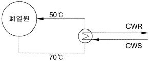
- heat exchange takes place at various routes through a reactor or distillation column, and the waste heat generated after such heat exchange can be reused or discarded.
- the waste heat is a lower heat source in the sensible state of 70 °C or more, for example, 70 to 90 °C level, the temperature is too low to be practically reusable, and therefore by condensate It is thrown away after condensation.
- hot steam is mainly used.
- the hot steam is generally heated to the vaporization point of the water of normal pressure and room temperature, by applying a high pressure to the water turned into steam to increase the internal energy to produce hot steam, in this case, the liquid water In order to vaporize, a large amount of energy consumption is required.
- the present application provides a heat recovery apparatus and method.
- the present application relates to a heat recovery device.
- the heat recovery apparatus of the present application by using the waste heat of the low-grade heat source of sensible heat of 70 °C or more discharged from industrial sites or various chemical processes, for example, the manufacturing process of petrochemical products, 1 It can be produced using only the heat exchanger of the machine, and since the generated steam can be used in various processes, it is possible to reduce the amount of hot steam, which is an external heat source for use in a reactor or a distillation column, to maximize energy saving efficiency. .
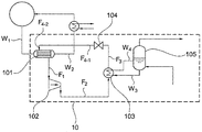
- FIG. 2 is a diagram schematically showing an exemplary heat recovery apparatus 10 of the present application.
- the heat recovery device 10 of the present application includes a first heat exchanger 101, a compressor 102, a second heat exchanger 103, and a pressure drop device 104.
- the first heat exchanger 101, the compressor 102, the second heat exchanger 103 and the pressure drop device 104 may be connected through a pipe, preferably a refrigerant or fluid flows through the pipe. It may be fluidically connected.
- the pipe through which the refrigerant flows may be a circulation loop or a circulation system connected to sequentially cycle the first heat exchanger 101, the compressor 102, the second heat exchanger 103, and the pressure drop device 104. .
- the flow rate of the refrigerant flow circulating through the pipe may be 5,000 kg / hr to 231,000 kg / hr, for example, 10,000 kg / hr to 150,000 kg / hr or 30,000 kg / hr to 200,000 kg / hr, preferably May be 25,000 kg / hr to 100,000 kg / hr, but is not limited thereto.
- the first heat exchanger 101 is included in the heat recovery device 10 of the present application for heat-exchanging a refrigerant flow and a fluid flow introduced from the outside, and through the heat exchange, the refrigerant is vaporized after the first heat exchanger.
- the gas may flow out of the first heat exchanger 101 in a gaseous flow relatively hotter than the refrigerant flow flowing into the heat exchanger.
- gas phase refers to a state in which a gas component flow is rich in all components of the refrigerant flow, for example, a state in which the mole fraction of the gas component flow in the components of the refrigerant flow is 0.9 to 1.0.
- the fluid stream W 1 flowing into the first heat exchanger 101 may be, for example, a waste heat stream or a flow of condensate passing through the condenser, and the waste heat flow may be, for example, cooling water of an exothermic reactor. May be, but is not limited now.
- a refrigerant flow (F 4-2 ) and a fluid flow (W 1 ), for example, waste heat flow, may be introduced into the first heat exchanger 101 through the fluidly connected pipe.
- the flow F 4-2 and the fluid flow W 1 may be respectively discharged from the first heat exchanger 101 through the fluidly connected pipe.
- the temperature of the refrigerant flow F 4-2 flowing into the first heat exchanger 101 is lower than the temperature of the fluid flow W 1 flowing into the first heat exchanger 101, for example, 60 ° C to 95 ° C, 70 ° C to 80 ° C, 75 ° C to 85 ° C, or 73 ° C to 77 ° C, but is not limited thereto.
- the pressure of the refrigerant flows (F 4-2 , F 1 ) flowing into and out of the first heat exchanger 101 may vary depending on the type of refrigerant and operating conditions, and is not particularly limited.
- the pressure of the refrigerant flows (F 4-2 , F 1 ) flowing into and out of the first heat exchanger 101 is 3.0 kgf / cm 2 g to 20.0 kgf / cm 2 g, for example, 4.0 kgf / cm 2 g to 10.0 kgf / cm 2 g or 5.0 kgf / cm 2 g to 7.0 kgf / cm 2 g, but is not limited thereto.
- the pressure of the refrigerant flow By adjusting the pressure of the refrigerant flow to 3.0 kgf / cm 2 g to 20.0 kgf / cm 2 g, it is possible to easily adjust the compression ratio of the compressor.
- the outflow pressure of the compressor is determined according to the temperature, but when the inflow pressure is high, the compression ratio can be kept low.
- the compression ratio is higher, it is possible to generate hot steam from a low temperature heat source, but in this case, the coefficient of performance is reduced, and as the compression ratio is lower, the coefficient of performance increases but to generate hot steam from a low temperature heat source. Difficult problems arise.
- the pressure of the fluid flows W 1 and W 2 flowing into and out of the first heat exchanger 101 is not particularly limited.
- 0.5 kgf / cm 2 g to 2.0 kgf / cm 2 g For example, it may be 0.7 kgf / cm 2 g to 1.5 kgf / cm 2 g or 0.8 kgf / cm 2 g to 1.2 kgf / cm 2 g.
- the flow rate of the fluid flow (W 1 ) flowing into the first heat exchanger 101 may be 50,000 kg / hr or more, for example, 100,000 kg / hr or more, or 1,000,000 kg / hr or more. , 500,000 kg / hr or more, but is not limited thereto.
- the outlet temperature of the fluid stream W 2 flowing out after heat transfer is maintained even if the same amount of heat is transferred to the refrigerant,
- the outlet temperature of the refrigerant flow F 1 flowing out of the heat exchanger can also be kept high.
- the upper limit of the flow rate of the fluid flow W 1 flowing into the first heat exchanger 101 is not particularly limited, and considering the efficiency and economic efficiency of the apparatus, for example, 2,300,000 kg / hr or less, Or 1,000,000 kg / hr or less, but is not limited thereto.
- the first heat exchanger 101 refers to an apparatus or a machine for performing heat exchange between flowing fluids.
- the first heat exchanger 101 is configured to evaporate a liquid refrigerant flow into a gaseous refrigerant flow. It may be an evaporator.
- the compressor 102 is included in the heat recovery device 10 of the present application in order to compress the refrigerant flow F 1 flowing out of the first heat exchanger 101 and increase the temperature and the pressure.
- the refrigerant flow F 2 which is compressed through the 102 and flows out from the first heat exchanger, may be introduced into the second heat exchanger 103, which will be described later.
- the refrigerant flow F 1 flowing out of the first heat exchanger 101 may be introduced into the compressor 102 through a fluidly connected pipe, and the refrigerant flow F 1 may be introduced into the compressor (F 1 ). After being compressed at 102, it may flow out through the fluidly connected tubing.
- the ratio of the pressure of the refrigerant flow (F 1 ) flowing out of the first heat exchanger 101 and the pressure of the refrigerant flow (F 2 ) flowing out of the compressor 102 may satisfy the following general formula (1). have.
- P C represents the pressure of the refrigerant flow F 2 flowing out of the compressor 102
- P H represents the pressure of the refrigerant flow F 1 flowing out of the first heat exchanger 101.
- the ratio P C / P H between the pressure of the refrigerant flow F 1 flowing out of the first heat exchanger 101 and the pressure of the refrigerant flow F 2 flowing out of the compressor 102 is 2 to 5, eg
- it can be adjusted in the range of 2 to 4, preferably 3 to 4.
- the ratio of the pressure of the refrigerant flow (F 1 ) flowing out of the first heat exchanger 101 and the pressure of the refrigerant flow (F 2 ) flowing out of the compressor 102 satisfies the general formula 1, whereby the first heat exchanger
- the refrigerant vaporized at 101 may be compressed to a high temperature and a high pressure state to have a sufficient amount of heat to be heat exchanged with the fluid flow passing through the second heat exchanger, which will be described later.
- the ratio of the pressure of the refrigerant flow F 1 flowing out of the first heat exchanger 101 and the pressure of the refrigerant flow F 2 flowing out of the compressor 102 is in the above range.
- the pressure of the refrigerant flow F 1 flowing out of the first heat exchanger 101 and the pressure of the refrigerant flow F 2 flowing out of the compressor 102 are not particularly limited as long as the general formula 1 is satisfied. It can be variously adjusted according to the type of process to be applied and the conditions of each process.
- the pressure of the outlet refrigerant flow F 1 is between 3.0 kgf / cm 2 g and 20.0 kgf / cm 2 g, for example 4.0 kgf / cm 2 g To 15.0 kgf / cm 2 g or 5.0 kgf / cm 2 g to 12.0 kgf / cm 2 g, but is not limited thereto.
- the pressure of the refrigerant flow (F 2 ) flowing out of the compressor 102 is 9.0 to 62.5 kgf / cm 2 g, for example, 15 to 45 kgf / cm 2 g, 18 to 35 kgf / cm 2 g, Or 20 to 25 kgf / cm 2 g, but is not limited thereto.
- the temperature of the refrigerant flow (F 2 ) flowing out after being compressed in the compressor 102 may be 125 °C to 185 °C, for example, 130 °C to 175 °C, or 135 °C to 165 °C, It is not limited.
- any compression device capable of compressing the flow of gaseous phase may be used without limitation various compression devices known in the art.
- the compressor may be a compressor, but is not limited thereto. no.
- the temperature of the refrigerant flow (F 1 ) flowing out of the first heat exchanger 101 and the temperature of the fluid flow (W 1 ) flowing into the first heat exchanger 101 is represented by the following general formula (2): Can be satisfied.
- T F represents the temperature of the fluid flow (W 1 ) flowing into the first heat exchanger (101)
- T R is the refrigerant flow (F 1 ) flowing out of the first heat exchanger (101) Indicates the temperature.
- the difference T F -T R between the temperature of the refrigerant flow F 1 flowing out of the first heat exchanger 101 and the temperature of the fluid flow W 1 flowing into the first heat exchanger 101 is 1.
- T F -T R between the temperature of the refrigerant flow F 1 flowing out of the first heat exchanger 101 and the temperature of the fluid flow W 1 flowing into the first heat exchanger 101 is 1.
- To 20 ° C for example, 1 to 15 ° C, 2 to 20 ° C, 1 to 10 ° C, or 2 to 10 ° C.
- the temperature of the refrigerant flow F 1 flowing out of the first heat exchanger 101 and the temperature of the fluid flow W 1 flowing into the first heat exchanger 101 satisfy the general formula 2 so that Waste heat, in particular waste heat from a lower heat source in the sensible state at 70 ° C. or higher, for example 70 to 100 ° C., can be used to produce hot steam at 120 ° C. or higher.
- the temperature of the refrigerant flow F 1 flowing out of the first heat exchanger 101 and the temperature of the fluid flow W 1 flowing into the first heat exchanger 101 are particularly limited as long as the general formula 2 is satisfied. Not necessarily, it can be variously adjusted according to the type of process to be applied and the conditions of each process.
- the temperature of the fluid flow (W 1 ) flowing into the first heat exchanger 101 is 70 °C to 100 °C, for example, 80 °C to 100 °C, 70 °C to 90 °C, 75 °C to 85 ° C. or 85 ° C. to 95 ° C., but is not particularly limited thereto.
- the temperature of the refrigerant flow F 1 flowing out of the first heat exchanger 101 is 65 ° C to 105 ° C, for example, 65 ° C to 95 ° C, 70 ° C to 90 ° C, and 70 ° C to 95 ° C. Or 70 ° C. to 85 ° C., but is not particularly limited thereto.
- the temperature of the fluid flow (W 2 ) flowing out after the heat exchange with the refrigerant flow in the first heat exchanger 101 is 68 °C to 102 °C, for example, 68 °C to 98 °C, 73 °C to 88 ° C, 73 ° C to 98 ° C, or 73 ° C to 82 ° C, but is not particularly limited thereto.
- the second heat exchanger 103 is connected to the heat recovery apparatus 10 of the present application in order to heat exchange the refrigerant flow F 2 flowing out of the compressor 102 and the fluid flow W 3 flowing from the outside. It is included, and through the heat exchange, the refrigerant may be discharged to a relatively low temperature liquid flow compared to the refrigerant flow flowing out of the compressor after condensing, the fluid flow (W 3 ) is generated when the refrigerant is condensed It can absorb latent heat.
- “liquid phase” means a state in which a liquid component flow is rich in all the components of the refrigerant flow, for example, a state in which the mole fraction of the liquid component flow in the components of the refrigerant flow is 0.9 to 1.0.
- the fluid flowing into the second heat exchanger 103 may be make-up water.
- the water heat-exchanged in the second heat exchanger 103 may be used when the refrigerant condenses.
- the latent heat generated in the gas can be absorbed and vaporized and discharged in the form of steam.
- the second heat exchanger (103) includes a fluid flow for heat exchange fluid connected to the outlet from the compressor 102 through a pipe refrigerant flow (F 2) and the coolant flow (F 2) (W 3) is
- the refrigerant flow (F 2 ) and the fluid flow (W 3 ) introduced may be exchanged with each other in the second heat exchanger (103), and then the second heat exchanger (103) through the fluidly connected pipe. Can flow out of each.
- the temperature and pressure of the fluid flow W 3 flowing into the second heat exchanger 103 are not particularly limited, and the fluid flow of various temperatures and pressures may be introduced into the second heat exchanger 103.
- the fluid flow W 3 may be introduced into the second heat exchanger 103 at a pressure of.
- the flow rate of the fluid flow W 3 flowing into the second heat exchanger 103 is not particularly limited, and is 500 kg / hr to 10,000 kg / hr, for example, 1,000 kg / hr to 9,000 kg. / hr, 1500 kg / hr to 7,500 kg / hr, or 3,000 kg / hr to 5,000 kg / hr.
- the high temperature and high pressure refrigerant F 2 flowing out of the compressor 102 and the water W 4 heat-exchanged in the second heat exchanger 103 are 120 ° C. or more, for example, 120 ° C. or more. , 145 ° C or more or 165 ° C or more may flow out of the second heat exchanger (103), the upper limit of the temperature of the steam, depending on the use of the steam is not particularly limited, 400 Or less, for example, 300 or less, 200 or less, or 185 or less.
- the high temperature and high pressure refrigerant F 2 discharged from the compressor 102 and the water W 4 heat-exchanged in the second heat exchanger 103 are 0.99 to 10.5 kgf / cm 2 g, for example, 1.2. To 8.5 kgf / cm 2 g of steam may be discharged from the second heat exchanger 103.
- the refrigerant flow F 3 heat-exchanged with the fluid flow W 3 in the second heat exchanger 103 may be 125 ° C to 190 ° C, for example, 125 ° C to 170 ° C or 120 ° C to 160 ° C, Preferably, the second heat exchanger 103 may flow out at a temperature of 118 ° C to 140 ° C, but is not limited thereto.
- the pressure of the refrigerant flow F 3 heat exchanged with the fluid flow W 3 in the second heat exchanger 103 may vary depending on the type of refrigerant and the operating conditions.
- 9 to 62.5 It may flow out of the second heat exchanger 103 at a pressure of kgf / cm 2 g, 15 to 45 kgf / cm 2 g, 18 to 35 kgf / cm 2 g, or 20 to 25 kgf / cm 2 g, It is not limited to this.
- the second heat exchanger 103 refers to an apparatus or a machine for performing heat exchange between flowing fluids, and in one embodiment, the second heat exchanger 103 condenses the refrigerant flow in the gas phase into the liquid refrigerant flow. It may be a condensor.
- Exemplary heat recovery device 10 of the present application may further include a storage tank 105.
- the storage tank 105 may be provided in fluid connection with the second heat exchanger 103 through a pipe.
- the storage tank 105 is a device for supplying a fluid flow flowing into the second heat exchanger 103, the fluid flowing into the second heat exchanger 103, for example, Water may be stored.
- the fluid flow W 3 flowing out of the storage tank 105 flows into the second heat exchanger 103 along a pipe, and may exchange heat with the refrigerant flow F 2 introduced into the second heat exchanger 103.
- the heat-exchanged fluid stream W 4 for example, water of high temperature and high pressure may be re-introduced into the storage tank 105, and then depressurized and discharged in the form of steam.
- the heat recovery apparatus 10 of the present application may further include one or more steam compressors for compressing the steam.
- the heat recovery device 10 may include one or more steam compressors, for example, a first steam compressor, a second steam compressor, and / or a third, connected to a pipe through which the fluid flow flowing out of the second heat exchanger flows. It may further comprise a steam compressor.
- the steam can be divided into several grades according to its temperature and pressure, and the steam divided into each grade can be applied to different processes according to temperature and pressure.
- the steam is a high pressure steam of more than 30 kgf / cm 2 g, a temperature of 160 °C to 180 °C and a pressure of 5.3 kgf / cm depending on the pressure 2 g to 9.2 kgf / cm 2 g Middle Pressure Steam, temperature 120 to 140 ° C., pressure 0.99 kgf / cm 2 g to 2.6 kgf / cm 2 g Low Pressure Steam and It can be classified as Low Law Pressure Steam with a temperature of less than 120 ° C. and a pressure of less than 0.9 kgf / cm 2 g, and for the production of each grade of steam required, heat exchange in the second compressor of the present application
- the steam flowing out later may be discharged after being compressed, via an additional steam compressor.
- the steam flowing out of the second heat exchanger may be low pressure steam, and may be separately discharged into medium pressure steam and / or high pressure steam while passing through the additional first steam compressor and the second steam compressor.
- the heat recovery device of the present application adds one or more steam condensers, e.g., a first steam condenser, a second steam condenser and / or a third steam condenser, for condensing each of the above grades of steam. It can be included as.
- one or more steam condensers e.g., a first steam condenser, a second steam condenser and / or a third steam condenser, for condensing each of the above grades of steam. It can be included as.
- the heat recovery apparatus of the present application includes a first steam condenser, a second steam condenser, and a third condenser
- the high pressure steam may be condensed and discharged into the medium pressure steam through the first steam condenser
- the medium pressure steam may be condensed and discharged into the low pressure steam through the second steam condenser
- the low pressure steam may be condensed and discharged into the low low pressure steam through the third steam condenser.
- the first steam condenser, the second steam condenser and the third condenser may be connected to each other, the medium pressure steam discharged from the first steam condenser is introduced into the second steam condenser, the second steam Each of the low pressure steam discharged from the condenser may be connected to the third steam condenser.
- the low pressure steam flowing out of the third steam condenser may be a fluid flow flowing into the second heat exchanger, and thus, the produced steam may be recycled, thereby reducing the production cost of steam. You can.
- the pressure drop device 104 is included in the heat recovery device 10 of the present application in order to expand the liquid refrigerant flow F flowing out of the second heat exchanger 103 and lower the temperature and the pressure.
- the refrigerant flow F 4-1 which has passed through the pressure drop device 104, is expanded to the first heat exchanger 101 at a relatively low temperature and a low pressure as compared to the refrigerant flow flowing out of the second heat exchanger. Can be reintroduced to
- the liquid refrigerant flow F 3 flowing out of the second heat exchanger 103 may be introduced into the pressure drop device 104 through a fluidly connected pipe, and the refrigerant flow flows F 3 .
- the expansion in the pressure drop device 104 may be discharged through the fluid connected pipe in a relatively low temperature and low pressure state compared to the refrigerant flow flowing out of the second heat exchanger.
- the refrigerant flow (F 4-1 ) flowing out of the pressure drop device 104 is 65 °C to 105 °C, for example 65 °C to 100 °C or 70 °C to 93 °C, preferably 75
- the temperature may drop from the pressure drop device 104 to a temperature of 90 ° C to 90 ° C, but is not limited thereto.
- the pressure of the refrigerant flow (F 4-1 ) flowing out of the pressure drop device 104 may vary depending on the type of refrigerant and operating conditions, for example, 3.0 kgf / cm 2 g to 20.0 kgf / cm 2 g, for example, 4.0 kgf / cm 2 g to 15.0 kgf / cm 2 g or 5.0 kgf / cm 2 g to 12.0 kgf / cm 2 g, preferably 6.0 kgf / cm 2 g To 10.0 kgf / cm 2 g may flow out of the pressure drop device 104, but is not limited thereto.
- the pressure drop device 104 may be, for example, a control valve or a turbine installed in a pipe through which the refrigerant flow flowing out of the second heat exchanger 103 flows.
- the turbine may be a power generation device, for example, a hydraulic turbine capable of converting the mechanical energy of the refrigerant flowing through the pipe, that is, the mechanical energy of the fluid into electrical energy.
- the power consumption of the compressor can be produced by the heat recovery device 10 itself, thereby increasing the performance coefficient of the recovery device.
- the refrigerant flow passing through the first heat exchanger 101, the compressor 102, the second heat exchanger 103, and the pressure drop device 104 through the pipe is respectively.
- the latent heat according to the temperature, pressure and state change of the refrigerant flow may be used as a heat source for steam generation.
- the heat recovery apparatus 10 of the present application by using waste heat at a low temperature of 70 °C or more, without an additional steam production equipment or apparatus, the optimum temperature for generating steam of 120 °C or more with only one heat exchanger and By setting the pressure conditions, it is possible to generate steam with excellent efficiency.
- the refrigerant flow (F 4-2 ) flowing into the first heat exchanger 101 may be a liquid flow, the volume fraction of the liquid flow in the refrigerant flow is 0.4 to 1.0, for example, 0.9 to 1.0, preferably 0.99 to 1.0.
- the refrigerant flow (F 2 ) flowing out of the compressor 102 may be a gaseous flow, the volume fraction of the gaseous flow in the refrigerant flow is 0.7 to 0.9, for example, 0.75 to 0.85, preferably 0.8 To 0.85.
- the refrigerant flow F 3 flowing out of the second heat exchanger 103 may be a liquid phase flow, and the volume fraction of the liquid phase flow in the refrigerant flow is 0.8 to 1.0, for example, 0.9 to 1.0, preferably 0.99 to 1.0.
- the refrigerant flow flowing out of the pressure drop device 104 may be a liquid phase flow
- the fraction of the gas phase flow in the refrigerant flow is 0 to 0.6, for example, 0 to 0.3, preferably 0 to 0.1 days Can be.
- the volume fraction means a ratio of the volume flow rate of the liquid flow or the gaseous flow to the volume flow rate of the entire refrigerant flow flowing through the pipe, wherein the volume flow rate is the fluid flowing per unit time. It represents the volume of and can be calculated
- volumetric flow rate Av (m 3 / s)
- A represents the cross-sectional area (m 2 ) of the pipe
- v represents the flow rate (m / s) of the refrigerant flow.
- the coefficient of performance (CoP) of the heat recovery apparatus of the present application may be three or more. A larger value of the coefficient of performance indicates an efficient and economical process. If the coefficient of performance is less than 3, a problem of excessive production cost of steam may occur.
- the performance coefficient represents the amount of heat absorbed by the heat exchange medium to the energy input into the compressor 102, that is, the ratio of the recovered energy to the energy input amount. For example, if the coefficient of performance is 3, it means that three times the amount of heat input is obtained.
- the performance coefficient may be calculated by the following general formula (4).
- Q represents the amount of heat condensed by the second heat exchanger
- W represents the amount of work done by the compressor
- FIG. 10 Another embodiment of the present application provides a heat recovery method.
- Exemplary heat recovery methods can be performed using the above-described heat recovery apparatus 10, through which, as described above, in an industrial site or various chemical processes, for example, in the production of petrochemical products It is possible to generate steam of 120 °C or higher by using the lower heat source of 70 °C or higher discharged, and the generated steam can be used in various processes, thereby reducing the use of high temperature steam, which is an external heat source for use in a reactor or a distillation column. Can maximize the energy saving efficiency.
- the heat recovery method includes a refrigerant circulation step, a first heat exchange step, a second heat exchange step and a pressure adjusting step.
- the heat recovery method includes a refrigerant circulation that circulates the refrigerant flow sequentially through the first heat exchanger 101, the compressor 102, the second heat exchanger 103, and the pressure drop device 104. Steps.
- the heat recovery method includes (i) introducing a refrigerant flow into the first heat exchanger 101 and (ii) passing the refrigerant flow F 1 flowing out of the first heat exchanger 101 into a compressor ( 102 flows into the second heat exchanger 103, and (iii) the refrigerant flow F 2 flowing out of the compressor 102 flows into the second heat exchanger 103, and (iv) the refrigerant flows out of the second heat exchanger 103.
- a refrigerant circulation step is described in this example, the heat recovery method includes (i) introducing a refrig
- the heat recovery method the first heat exchange when the refrigerant flow (F 4-2 ) flowing into the first heat exchanger 101 and the fluid flow (W 1 ) flowing into the first heat exchanger 101 exchanges And a second heat exchange step of exchanging the refrigerant flow F 2 flowing out of the compressor 102 with the fluid flow W 3 flowing into the second heat exchanger 103.
- the heat recovery method the ratio of the pressure of the refrigerant flow (F 1 ) flowing out of the first heat exchanger 101 and the pressure of the refrigerant flow (F 2 ) flowing out of the compressor 102 satisfy the following general formula (1).
- a pressure adjusting step to adjust to.
- P C represents the pressure of the refrigerant flow F 2 flowing out of the compressor 102
- P H represents the pressure of the refrigerant flow F 1 flowing out of the first heat exchanger 101.
- the ratio of the pressure of the refrigerant flow F 1 flowing out of the first heat exchanger 101 and the pressure of the refrigerant flow F 2 flowing out of the compressor 102 satisfies the general formula 1, thereby providing additional steam.
- hot steam 120 ° C. or more can be produced, thereby efficiently producing hot steam.
- no additional steam generating device or device for supplying heat is required, which reduces the initial installation cost of the equipment.
- the refrigerant circulation step, the first heat exchange step, the second heat exchange step, and the pressure adjusting step may be performed sequentially or independently of each other in order, and each step may be performed simultaneously.
- the process of (i) to (v) of the refrigerant circulation step is a circulation process, as long as the refrigerant flow can be circulated as described above, any process may be performed first.
- the temperature of the refrigerant flow F 1 flowing out of the first heat exchanger 101 and the temperature of the fluid flow W 1 flowing into the first heat exchanger 101 are The following general formula 2 may be satisfied.
- T F represents the temperature of the fluid flow (W 1 ) flowing into the first heat exchanger (101)
- T R is the refrigerant flow (F 1 ) flowing out of the first heat exchanger (101) Indicates the temperature.
- the temperature of the refrigerant flow F 1 flowing out of the first heat exchanger 101 and the temperature of the fluid flow W 1 flowing into the first heat exchanger 101 satisfy the general formula 2 so that Using waste heat, in particular, waste heat of a lower heat source in a sensible state of 70 ° C. or higher, for example, 70 to 90 ° C., steam of 120 ° C. or higher can be produced using only one heat exchanger, and the first heat exchanger Detailed description of the temperature of the refrigerant flow (F 1 ) flowing out from the machine 101 and the temperature conditions of the fluid flow (W 1 ) flowing into the first heat exchanger 101, the heat recovery device 10 described above As described above, the description will be omitted.
- the fluid W 3 flowing into the second heat exchanger 103 may be water, and the exemplary heat recovery method of the present application may further include the first method. 2 may further include a steam generating step of discharging the refrigerant flow (F 2 ) flowing into the heat exchanger (103) and the heat-exchanged water as steam.
- F 2 refrigerant flow
- the heat recovery method may further comprise compressing the steam.
- Compressing the steam may be performed through a steam compressor described in the heat recovery apparatus, for example, a first steam compressor, a second steam compressor, and / or a third steam compressor. It is the same as that and is omitted.
- the heat recovery method may further comprise condensing the compressed steam.
- the condensing of the steam may be performed through a steam condenser described in the heat recovery device, for example, a first steam condenser, a second steam condenser, and / or a third steam condenser. It is the same as that and is omitted.
- Compressing the steam and condensing the steam further comprises the above-mentioned refrigerant circulation step; A first heat exchange step; The second heat exchange step and the pressure adjusting step may be performed sequentially or independently of one another in any order. In addition, the steps may be performed simultaneously.
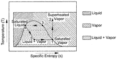
- T-s temperature-entropy
- the low temperature waste heat stream W 1 supplied from the waste heat source is heat-exchanged with the liquid refrigerant stream F 4 through the first heat exchanger 101, and in the diagram of FIG. 3, along a path of 5 ⁇ 1.
- Heat exchange is carried out.
- the heat exchanged gaseous refrigerant stream F 1 is compressed in the compressor 102, in this case compressed along the path 1 ⁇ 2 in the diagram of FIG. 3.
- the high temperature and high pressure refrigerant flow F 2 in the gas state compressed according to the compression process flows into the second heat exchanger 103, and heats the high temperature heat source along the path 2 ⁇ 4 of FIG. 3.
- the high pressure refrigerant flow F 3 in the liquid state deprived of heat is thus expanded through the pressure drop device 104 and in the diagram of FIG. 3 along the path 4 ⁇ 5.
- the heat recovery apparatus 10 and method of the present application can be applied to various petrochemical processes.
- the temperature of the waste heat generated in the process is about 85 ° C.
- the calorific value of about 6.8 Gcal / hr is discarded, it is possible to apply to the cumene manufacturing process.
- the temperature of the waste heat generated in the absorber is about 75 ° C. In this case, the heat amount of about 1.6 to 3.4 Gcal / hr is discarded, and it is applicable to the process of producing acrylic acid.
- the heat recovery apparatus and method of the present application by using the waste heat of the low-grade heat source of sensible heat of 70 °C or more discharged from industrial sites or various chemical processes, for example, the manufacturing process of petrochemical products, 1 It can be produced using only the heat exchanger of the machine, and since the generated steam can be used in various processes, it is possible to reduce the amount of hot steam, which is an external heat source for use in a reactor or a distillation column, to maximize energy saving efficiency. .
- FIG. 1 is a view schematically showing a conventional waste heat treatment apparatus.
- FIG. 2 is a view schematically showing a heat recovery apparatus of an embodiment of the present application.
- 3 is a graph illustrating temperature-entropy by way of the waste heat recovery apparatus and method of the present application.
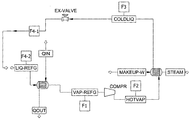
- FIG. 4 is a view showing a heat recovery apparatus according to an embodiment of the present application.
- the refrigerant was circulated at a flow rate of 30,000 kg / hr such that the refrigerant (1,1,1,3,3-pentafluoropropane, R245fa) sequentially passed through the first heat exchanger, the compressor, the second heat exchanger and the control valve.
- a refrigerant flow of 75.4 ° C., 6.2 kgf / cm 2 g (7.1 bar) and a gas volume fraction of 0.0 is introduced into the first heat exchanger, and at the same time, 85.0 ° C. and 1.0 kgf / cm to the first heat exchanger.
- 2 g (2.0 bar) waste heat flow with a gas volume fraction of 0.0 was introduced at a flow rate of 300,000 kg / hr for heat exchange.
- the waste heat flow was flowed at a flow rate of 300,000 kg / hr in a state of 83.3 ° C, 1.0 kgf / cm 2 g, and a gas volume fraction of 0.0, and the refrigerant flow was 80 ° C, 6.2 kgf / cm 2 g (7.1 bar). ), And the gas volume fraction flowed out to 1.0, and then flowed into the first compressor.
- the refrigerant flow compressed in the compressor flowed out of the compressor at a state of 127 ° C, 21.4 kgf / cm 2 g (22.0 bar), and a gas volume fraction of 0.88.
- the amount of work used in the compressor was 220,404 W.
- the refrigerant flow flowing out of the compressor is introduced into a second heat exchanger, and at the same time, the water is heated at 100 ° C., 0.99 kgf / cm 2 g (1.98 bar), and a gas volume fraction of 0.02 kg to the second heat exchanger. It was introduced at a flow rate of to exchange heat with the refrigerant flow. After the heat exchange, the water was discharged to steam at a temperature of 120 ° C., 0.99 kgf / cm 2 g, and a gas volume fraction of 1.0, and the refrigerant flow was condensed to 126 ° C., 21.4 kgf / cm 2 g (22.0 bar), and a gas volume fraction. Flowed into the control valve after being discharged to 0.0.
- the flow of the refrigerant passing through the control valve was flowed out of the control valve with 75.4 ° C., 6.2 kgf / cm 2 g (7.1 bar), and a gas volume fraction of 0.66, and was reflowed into the first heat exchanger.
- the pressure drop device generated 72,874 W of electrical energy using the mechanical energy of the fluid flow.
- the coefficient of performance of the heat recovery device was calculated by the following general formula 4, it is shown in Table 1 below.
- Q represents the amount of heat condensed by the second heat exchanger
- W represents the amount of work done by the compressor
- a refrigerant flow with 75.4 ° C., 6.2 kgf / cm 2 g (7.1 bar) and gas volume fraction 0.0 is introduced into the first heat exchanger, while at the same time 95 ° C., 1.0 kgf / cm 2 g, gas Waste heat flow with a volume fraction of 0.0 was introduced at a flow rate of 300,000 kg / hr for heat exchange. After heat exchange in the first heat exchanger, the refrigerant flow was heated at 90 ° C., 6.2 kgf / cm 2 g (7.1 bar).
- a refrigerant flow of 68.5 ° C., 5.0 kgf / cm 2 g (5.9 bar) and a gas volume fraction of 0.0 is introduced into the first heat exchanger and at the same time 95 ° C., 1.0 kgf / cm 2 g, gas Waste heat flow with a volume fraction of 0.0 was introduced at a flow rate of 300,000 kg / hr for heat exchange. After heat exchange in the first heat exchanger, the refrigerant flow was flowed at 90 ° C., 5.0 kgf / cm 2 g (5.9 bar).
- a refrigerant flow with 79.6 ° C., 7.0 kgf / cm 2 g (7.9 bar), gas volume fraction 0.0 is introduced into the first heat exchanger and at the same time 90 ° C., 1.0 kgf / cm 2 g, gas to the first heat exchanger.
- Waste heat flow with a volume fraction of 0.0 was introduced at a flow rate of 300,000 kg / hr for heat exchange.
- the refrigerant flow was 85 ° C., 7.0 kgf / cm 2 g (7.9 bar) , Flowed into the compressor with a gas volume fraction of 1.0, and the refrigerant flow compressed in the compressor flowed out of the compressor at 108 ° C., 14.2 kgf / cm 2 g (15.0 bar), and with a gas volume fraction of 1.0.
- the second heat exchanger was introduced into a second heat exchanger to exchange heat with water of 80 ° C., and the refrigerant flow exchanged from the second heat exchanger was 107 ° C., 14.2 kgf / cm 2 g (15.0 bar), and gas. Flowed out with a volume fraction of 0.0, Except for producing steam in the same manner as in Example 1, in this case, the coefficient of performance of the heat recovery device and the temperature of the steam is shown in Table 2 below.
- a refrigerant flow with 61.9 ° C., 4.0 kgf / cm 2 g (4.9 bar) and a gas volume fraction of 0.0 is introduced into the first heat exchanger, while at the same time 70 ° C., 1.0 kgf / cm 2 g, gas Waste heat flow with a volume fraction of 0.0 was introduced at a flow rate of 300,000 kg / hr, and heat exchange was performed. After heat exchange in the first heat exchanger, the refrigerant flow was 65 ° C., 4.0 kgf / cm 2 g (4.9 bar).
Abstract
Description
| 실시예 1 | 실시예 2 | 실시예 3 | |||||
| TF(℃) | TR(℃) | 85 | 75.4 | 95 | 75.4 | 95 | 68.5 |
| TF - TR(℃) | 9.6 | 19.6 | 16.5 | ||||
| PC(bar) | PH(bar) | 22 | 7.1 | 24.8 | 7.1 | 24.8 | 5.9 |
| PC/PH | 3.1 | 3.5 | 4.2 | ||||
| Q(W) | 702,874 | 678,737 | 625,323 | ||||
| Total W(W) | 220,404 | 255,159 | 256,294 | ||||
| COP | 3.19 | 2.67 | 2.44 | ||||
| 스팀의 온도(℃) | 120 | 120 | 120 | ||||
| 비교예 1 | 비교예 2 | ||||
| TF(℃) | TR(℃) | 90 | 79.6 | 70 | 61.9 |
| TF - TR(℃) | 10.4 | 8.1 | |||
| PC(bar) | PH(bar) | 15.0 | 7.9 | 25.2 | 4.9 |
| PC/PH | 1.9 | 5.14 | |||
| Q(W) | 38,589 | 510,992 | |||
| Total W(W) | 126,919 | 236,665 | |||
| COP | 0.30 | 2.16 | |||
| 스팀의 온도(℃) | 103 | 120 | |||
Claims (28)
- 냉매가 흐르는 배관을 통하여 유체 연결된 제 1 열교환기, 압축기, 제 2 열교환기 및 압력 강하 장치를 포함하고,상기 제 1 열교환기로 유입되는 냉매 흐름은 상기 제 1 열교환기로 유입되는 70℃ 이상의 유체 흐름과 열교환되며,상기 제 1 열교환기에서 유출되는 냉매 흐름은, 상기 압축기로 유입되고,상기 압축기에서 유출되는 냉매 흐름은 상기 제 2 열교환기로 유입되어 상기 제 2 열교환기로 유입되는 유체 흐름과 열교환되며,상기 제 2 열교환기에서 유출되는 냉매 흐름은 상기 압력 강하 장치로 유입되고,상기 압력 강하 장치에서 유출되는 냉매 흐름은 상기 제 1 열교환기로 재유입되며,상기 제 1 열교환기에서 유출되는 냉매 흐름의 압력과 상기 압축기에서 유출되는 냉매 흐름의 압력의 비가 하기 일반식 1을 만족하는 열 회수 장치:[일반식 1]2 ≤ PC/PH ≤ 5상기 일반식 1에서, PC는 상기 압축기에서 유출되는 냉매 흐름의 압력을 나타내고, PH은 상기 제 1 열교환기에서 유출되는 냉매 흐름의 압력을 나타낸다.
- 제 1 항에 있어서, 제 1 열교환기로 유입되는 유체 흐름은, 폐열 흐름 또는 응축기를 통과한 응축수의 흐름인 열 회수 장치.
- 제 1 항에 있어서, 제 1 열교환기에서 유출되는 냉매 흐름의 온도와 상기 제 1 열교환기로 유입되는 유체 흐름의 온도가 하기 일반식 2를 만족하는 열 회수 장치:[일반식 2]1℃ ≤ TF - TR ≤ 20℃상기 일반식 2에서, TF는 상기 제 1 열교환기로 유입되는 유체 흐름의 온도를 나타내고, TR은 상기 제 1 열교환기에서 유출되는 냉매 흐름의 온도를 나타낸다.
- 제 1 항에 있어서, 냉매의 유량은 5,000 kg/hr 내지 231,000 kg/hr인 열 회수 장치
- 제 1 항에 있어서, 냉매 흐름은, 60℃ 내지 105℃의 온도로 제 1 열교환기로 유입되는 열 회수 장치.
- 제 1 항에 있어서, 제 1 열교환기로 유입되는 유체 흐름의 유량은 50,000 kg/hr 내지 2,300,000 kg/hr인 열 회수 장치.
- 제 1 항에 있어서, 제 1 열교환기에서 유출되는 유체 흐름의 온도는 68℃ 내지 102℃인 열 회수 장치.
- 제 1 항에 있어서, 제 1 열교환기에서 유출되는 냉매 흐름의 온도는 65℃ 내지 105℃인 열 회수 장치.
- 제 1 항에 있어서, 제 1 열교환기에서 유출되는 냉매 흐름의 압력은 3.0 kgf/cm2g 내지 20.0 kgf/cm2g인 열 회수 장치.
- 제 1 항에 있어서, 압축기에서 유출되는 냉매 흐름의 온도는 125℃ 내지 185℃인 열 회수 장치.
- 제 1 항에 있어서, 압축기에서 유출되는 냉매 흐름의 압력은 9.0 kgf/cm2g 내지 62.5 kgf/cm2g인 열 회수 장치.
- 제 1 항에 있어서, 제 2 열교환기로 유입되는 유체 흐름의 유량은 500 kg/hr 내지 10,000 kg/hr인 열 회수 장치
- 제 1 항에 있어서, 제 2 열교환기로 유입되는 유체는 물이며, 상기 제 2 열교환기에서 열교환된 물은 스팀으로 배출되는 열 회수 장치.
- 제 13 항에 있어서, 제 2 열교환기로 유입되는 물의 온도는 70℃ 내지 105℃인 열 회수 장치.
- 제 13 항에 있어서, 스팀의 온도는 120℃ 이상인 열 회수 장치.
- 제 13 항에 있어서, 스팀의 압력은 0.99 kgf/cm2g 내지 10.5 kgf/cm2g인 열 회수 장치.
- 제 13 항에 있어서, 스팀을 압축시키는 하나 이상의 스팀 압축기를 추가로 포함하는 열 회수 장치.
- 제 13 항에 있어서, 스팀을 응축시키는 하나 이상의 스팀 응축기를 추가로 포함하는 열 회수 장치.
- 제 1 항에 있어서, 상기 제 2 열교환기에서 유출되는 냉매 흐름의 온도는 125℃ 내지 190℃의 온도인 열 회수 장치.
- 제 1 항에 있어서, 압력 강하 장치에서 유출되는 냉매 흐름의 온도는 65℃ 내지 105℃인 열 회수 장치.
- 냉매 흐름을 제 1 열교환기로 유입시키고, 상기 제 1 열교환기에서 유출되는 냉매 흐름을 압축기로 유입시키며, 상기 압축기에서 유출되는 냉매 흐름을 제 2 열교환기로 유입시키고, 상기 제 2 열교환기에서 유출되는 냉매 흐름을 압력 강하 장치로 유입시키며, 상기 압력 강하 장치에서 유출되는 냉매 흐름을 상기 제 1 열교환기로 유입시키는 냉매 순환 단계;상기 제 1 열교환기로 유입되는 냉매 흐름을 상기 제 1 열교환기로 유입되는 70℃ 이상의 유체 흐름과 열교환시키는 제 1 열교환 단계;상기 압축기에서 유출되는 냉매 흐름을 상기 제 2 열교환기로 유입되는 유체 흐름과 열교환시키는 제 2 열교환 단계; 및상기 제 1 열교환기에서 유출되는 냉매 흐름의 압력과 상기 압축기에서 유출되는 냉매 흐름의 압력의 비가 하기 일반식 1을 만족하도록 조절하는 압력 조절 단계를 포함하는 열 회수 방법:[일반식 1]2 ≤ PC/PH ≤ 5상기 일반식 1에서, PC는 상기 압축기에서 유출되는 냉매 흐름의 압력을 나타내고, PH은 상기 제 1 열교환기에서 유출되는 냉매 흐름의 압력을 나타낸다.
- 제 21 항에 있어서, 제 1 열교환기로 유입되는 유체 흐름은, 폐열 흐름 또는 응축기를 통과한 응축수의 흐름인 열 회수 방법.
- 제 21 항에 있어서, 제 1 열교환기에서 유출되는 냉매 흐름의 온도와 상기 제 1 열교환기로 유입되는 유체 흐름의 온도가 하기 일반식 2를 만족하도록 조절하는 것을 추가로 포함하는 열 회수 방법:[일반식 2]1℃ ≤ TF - TR ≤ 20℃상기 일반식 2에서, TF는 상기 제 1 열교환기로 유입되는 유체 흐름의 온도를 나타내고, TR은 상기 제 1 열교환기에서 유출되는 냉매 흐름의 온도를 나타낸다.
- 제 21 항에 있어서, 제 2 열교환기로 유입되는 유체는 물이며, 상기 제 2 열교환기에서 열교환된 물은 스팀으로 배출되는 열 회수 방법.
- 제 24 항에 있어서, 스팀의 온도는 120℃ 이상인 열 회수 방법.
- 제 24 항에 있어서, 스팀의 압력은 0.99 kgf/cm2g 내지 10.5 kgf/cm2g인 열 회수 방법.
- 제 24 항에 있어서, 스팀을 압축시키는 단계를 추가로 포함하는 열 회수 방법.
- 제 24 항에 있어서, 스팀을 응축시키는 단계를 추가로 포함하는 열 회수 방법.
Priority Applications (4)
| Application Number | Priority Date | Filing Date | Title |
|---|---|---|---|
| EP14818613.3A EP3015794B1 (en) | 2013-06-24 | 2014-06-20 | Heat recovery method |
| CN201480046964.8A CN105492842A (zh) | 2013-06-24 | 2014-06-20 | 热回收设备 |
| US14/392,187 US9612045B2 (en) | 2013-06-24 | 2014-06-20 | Heat recovery apparatus |
| JP2016521213A JP6213855B2 (ja) | 2013-06-24 | 2014-06-20 | 熱回収装置 |
Applications Claiming Priority (4)
| Application Number | Priority Date | Filing Date | Title |
|---|---|---|---|
| KR20130072552 | 2013-06-24 | ||
| KR10-2013-0072552 | 2013-06-24 | ||
| KR10-2014-0075678 | 2014-06-20 | ||
| KR1020140075678A KR101995728B1 (ko) | 2013-06-24 | 2014-06-20 | 열 회수 장치 |
Publications (1)
| Publication Number | Publication Date |
|---|---|
| WO2014208938A1 true WO2014208938A1 (ko) | 2014-12-31 |
Family
ID=52474541
Family Applications (1)
| Application Number | Title | Priority Date | Filing Date |
|---|---|---|---|
| PCT/KR2014/005474 WO2014208938A1 (ko) | 2013-06-24 | 2014-06-20 | 열 회수 장치 |
Country Status (6)
| Country | Link |
|---|---|
| US (1) | US9612045B2 (ko) |
| EP (1) | EP3015794B1 (ko) |
| JP (1) | JP6213855B2 (ko) |
| KR (1) | KR101995728B1 (ko) |
| CN (1) | CN105492842A (ko) |
| WO (1) | WO2014208938A1 (ko) |
Cited By (3)
| Publication number | Priority date | Publication date | Assignee | Title |
|---|---|---|---|---|
| JP2016200314A (ja) * | 2015-04-08 | 2016-12-01 | 富士電機株式会社 | ヒートポンプ式蒸気生成装置及びヒートポンプ式蒸気生成装置の運転方法 |
| JP2018513956A (ja) * | 2015-06-18 | 2018-05-31 | エルジー・ケム・リミテッド | 熱回収装置 |
| JP2018528075A (ja) * | 2016-06-16 | 2018-09-27 | エルジー・ケム・リミテッド | 溶媒分離装置および廃熱活用方法 |
Families Citing this family (3)
| Publication number | Priority date | Publication date | Assignee | Title |
|---|---|---|---|---|
| KR102166467B1 (ko) * | 2016-10-05 | 2020-10-16 | 주식회사 엘지화학 | 용매 분리 장치 및 용매 분리 방법 |
| KR101878234B1 (ko) * | 2016-12-05 | 2018-07-16 | 한국에너지기술연구원 | 고온증기 생산을 위한 증기 주입 히트펌프 시스템 |
| DE102018114762B4 (de) * | 2017-07-10 | 2023-12-28 | Hanon Systems | Verfahren zum Betreiben einer Klimaanlage eines Kraftfahrzeuges |
Citations (5)
| Publication number | Priority date | Publication date | Assignee | Title |
|---|---|---|---|---|
| US4226606A (en) * | 1978-10-06 | 1980-10-07 | Air & Refrigeration Corp. | Waste heat recovery system |
| KR100443815B1 (ko) * | 2001-12-24 | 2004-08-09 | 주식회사 세기센추리 | 폐열회수 열펌프 유닛 |
| KR20050081866A (ko) * | 2004-02-16 | 2005-08-19 | 태봉산업기술주식회사 | 폐열회수 시스템 |
| JP2007231866A (ja) * | 2006-03-02 | 2007-09-13 | Fujita Corp | 廃熱利用システム |
| US20120023982A1 (en) * | 2009-04-01 | 2012-02-02 | Linum Systems Ltd. | Waste heat air conditioning system |
Family Cites Families (24)
| Publication number | Priority date | Publication date | Assignee | Title |
|---|---|---|---|---|
| US4445461A (en) * | 1982-06-14 | 1984-05-01 | Allis-Chalmers Corporation | Waste heat recovery method and apparatus |
| JPS61125547A (ja) * | 1984-11-21 | 1986-06-13 | 株式会社東芝 | ヒ−トポンプ式ボイラ装置 |
| US5186013A (en) * | 1989-02-10 | 1993-02-16 | Thomas Durso | Refrigerant power unit and method for refrigeration |
| JPH05223204A (ja) * | 1991-12-13 | 1993-08-31 | Nishiyodo Kuuchiyouki Kk | ヒートポンプ利用の蒸気生成方法 |
| JP2001207960A (ja) * | 2000-01-25 | 2001-08-03 | Toyota Autom Loom Works Ltd | 空気調和装置 |
| CN1140749C (zh) * | 2001-10-31 | 2004-03-03 | 清华大学 | 回收燃气、燃油锅炉烟气潜热的电动热泵采暖装置 |
| JP4972421B2 (ja) * | 2006-02-01 | 2012-07-11 | 関西電力株式会社 | ヒートポンプ式蒸気・温水発生装置 |
| JP4555784B2 (ja) * | 2006-02-02 | 2010-10-06 | 株式会社日立製作所 | 低温廃熱を利用した水蒸気発生装置、その装置を用いた熱電供給装置、及び水蒸気発生方法 |
| US20080302113A1 (en) * | 2007-06-08 | 2008-12-11 | Jian-Min Yin | Refrigeration system having heat pump and multiple modes of operation |
| CN201059819Y (zh) * | 2007-07-12 | 2008-05-14 | 北京开源铭典技术有限公司 | 汽轮机驱动开启式热泵装置 |
| JP2010038391A (ja) * | 2008-07-31 | 2010-02-18 | Toyo Eng Works Ltd | ヒートポンプ式蒸気発生装置 |
| CN201255500Y (zh) | 2008-08-11 | 2009-06-10 | 南京工业大学 | 生活浊水余热回收热泵热水器 |
| JP5486174B2 (ja) * | 2008-08-28 | 2014-05-07 | 株式会社前川製作所 | ヒートポンプ装置及び冷媒用往復動型圧縮機 |
| JP5274184B2 (ja) * | 2008-09-30 | 2013-08-28 | 三洋電機株式会社 | ヒートポンプ式乾燥機 |
| JP5605991B2 (ja) * | 2009-01-14 | 2014-10-15 | 株式会社神戸製鋼所 | 蒸気発生装置 |
| JP2010164258A (ja) * | 2009-01-16 | 2010-07-29 | Kobe Steel Ltd | 蒸気発生装置 |
| JP5482519B2 (ja) * | 2010-05-14 | 2014-05-07 | 三浦工業株式会社 | 蒸気システム |
| JP5742079B2 (ja) * | 2010-07-08 | 2015-07-01 | 三浦工業株式会社 | 蒸気システム |
| JP5691557B2 (ja) * | 2011-01-25 | 2015-04-01 | 株式会社Ihi | 蒸気発生方法及び蒸気発生装置 |
| KR101059880B1 (ko) * | 2011-03-09 | 2011-08-29 | 엘지전자 주식회사 | 스크롤 압축기 |
| CN102226604A (zh) * | 2011-06-01 | 2011-10-26 | 西安交通大学 | 一种利用低品位余热产生蒸汽的高温蒸汽热泵系统 |
| JP2013108720A (ja) * | 2011-11-24 | 2013-06-06 | Panasonic Corp | 冷凍サイクル装置およびそれを備えた温水生成装置 |
| JP2013124846A (ja) * | 2011-12-16 | 2013-06-24 | Kansai Electric Power Co Inc:The | ヒートポンプシステム |
| JP5560515B2 (ja) * | 2012-03-31 | 2014-07-30 | 株式会社東洋製作所 | 蒸気製造システム、および蒸気製造システムの立ち上げ制御方法 |
-
2014
- 2014-06-20 WO PCT/KR2014/005474 patent/WO2014208938A1/ko active Application Filing
- 2014-06-20 JP JP2016521213A patent/JP6213855B2/ja active Active
- 2014-06-20 KR KR1020140075678A patent/KR101995728B1/ko active IP Right Grant
- 2014-06-20 CN CN201480046964.8A patent/CN105492842A/zh active Pending
- 2014-06-20 EP EP14818613.3A patent/EP3015794B1/en active Active
- 2014-06-20 US US14/392,187 patent/US9612045B2/en active Active
Patent Citations (5)
| Publication number | Priority date | Publication date | Assignee | Title |
|---|---|---|---|---|
| US4226606A (en) * | 1978-10-06 | 1980-10-07 | Air & Refrigeration Corp. | Waste heat recovery system |
| KR100443815B1 (ko) * | 2001-12-24 | 2004-08-09 | 주식회사 세기센추리 | 폐열회수 열펌프 유닛 |
| KR20050081866A (ko) * | 2004-02-16 | 2005-08-19 | 태봉산업기술주식회사 | 폐열회수 시스템 |
| JP2007231866A (ja) * | 2006-03-02 | 2007-09-13 | Fujita Corp | 廃熱利用システム |
| US20120023982A1 (en) * | 2009-04-01 | 2012-02-02 | Linum Systems Ltd. | Waste heat air conditioning system |
Cited By (4)
| Publication number | Priority date | Publication date | Assignee | Title |
|---|---|---|---|---|
| JP2016200314A (ja) * | 2015-04-08 | 2016-12-01 | 富士電機株式会社 | ヒートポンプ式蒸気生成装置及びヒートポンプ式蒸気生成装置の運転方法 |
| JP2018513956A (ja) * | 2015-06-18 | 2018-05-31 | エルジー・ケム・リミテッド | 熱回収装置 |
| US10591219B2 (en) | 2015-06-18 | 2020-03-17 | Lg Chem, Ltd. | Heat recovery apparatus |
| JP2018528075A (ja) * | 2016-06-16 | 2018-09-27 | エルジー・ケム・リミテッド | 溶媒分離装置および廃熱活用方法 |
Also Published As
| Publication number | Publication date |
|---|---|
| EP3015794A4 (en) | 2017-04-19 |
| JP2016522388A (ja) | 2016-07-28 |
| CN105492842A (zh) | 2016-04-13 |
| KR101995728B1 (ko) | 2019-07-03 |
| KR20150000422A (ko) | 2015-01-02 |
| US20160187036A1 (en) | 2016-06-30 |
| JP6213855B2 (ja) | 2017-10-18 |
| EP3015794B1 (en) | 2020-11-04 |
| EP3015794A1 (en) | 2016-05-04 |
| US9612045B2 (en) | 2017-04-04 |
Similar Documents
| Publication | Publication Date | Title |
|---|---|---|
| WO2014208938A1 (ko) | 열 회수 장치 | |
| US6701712B2 (en) | Method of and apparatus for producing power | |
| US20120047889A1 (en) | Energy Conversion Using Rankine Cycle System | |
| JP5542958B2 (ja) | 廃熱回収システム | |
| US20140000261A1 (en) | Triple expansion waste heat recovery system and method | |
| WO2012065296A1 (zh) | 吸收式冷功联供循环系统和吸收式冷功联供方法 | |
| JP2005527808A (ja) | 少なくとも1つの高温原子炉のコアで生成される熱から電気を生成する方法及び装置 | |
| WO2015058485A1 (zh) | 一种温差发电方法和系统 | |
| CN103161528A (zh) | 回收工质有效成分制冷的功冷联产系统及方法 | |
| CN104501275A (zh) | 充分利用电厂余热的梯级加热供热系统 | |
| WO2017217585A1 (ko) | 직접 연소 타입의 초임계 이산화탄소 발전 시스템 | |
| CN110388832A (zh) | 一种利用导热油回收工业废气余热的系统 | |
| CN106839790B (zh) | 一种电转炉烟气余热发电系统 | |
| CN210400027U (zh) | 一种利用导热油回收工业废气余热的系统 | |
| WO2015050372A1 (ko) | 복합열원을 이용한 발전 시스템 | |
| KR101999811B1 (ko) | 초임계 랭킨 사이클 기반의 열기관 및 이 열기관의 동작방법 | |
| WO2016108578A1 (ko) | 증발장치에 의한 고효율 저온 발전시스템 | |
| CN105422457A (zh) | 无油螺杆空压机热回收梯级利用系统及控制方法 | |
| CN211082000U (zh) | 一种有机朗肯与逆卡诺循环耦合的余热回收系统 | |
| CN205638584U (zh) | 一种低温热回收相关的能量集成系统 | |
| JPS633088A (ja) | コ−クス炉の排熱回収方法 | |
| WO2014098508A1 (ko) | 열기관과 열펌프가 조합하여 동력을 얻는 시스템 | |
| CN210264841U (zh) | 一种带旁通阀的余热发电系统 | |
| JP3230554U (ja) | ボイラ蒸気供給能力を向上させる酸素除去器連合冷再熱循環システム | |
| JP3230555U (ja) | ボイラ冷再熱蒸気供給能力を向上させる酸素除去器連合利用システム |
Legal Events
| Date | Code | Title | Description |
|---|---|---|---|
| WWE | Wipo information: entry into national phase |
Ref document number: 201480046964.8 Country of ref document: CN |
|
| 121 | Ep: the epo has been informed by wipo that ep was designated in this application |
Ref document number: 14818613 Country of ref document: EP Kind code of ref document: A1 |
|
| WWE | Wipo information: entry into national phase |
Ref document number: 2014818613 Country of ref document: EP |
|
| ENP | Entry into the national phase |
Ref document number: 2016521213 Country of ref document: JP Kind code of ref document: A |
|
| WWE | Wipo information: entry into national phase |
Ref document number: 14392187 Country of ref document: US |
|
| NENP | Non-entry into the national phase |
Ref country code: DE |