WO2014208752A1 - 光レセプタクル - Google Patents
光レセプタクル Download PDFInfo
- Publication number
- WO2014208752A1 WO2014208752A1 PCT/JP2014/067264 JP2014067264W WO2014208752A1 WO 2014208752 A1 WO2014208752 A1 WO 2014208752A1 JP 2014067264 W JP2014067264 W JP 2014067264W WO 2014208752 A1 WO2014208752 A1 WO 2014208752A1
- Authority
- WO
- WIPO (PCT)
- Prior art keywords
- ferrule
- optical fiber
- diameter portion
- optical
- elastic member
- Prior art date
- Legal status (The legal status is an assumption and is not a legal conclusion. Google has not performed a legal analysis and makes no representation as to the accuracy of the status listed.)
- Ceased
Links
Images






Classifications
-
- G—PHYSICS
- G02—OPTICS
- G02B—OPTICAL ELEMENTS, SYSTEMS OR APPARATUS
- G02B6/00—Light guides; Structural details of arrangements comprising light guides and other optical elements, e.g. couplings
- G02B6/24—Coupling light guides
- G02B6/36—Mechanical coupling means
- G02B6/38—Mechanical coupling means having fibre to fibre mating means
- G02B6/3807—Dismountable connectors, i.e. comprising plugs
- G02B6/3833—Details of mounting fibres in ferrules; Assembly methods; Manufacture
- G02B6/3855—Details of mounting fibres in ferrules; Assembly methods; Manufacture characterised by the method of anchoring or fixing the fibre within the ferrule
-
- G—PHYSICS
- G02—OPTICS
- G02B—OPTICAL ELEMENTS, SYSTEMS OR APPARATUS
- G02B6/00—Light guides; Structural details of arrangements comprising light guides and other optical elements, e.g. couplings
- G02B6/24—Coupling light guides
- G02B6/42—Coupling light guides with opto-electronic elements
- G02B6/4292—Coupling light guides with opto-electronic elements the light guide being disconnectable from the opto-electronic element, e.g. mutually self aligning arrangements
-
- G—PHYSICS
- G02—OPTICS
- G02B—OPTICAL ELEMENTS, SYSTEMS OR APPARATUS
- G02B6/00—Light guides; Structural details of arrangements comprising light guides and other optical elements, e.g. couplings
- G02B6/24—Coupling light guides
- G02B6/36—Mechanical coupling means
- G02B6/38—Mechanical coupling means having fibre to fibre mating means
- G02B6/3807—Dismountable connectors, i.e. comprising plugs
- G02B6/381—Dismountable connectors, i.e. comprising plugs of the ferrule type, e.g. fibre ends embedded in ferrules, connecting a pair of fibres
- G02B6/3818—Dismountable connectors, i.e. comprising plugs of the ferrule type, e.g. fibre ends embedded in ferrules, connecting a pair of fibres of a low-reflection-loss type
- G02B6/382—Dismountable connectors, i.e. comprising plugs of the ferrule type, e.g. fibre ends embedded in ferrules, connecting a pair of fibres of a low-reflection-loss type with index-matching medium between light guides
-
- G—PHYSICS
- G02—OPTICS
- G02B—OPTICAL ELEMENTS, SYSTEMS OR APPARATUS
- G02B6/00—Light guides; Structural details of arrangements comprising light guides and other optical elements, e.g. couplings
- G02B6/24—Coupling light guides
- G02B6/36—Mechanical coupling means
- G02B6/38—Mechanical coupling means having fibre to fibre mating means
- G02B6/3807—Dismountable connectors, i.e. comprising plugs
- G02B6/3833—Details of mounting fibres in ferrules; Assembly methods; Manufacture
- G02B6/3834—Means for centering or aligning the light guide within the ferrule
-
- G—PHYSICS
- G02—OPTICS
- G02B—OPTICAL ELEMENTS, SYSTEMS OR APPARATUS
- G02B6/00—Light guides; Structural details of arrangements comprising light guides and other optical elements, e.g. couplings
- G02B6/24—Coupling light guides
- G02B6/36—Mechanical coupling means
- G02B6/38—Mechanical coupling means having fibre to fibre mating means
- G02B6/3807—Dismountable connectors, i.e. comprising plugs
- G02B6/3833—Details of mounting fibres in ferrules; Assembly methods; Manufacture
- G02B6/3834—Means for centering or aligning the light guide within the ferrule
- G02B6/3843—Means for centering or aligning the light guide within the ferrule with auxiliary facilities for movably aligning or adjusting the fibre within its ferrule, e.g. measuring position or eccentricity
-
- G—PHYSICS
- G02—OPTICS
- G02B—OPTICAL ELEMENTS, SYSTEMS OR APPARATUS
- G02B6/00—Light guides; Structural details of arrangements comprising light guides and other optical elements, e.g. couplings
- G02B6/24—Coupling light guides
- G02B6/36—Mechanical coupling means
- G02B6/38—Mechanical coupling means having fibre to fibre mating means
- G02B6/3807—Dismountable connectors, i.e. comprising plugs
- G02B6/3833—Details of mounting fibres in ferrules; Assembly methods; Manufacture
- G02B6/3846—Details of mounting fibres in ferrules; Assembly methods; Manufacture with fibre stubs
-
- G—PHYSICS
- G02—OPTICS
- G02B—OPTICAL ELEMENTS, SYSTEMS OR APPARATUS
- G02B6/00—Light guides; Structural details of arrangements comprising light guides and other optical elements, e.g. couplings
- G02B6/24—Coupling light guides
- G02B6/36—Mechanical coupling means
- G02B6/38—Mechanical coupling means having fibre to fibre mating means
- G02B6/3807—Dismountable connectors, i.e. comprising plugs
- G02B6/3833—Details of mounting fibres in ferrules; Assembly methods; Manufacture
- G02B6/3855—Details of mounting fibres in ferrules; Assembly methods; Manufacture characterised by the method of anchoring or fixing the fibre within the ferrule
- G02B6/3861—Adhesive bonding
-
- G—PHYSICS
- G02—OPTICS
- G02B—OPTICAL ELEMENTS, SYSTEMS OR APPARATUS
- G02B6/00—Light guides; Structural details of arrangements comprising light guides and other optical elements, e.g. couplings
- G02B6/24—Coupling light guides
- G02B6/36—Mechanical coupling means
- G02B6/38—Mechanical coupling means having fibre to fibre mating means
- G02B6/3807—Dismountable connectors, i.e. comprising plugs
- G02B6/3833—Details of mounting fibres in ferrules; Assembly methods; Manufacture
- G02B6/3863—Details of mounting fibres in ferrules; Assembly methods; Manufacture fabricated by using polishing techniques
-
- G—PHYSICS
- G02—OPTICS
- G02B—OPTICAL ELEMENTS, SYSTEMS OR APPARATUS
- G02B6/00—Light guides; Structural details of arrangements comprising light guides and other optical elements, e.g. couplings
- G02B6/24—Coupling light guides
- G02B6/42—Coupling light guides with opto-electronic elements
- G02B6/4201—Packages, e.g. shape, construction, internal or external details
- G02B6/4204—Packages, e.g. shape, construction, internal or external details the coupling comprising intermediate optical elements, e.g. lenses, holograms
- G02B6/421—Packages, e.g. shape, construction, internal or external details the coupling comprising intermediate optical elements, e.g. lenses, holograms the intermediate optical component consisting of a short length of fibre, e.g. fibre stub
Definitions
- An aspect of the present invention generally relates to an optical receptacle related to an optical transceiver module for optical communication.
- An optical receptacle is used as a component for optically connecting an optical fiber connector to an optical element such as a light receiving element or a light emitting element in an optical module of an optical communication transceiver (for example, see Patent Document 1).
- optical communication transceivers are required to increase in speed.
- the shape of a transceiver or the like that adopts a receptacle-type optical module is standardized. If the modulation speed of an optical signal emitted from a semiconductor laser, which is one of optical elements, is increased, the space required for an electric circuit is increased. Since the size of the optical module increases, there is a demand for downsizing the optical module.
- an optical receptacle for miniaturizing an optical module there is known a method of providing a cylindrical recess in a part of a ferrule as in Patent Document 2 and providing a lateral groove having a predetermined width on the optical element side. Yes.
- a method of providing a cylindrical recess in a part of a ferrule as in Patent Document 2 and providing a lateral groove having a predetermined width on the optical element side Yes.
- the optical fiber protrudes from the through hole of the ferrule, and when the external force is applied to the optical fiber,
- the module is used as a module, there is a problem that the coupling efficiency is lowered due to the movement of the protruding portion of the optical fiber.
- An aspect of the present invention has been made to solve the above-described problem.
- an optical receptacle is miniaturized, the optical fiber is prevented from being bent or cracked due to an external force or a temperature change, and economical production is achieved.
- An object of the present invention is to provide an optical receptacle that can be used.
- an optical fiber having a core and a cladding for conducting light, a ferrule having a through hole to which the optical fiber is fixed, and the through hole of the ferrule are filled together with the optical fiber.
- a retainer for holding the fiber stub, and the through hole of the ferrule has a small diameter portion in which the optical fiber is disposed, and a side optically connected to the plug ferrule
- the elastic member includes the core and In the end face of the fiber stub that has substantially the same refractive index, is filled in the large-diameter portion together with the small-diameter portion, and is opposite to the side optically connected to the plug ferrule,
- Optical receptacle at least part of the serial elastic member is characterized in that it is polished so as to plane portion
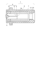
- FIG. 1 is a schematic cross-sectional view of an optical receptacle showing a first embodiment of the present invention.
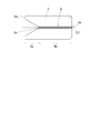
- FIG. 2 is a schematic cross-sectional view of the fiber stub in the first embodiment of the present invention.
- FIG. 3 is a schematic cross-sectional view of an optical receptacle showing a second embodiment of the present invention.
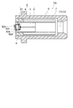
- FIG. 4A and FIG. 4B are schematic cross-sectional views of an optical receptacle showing a third embodiment of the present invention.
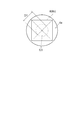
- FIG. 5 is a schematic plan view showing a large-diameter portion when viewed in the direction of the arrow A1 shown in FIG.
- FIG. 6 is a schematic cross-sectional view of an optical receptacle showing a fourth embodiment of the present invention.
- FIG. 1 is a schematic cross-sectional view of an optical receptacle showing a first embodiment of the present invention.
- FIG. 2 is a schematic cross-sectional view of the fiber stub in the first embodiment of the
- FIG. 7 is a schematic cross-sectional view of an optical receptacle showing a fifth embodiment of the present invention.
- FIG. 8 is a schematic cross-sectional view of an optical receptacle showing a sixth embodiment of the present invention.
- FIG. 9A and FIG. 9B are schematic views of an optical receptacle showing a seventh embodiment of the present invention.
- FIG. 10A and FIG. 10B are schematic perspective views showing the fiber stub of the present embodiment.
- the first invention includes an optical fiber having a core and a clad for conducting light, a ferrule having a through-hole to which the optical fiber is fixed, and an elastic member filled in the through-hole of the ferrule together with the optical fiber And a holding tool for holding the fiber stub, and the through hole of the ferrule has a small diameter portion where the optical fiber is disposed, and a side opposite to the side optically connected to the plug ferrule.
- the optical fiber is disposed in the small diameter portion in the through hole of the ferrule over the entire area, and the elastic member is substantially the same as the core.
- the elastic portion has a refractive index, is filled in the large diameter portion together with the small diameter portion At least a portion of an optical receptacle, characterized in that it is polished so as to plane portion.
- the optical fiber is arranged in the small diameter portion of the through-hole of the ferrule over the entire area, so that a large external force is not directly applied to the optical fiber, and the optical fiber is bent or cracked and coupled. A decrease in efficiency can be prevented. Furthermore, while making the refractive index of the elastic member filled in the through hole of the ferrule substantially equal to the core of the optical fiber, the end surface opposite to the end surface to which the plug ferrule and the fiber stub are connected is a flat surface. Even if the end face of the optical fiber is not processed, it is possible to prevent a reduction in coupling efficiency due to reflection and to achieve economical production.
- the flat portion of the elastic member protrudes from the end surface of the ferrule on the end surface of the fiber stub opposite to the side optically connected to the plug ferrule.
- the elastic member is usually softer than ceramics generally used as a ferrule material or quartz glass used as an optical fiber material, and thus can easily form a flat surface. It was possible to produce economically.
- 3rd invention is a fiber stub, Comprising: The optical fiber which has a core which conducts light, The ferrule which has a through-hole which fixes the said optical fiber, The translucent member fixed to the said ferrule, The said light A fiber stub having an optical member for fixing a fiber to the ferrule and fixing the translucent member to the ferrule, and a holder for holding the fiber stub, and the through hole has a small diameter portion, A large-diameter portion having a diameter larger than the small-diameter portion provided on a side opposite to the side where the fiber stub is optically connected to the plug ferrule as viewed from the small-diameter portion, and the entire optical fiber has the small-diameter And the elastic member is filled between the optical fiber and the translucent member.
- optical receptacle since the entire optical fiber is disposed in the small diameter portion of the through hole of the ferrule, it is possible to prevent a large external force from being directly applied to the optical fiber, and the optical fiber is bent or cracked. Can be prevented. Moreover, since the elastic member is filled between the optical fiber and the translucent member, it is possible to prevent a decrease in coupling efficiency due to light reflection at the interface between the optical fiber and the translucent member. In addition, economical production is possible by eliminating the need to polish the end face of the optical fiber.
- the fourth invention is the optical receptacle according to the third invention, wherein the refractive index of the elastic member is substantially the same as the refractive index of the core.
- reflection of light at the interface between the elastic member and the core of the optical fiber can be suppressed, and a decrease in coupling efficiency can be prevented.
- the fifth invention is the optical receptacle according to the third invention, wherein the refractive index of the translucent member is substantially the same as the refractive index of the core.
- this optical receptacle it is possible to suppress the reflection of light at the interface between the translucent member and the core of the optical fiber and between the translucent member and the elastic member, thereby preventing a decrease in coupling efficiency. it can.
- the first end face of the translucent member the first end face provided on a side opposite to a side where the fiber stub is optically connected to the plug ferrule
- At least a part of the optical receptacle is a light receptacle characterized by having a flat surface.
- this optical receptacle it is possible to suppress the reflection of light at the first end face of the translucent member and prevent the coupling efficiency from being lowered.
- a seventh invention is the optical receptacle according to the sixth invention, wherein the plane is inclined at a predetermined angle with respect to a plane perpendicular to a central axis of the ferrule.
- the light reflected from the first end face of the translucent member is prevented from returning to the light emitting element, whereby the light emitting element can be stably operated.
- An eighth invention is the sixth invention, wherein the first end surface is a second end surface of the ferrule, and the fiber stub is provided on a side opposite to a side optically connected to the plug ferrule.
- 2 is an optical receptacle characterized in that it protrudes outside the large-diameter portion from the end face of 2.
- the flat surface when a part of the end surface of the translucent member is formed into a flat surface, the flat surface can be easily formed by polishing or the like because the end surface protrudes from the end surface of the ferrule.
- the ninth invention is the optical receptacle according to the third invention, wherein the central axis of the large diameter portion is inclined at a constant angle with respect to the central axis of the ferrule.
- this optical receptacle by arranging the translucent member at the large diameter portion of the ferrule, it becomes possible to determine the direction in which light is reflected at the end face of the translucent member with high accuracy. It is possible to prevent light reflected from the end face of the translucent member from returning to the light emitting element, and to stably operate the light emitting element.
- a tenth aspect of the invention is the optical receptacle according to the third aspect of the invention, wherein the large diameter portion includes a slit having a certain width passing through the central axis of the ferrule.
- the large diameter portion of the through hole of the ferrule can be easily formed.
- the tilt direction of the bottom surface of the large diameter portion can be easily seen, so the optical module is assembled with high accuracy. be able to.
- FIG. 1 is a schematic cross-sectional view of an optical receptacle showing a first embodiment of the present invention.
- the optical receptacle 1 is a fiber comprising an optical fiber 2 for conducting light, a ferrule 3 having a through hole 3b to which the optical fiber 2 is fixed, and an elastic member 4 filled in the through hole 3b of the ferrule 3 together with the optical fiber 2.
- the optical fiber 2 includes a stub 5, a holder 6 that holds the fiber stub 5, and a sleeve 7 that holds the tip of the fiber stub 5 at one end and can hold the plug ferrule inserted into the optical receptacle 1 at the other end.
- FIG. 2 is a schematic cross-sectional view of a fiber stub showing the first embodiment of the present invention.
- the through hole 3b of the ferrule 3 fills the elastic member 4 on the side opposite to the side that is optically connected to the plug ferrule and the small diameter portion 4b for fixing the optical fiber 2 on the side that is optically connected to the plug ferrule.
- the optical fiber 2 is disposed in the small diameter portion 4b of the ferrule 3 over the entire area.
- the gap between the optical fiber 2 and the through hole 3b of the ferrule 3 and the large diameter portion 4a of the ferrule 3 are filled with an elastic member 4, and the side of the optical fiber 2 opposite to the side that is optically connected to the plug ferrule.
- the end face 2a and the elastic member 4 are in close contact. Note that the elastic member 4 is not shown here for easy understanding of the instruction unit.
- Suitable materials for the ferrule 3 include ceramics and glass.
- zirconia ceramics is used, and the optical fiber 2 is bonded and fixed to the through hole 3b at the center, and one end where the plug ferrule is optically connected is provided.
- a convex spherical surface was formed by polishing.
- the fiber stub 5 is press-fitted and fixed to the holder 6.
- the material suitable for the sleeve 7 includes resin, metal, ceramics, etc., but in this embodiment, a split sleeve made of zirconia ceramics having a slit in the full length direction is used.
- the sleeve 7 holds the tip end polished on the convex spherical surface of the fiber stub 5 at one end, and holds the plug ferrule to be inserted into the optical receptacle 1 at the other end.
- the through-hole 3b of the ferrule 3 gradually moves toward the end surface 3a opposite to the side optically connected to the plug ferrule of the fiber stub 5 (ferrule 3) even if the large diameter portion 4a is cylindrical.
- the diameter may be increased.
- FIG. 1 and FIG. 2 it was set as the shape which expands gradually toward the end surface 3a.
- the diameter of the maximum diameter portion is preferably ⁇ 0.6 mm or more.
- the optical fiber 2 is bonded and fixed to the small diameter portion 4b of the through hole 3b of the ferrule 3 over the entire area.
- the small diameter portion 4 b referred to here is a portion having an inner diameter such that the inner diameter of the through hole 3 b of the ferrule 3 is not more than twice the outer diameter of the optical fiber 2.
- the end surface 2 a of the optical fiber 2 opposite to the side optically connected to the plug ferrule can be a plane that is substantially perpendicular to the central axis C 1 of the optical receptacle 1.
- substantially perpendicular refers to an angle of 85 to 95 degrees with respect to the central axis C 1 of the optical receptacle 1. According to this, the coupling efficiency can be further improved.
- the elastic member 4 is filled without any gap. Thereby, the bias of the elastic member 4 filled around the optical fiber 2 is reduced, and when the optical receptacle 1 is exposed to a temperature change, the difference in the thermal expansion coefficient between the elastic member 4 and the optical fiber 2 causes Breakage and cracking can be prevented. Furthermore, since the amount of fluctuation in the diameter direction in the through hole 3b of the ferrule 3 on the optical fiber end face 2a is reduced, the time required for aligning the light emitting element or the light receiving element with the optical fiber end face 2a is reduced.
- the elastic member 4 may be different in the small diameter portion 4b and the large diameter portion 4a.
- an elastic member 4 having permeability is filled in the through-hole 3b of the ferrule 3.
- the elastic member 4 has a refractive index close to that of the core of the optical fiber 2.
- the near refractive index mentioned here is preferably about 1.4 to 1.6.
- the elastic member 4 can be the same as that for fixing the optical fiber 2 to the through hole 3 b of the ferrule 3.
- the elastic member 4 has a lower elastic modulus than ceramics used as the material for the ferrule 3 and quartz glass used as the material for the optical fiber 2.
- a lower elastic modulus than ceramics used as the material for the ferrule 3 and quartz glass used as the material for the optical fiber 2.
- an epoxy resin, an acrylic resin, a silicon resin, etc. are illustrated.
- the elastic member 4 is in close contact with the end face 2a opposite to the side optically connected to the plug ferrule of the optical fiber 2 without a gap. As a result, reflection of light incident on or emitted from the optical fiber 2 at the boundary surface between the end surface 2a of the optical fiber 2 and the elastic member 4 can be reduced. Coupling efficiency can be improved.
- the end surface 2a of the optical fiber 2 is Since it is not necessary to polish the surface, it can be produced efficiently and economically.
- the end face of the elastic member 4 on the end face 3a side of the ferrule 3 is polished so as to be substantially perpendicular to the central axis C2 of the ferrule 3 or a plane having a certain angle with respect to the central axis C2 of the ferrule 3. Yes.
- the term “substantially perpendicular” here is preferably about 85 to 95 degrees with respect to the central axis C2 of the ferrule 3.
- the fixed angle is, for example, 4 degrees to 10 degrees when viewed from an angle of 90 degrees with respect to the central axis C2 of the ferrule 3.
- the end faces of the optical fiber 2 and the ferrule 3 are arranged on substantially the same plane in order to reduce the above-mentioned reflection, and both are polished simultaneously to form a plane on the end face 2a of the optical fiber 2.
- the elastic member 4 is usually softer than the optical fiber 2 and the ferrule 3, it is possible to form a flat surface more easily than in the past, and to produce efficiently and economically. Can do.
- a method for forming a flat surface on the end face of the elastic member 4 there is a method using a polishing film having diamond abrasive grains. Further, it is desirable that the surface roughness of the plane is an arithmetic average roughness of 0.1 micrometers or less in order to minimize the amount of reflected light.
- FIG. 3 is a schematic cross-sectional view of an optical receptacle showing a second embodiment of the present invention.
- the members constituting the optical receptacle 1 are the same as those in the first embodiment, and the end surface of the elastic member 4 is more than the end surface of the ferrule 3 on the side opposite to the end surface optically connected to the plug ferrule of the fiber stub 5. It sticks out.
- the end surfaces of the optical fiber 2 and the ferrule 3 are arranged on the same plane and polished simultaneously.
- the flat surface is formed on the side of the elastic member 4 opposite to the end face where the fiber stub 5 is optically connected to the plug ferrule, only the elastic member 4 needs to be polished. Since the elastic member 4 is usually softer than the optical fiber 2 and the ferrule 3, it can be easily polished, and a plane can be formed efficiently and economically.
- FIG. 4 is a schematic cross-sectional view of an optical receptacle showing a third embodiment of the present invention.
- FIG. 5 is a schematic plan view showing a large-diameter portion when viewed in the direction of the arrow A1 shown in FIG.
- FIG. 4A is a schematic cross-sectional view showing the optical receptacle according to the present embodiment.
- FIG. 4B is a schematic cross-sectional view showing the fiber stub of the present embodiment.
- An optical receptacle 10 shown in FIG. 4A includes a fiber stub 5, a holder 6, and a sleeve 7.
- the fiber stub 5 includes an optical fiber 2, a translucent member 8, a ferrule 3, and an elastic member 4.
- the optical fiber 2 has a core and a cladding, and conducts light.
- the translucent member 8 transmits light.
- the ferrule 3 has a through hole 3b for fixing the optical fiber 2 and the translucent member 8.
- the elastic member 4 is filled between the optical fiber 2 and the translucent member 8.
- the holder 6 holds the fiber stub 5.
- the sleeve 7 can hold the tip of the fiber stub 5 at one end and the plug ferrule inserted into the optical receptacle 10 at the other end.
- the optical fiber 2 and the translucent member 8 are bonded and fixed in the through hole 3 b of the ferrule 3 using the elastic member 4. Note that the plug ferrule to be inserted into the optical receptacle 10 is not
- the through hole 3b of the ferrule 3 has a small diameter portion 4b for fixing the optical fiber 2 on the side optically connected to the plug ferrule and a side optically connected to the plug ferrule.
- the gap between the optical fiber 2 and the small diameter portion 4b of the through hole 3b of the ferrule 3 is filled with an elastic member 4.
- An elastic member 4 is filled in a gap between the translucent member 8 and the optical fiber 2.
- At least a part between the translucent member 8 and the large diameter portion 4a of the through hole 3b of the ferrule 3 is filled with the elastic member 4.
- the end face 2 a of the optical fiber 2 opposite to the side optically connected to the plug ferrule is in close contact with the elastic member 4.
- An end face 8 a on the optical fiber 2 side of the translucent member 8 is in close contact with the elastic member 4.
- the large-diameter portion 4a of the through-hole 3b of the ferrule 3 has a shape that gradually increases in diameter toward the end surface on the side opposite to the side optically connected to the plug ferrule of the fiber stub 5 even if it is cylindrical. You may do it.
- the large diameter portion 4a has a cylindrical shape.
- the diameter of the large diameter part 4a is larger than the diameter of the small diameter part 4b.
- the end surface (first end surface) of the translucent member 8 opposite to the optical fiber 2 is used.
- the diameter of 8b is desirably ⁇ 0.3 millimeters (mm) or more.
- the effective diameter (diameter) D1 of the circle centering on the center C3 of the end surface 8b is about 0.2 mm. It is desirable that it is 0.5 mm or less.
- the center C3 of the end face 8b is an intersection of square diagonal lines.
- the optical fiber 2 is bonded and fixed to the small diameter portion 4b of the through hole 3b of the ferrule 3 over the entire area. That is, the entire optical fiber 2 is disposed in the small diameter portion 4 b of the through hole 3 b of the ferrule 3. More specifically, the end face 2a of the optical fiber 2 exists inside the small diameter portion 4b, not the large diameter portion 4a. Thereby, the intensity
- the connecting portion between the small diameter portion 4b and the large diameter portion 4a is provided with a taper portion 4c whose diameter is increased from the small diameter portion 4b toward the large diameter portion 4a.
- the taper part 4c is a part of the small diameter part 4b. Therefore, the end surface 2a of the optical fiber 2 may exist inside the tapered portion 4c.
- the translucent member 8 has a substantially rectangular parallelepiped shape (including a substantially cubic shape).
- the bottom surface 41a of the large diameter portion 4a is substantially perpendicular to the central axis C1 of the optical receptacle 10.
- the side surface 42a of the large diameter portion 4a is substantially parallel to the central axis C1 of the optical receptacle 10.
- At least a part of the end surface 8 b of the translucent member 8 opposite to the optical fiber 2 has a plane that is substantially perpendicular to the central axis C ⁇ b> 1 of the optical receptacle 10.
- substantially perpendicular is an angle of about 85 degrees or more and 95 degrees or less with respect to the central axis C1 of the optical receptacle 10.
- the surface roughness of the end face 8b of the translucent member 8 is desirably an arithmetic average roughness of 0.1 micrometers or less in order to minimize the amount of reflected light.
- the elastic member 4 is filled without any gap. Thereby, the bias of the elastic member 4 filled around the optical fiber 2 is reduced, and the thermal expansion coefficient of the elastic member 4 and the thermal expansion coefficient of the optical fiber 2 when the optical receptacle 10 is exposed to a temperature change. It is possible to prevent the optical fiber 2 from being broken or cracked due to the difference between the two. Further, since the amount of variation in the diameter direction in the through-hole 3b of the ferrule 3 on the end face 2a opposite to the optically connected side of the plug ferrule of the optical fiber 2 is reduced, the light emitting element, the light receiving element, and the end face of the optical fiber 2 The time for aligning is reduced.
- the material of the elastic member 4 in the small diameter portion 4b may be different from the material of the elastic member 4 in the large diameter portion 4a.
- each of the elastic member 4 and the translucent member 8 desirably has substantially the same refractive index as the refractive index of the core of the optical fiber 2.
- the substantially same refractive index here is about 1.4 or more and 1.6 or less.
- the refractive index of the core of the optical fiber 2 is, for example, about 1.46 or more and 1.47 or less.
- the refractive index of the elastic member 4 is, for example, about 1.4 or more and 1.5 or less.
- the refractive index of the translucent member 8 is, for example, about 1.4 or more and 1.6 or less.
- the elastic member 4 has a lower elastic modulus than ceramics used as a ferrule material or quartz glass used as an optical fiber material.
- ceramics used as a ferrule material or quartz glass used as an optical fiber material For example, an epoxy resin, an acrylic resin, a silicon resin, etc. are illustrated.
- the conventional optical receptacle in order to reduce the above-described reflection, it is common to polish the end surface 2a of the optical fiber 2 so as to be a mirror-like flat surface. Even if the end face 2a of the fiber 2 is not similarly polished, the reflection of light at the end face 2a can be reduced. Moreover, the fixing strength of the translucent member 8 can be ensured. Furthermore, the optical receptacle 10 can be reduced in size.
- each member and other structures of the optical receptacle 10 are as described above with reference to FIGS.
- FIG. 6 is a schematic cross-sectional view of an optical receptacle showing a fourth embodiment of the present invention.
- the members included in the optical receptacle 10a shown in FIG. 6 are the same as those in the third embodiment.
- the bottom surface 41a of the large diameter portion 4a is substantially perpendicular to the central axis C1 of the optical receptacle 10.
- At least a part of the end surface (first end surface) 81b opposite to the optical fiber 2 of the translucent member 81 is polished so as to be a plane having a certain angle with respect to the central axis C2 of the ferrule 3. ing.
- reflection of light can be reduced at the interface between the translucent member 81 and air, and there is an effect that the coupling efficiency is improved.
- the constant angle is, for example, about 4 degrees or more and 12 degrees or less when viewed from an angle of 90 degrees with respect to the central axis C2 of the ferrule 3.
- Other structures of the optical receptacle 10a are the same as those of the third embodiment.
- An end surface 81b of the translucent member 81 opposite to the optical fiber 2 protrudes from an end surface (second end surface) 3a opposite to the side optically connected to the plug ferrule of the fiber stub 5 (ferrule 3). Yes. More specifically, the end surface 81 b of the translucent member 81 protrudes outside the large-diameter portion 4 a than the end surface 3 a of the ferrule 3. Thereby, when polishing the end surface 81a of the translucent member 81, only the translucent member 81 can be polished, and the optical receptacle 10a can be produced efficiently.
- FIG. 7 is a schematic cross-sectional view of an optical receptacle showing a fifth embodiment of the present invention.
- the members provided in the optical receptacle 10b shown in FIG. 7 are the same as those in the third embodiment.
- the large diameter portion 4 a of the through hole 3 b formed in the ferrule 3 is formed so as to have a certain angle with respect to the central axis C ⁇ b> 2 of the ferrule 3. That is, the central axis C4 of the large diameter portion 4a is inclined at a certain angle with respect to the central axis C2 of the ferrule 3.
- the translucent member 8 has a substantially rectangular parallelepiped shape (including a substantially cubic shape).
- the end face 8b of the translucent member 8 has a predetermined angle with respect to the central axis C2 of the ferrule 3 only by arranging the processed translucent member 8 so as to follow the large diameter portion 4a of the through hole 3b.
- the optical receptacle 10b can be produced efficiently. Further, the reflection of light can be reduced without processing the end face 2a of the optical fiber 2 and the end face 8b of the translucent member 8 obliquely.
- the predetermined angle here is, for example, not less than about 4 degrees and not more than 12 degrees when viewed from an angle of 90 degrees with respect to the central axis C2 of the ferrule 3.
- FIG. 8 is a schematic cross-sectional view of an optical receptacle showing a sixth embodiment of the present invention.
- the optical receptacle 10c shown in FIG. 8 has a structure in which the translucent member 8 of the optical receptacle 10b described above with reference to FIG.
- the other structure of the optical receptacle 10c is the same as that of the fifth embodiment.
- the isolator 82 includes a first polarizer 82c, a second polarizer 82d, and a Faraday rotator 82e.
- the Faraday rotator 82e is provided between the first polarizer 82c and the second polarizer 82d.
- the Faraday rotator 82e includes a material such as garnet. Thereby, the light emitted from the light emitting element and incident on the optical fiber 2 or the light emitted from the optical fiber 2 and incident on the light receiving element can be transmitted only in one direction.
- the end surface 82b of the isolator 82 opposite to the optical fiber 2 is coated with an AR (anti-reflective) coating.
- the end face 82 b of the isolator 82 is disposed so as to have a predetermined angle with respect to the central axis C ⁇ b> 2 of the ferrule 3. Thereby, it is possible to suppress the reflection of light at the end face 82b of the isolator 82, or to prevent the reflected light from returning to the light emitting element, and to stably operate the light emitting element.
- FIG. 9 is a schematic diagram of an optical receptacle showing a seventh embodiment of the present invention.
- FIG. 10 is a schematic perspective view showing the fiber stub of the present embodiment.
- FIG. 9A is a schematic cross-sectional view showing the optical receptacle according to the present embodiment.
- FIG. 9B is a schematic plan view showing a large-diameter portion when viewed in the direction of the arrow A2 shown in FIG.
- the members included in the optical receptacle 10d shown in FIG. 9A are the same as those in the third embodiment.
- the large-diameter portion 4a of the through hole 3b formed in the ferrule 3 passes through the central axis C2 of the ferrule 3 and includes a slit having a certain width.
- the bottom surface 41a of the large diameter portion 4a (slit in this embodiment) is formed to have a certain angle with respect to the central axis C2 of the ferrule 3.
- the constant angle here is, for example, about 4 degrees or more and 12 degrees or less when viewed from an angle of 90 degrees with respect to the central axis C2 of the ferrule 3.
- the translucent member 8 has a substantially rectangular parallelepiped shape (including a substantially cubic shape).
- the optical receptacle 10d and the light emitting element or the light receiving element can be assembled with high accuracy.
- the optical fiber is disposed in the small diameter portion of the through hole of the ferrule over the entire region, thereby preventing the optical fiber from being bent and the coupling efficiency from being lowered, and further filled in the through hole of the ferrule.
Landscapes
- Physics & Mathematics (AREA)
- General Physics & Mathematics (AREA)
- Optics & Photonics (AREA)
- Optical Couplings Of Light Guides (AREA)
- Mechanical Coupling Of Light Guides (AREA)
Abstract
Description
光レセプタクル1は、光を導通するための光ファイバ2、光ファイバ2が固定される貫通孔3bを有するフェルール3、フェルール3の貫通孔3bに光ファイバ2と共に充填される弾性部材4からなるファイバスタブ5と、ファイバスタブ5を保持する保持具6と、ファイバスタブ5の先端を一端で保持し、他端で光レセプタクル1に挿入されるプラグフェルールを保持可能なスリーブ7からなり、光ファイバ2はコアとクラッドとを有しフェルール3の貫通孔3b内に弾性部材4を用いて接着固定されている。なお、光レセプタクル1に挿入されるプラグフェルールは図示されていない。
フェルール3の貫通孔3bは、プラグフェルールと光学的接続する側に光ファイバ2を固定するための小径部4bと、プラグフェルールと光学的接続する側とは反対側に弾性部材4を充填するための大径部4aを有している。光ファイバ2は全域に渡ってフェルール3の小径部4b内に配設されている。光ファイバ2とフェルール3の貫通孔3bの隙間、およびフェルール3の大径部4aには、弾性部材4が充填されており、光ファイバ2のプラグフェルールと光学的接続する側とは反対側の端面2aと、弾性部材4は密着している。なお、ここでは指示部を分かりやすくするため、弾性部材4は図示していない。
弾性部材4の端面に平面を形成する際の方法としては、ダイヤ砥粒を持つ研磨フィルム等による方法がある。また、平面の面粗さは、光の反射量をできるだけ小さくするため、算術平均粗さ0.1マイクロメートル以下となることが望ましい。
光レセプタクル1を構成する部材は第1の実施形態と同様であり、ファイバスタブ5のプラグフェルールと光学的接続される端面とは反対側において、弾性部材4の端面が、フェルール3の端面よりも突き出している。
図5は、図4(b)に表した矢印A1の方向にみたときの大径部を表す模式平面図である。
図4(a)は、本実施形態にかかる光レセプタクルを表す模式断面図である。図4(b)は、本実施形態のファイバスタブを表す模式断面図である。
図6に表した光レセプタクル10aが備える部材は、第3の実施形態と同様である。大径部4aの底面41aは、光レセプタクル10の中心軸C1に対し略垂直である。透光性部材81の光ファイバ2と反対側の端面(第1の端面)81bのうちの少なくとも一部は、フェルール3の中心軸C2に対して一定の角度を持つ平面となるように研磨されている。これにより、透光性部材81と空気との間の境界面において光の反射を減少させることができ、結合効率が向上するという効果がある。また、発光素子から出射され、透光性部材81の端面81bにおいて反射した光が発光素子に戻ることを防止でき、発光素子を安定して動作させることができる。また、光ファイバ2の端面2aを斜めに加工しなくとも、光の反射を減少させることができる。ここでいう一定の角度とは、フェルール3の中心軸C2に対して90度の角度からみて例えば約4度以上、12度以下である。光レセプタクル10aの他の構造は、第3の実施形態と同様である。
図7に表した光レセプタクル10bが備える部材は、第3の実施形態と同様である。フェルール3に形成された貫通孔3bの大径部4aが、フェルール3の中心軸C2に対して一定の角度を持つように形成されている。つまり、大径部4aの中心軸C4は、フェルール3の中心軸C2に対して一定の角度で傾斜している。より具体的には、大径部4aの底面41aおよび大径部4aの側面42aは、フェルール3の中心軸C2に対して一定の角度を持つように形成されている。透光性部材8は、略直方体(略立方体を含む)の形状を有する。
図8に表した光レセプタクル10cは、図7に関して前述した光レセプタクル10bの透光性部材8がアイソレータ82に置き換えられた構造を有する。光レセプタクル10cの他の構造は、第5の実施形態と同様である。
図10は、本実施形態のファイバスタブを表す模式斜視図である。
図9(a)は、本実施形態にかかる光レセプタクルを示す模式断面図である。図9(b)は、図9(a)に表した矢印A2の方向にみたときの大径部を表す模式平面図である。
また、前述した各実施の形態が備える各要素は、技術的に可能な限りにおいて組み合わせることができ、これらを組み合わせたものも本発明の特徴を含む限り本発明の範囲に包含される。
2 光ファイバ
2a 端面
3 フェルール
3a 端面
3b 貫通孔
4 弾性部材
4a 大径部
4b 小径部
4c テーパ部
5 ファイバスタブ
6 保持具
7 スリーブ
8 透光性部材
8a、8b 端面
10、10a、10b、10c、10d 光レセプタクル
41a、42a 側面
81 透光性部材
81a、81b 端面
82 アイソレータ
82b 端面
82c 第1の偏光子
82d 第2の偏光子
82e ファラデー回転子
Claims (10)
- 光を導通するためのコアとクラッドを有する光ファイバと、前記光ファイバが固定される貫通孔を有するフェルールと、前記フェルールの貫通孔に前記光ファイバと共に充填される弾性部材と、を含むファイバスタブと、
前記ファイバスタブを保持する保持具と、
を備え、
前記フェルールの貫通孔は、前記光ファイバが配設される小径部と、プラグフェルールと光学接続する側と反対側に設けられた大径部と、を有し、
前記光ファイバは、全域に渡って前記フェルールの貫通孔内の前記小径部に配設されており、
前記弾性部材は、前記コアと略同一の屈折率を有し、前記小径部とともに前記大径部にも充填されており、且つ前記プラグフェルールと光学接続する側と反対側の前記ファイバスタブの端面において、前記弾性部材の少なくとも一部が平面部となるように研磨されていることを特徴とする光レセプタクル。 - 前記ファイバスタブの前記プラグフェルールと光学的接続する側と反対側の端面において、前記弾性部材の平面部が、前記フェルールの端面よりも突出されていることを特徴とする請求項1記載の光レセプタクル。
- ファイバスタブであって、光を導通するコアを有する光ファイバと、前記光ファイバを固定する貫通孔を有するフェルールと、前記フェルールに固定された透光性部材と、前記光ファイバを前記フェルールに固定し前記透光性部材を前記フェルールに固定する弾性部材と、を有するファイバスタブと、
前記ファイバスタブを保持する保持具と、
を備え、
前記貫通孔は、小径部と、前記小径部からみて前記ファイバスタブがプラグフェルールと光学接続する側とは反対側に設けられ前記小径部よりも大きい径を有する大径部と、を有し、
前記光ファイバの全体は、前記小径部に配設され、
前記弾性部材は、前記光ファイバと前記透光性部材との間に充填されたことを特徴とする光レセプタクル。 - 前記弾性部材の屈折率は、前記コアの屈折率と略同じであることを特徴とする請求項3記載の光レセプタクル。
- 前記透光性部材の屈折率は、前記コアの屈折率と略同じであることを特徴とする請求項3記載の光レセプタクル。
- 前記透光性部材の第1の端面であって、前記ファイバスタブが前記プラグフェルールと光学接続する側とは反対側に設けられた第1の端面のうちの少なくとも一部は、平面を有することを特徴とする請求項3記載の光レセプタクル。
- 前記平面は、前記フェルールの中心軸に対して垂直な面に対して所定の角度で傾斜したことを特徴とする請求項6記載の光レセプタクル。
- 前記第1の端面は、前記フェルールの第2の端面であって、前記ファイバスタブが前記プラグフェルールと光学接続する側とは反対側に設けられた第2の端面よりも前記大径部の外側に突出したことを特徴とする請求項6記載の光レセプタクル。
- 前記大径部の中心軸は、前記フェルールの中心軸に対して一定の角度で傾斜したことを特徴とする請求項3記載の光レセプタクル。
- 前記大径部は、前記フェルールの中心軸を通り一定の幅を有するスリットを含むことを特徴とする請求項3記載の光レセプタクル。
Priority Applications (4)
| Application Number | Priority Date | Filing Date | Title |
|---|---|---|---|
| CN201480036167.1A CN105359018B (zh) | 2013-06-28 | 2014-06-27 | 光插座 |
| US14/900,451 US9575262B2 (en) | 2013-06-28 | 2014-06-27 | Optical receptacle |
| US15/402,573 US9810852B2 (en) | 2013-06-28 | 2017-01-10 | Optical receptacle |
| US15/801,705 US10191224B2 (en) | 2013-06-28 | 2017-11-02 | Optical receptacle |
Applications Claiming Priority (4)
| Application Number | Priority Date | Filing Date | Title |
|---|---|---|---|
| JP2013136499 | 2013-06-28 | ||
| JP2013-136499 | 2013-06-28 | ||
| JP2014045651A JP5696866B2 (ja) | 2013-06-28 | 2014-03-07 | 光レセプタクル |
| JP2014-045651 | 2014-03-07 |
Related Child Applications (2)
| Application Number | Title | Priority Date | Filing Date |
|---|---|---|---|
| US14/900,451 A-371-Of-International US9575262B2 (en) | 2013-06-28 | 2014-06-27 | Optical receptacle |
| US15/402,573 Continuation US9810852B2 (en) | 2013-06-28 | 2017-01-10 | Optical receptacle |
Publications (1)
| Publication Number | Publication Date |
|---|---|
| WO2014208752A1 true WO2014208752A1 (ja) | 2014-12-31 |
Family
ID=52142075
Family Applications (1)
| Application Number | Title | Priority Date | Filing Date |
|---|---|---|---|
| PCT/JP2014/067264 Ceased WO2014208752A1 (ja) | 2013-06-28 | 2014-06-27 | 光レセプタクル |
Country Status (4)
| Country | Link |
|---|---|
| US (3) | US9575262B2 (ja) |
| JP (1) | JP5696866B2 (ja) |
| CN (2) | CN107942447A (ja) |
| WO (1) | WO2014208752A1 (ja) |
Families Citing this family (4)
| Publication number | Priority date | Publication date | Assignee | Title |
|---|---|---|---|---|
| JP5952326B2 (ja) * | 2013-06-28 | 2016-07-13 | Toto株式会社 | 光レセプタクル |
| WO2018003940A1 (ja) * | 2016-06-29 | 2018-01-04 | Toto株式会社 | 光レセプタクル及び光トランシーバ |
| JP2018010292A (ja) | 2016-06-29 | 2018-01-18 | Toto株式会社 | 光レセプタクル及び光トランシーバ |
| US20180335580A1 (en) * | 2017-05-18 | 2018-11-22 | Corning Research & Development Corporation | Fiber optic connector with polymeric material between fiber end and ferrule end, and fabrication method |
Citations (5)
| Publication number | Priority date | Publication date | Assignee | Title |
|---|---|---|---|---|
| JP2003075679A (ja) * | 2001-08-30 | 2003-03-12 | Kyocera Corp | 光アイソレータ付きレセプタクルとその組立方法 |
| JP2005157147A (ja) * | 2003-11-27 | 2005-06-16 | Kyocera Corp | 光レセプタクル |
| JP2006030381A (ja) * | 2004-07-13 | 2006-02-02 | Adamant Kogyo Co Ltd | 光レセプタクルモジュール用レセプタクル |
| JP2006119633A (ja) * | 2004-09-27 | 2006-05-11 | Kyocera Corp | 光レセプタクルおよびこれを用いた光モジュール |
| US20070183723A1 (en) * | 2005-12-14 | 2007-08-09 | Kyocera Corporation | Fiber optic Receptacle and Optical Module |
Family Cites Families (19)
| Publication number | Priority date | Publication date | Assignee | Title |
|---|---|---|---|---|
| JP2621048B2 (ja) * | 1988-08-26 | 1997-06-18 | 日本電気硝子株式会社 | 光ファイバ固定具の製造方法 |
| JPH06100696B2 (ja) * | 1988-12-23 | 1994-12-12 | 日本電気株式会社 | 光コネクタフェルール |
| JP2758808B2 (ja) * | 1993-05-28 | 1998-05-28 | 日本電気 株式会社 | 光ファイバコネクタ用フェルール構造 |
| US5363461A (en) * | 1993-07-20 | 1994-11-08 | Bergmann Ernest E | Field installable optical fiber connectors |
| JP3196699B2 (ja) * | 1997-09-04 | 2001-08-06 | 住友電気工業株式会社 | 光部品の組立方法及び光部品 |
| JP2001066468A (ja) | 1999-08-27 | 2001-03-16 | Hitachi Cable Ltd | 光レセプタクル |
| US6746160B2 (en) * | 2000-07-31 | 2004-06-08 | Nippon Electric Glass Co., Ltd. | Preliminary member of optical device component with optical fiber |
| JP2003294953A (ja) * | 2002-01-29 | 2003-10-15 | Nippon Electric Glass Co Ltd | 光デバイス及びその製造方法 |
| JP2004133299A (ja) | 2002-10-11 | 2004-04-30 | Seiko Instruments Inc | 光モジュール |
| CN100394235C (zh) * | 2004-01-29 | 2008-06-11 | 京瓷株式会社 | 带光学元件的光纤接头、光插口及光模组 |
| JP2007212795A (ja) * | 2006-02-09 | 2007-08-23 | Nec Electronics Corp | 光半導体モジュール、その調整方法、及びその製造方法 |
| JP4835618B2 (ja) * | 2008-03-10 | 2011-12-14 | 日立電線株式会社 | 光コネクタ |
| JP5279820B2 (ja) * | 2008-03-31 | 2013-09-04 | 京セラ株式会社 | 光レセプタクルおよびこれを用いた光モジュール |
| JP2010054615A (ja) * | 2008-08-26 | 2010-03-11 | Sumitomo Electric Ind Ltd | 光レセプタクル及び光モジュール |
| DE102010037193A1 (de) * | 2010-08-27 | 2012-03-01 | Phoenix Contact Gmbh & Co. Kg | Kabelzugentlastung |
| CN201859232U (zh) * | 2010-09-07 | 2011-06-08 | 西安金和光学科技有限公司 | 一种光纤对接装置 |
| CN103076656A (zh) * | 2011-10-26 | 2013-05-01 | 西安金和光学科技有限公司 | 一种新型光纤对接装置 |
| US9052469B2 (en) * | 2013-04-26 | 2015-06-09 | Corning Cable Systems Llc | Preterminated fiber optic connector sub-assemblies, and related fiber optic connectors, cable assemblies, and methods |
| CN104884987A (zh) * | 2013-07-26 | 2015-09-02 | 京瓷株式会社 | 光部件组装体、光学插座以及光通信用收发模块 |
-
2014
- 2014-03-07 JP JP2014045651A patent/JP5696866B2/ja not_active Expired - Fee Related
- 2014-06-27 WO PCT/JP2014/067264 patent/WO2014208752A1/ja not_active Ceased
- 2014-06-27 US US14/900,451 patent/US9575262B2/en not_active Expired - Fee Related
- 2014-06-27 CN CN201711082985.7A patent/CN107942447A/zh active Pending
- 2014-06-27 CN CN201480036167.1A patent/CN105359018B/zh not_active Expired - Fee Related
-
2017
- 2017-01-10 US US15/402,573 patent/US9810852B2/en not_active Expired - Fee Related
- 2017-11-02 US US15/801,705 patent/US10191224B2/en not_active Expired - Fee Related
Patent Citations (5)
| Publication number | Priority date | Publication date | Assignee | Title |
|---|---|---|---|---|
| JP2003075679A (ja) * | 2001-08-30 | 2003-03-12 | Kyocera Corp | 光アイソレータ付きレセプタクルとその組立方法 |
| JP2005157147A (ja) * | 2003-11-27 | 2005-06-16 | Kyocera Corp | 光レセプタクル |
| JP2006030381A (ja) * | 2004-07-13 | 2006-02-02 | Adamant Kogyo Co Ltd | 光レセプタクルモジュール用レセプタクル |
| JP2006119633A (ja) * | 2004-09-27 | 2006-05-11 | Kyocera Corp | 光レセプタクルおよびこれを用いた光モジュール |
| US20070183723A1 (en) * | 2005-12-14 | 2007-08-09 | Kyocera Corporation | Fiber optic Receptacle and Optical Module |
Also Published As
| Publication number | Publication date |
|---|---|
| US9810852B2 (en) | 2017-11-07 |
| US20170146747A1 (en) | 2017-05-25 |
| JP5696866B2 (ja) | 2015-04-08 |
| CN107942447A (zh) | 2018-04-20 |
| CN105359018B (zh) | 2017-12-12 |
| US20160154187A1 (en) | 2016-06-02 |
| JP2015028593A (ja) | 2015-02-12 |
| US10191224B2 (en) | 2019-01-29 |
| US9575262B2 (en) | 2017-02-21 |
| US20180143382A1 (en) | 2018-05-24 |
| CN105359018A (zh) | 2016-02-24 |
Similar Documents
| Publication | Publication Date | Title |
|---|---|---|
| CN105044850B (zh) | 光插座 | |
| CN107003488B (zh) | 光插座及光收发器 | |
| JP5952326B2 (ja) | 光レセプタクル | |
| JP7270084B2 (ja) | 光レセプタクル及び光トランシーバ | |
| US10191224B2 (en) | Optical receptacle | |
| JP4446596B2 (ja) | 光モジュールの製造方法 | |
| US20210026080A1 (en) | Optical receptacle and optical transceiver | |
| JP4646670B2 (ja) | 光レセプタクル及びそれを用いた光モジュール | |
| JP2006119633A (ja) | 光レセプタクルおよびこれを用いた光モジュール | |
| CN110646895B (zh) | 光插座及光收发器 | |
| JP4227558B2 (ja) | インライン型光部品及びその製造方法 | |
| JP2006154242A (ja) | 光アイソレータ付き光ファイバおよびそれを用いた光部品 | |
| WO2020241774A1 (ja) | 光モジュール、アイソレータ付きレセプタクルおよび光ユニット | |
| US20220404558A1 (en) | Optical module and optical unit | |
| JP2015096978A (ja) | 光レセプタクル | |
| JP2005215156A (ja) | 光デバイス | |
| JP2004233468A (ja) | 光フェルール及びそれを用いた光デバイス及び光モジュール |
Legal Events
| Date | Code | Title | Description |
|---|---|---|---|
| WWE | Wipo information: entry into national phase |
Ref document number: 201480036167.1 Country of ref document: CN |
|
| 121 | Ep: the epo has been informed by wipo that ep was designated in this application |
Ref document number: 14816568 Country of ref document: EP Kind code of ref document: A1 |
|
| WWE | Wipo information: entry into national phase |
Ref document number: 14900451 Country of ref document: US |
|
| NENP | Non-entry into the national phase |
Ref country code: DE |
|
| 122 | Ep: pct application non-entry in european phase |
Ref document number: 14816568 Country of ref document: EP Kind code of ref document: A1 |