WO2014207962A1 - 切断具 - Google Patents
切断具 Download PDFInfo
- Publication number
- WO2014207962A1 WO2014207962A1 PCT/JP2013/084852 JP2013084852W WO2014207962A1 WO 2014207962 A1 WO2014207962 A1 WO 2014207962A1 JP 2013084852 W JP2013084852 W JP 2013084852W WO 2014207962 A1 WO2014207962 A1 WO 2014207962A1
- Authority
- WO
- WIPO (PCT)
- Prior art keywords
- cutting
- cutting tool
- cutting blade
- sandwiching
- blade
- Prior art date
- Legal status (The legal status is an assumption and is not a legal conclusion. Google has not performed a legal analysis and makes no representation as to the accuracy of the status listed.)
- Ceased
Links
Images


Classifications
-
- B—PERFORMING OPERATIONS; TRANSPORTING
- B26—HAND CUTTING TOOLS; CUTTING; SEVERING
- B26B—HAND-HELD CUTTING TOOLS NOT OTHERWISE PROVIDED FOR
- B26B29/00—Guards or sheaths or guides for hand cutting tools; Arrangements for guiding hand cutting tools
- B26B29/04—Guards or sheaths for scissors, e.g. combined with manicuring appliances
-
- B—PERFORMING OPERATIONS; TRANSPORTING
- B26—HAND CUTTING TOOLS; CUTTING; SEVERING
- B26B—HAND-HELD CUTTING TOOLS NOT OTHERWISE PROVIDED FOR
- B26B17/00—Hand cutting tools, i.e. with the cutting action actuated by muscle power with two jaws which come into abutting contact
Definitions
- the present invention cuts an object to be cut of a planar body such as a fine wire or a binding wire such as a fine lead wire of an electronic device, exemplified by nippers and pliers, and prevents the cut pieces from being scattered. It is related with the cutting tool which has a function to do.
- Patent Document 2 or Patent Document 3 discloses a nipper having a mechanism for holding and holding a cut piece at the same time as cutting as means for preventing scattering of the cut piece.
- Patent Document 2 Japanese Patent Application Laid-Open No. 8-117457 discloses a nipper having a flexible holding mechanism that prevents scattering of a cut piece by holding a cutting line between inclined surfaces of opposing blade parts. Has been.
- Patent Document 3 Japanese Patent Application Laid-Open No. 2005-66078 includes a holding portion formed of a convex portion provided continuously to a cutting blade, and is configured by shifting the blade edge when the cutting blades are engaged with each other. A nipper that holds a cut piece between holding parts is disclosed.
- the nipper of Patent Document 2 has a problem that the holding means is enlarged because the holding means is provided on the inclined surface of the cutting blade, and the holding means holds the cut piece by elastic deformation. Thereby, it is difficult to visually recognize the cutting blade portion of the cutting blade, and fine work becomes difficult. Further, since the clamping means is provided so as to recede outward from the edge of the cutting blade, there is a problem that a lead wire that is thinner than the gap between the clamping means cannot be clamped.
- the nipper of Patent Document 3 is for holding a cut piece by a holding portion formed of a convex portion provided continuously to the cutting blade, and can hold only a cut piece that fits the gap size of the holding portion. It was poor in nature. Further, it has been difficult to apply to a type in which a cutting blade is provided on the edge of the inclined surface of the pliers type due to its shape and cut by engaging the cutting blades.
- a technical problem to be solved by the present invention is to provide a cutting tool that can reliably hold a cut piece regardless of the size or length of the cut piece.
- the present invention provides a cutting tool having the following configuration.
- the cutting blades having a predetermined length are arranged opposite to each other outside the pivoting portion that pivotally mounts the pair of gripping portions, and the gripping portion is opened and closed around the pivoting shaft.
- the cutting tool capable of cutting the object to be cut by separating the cutting blade A pair of plate-shaped sandwiching portions each having a sandwiching surface that is erected at a position along each of the cutting blades;
- a cutting tool comprising: a support portion that supports each of the holding portions so as to be movable in a direction intersecting with an extending direction of the cutting blade.
- the cutting tool according to the first aspect, wherein the support part is supported so as to be rotatable and movable with an end part of the clamping part as a fulcrum.
- each of the sandwiching portion and the support portion is integrally configured by bending a single metal plate, and the folding line between the sandwiching portion and the support portion is the pivot attachment.
- a cutting tool according to a second aspect is provided, which is configured to be substantially parallel to an axis.
- the sandwiching portion and the support portion constitute a part of the sandwiching member
- the clamping member is arranged at a predetermined position by fixing an attachment portion connected to the support portion and extending in a direction orthogonal to the pivot shaft to the pivot shaft.
- the plate-like sandwiching portion is erected at a position along the cutting blade, when the cutting blades are engaged with each other, the sandwiching surfaces are in close contact with each other.
- the cutting part is held by the support part so as to be movable in a direction intersecting the cutting blade, when the cutting blade closes when the cutting object is cut, it is sandwiched between the holding surfaces. Even after that, the cut piece can be maintained in its held state. Therefore, even when the holding portion is in close contact, the cutting operation by the cutting blade is not hindered, and the operability can be improved. Therefore, the cut piece can be reliably held regardless of the size and length of the cut piece.
- the support part supports the holding part so as to be movable in the direction intersecting the cutting blade, so that the holding part can be configured in a plate shape, and it is good during operation without concealing the blade edge. High visibility can be secured.
- the sandwiching portion and the support portion are configured by bending a single metal plate, it is easy to realize the movement of the sandwiching portion like a leaf spring with a simple configuration, and cutting.
- the piece can be securely held with an appropriate holding force.
- the fourth aspect of the present invention it is possible to make a replacement possible even when the holding portion is damaged by attaching a holding member constituted by a member different from the cutting tool to the cutting tool. Further, by setting the attachment position as the pivot shaft, one set of clamping members can be attached at a time, and the configuration can be simplified.
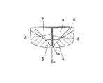
- FIG. 2 is a cross-sectional view taken along line AA in FIG.
- FIG. 3 is a cross-sectional view taken along line BB in FIG.
- FIG. 2 is a cross-sectional view taken along line AA in FIG.
- FIG. 3 is a cross-sectional view taken along line BB in FIG.
- FIG. 2 is a cross-sectional view taken along line AA in FIG.
- FIG. 3 is a cross-sectional view taken along line BB in FIG.
- It is a perspective view which shows the structure of the right side clamping member used for the nipper of FIG.
- It is a perspective view which shows the structure of the left side clamping member used for the nipper of FIG.
- It is a partial expansion perspective view which shows the state in which the nipper of FIG. 1 has clamped the cutting piece.
- It is a partial expansion perspective view which shows the modification
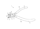
- FIG. 1 is a perspective view showing an external configuration of a nipper according to an embodiment of the present invention.
- FIG. 2 is a perspective view showing a state in which the cutting blade of the nipper according to the embodiment is opened.
- the nipper 1 according to the present embodiment is configured such that a pair of left and right stays 2a and 2b are pivotally attached at an intermediate portion so as to be freely opened and closed.
- the pivot attachment portion 3 to which the pair of left and right stays 2a and 2b pivots is a combination of the left and right stays in the vertical direction and pivotally attached to the pivot shaft 3a.
- the pivot shaft 3 a is fixed by fitting a shaft portion 3 b provided on the stay 2 a located on the lower side in the drawing to the stay 2 b located on the upper side in the drawing. Further, as will be described later, the shaft portion 3b is provided with a screw hole 3c for attaching the clamping members 7a and 7b.
- the stays 2a and 2b are formed in a rod shape, and a grip portion 4 and a blade portion 5 are provided at the ends thereof.
- the stays 2a and 2b are made of at least a metal from the blade part 5 to the pivot part 3 provided at the end part.
- the grip portion 4 is made of stainless steel, resin, or the like, and is configured by fixing the stay 2a integrally or separately. Further, the grip 4 may be provided with a non-slip material such as rubber or resin for reasons such as anti-slip.
- the blade portion 5 is provided in a concave groove 6 formed on the opposite side surfaces of the stays 2a and 2b, and the meshing portion of the blade portions 5 of the left and right stays 2a and 2b is a cutting blade 5a. As shown in FIG. 5, the blade portion 5 is provided to be inclined with respect to the extending direction of the stays 2 a and 2 b.
- the cutting blade 5a is provided with a predetermined length dimension in the extending direction of the stays 2a and 2b, and is configured to have a blade span of about 1.5 cm in this embodiment.
- the cutting blade 5a is configured in a straight line, but is not limited thereto, and may be configured in a curved line.
- a holding portion 8 made of a metal plate extending along the extending direction of the cutting blade 5a is erected.
- the sandwiching portions 8 are arranged so as to face each other, and the opposing surfaces are sandwiched surfaces.
- the lower end 8a of the clamping part 8 is provided close to the cutting blade 5a, it is arrange
- the sandwiching portion 8 is supported by the support portion 9 so as to be movable in a direction intersecting the extending direction of the cutting blade 5a.
- the support portion 9 is configured integrally with the holding portion 8 and is formed of a thin metal plate bent at an angle of about 90 degrees with respect to the holding portion.
- the fold line 9a is configured to be substantially parallel to the pivot shaft 3a.
- the sandwiching portion 8 and the support portion 9 configured as described above act like a leaf spring, and the support portion 8 extends in the extending direction of the cutting blade 5a as shown by an arrow 90 in FIG. Can be rotated in a direction intersecting with.
- the sandwiching portion 8 and the support portion 9 are configured as a part of sandwiching members 7 a and 7 b that are detachably attached to the nipper 1. As shown in FIGS. 7 and 8, the sandwiching members 7 a and 7 b are configured by bending a single metal plate.
- the left and right clamping members 7a and 7b constitute respective parts including a holding part 8 and a supporting part 9 by bending a single metal plate.
- the holding members 7a and 7b include the holding portion 8 and the support portion 9, as well as the attachment portion 10 and the shift prevention stopper 11.
- the metal plates constituting the left and right clamping members 7a and 7b may be any metal plate that can ensure the spring property at the bending line 9a described later, and a stainless steel plate, steel plate, aluminum plate having a thickness of about 0.2 to 1 mm is preferable. Used for. In the present embodiment, a 0.5 mm stainless plate is used.
- the sandwiching portion 8 is a flat plate having a substantially triangular shape, and the lower end 8a thereof is an inclined side along the inclination angle of the cutting blade 5a.
- the support portion 9 is a substantially trapezoidal member having a main surface perpendicular to the holding portion 8.
- the support portion 9 is accommodated in the concave groove 6 of the nipper so as to be close to the pivot attachment portion 3.
- the mounting portion 10 is provided in a state of being bent in the vertical direction with respect to the support portion 9 and is configured to be laminated on the upper surface of the pivoting portion 3 of the nipper.
- the mounting portion 10 is provided with a screw insertion hole 10a.
- the slip prevention stopper 11 is for preventing the left and right clamping members 7a and 7b from being displaced, and has an engagement wall 11a that can be engaged with the side surface of the neck portion 4a of the grip portion 4.
- each clamping member 7a, 7b is provided on the pivot shaft 3a by laminating the right clamping member 7a on the left clamping member 7b and inserting screws 12 into the respective screw insertion holes 10a.
- the screw hole 3c is screwed.
- the clamping members 7 a and 7 b attached to the nippers have the engaging wall 11 a of the slip prevention stopper 11 engaged with the neck portion 4 a of the grip portion 4, and the support portion 9 and the holding portion 8 are the concave grooves 6 of the blade portion 5. Housed inside.
- the sandwiching portion 8 is arranged in a standing state so as to extend along the cutting blade 5a.
- the holding portion 8 it is not necessary to completely fix the holding portion 8 above the cutting blade 5a. For example, a slight play can be allowed in the holding portion 8 so that a large-diameter cutting piece can be held.
- the holding portion 8 it is possible to allow the holding portion 8 to have play by adjusting the tightening strength of the screw 12 by providing the stopper 11 capable of preventing slippage to the neck 4a.
- the clamping members 7a and 7b By attaching the clamping members 7a and 7b to the pivot shaft 3a with screws as described above, the clamping members 7a and 7b can be easily detached, and the support portion 9 and the holding portion are placed at appropriate positions. 8 can be arranged. Therefore, even when the clamping members 7a and 7b have deteriorated over time, the support part 9 and the clamping part 8 can be arranged at appropriate positions by exchanging the clamping members 7a and 7b.
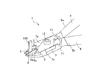
- FIG. 9 is a partially enlarged perspective view showing a state in which the nipper according to the present embodiment holds the cut piece.
- the gripping unit 4 is operated to place the cutting object between the cutting blades 5a of the blade part 5, and the cutting part 5 is closed by the cutting blade. Cut the object to be cut.
- the holding portion 8 comes into contact with the object to be cut.
- the sandwiching portion 8 moves in a direction intersecting the extending direction of the cutting blade 5a with the folding line 9a as the center, and the operation of the blade portion 5 and the clamping of the object to be cut are performed. maintain.
- the cutting piece 100 is sandwiched by the sandwiching part 8, so that the cutting piece 100 can be prevented from scattering and dropping off.
- FIG. 10 is a diagram showing a configuration of a nipper according to a modification.
- the nipper according to the modification employs a sandwiching portion 8 and a support portion 9 that are bent into an L shape, and the support portion 9 is directly fixed to the side wall 6a of the recessed groove 6 on the pivot shaft side. .
- grip part can be erected in the position along a cutting blade, and can be hold
- the plate-like sandwiching portion is erected at a position along the cutting blade, so that when the cutting blade is engaged, the holding surfaces of each other are in close contact with each other.
- the cutting part is held by the support part so as to be movable in a direction intersecting the cutting blade, when the cutting blade closes when the cutting object is cut, it is sandwiched between the holding surfaces. Even after this, the cut piece can be maintained in its held state. Therefore, even when the holding portion is in close contact, the cutting operation by the cutting blade is not hindered, and the operability can be improved.
- the support part supports the holding part so as to be movable in a direction intersecting the cutting blade, so that the holding part can be configured in a plate shape, and it is good at the time of operation without concealing the blade edge. High visibility can be secured.
- this invention is not limited to the said embodiment, It can implement in another various aspect.
- a nipper has been described as an example of a cutting tool.
- a pair of gripping parts such as pliers, radio pliers, and scissors is pivotally attached, and a cutting tool that opens and closes by operating the gripping part is used. Widely applicable.
- the sandwiching portion and the support portion are configured so that the sandwiching portion is erected at a position along the cutting blade and intersects the cutting blade.
- the structure is not particularly limited as long as it can be held movably.
- the support portion may be configured to be movable with the front end side of the holding portion as a rotation axis.
Landscapes
- Life Sciences & Earth Sciences (AREA)
- Forests & Forestry (AREA)
- Engineering & Computer Science (AREA)
- Mechanical Engineering (AREA)
- Scissors And Nippers (AREA)
Applications Claiming Priority (2)
| Application Number | Priority Date | Filing Date | Title |
|---|---|---|---|
| JP2013-134471 | 2013-06-27 | ||
| JP2013134471A JP5856586B2 (ja) | 2013-06-27 | 2013-06-27 | 切断具 |
Publications (1)
| Publication Number | Publication Date |
|---|---|
| WO2014207962A1 true WO2014207962A1 (ja) | 2014-12-31 |
Family
ID=52141344
Family Applications (1)
| Application Number | Title | Priority Date | Filing Date |
|---|---|---|---|
| PCT/JP2013/084852 Ceased WO2014207962A1 (ja) | 2013-06-27 | 2013-12-26 | 切断具 |
Country Status (3)
| Country | Link |
|---|---|
| JP (1) | JP5856586B2 (enExample) |
| TW (1) | TWI616285B (enExample) |
| WO (1) | WO2014207962A1 (enExample) |
Families Citing this family (1)
| Publication number | Priority date | Publication date | Assignee | Title |
|---|---|---|---|---|
| DE102016101927A1 (de) * | 2016-02-04 | 2017-08-10 | Knipex-Werk C. Gustav Putsch Kg | Zange |
Citations (5)
| Publication number | Priority date | Publication date | Assignee | Title |
|---|---|---|---|---|
| JPS63136577U (enExample) * | 1987-02-27 | 1988-09-08 | ||
| JPH01138371U (enExample) * | 1988-03-18 | 1989-09-21 | ||
| JPH0456819A (ja) * | 1990-06-22 | 1992-02-24 | Canon Inc | 光検出装置 |
| JP3021578U (ja) * | 1995-08-10 | 1996-02-27 | 尚 稲福 | 挟持機能つき鋏 |
| JP2002373510A (ja) * | 2001-06-14 | 2002-12-26 | Ichikoh Ind Ltd | ヘッドランプ |
Family Cites Families (6)
| Publication number | Priority date | Publication date | Assignee | Title |
|---|---|---|---|---|
| US2985957A (en) * | 1952-01-15 | 1961-05-30 | Freedman Jesse | Cutting tools and detachable work-holders therefor |
| US2775032A (en) * | 1953-10-19 | 1956-12-25 | Edgar P Sorensen | Workpiece-holding pruning shears with resilient in-drawing gripper element |
| US2938266A (en) * | 1959-04-30 | 1960-05-31 | Mathias Klein & Sons | Oblique cutting plier |
| US3777398A (en) * | 1972-01-20 | 1973-12-11 | E Routh | Wire cutting tool |
| US4326334A (en) * | 1980-09-11 | 1982-04-27 | Roux Steven J | Hand held restraining cutter |
| US5398415A (en) * | 1994-08-22 | 1995-03-21 | Collins, Jr.; Moseley C. | Cutter with gripper |
-
2013
- 2013-06-27 JP JP2013134471A patent/JP5856586B2/ja active Active
- 2013-08-19 TW TW102129664A patent/TWI616285B/zh active
- 2013-12-26 WO PCT/JP2013/084852 patent/WO2014207962A1/ja not_active Ceased
Patent Citations (5)
| Publication number | Priority date | Publication date | Assignee | Title |
|---|---|---|---|---|
| JPS63136577U (enExample) * | 1987-02-27 | 1988-09-08 | ||
| JPH01138371U (enExample) * | 1988-03-18 | 1989-09-21 | ||
| JPH0456819A (ja) * | 1990-06-22 | 1992-02-24 | Canon Inc | 光検出装置 |
| JP3021578U (ja) * | 1995-08-10 | 1996-02-27 | 尚 稲福 | 挟持機能つき鋏 |
| JP2002373510A (ja) * | 2001-06-14 | 2002-12-26 | Ichikoh Ind Ltd | ヘッドランプ |
Also Published As
| Publication number | Publication date |
|---|---|
| JP5856586B2 (ja) | 2016-02-10 |
| JP2015008769A (ja) | 2015-01-19 |
| TWI616285B (zh) | 2018-03-01 |
| TW201500149A (zh) | 2015-01-01 |
Similar Documents
| Publication | Publication Date | Title |
|---|---|---|
| US8028419B2 (en) | Folding knife or tool | |
| US20090007733A1 (en) | Clamping and cutting apparatus with adjustable head | |
| US9845817B2 (en) | Clamping system | |
| WO2011004701A1 (ja) | 切断機におけるガード部材の固定具脱落防止構造 | |
| US8607460B1 (en) | Single spring arm assisted knife | |
| TW201818626A (zh) | 切斷工具 | |
| JP5856586B2 (ja) | 切断具 | |
| JP2019005920A (ja) | 定規用アダプタ | |
| US8701528B2 (en) | Ratchet-action open-end wrench | |
| JP5816764B2 (ja) | ニッパ | |
| US9841040B2 (en) | Clamping system | |
| CN104968478B (zh) | 线材用切割器 | |
| JP6656880B2 (ja) | カバー付き清掃具のカバー開閉方法及びカバー付き清掃具 | |
| JP2015016543A (ja) | ピンセット | |
| CN112771741B (zh) | 间接火线工程用把持工具 | |
| JP2008011977A (ja) | 手動工具 | |
| JP2009050053A (ja) | 間接活線把持工具 | |
| CN107690275B (zh) | 包括第一剪切部分及第二剪切部分的剪刀 | |
| JP2018011471A (ja) | 間接活線工事用クリップ | |
| TWM517083U (zh) | 剪切工具安全省力機構 | |
| JP5886169B2 (ja) | プライヤ | |
| JP7281516B2 (ja) | 作業補助装置 | |
| KR20120006844U (ko) | 플라이어 | |
| JP2011051041A (ja) | 把持用手動工具 | |
| CN120228314A (zh) | 螺杆切割机构和电动工具 |
Legal Events
| Date | Code | Title | Description |
|---|---|---|---|
| 121 | Ep: the epo has been informed by wipo that ep was designated in this application |
Ref document number: 13887606 Country of ref document: EP Kind code of ref document: A1 |
|
| NENP | Non-entry into the national phase |
Ref country code: DE |
|
| 122 | Ep: pct application non-entry in european phase |
Ref document number: 13887606 Country of ref document: EP Kind code of ref document: A1 |