WO2014203992A1 - 板材の端部の処理方法、板材の製造方法、板材の端部の処理装置、及び、板材 - Google Patents
板材の端部の処理方法、板材の製造方法、板材の端部の処理装置、及び、板材 Download PDFInfo
- Publication number
- WO2014203992A1 WO2014203992A1 PCT/JP2014/066418 JP2014066418W WO2014203992A1 WO 2014203992 A1 WO2014203992 A1 WO 2014203992A1 JP 2014066418 W JP2014066418 W JP 2014066418W WO 2014203992 A1 WO2014203992 A1 WO 2014203992A1
- Authority
- WO
- WIPO (PCT)
- Prior art keywords
- plate material
- thin
- board
- outer peripheral
- main body
- Prior art date
- Legal status (The legal status is an assumption and is not a legal conclusion. Google has not performed a legal analysis and makes no representation as to the accuracy of the status listed.)
- Ceased
Links
Images








Classifications
-
- B—PERFORMING OPERATIONS; TRANSPORTING
- B29—WORKING OF PLASTICS; WORKING OF SUBSTANCES IN A PLASTIC STATE IN GENERAL
- B29C—SHAPING OR JOINING OF PLASTICS; SHAPING OF MATERIAL IN A PLASTIC STATE, NOT OTHERWISE PROVIDED FOR; AFTER-TREATMENT OF THE SHAPED PRODUCTS, e.g. REPAIRING
- B29C67/00—Shaping techniques not covered by groups B29C39/00 - B29C65/00, B29C70/00 or B29C73/00
- B29C67/0044—Shaping techniques not covered by groups B29C39/00 - B29C65/00, B29C70/00 or B29C73/00 for shaping edges or extremities
-
- B—PERFORMING OPERATIONS; TRANSPORTING
- B29—WORKING OF PLASTICS; WORKING OF SUBSTANCES IN A PLASTIC STATE IN GENERAL
- B29C—SHAPING OR JOINING OF PLASTICS; SHAPING OF MATERIAL IN A PLASTIC STATE, NOT OTHERWISE PROVIDED FOR; AFTER-TREATMENT OF THE SHAPED PRODUCTS, e.g. REPAIRING
- B29C69/00—Combinations of shaping techniques not provided for in a single one of main groups B29C39/00 - B29C67/00, e.g. associations of moulding and joining techniques; Apparatus therefore
- B29C69/001—Combinations of shaping techniques not provided for in a single one of main groups B29C39/00 - B29C67/00, e.g. associations of moulding and joining techniques; Apparatus therefore a shaping technique combined with cutting, e.g. in parts or slices combined with rearranging and joining the cut parts
-
- B—PERFORMING OPERATIONS; TRANSPORTING
- B29—WORKING OF PLASTICS; WORKING OF SUBSTANCES IN A PLASTIC STATE IN GENERAL
- B29C—SHAPING OR JOINING OF PLASTICS; SHAPING OF MATERIAL IN A PLASTIC STATE, NOT OTHERWISE PROVIDED FOR; AFTER-TREATMENT OF THE SHAPED PRODUCTS, e.g. REPAIRING
- B29C53/00—Shaping by bending, folding, twisting, straightening or flattening; Apparatus therefor
- B29C53/02—Bending or folding
- B29C53/04—Bending or folding of plates or sheets
-
- B—PERFORMING OPERATIONS; TRANSPORTING
- B29—WORKING OF PLASTICS; WORKING OF SUBSTANCES IN A PLASTIC STATE IN GENERAL
- B29K—INDEXING SCHEME ASSOCIATED WITH SUBCLASSES B29B, B29C OR B29D, RELATING TO MOULDING MATERIALS OR TO MATERIALS FOR MOULDS, REINFORCEMENTS, FILLERS OR PREFORMED PARTS, e.g. INSERTS
- B29K2101/00—Use of unspecified macromolecular compounds as moulding material
- B29K2101/12—Thermoplastic materials
-
- B—PERFORMING OPERATIONS; TRANSPORTING
- B29—WORKING OF PLASTICS; WORKING OF SUBSTANCES IN A PLASTIC STATE IN GENERAL
- B29K—INDEXING SCHEME ASSOCIATED WITH SUBCLASSES B29B, B29C OR B29D, RELATING TO MOULDING MATERIALS OR TO MATERIALS FOR MOULDS, REINFORCEMENTS, FILLERS OR PREFORMED PARTS, e.g. INSERTS
- B29K2105/00—Condition, form or state of moulded material or of the material to be shaped
- B29K2105/25—Solid
- B29K2105/253—Preform
- B29K2105/256—Sheets, plates, blanks or films
Definitions
- the present invention relates to a method for treating an end portion of a plate material made of a thermoplastic resin (for example, resin cardboard, etc .; hereinafter also referred to as “resin plate material” for convenience), a method for producing a resin plate material, and an end of the resin plate material.
- the present invention relates to a processing apparatus and a resin plate material.
- resin plate materials have been used for various purposes (for example, flooring materials for automobile trunk rooms).
- the resin plate material is cut into a desired shape according to its application, and then variously applied to the end portion (terminal portion) including the cut surface from the viewpoint of improving the aesthetics of the resin plate material and reducing the sense of harm. It is manufactured through a process in which the above process is performed.
- one of the conventional processing methods forms notches having a specific shape on the pressed surface while heating and pressing the end portion of a plate made of synthetic resin.
- the conventional method prevents the cut surface from being exposed at the end of the plate material, and enhances the aesthetics of the plate material (see, for example, Patent Document 1).
- the shape of the notch provided in the end portion of the plate material is set to a specific shape so that the cut surface of the end portion is stored inside the plate material as the end portion is folded. That is, the conventional method is based on the premise that “the entire cut surface of the end portion of the plate is always stored inside the plate by the operation of folding the end”.
- the entire cut surface is not necessarily made of the plate material. It is considered that a part of the cut surface may be exposed on the surface of the plate material without being housed inside. In that case, there is a possibility that the aesthetics of the plate material may not be improved as expected.
- the present invention provides a method for treating an end of a resin plate that can prevent the end (cut surface) of the resin plate from being exposed to the surface of the resin plate as easily and reliably as possible. It is providing the manufacturing method of the resin board material using the method, the processing apparatus of the edge part of the resin board material which performs the processing method, and a resin board material.
- the method for treating an end portion of a plate material according to the present invention to achieve the above-described problem is applied to a plate material made of a thermoplastic resin.
- This processing method is (1) a first step of forming a thin portion by heating and pressing the end of the plate material in the thickness direction; (2) Fold the thin portion so that the pressed surface is inside, and connect the outer peripheral end, which is the outer peripheral end of the thin portion, to the inner end, which is the inner end of the thin portion of the thin plate.
- the outer peripheral end of the thin portion moves toward the main body portion of the plate material.
- the cut surface of the plate material does not exist at the end portion (outer edge portion) of the plate material.
- the third step moves the outer peripheral end of the thin portion (the end including the cut surface of the plate) to the inner side in the thickness direction than the surface of the main body (in other words, not to be exposed to the outside of the plate). To do.
- the outer peripheral edge of the thin portion is exposed to the surface of the plate material due to the above-described various variations (variations in processing accuracy in the first step and the second step, variations in the dimensions of the plate material itself, etc.). Even so, in the third step, the outer peripheral edge including the exposed portion is embedded inside the plate. In addition, moving the outer peripheral end of the thin portion in the thickness direction generally does not require a complicated method, so the third step can be easily performed. Therefore, according to the above configuration, the outer peripheral end of the thin portion is easily and reliably prevented from being exposed on the surface of the plate material.
- the processing accuracy required in the third step is the first step (heat pressing of the end portion of the plate material) and the second step (of the thin portion). It is lower than the processing accuracy required for folding. In other words, even if there is some variation in the processing accuracy in the third step (for example, the amount of movement of the outer peripheral edge of the thin part), it is sufficient that the outer peripheral edge of the thin part is exposed on the surface of the plate material. It is prevented.
- the end of the main body of the plate (the boundary between the thin portion and the main body) is exposed on the surface of the plate, and the end of the main body is exposed to the aesthetics and danger of the plate. May be affected.
- this end portion is formed by pressing the plate material (see the first step and the second step).
- the end surface and the corner portion are compared to the end portion (cut surface) of the plate material.
- the shape is more gradual (for example, the radius of curvature of the corner portion at the end of the main body is larger than the radius of curvature of the corner portion of the cut surface). Therefore, in terms of improving the aesthetics of the plate material and reducing the sense of harm, the merit of preventing the exposure of the end portion (cut surface) of the plate material exceeds the demerit of exposing the end portion of the main body portion.
- the processing method of the present invention can easily and reliably prevent the end (cut surface) of the resin plate material from being exposed on the surface of the resin plate material. Furthermore, this can improve the aesthetics of the plate material and reduce the sense of harm.
- the “plate material” to which the treatment method of the present invention is applied may be a plate-like body made of a thermoplastic resin, and the shape, internal structure, specific type of resin, etc. are not particularly limited.
- a resin cardboard, a polystyrene foam board, etc. can be employ
- the end portion of the plate material is heated and pressed, so that the thin-walled portion (the heated and pressed portion) is directed from the main body portion (the portion that is not heated and pressed) toward the terminal portion of the plate material. It will be configured to stretch. Therefore, the first step can be rephrased as, for example, “a step of heating and pressing the end portion of the plate material in the thickness direction to form a thin portion extending from the main body portion of the plate material toward the outer periphery of the plate material”.
- the “pressing” in the first step may be a process that exerts an external force in the direction in which the plate material is compressed against the surface of the plate material (direction in which the thickness of the plate material is reduced; thickness direction).
- a mode of pressing a process of pressing the pressing body against the plate material from the outside while fixing the plate material to be immovable can be mentioned.
- plate material to a press body while fixing a press body immovably is also mentioned.
- plate material and a press body and presses them mutually is also mentioned. The same applies to “pressing” in the third step.
- the expression “moving the outer peripheral edge of the thin part to the vicinity of the main body of the plate” means that the outer peripheral edge of the thin part is in the vicinity of the main body when the thin part is folded.
- the outer peripheral end of the thin wall portion and the main body portion do not necessarily need to be in close contact or adjacent to each other. This expression can be rephrased as, for example, moving the outer peripheral end of the thin portion to a position away from the outer periphery of the plate member.
- the thin-walled portion is connected to the main body of the plate material at the inner end. Therefore, when the outer peripheral end of the thin portion is moved to the vicinity of the main body portion of the plate material in the second step, the outer peripheral end of the thin portion is also moved to the vicinity of the inner end of the thin portion. Therefore, the above expression can be paraphrased as, for example, moving the outer peripheral end of the thin portion to the vicinity of the inner end.
- the “pressing” of the outer peripheral edge of the thin portion in the third step may be a pressing with heating (heating pressing) or a pressing without heating.
- the pressing in the third step may be performed while the original heat does not accompany the residual heat from the heating and pressing in the first step. The same applies to “folding” in the second step.
- the expression “inner side in the thickness direction than the surface of the main body” means that the virtual plane extending the surface of the main body is defined as the reference plane in the pressing direction (thickness direction) from the same reference plane. It can be rephrased as a distant position.
- the same expression is used between the front surface and the back surface of the plate material (strictly, before processing into a thin portion in the first step (before the first step is performed), In other words, the position between the front surface and the back surface).
- the expression that the outer peripheral end of the thin portion is “moved inward in the thickness direction from the surface of the main body portion” is an imaginary surface in which the outer peripheral end of the thin portion is extended from the surface of the main body portion ( In other words, it moves to a position that is further away in the pressing direction (thickness direction) than the reference plane.
- the same expression can be paraphrased that the outer peripheral end of the thin portion is moved between the front surface and the back surface of the plate material.
- the same expression makes the thickness of the thin portion at the position where the outer peripheral edge of the thin portion exists (thickness in the pressing direction of the thin portion folded through the second step) smaller than the thickness of the main body portion. In other words.
- the “surface of the main body” described above is a plane perpendicular to the thickness direction (pressing direction) of the plate material among the planes defining the main body, and is the same side as the pressed surface of the thin portion. It can be rephrased as a plane existing in Further, in general, a plate material (for example, a plate material as a product) that has undergone this processing method has a surface on the same side as the pressed surface of the thin-walled portion as the back surface and a surface opposite to the pressed surface of the thin-walled portion. It is often handled as a front surface (so-called design surface).
- the “front surface” of the plate material is a plane perpendicular to the thickness direction (pressing direction) of the plate material among the planes that define the plate material, and exists on the opposite side of the pressed surface of the thin portion. It can be paraphrased as a surface.
- the “back surface” of the plate material is a plane perpendicular to the thickness direction (pressing direction) of the plate material among the planes defining the plate material, and is a surface existing on the same side as the pressed surface of the thin portion, and In other words.
- the degree of pressing in the third step (for example, the amount of movement of the outer peripheral edge of the thin portion due to pressing, the range of the thin portion to be pressed, the cross-sectional shape of the final plate material, etc.)
- the degree of harm reduction There is no particular limitation as long as it is determined appropriately in consideration of the degree, the degree of harm reduction, the internal structure of the plate material, the thickness of the plate material, and the like (see, for example, each aspect described later).
- the outer peripheral end of the thin portion moves to the inside in the thickness direction from the surface of the main body portion.
- the intention of bulging and burrs around the outer peripheral end is intended. It is thought that there is a case where there is a deformation. From the viewpoint of further improving the aesthetics of the plate material, it is preferable to prevent such deformation.
- the thin portion may be formed such that the pressed surface has a recess around the inner end of the thin portion.
- the outer peripheral end of the thin portion when the outer peripheral end of the thin portion is pressed in the third step, the outer peripheral end of the thin portion enters (inflows) into the gap (concave portion).
- the treatment method of this aspect can further improve the aesthetics of the plate material while easily and reliably preventing the end (cut surface) of the resin plate material from being exposed to the surface of the resin plate material.
- the “concave portion” provided on the pressed surface of the thin-walled portion may be a portion where the thickness of the thin-walled portion is thinner than the periphery thereof, and the width, depth, and cross-sectional shape of the concave portion are not particularly limited.
- the width, depth, and cross-sectional shape of the recesses are, for example, in consideration of the thickness and cross-sectional shape of the plate material and the type of resin constituting the plate material so that the unintentional deformation described above is sufficiently prevented. It may be determined.
- the outer peripheral end of the thin portion is pressed in the thickness direction. At this time, it is not always necessary to press only the outer peripheral end of the thin portion, and a portion existing around the outer peripheral end may be pressed in addition to the outer peripheral end of the thin portion.
- a portion of the main body portion around the outer peripheral end of the thin portion can also be pressed in the thickness direction.
- the boundary (end part of a main-body part) of a thin part and a main-body part moves to the inner side of thickness direction rather than the surface of a main-body part (for example, refer FIG.7 and FIG.14). ).
- This makes it difficult for the boundary to be visually recognized, and makes it difficult for the user's finger or the like to touch the boundary.
- the treatment method of this aspect further improves the aesthetics of the plate material and further reduces the sense of harm while further easily and reliably preventing the end (cut surface) of the resin plate material from being exposed on the surface of the resin plate material. can do.
- the degree of pressing in this aspect may be appropriately determined in consideration of the degree of aesthetics required for the plate material, the degree of reduction in the sense of harm, the internal structure of the plate material, the thickness of the plate material, etc. There is no particular limitation.
- the processing method (Aspect 3) of the present invention In the third step, only the outer peripheral end (or the periphery of the outer peripheral end) of the thin portion can be pressed such that a concave portion in which the outer peripheral end of the thin portion is buried inside the plate member is formed.
- this recessed part (dent) etc. is suitably determined in consideration of the degree of aesthetics required for the plate material, the degree of reduction of the sense of harm, the internal structure of the plate material, the thickness of the plate material, etc., as described above. Well, not particularly limited.
- the width of the recess (indentation) (the width of the plate material in the direction from the main body to the outer periphery) makes it difficult to visually recognize the recess and makes it difficult for a user's finger or the like to enter the interior of the recess. Therefore, it is preferable in terms of improving the aesthetics of the plate material and reducing the sense of harm.
- the entire thin portion including the outer peripheral end of the thin portion can be pressed in the thickness direction.
- the outer peripheral end (or the periphery thereof) of the thin portion can be prevented from being locally pressed as compared with the case where the outer peripheral end of the thin portion is buried (embodiment 3) (for example, , Refer to FIG. 15), and it is possible to further reliably prevent unintended deformation (swelling, burrs, etc.) from occurring around the outer peripheral edge of the thin portion.
- a flat portion (a portion where the thin portion is pressed) having a thickness smaller than that of the main body portion is formed around the plate material.
- the processing methods of these aspects further improve the aesthetics of the plate material and further reduce the sense of harm while further easily and reliably preventing the end (cut surface) of the resin plate material from being exposed on the surface of the resin plate material. can do.
- the plate material to which the treatment method of the present invention is applied does not necessarily need to be composed of only a thermoplastic resin, and may include a portion composed of another material.
- a buffer layer may be provided on both main surfaces of the plate.
- the outer peripheral end of the thin portion when the outer peripheral end of the thin portion is pressed in the thickness direction in the third step, the outer peripheral end (cut surface) of the thin portion is covered with the buffer layer.
- the outer peripheral end (cut surface) of the thin-walled portion becomes more difficult to be visually recognized, and the user's finger or the like is further less likely to contact the outer peripheral end of the thin-walled portion.
- the processing method of this aspect further improves the aesthetics of the plate material and further reduces the sense of danger while easily and reliably preventing the end (cut surface) of the resin plate material from being exposed to the surface of the resin plate material. be able to.
- main surface of the plate material represents a surface excluding the side surface of the surface of the plate material (that is, the front surface and the back surface).
- a main surface can be paraphrased as a surface perpendicular
- the “buffer layer” may be a layered body that protects the main surface of the plate from the surroundings, and the material constituting the buffer layer, the thickness of the buffer layer, and the like are not particularly limited.
- a layered body composed of a nonwoven fabric can be adopted as the buffer layer.
- the edge portion of the plate is appropriately processed and the aesthetics are improved.
- a plate material with a reduced sense of harm can be easily and reliably manufactured.
- the method for producing a plate material according to the present invention for achieving the above-described problem is as follows. Cutting the plate material into a predetermined shape; A first process for forming a thin portion by heating and pressing the end portion of the plate material in the thickness direction, and folding the thin portion so that the pressed surface is inside, at the end portion of the thin portion on the outer peripheral side of the plate member A second process for moving a certain outer peripheral end to the vicinity of the main body of the plate member to which the inner end, which is an inner end of the thin member, is pressed, and pressing the outer peripheral end of the thin member in the thickness direction And a third treatment that moves the inner side in the thickness direction from the surface of the main body, and Is included.
- the thin portion may be formed such that the pressed surface has a recess around the inner end of the thin portion.
- a portion of the main body portion around the outer peripheral end of the thin-walled portion can also be pressed in the thickness direction.
- the third treatment only the outer peripheral end (or the periphery of the outer peripheral end) of the thin portion can be pressed so that a concave portion is formed in which the outer peripheral end of the thin portion is buried inside the plate member.
- the entire thin portion including the outer peripheral end of the thin portion can be pressed in the thickness direction.
- a buffer layer may be provided on both main surfaces of the plate.
- plate material by this invention can be further improved in viewpoints, such as the aesthetics of a board
- the processing device that executes the above processing method of the present invention is improved in aesthetics by appropriately processing the edge portion. At the same time, it is possible to easily and reliably produce a plate material with a reduced sense of harm.
- a processing apparatus for an end portion of a plate material according to the present invention for achieving the above-described problem is as follows.
- An apparatus for processing an end portion of a plate material composed of a thermoplastic resin A first mechanism that heats and presses an end of the plate in the thickness direction to form a thin portion; The thin-walled portion is folded so that the pressed surface is inside, and the outer peripheral end, which is the end portion of the thin-walled portion on the outer peripheral side of the plate member, is connected to the inner end, which is the end portion of the thin-walled portion on the inner side of the plate member.
- a second mechanism for moving to the vicinity of the main body of the plate A third mechanism for pressing the outer peripheral end of the thin portion in the thickness direction and moving the inner portion in the thickness direction from the surface of the main body portion; It has.
- the processing apparatus of the present invention can appropriately and reliably manufacture the edge of the resin plate material, and easily and reliably produce an excellent plate material in terms of improving aesthetics and reducing the sense of harm.
- the first mechanism may form the thin portion so that the pressed surface has a recess around the inner end of the thin portion.
- the third mechanism together with the outer peripheral end of the thin portion, can press a portion of the main body portion around the outer peripheral end of the thin portion in the thickness direction.
- the third mechanism can press only the outer peripheral end (or the periphery of the outer peripheral end) of the thin portion so that the outer peripheral end of the thin portion forms a recess embedded in the plate member.
- the third mechanism may press the entire thin portion including the outer peripheral end of the thin portion in the thickness direction.
- a buffer layer may be provided on both main surfaces of the plate.
- plate material by this invention can be further improved in viewpoints, such as the aesthetics of a board
- the plate material subjected to the above-described treatment method of the present invention has an appropriately processed end portion treatment structure, and Excellent in terms of improving aesthetics and reducing harm.
- the plate material according to the present invention for achieving the above-described problems is A plate material comprising an end processing structure composed of a thermoplastic resin and processed at the end,
- the end treatment structure is
- the plate member has a main body portion, and a thin-walled portion extending from the main-body portion is curved, and the thin-walled portion is curved so that a distal end portion of the thin-walled portion moves to the vicinity of the main-body portion.
- the thin-walled portion has a structure in which the tip portion of the thin-walled portion moves to the inside in the thickness direction from the surface of the main body portion.
- the plate material of the present invention has an appropriately processed end portion, and is excellent in aesthetics and can reduce the sense of harm.
- a portion of the main body portion around the tip portion of the thin portion moves together with the tip portion of the thin portion inward in the thickness direction from the surface of the main body portion.
- a buffer layer may be provided on both main surfaces of the plate.
- plate material by this invention can be made further higher in viewpoints, such as aesthetics.
- the “processing method of the end portion of the plate material” according to the present invention can prevent the end portion (cut surface) of the resin plate material from being exposed to the surface of the resin plate material as easily and reliably as possible. There is an effect that it is possible.
- the “plate material manufacturing method” according to the present invention has an effect that an end portion is appropriately processed to improve aesthetics and easily and reliably manufacture a plate material with a reduced sense of harm.
- the “processing apparatus for the end portion of the plate material” according to the present invention can easily and surely improve the aesthetics of the plate material and reduce the sense of harm by appropriately processing the end portion of the plate material. There is an effect that can be.
- the “plate material” according to the present invention has an effect that it is excellent in aesthetics and is less harmful.
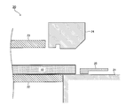
- FIG. 1 It is a schematic sectional drawing which shows the example of the board
- FIG. 1 shows a schematic configuration of a plate material (plate material before being processed) to which a processing method (first processing method) according to the present embodiment is applied.
- the plate member 10 includes a plate-like body 11 and a buffer layer 12 provided on the surface (two main surfaces) of the plate-like body 11.
- the plate-like body 11 is made of a thermoplastic resin
- the buffer layer 12 is made of a nonwoven fabric.
- the end surface 11a of the plate-like body 11 is a cut surface formed when the plate material 10 is processed into a shape suitable for its use.
- FIG. 2 shows a schematic configuration of the processing apparatus 20 (first processing apparatus; hereinafter referred to as “apparatus 20”) according to the present embodiment.
- the apparatus 20 includes a fixed lower pad 21, a movable lower pad 22, a movable upper pad 23, a hot blade 24, and a slide cam 25.
- the plate material manufacturing method (first manufacturing method) according to the present embodiment and the processing device (first processing device) for the end portion of the plate material according to the present embodiment as a result
- plate material) which concerns on embodiment is demonstrated.
- the plate material 10 is processed in the order of procedure 1 to procedure 7 described later.
- the upper, lower, left, and right directions on the drawing in each drawing are referred to as “upward”, “downward”, “leftward”, and “rightward”.
- the thin-walled portion 10a formed by the hot blade 24 includes an outer peripheral end (outer peripheral end) 10b, an inner end (internal end) 10c of the plate 10, and a pressure around the inner end 10c. 10 d of recessed parts formed in the surface (upward surface of the thin part 10a).
- the thin portion 10a is connected to the main body portion 10e of the plate 10 at the inner end 10c. That is, the thin-walled portion 10a extends from the main body portion 10e of the plate material 10 in a direction toward the outer periphery (end surface 11a) of the plate material 10.
- this procedure 4 is performed while the remaining heat in the procedure 1 remains in the thin portion 10a (that is, while the thin portion 10a has a degree of plasticity that can be deformed).
- Procedure 5 and Procedure 6 described later The same applies to Procedure 5 and Procedure 6 described later.
- the tip end portion (left end portion) of the slide cam 25 covers not only the outer peripheral end 10b of the thin-walled portion 10a but also a portion existing around the outer peripheral end 10b of the main body portion 10e. Proceed to.
- the outer peripheral end 10b of the thin wall portion moves to the inner side in the thickness direction from the surface of the main body portion 10e (10f in FIG. 8), and the portion existing around the outer peripheral end 10b of the main body portion 10e is also the main body. It moves to the inner side in the thickness direction than the surface of the portion 10e.
- a concave portion is formed in which the outer peripheral end 10b of the thin portion is buried in the plate member 10 (details will be described later).
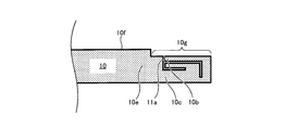
- FIG. 8 is a partial enlarged view of an end portion of the plate member 10 manufactured according to the first processing method according to the present embodiment.
- the plate 10 after processing has an end processing structure shown in FIG. Specifically, in this end portion processing structure, the thin portion 10a is curved so that the distal end portion (outer peripheral end 10b) of the thin portion 10a moves to the vicinity of the main body portion (main body portion 10e), and the thin portion 10a.
- the front end portion (outer peripheral end 10b) of the main body portion (the main body portion 10e) is moved more inward in the thickness direction of the plate material 10 than the surface 10f of the main body portion (main body portion 10e). It is a structure.
- the processing method (second processing method) according to the present embodiment is applied to the same plate material as the plate material 10 to which the processing method (first processing method) according to the first embodiment is applied (see FIG. 1). .
- FIG. 9 shows a schematic configuration of the processing apparatus 30 (second processing apparatus; hereinafter referred to as “apparatus 30”) according to the present embodiment. Similar to the processing apparatus 20 according to the first embodiment, the apparatus 30 includes a fixed lower pad 31, a movable lower pad 32, a movable upper pad 33, a thermal blade 34, and a slide cam 35.
- the procedure for applying the processing method (second processing method) according to the present embodiment to the plate 10 is as follows.
- the thin-walled portion 10a includes an end portion (outer peripheral end) 10b on the outer peripheral side of the plate member 10, an end portion (internal end) 10c on the inner side of the plate member 10, and a recessed portion 10d formed on the pressed surface around the inner end 10c. And have.
- the thin portion 10a (see FIG. 9) is folded so that the pressed surface is inside.
- the gap A formed by the recess 10d exists near the outer peripheral end 10b of the thin-walled portion 10a (for example, between the outer peripheral end 10b and the inner end 10c).
- FIG. 15 is a partially enlarged view of an end portion of the plate 10 manufactured according to the second processing method according to the present embodiment.
- the plate 10 after processing has an end processing structure shown in FIG. Specifically, in this end portion processing structure, the thin portion 10a is curved so that the distal end portion (outer peripheral end 10b) of the thin portion 10a moves to the vicinity of the main body portion (main body portion 10e), and the thin portion 10a.
- the tip end portion (outer peripheral end 10b) of the main body portion (the main body portion 10e) is moved more inward in the thickness direction of the plate material 10 than the surface 10f of the main body portion (main body portion 10e).
- a thin flat portion 10g is present).
- the plate 10 after the above-described processing method generally has the same surface as the pressed surface of the thin portion 10a (the upper surface in FIGS. 8 and 15 to 17) as the “rear surface”,
- the surface opposite to the pressed surface of the portion 10a is often referred to as the “front surface” (so-called design surface).
- a first step for forming the thin portion 10a by heating and pressing the end portion of the plate member 10 in the thickness direction;
- the thin portion 10a is folded so that the pressed surface is inside, and the outer end 10b, which is the end of the thin portion 10a on the outer peripheral side of the plate, is connected to the inner end 10c, which is the end on the inner side of the plate of the thin portion 10a.
- a second step for moving the plate 10 to the vicinity of the main body 10e;
- a third step in which the outer peripheral edge 10b of the thin-walled portion is pressed in the thickness direction and moved to the inner side in the thickness direction than the surface 10f of the main body portion; Is included.
- the thin portion 10a is formed so that the pressed surface (upward surface in FIGS. 4 and 11) has the concave portion 10d around the inner end 10c of the thin portion. Has been.
- a portion of the main body portion 10e that is present around the outer peripheral end 10b of the thin portion is pressed in the thickness direction together with the outer peripheral end 10b of the thin portion.
- the outer peripheral end 10b of the thin portion may be pressed so as to form a recessed portion embedded in the plate member 10 (first embodiment), and the entire thin portion 10a including the outer peripheral end 10b of the thin portion is formed.
- the flat portion 10g may be formed by pressing in the thickness direction (second embodiment).
- a buffer layer (nonwoven fabric layer 12) is provided on both the main surfaces of the plate 10 (upper surface and lower surface in FIG. 1).
- the “plate material manufacturing method” Cutting the plate 10 into a predetermined shape (see FIG. 1); A first process (procedures 2 and 3) for forming the thin portion 10a by heating and pressing the end portion of the plate member 10 in the thickness direction, and the thin portion 10a is folded so that the pressed surface is inside, and the thin portion 10a A second process (procedure) for moving the outer peripheral end 10b, which is the end portion on the outer peripheral side of the plate member 10, to the vicinity of the main body portion 10e of the plate member 10 to which the inner end 10c, which is the inner end portion of the thin plate portion 10a, is connected. 4 and 5) and a third process (procedure 6) for pressing the outer peripheral end 10b of the thin-walled portion in the thickness direction and moving it to the inner side in the thickness direction than the surface 10f of the main body portion. Including.
- the thin portion 10a is formed so that the pressed surface has a recess around the inner end 10c of the thin portion.
- a portion of the main body portion 10e existing around the outer peripheral end 10b of the thin portion is pressed in the thickness direction together with the outer peripheral end 10b of the thin portion.
- the outer peripheral end 10b of the thin portion may be pressed so as to form a recessed portion embedded in the plate member 10 (first embodiment), and the entire thin portion 10a including the outer peripheral end 10b of the thin portion is formed.
- the flat portion 10g may be formed by pressing in the thickness direction (second embodiment).
- the “processing apparatus for the edge of the plate” is Devices 20 and 30 for processing the ends of the plate 10,
- a first mechanism for example, a thermal blade 24 for forming the thin portion 10a by heating and pressing the end portion of the plate material in the thickness direction, and the thin portion 10a is folded so that the pressed surface is inside, and the thin portion 10a
- a second mechanism for moving the outer peripheral end 10b, which is an end portion on the outer peripheral side of the plate material, to the vicinity of the main body portion 10e of the plate material to which the inner end 10c, which is the end portion on the inner side of the plate material of the thin portion 10a, is connected.
- a slide cam 25 for moving the outer peripheral end 10b of the thin portion in the thickness direction to move the inner side in the thickness direction from the surface 10f of the main body portion.
- the first mechanism 24 forms the thin portion 10a so that the pressed surface has a recess 10d around the inner end 10c of the thin portion.
- the third mechanisms 21, 22, and 23 press the portion of the main body portion 10e around the outer peripheral end 10b of the thin portion in the thickness direction together with the outer peripheral end 10b of the thin portion.
- the outer peripheral end 10b of the thin portion may be pressed so as to form a recessed portion embedded in the plate member 10 (first embodiment), and the entire thin portion 10a including the outer peripheral end 10b of the thin portion is formed.
- the flat portion 10g may be formed by pressing in the thickness direction (second embodiment).
- the “plate material” is a plate material (plate material 10 after processing, FIGS. 8 and 15) having an end processing structure in which an end is processed.
- the end portion processing structure has a main body portion 10e of the plate member 10 and a curved portion of the thin portion 10a extending from the main body portion 10e, and the distal end portion (outer peripheral end 10b) of the thin portion 10a is the main body portion 10e.
- the thin-walled portion 10a is curved so as to move to the vicinity, and the tip portion 10b of the thin-walled portion 10a is moved inward in the thickness direction from the surface 10f of the main body portion.
- a portion of the main body portion 10e around the distal end portion 10b of the thin portion moves inward in the thickness direction from the surface 10f of the main body portion 10e together with the distal end portion 10b of the thin portion. Have been configured.
- the plate material 10 of each of the above embodiments has a solid resin plate material as the plate-like body 11.
- the processing method and the manufacturing method of the present invention may be applied to a plate material provided with resin cardboard as the plate-like body 11.
- a concave portion 10d is formed on the pressed surface around the inner end 10c of the thin portion 10a.
- the processing method / manufacturing method of the present invention may be configured to form the thin portion 10a that does not have the concave portion 10d.
- the outer peripheral end 10b of the thin portion 10a and the portion existing around the outer peripheral end 10b of the main body portion 10e are pressed and moved.
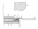
- the treatment method / manufacturing method of the present invention as shown in FIG. 16 or FIG. 17, only the outer peripheral end 10b of the thin wall portion 10a is pressed and moves inward in the thickness direction from the surface 10f of the main body portion. May be configured.
- step 5 of the first embodiment the tip of the slide cam 25 is advanced to a position that covers only the outer peripheral end 10b of the thin portion 10a.
- step 6 only the outer peripheral end 10b of the thin portion 10a is moved. What is necessary is just to press with the slide cam 25.
- step 5 of the second embodiment the tip of the slide cam 35 is advanced to a position that covers only the outer peripheral end 10b of the thin portion 10a.
- step 6 the slide cam 35 is moved to the outer peripheral end 10b of the thin portion 10a. You just need to press it.
- the present invention relates to a method for treating an end of a resin plate that can prevent the end (cut surface) of the resin plate from being exposed to the surface of the resin plate as easily as possible, and a plate using the treatment method.
- This method can be used as a manufacturing method, a processing apparatus using the processing method, and a plate material having an end processing structure that has been processed by the processing method.
Landscapes
- Engineering & Computer Science (AREA)
- Mechanical Engineering (AREA)
- Shaping Of Tube Ends By Bending Or Straightening (AREA)
Abstract
Description
(1)前記板材の端部を厚さ方向に加熱押圧して薄肉部を形成する第1工程と、
(2)前記薄肉部を被押圧面が内側になるように折り畳み、前記薄肉部の板材外周側の端部である外周端を、前記薄肉部の板材内部側の端部である内部端が接続された前記板材の本体部の近傍へ移動させる第2工程と、
(3)前記薄肉部の外周端を厚さ方向に押圧して前記本体部の表面よりも厚さ方向の内側に移動させる第3工程と、
を含んでいる。
上述したように、本発明の処理方法においては、第3工程にて薄肉部の外周端が本体部の表面よりも厚さ方向の内側に移動する。このとき、薄肉部の外周端の移動量によっては、その外周端の周辺(本体部のうちの外周端の近傍、及び、薄肉部のうちの外周端の近傍)に盛り上がり及びバリ等の意図せぬ変形が生じる場合があると考えられる。板材の美感を更に向上させる観点からは、このような変形を防ぐことが好ましい。
前記第1工程にて、前記被押圧面が前記薄肉部の内部端の周辺において凹部を有するように、前記薄肉部が形成され得る。
本発明の処理方法の第3工程では、薄肉部の外周端が厚さ方向に押圧される。このとき、必ずしも薄肉部の外周端だけが押圧される必要はなく、薄肉部の外周端に加えて外周端の周辺に存在する部分も押圧されてもよい。
前記第3工程にて、前記薄肉部の外周端と併せ、前記本体部のうちの前記薄肉部の外周端の周辺に存在する部分も厚さ方向に押圧され得る。
更に、本発明の第3工程においては、薄肉部のうちの外周端(又は外周端の周辺)のみが厚さ方向に押圧されてもよく、薄肉部の全体が外周端と共に厚さ方向に押圧されてもよい。
前記第3工程にて、前記薄肉部の外周端が前記板材の内部に埋没した凹部が形成されるように、薄肉部の外周端(又は外周端の周辺)のみが押圧され得る。
前記第3工程にて、前記薄肉部の外周端を含む前記薄肉部の全体が厚さ方向に押圧され得る。
本発明の処理方法が適用される板材は、必ずしも熱可塑性樹脂だけで構成される必要はなく、他の材料から構成された部分を備えていてもよい。
前記板材の主面の双方に緩衝層が設けられ得る。
前記板材を所定の形状に切断する工程と、
前記板材の端部を厚さ方向に加熱押圧して薄肉部を形成する第1処理と、前記薄肉部を被押圧面が内側になるように折り畳み、前記薄肉部の板材外周側の端部である外周端を、前記薄肉部の板材内部側の端部である内部端が接続された前記板材の本体部の近傍へ移動させる第2処理と、前記薄肉部の外周端を厚さ方向に押圧して前記本体部の表面よりも厚さ方向の内側に移動させる第3処理と、を含む工程と、
を含んでいる。
前記第1処理にて、前記被押圧面が前記薄肉部の内部端の周辺において凹部を有するように、前記薄肉部が形成され得る。
前記第3処理にて、前記薄肉部の外周端と併せ、前記本体部のうちの前記薄肉部の外周端の周辺に存在する部分も厚さ方向に押圧され得る。
前記第3処理にて、前記薄肉部の外周端が前記板材の内部に埋没した凹部が形成されるように、薄肉部の外周端(又は外周端の周辺)のみが押圧され得る。
前記第3処理にて、前記薄肉部の外周端を含む前記薄肉部の全体が厚さ方向に押圧され得る。
前記板材の主面の双方に緩衝層が設けられ得る。
熱可塑性樹脂から構成される板材の端部を処理する装置であって、
前記板材の端部を厚さ方向に加熱押圧して薄肉部を形成する第1機構と、
前記薄肉部を被押圧面が内側になるように折り畳み、前記薄肉部の板材外周側の端部である外周端を、前記薄肉部の板材内部側の端部である内部端が接続された前記板材の本体部の近傍へ移動させる第2機構と、
前記薄肉部の外周端を厚さ方向に押圧して前記本体部の表面よりも厚さ方向の内側に移動させる第3機構と、
を備えている。
前記第1機構が、前記被押圧面が前記薄肉部の内部端の周辺において凹部を有するように前記薄肉部を形成し得る。
前記第3機構が、前記薄肉部の外周端と併せ、前記本体部のうちの前記薄肉部の外周端の周辺に存在する部分を厚さ方向に押圧し得る。
前記第3機構が、前記薄肉部の外周端が前記板材の内部に埋没した凹部を形成するように、薄肉部の外周端(又は外周端の周辺)のみを押圧し得る。
前記第3機構が、前記薄肉部の外周端を含む前記薄肉部の全体を厚さ方向に押圧し得る。
前記板材の主面の双方に緩衝層が設けられ得る。
熱可塑性樹脂から構成され、端部が処理された端部処理構造を備える板材であって、
前記端部処理構造が、
前記板材の本体部分と、前記本体部分から伸びる薄肉部が湾曲した部分と、を有する構造であって、前記薄肉部の先端部が前記本体部分の近傍へ移動するように前記薄肉部が湾曲していると共に、前記薄肉部の先端部が前記本体部の表面よりも厚さ方向の内側に移動している構造である、板材である。
前記端部処理構造が、前記本体部分のうちの前記薄肉部の先端部の周辺に存在する部分が前記薄肉部の先端部と併せて前記本体部の表面よりも厚さ方向の内側に移動している構造、を備え得る。
前記板材の主面の双方に緩衝層が設けられ得る。
まず、本発明の第1実施形態について説明する。
図1は、本実施形態に係る処理方法(第1処理方法)が適用される板材(処理を施される前の板材)の概略構成を示している。図1に示すように、板材10は、板状体11と、板状体11の表面(2つの主面)上に設けられた緩衝層12と、を備えている。板状体11は熱可塑性樹脂から構成されており、緩衝層12は不織布から構成されている。板状体11の端面11aは、板材10をその用途に合わせた形状に加工する際に形成された切断面である。
図2に示すように、固定下側パッド21および可動下側パッド22を、それらの上面が1つの平面を構成するように(即ち、面一に)配置する。そして、この平面上に、板材10を設置する。このとき、板材10の端部が所定の長さだけ固定下側パッド21上に位置するように配置される。この所定の長さは、以降の手順2~7において板材10の薄肉部(後述の10a)を形成・加工するために適した長さであるように、事前の実験結果等に基づいて決定される。
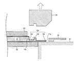
図3に示すように、可動上側パッド23および熱刃24を、板材10に向けて下方向に移動させる。そして、可動下側パッド22と可動上側パッド23とによって板材10を挟んで固定しつつ、熱刃24によって板材10の端部を厚さ方向に加熱押圧する。これにより、板材10の端部に薄肉部(図4における10aに相当。)が形成される。なお、板材10の厚さ方向は、図3における上下方向に相当する。以下の説明においても同様である。
図4に示すように、板材10を固定した状態を維持しつつ、熱刃24を上方向に移動させる。熱刃24によって形成された薄肉部10aは、板材10の外周側の端部(外周端)10bと、板材10の内部側の端部(内部端)10cと、内部端10cの周辺の被押圧面(薄肉部10aの上方向の面)に形成された凹部10dと、を有している。薄肉部10aは、内部端10cにて板材10の本体部10eと接続されている。即ち、薄肉部10aは、板材10の本体部10eから板材10の外周(端面11a)に向かう方向に伸びるようになっている。
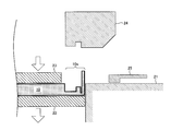
図5に示すように、板材10を可動下側パッド22と可動上側パッド23とによって挟んだ状態を維持しながら、可動下側パッド22および可動上側パッド23を下方向に移動させる。このとき、固定下側パッド21は、移動しない。これにより、薄肉部10aが、可動下側パッド22および可動上側パッド23と共に下方向に移動しながら、固定下側パッド21によって上方向に折り曲げられる。
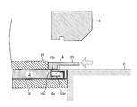
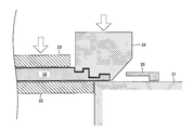
図6に示すように、板材10を固定した状態を維持しつつ、スライドカム25を左方向に移動させる。これにより、薄肉部がスライドカム25によって左方向に更に折り曲げられ、薄肉部の外周端10bが本体部10eの近傍へ(別の言い方をすると、内部端10cの近傍へ)移動する。このように、手順4及び手順5により、薄肉部10a(図2を参照。)は被押圧面が内側になるように折り畳まれる。このとき、薄肉部10aの外周端10bの近く(例えば、外周端10bと内部端10cとの間)に、凹部10dによって形成される空隙Aが存在することになる。
図7に示すように、板材10を固定した状態を維持しつつ、スライドカム25を下方向に移動させる。即ち、移動不能に固定された板材10に対し、スライドカム25が押し付けられる。
上記手順1~6に従って処理された後の板材10(即ち、本実施形態に係る第1板材)が、装置20から取り外される。なお、取り外しの態様については、図示を省略する。
次に、本発明の第2実施形態について説明する。
第2実施形態と第1実施形態との主な相違点は、折り畳まれた薄肉部の外周端を押圧する手順(上述した手順6)において、(1)薄肉部の外周端を含む薄肉部の全体が押圧される点、及び、(2)スライドカムを移動不能に固定すると共に薄肉部をスライドカムに押し付ける点である。
図9に示すように、固定下側パッド31および可動下側パッド32が構成する平面上に、板材10を配置する。
図10に示すように、可動上側パッド33を下方向に移動させて板材10を固定しつつ、熱刃34を下方向に移動させて板材10の端部を厚さ方向に加熱押圧する。これにより、板材10の端部に薄肉部(図11における10aに相当。)が形成される。
図11に示すように、熱刃34を上方向に移動させる。薄肉部10aは、板材10の外周側の端部(外周端)10bと、板材10の内部側の端部(内部端)10cと、内部端10cの周辺の被押圧面に形成された凹部10dと、を有している。
図12に示すように、板材10を可動下側パッド32と可動上側パッド33とによって挟んだ状態を維持しながら、可動下側パッド32および可動上側パッド33を下方向に移動させる。これにより、薄肉部10aが上方向に折り曲げられる。
図13に示すように、板材10を固定した状態を維持しつつ、スライドカム35を左方向に移動させる。このとき、スライドカム35の先端部(左方向の端部)は、薄肉部の外周端10bだけでなく、本体部10eのうちの外周端10bの周辺に存在する部分を覆う位置にまで進む。これにより、薄肉部がスライドカム35によって左方向に更に折り曲げられ、薄肉部の外周端10bが本体部10eの近傍へ(別の言い方をすると、内部端10cの近傍へ)移動する。
図14に示すように、スライドカム35を固定し、板材10を可動下側パッド32と可動上側パッド33とによって挟んだ状態を維持しながら、可動下側パッド32および可動上側パッド33を上方向に移動させる。即ち、移動不能に固定されたスライドカム35に対し、板材10が押し付けられる。
上記手順1~6に従って処理された後の板材10(即ち、本実施形態に係る第2板材)が、装置30から取り外される。
上記実施形態(第1実施形態及び第2実施形態)に係る「板材端部の処理方法」は、熱可塑性樹脂から構成される板材10の端部(切断面11a)を処理する際に用いられる。
板材10の端部を厚さ方向に加熱押圧して薄肉部10aを形成する第1工程(手順2,3)と、
薄肉部10aを被押圧面が内側になるように折り畳み、薄肉部10aの板材外周側の端部である外周端10bを、薄肉部10aの板材内部側の端部である内部端10cが接続された板材10の本体部10eの近傍へ移動させる第2工程(手順4,5)と、
薄肉部の外周端10bを厚さ方向に押圧して本体部の表面10fよりも厚さ方向の内側に移動させる第3工程(手順6)と、
を含んでいる。
板材10を所定の形状に切断する工程(図1を参照。)と、
板材10の端部を厚さ方向に加熱押圧して薄肉部10aを形成する第1処理(手順2,3)と、薄肉部10aを被押圧面が内側になるように折り畳み、薄肉部10aの板材10外周側の端部である外周端10bを、薄肉部10aの板材10内部側の端部である内部端10cが接続された板材10の本体部10eの近傍へ移動させる第2処理(手順4,5)と、薄肉部の外周端10bを厚さ方向に押圧して本体部の表面10fよりも厚さ方向の内側に移動させる第3処理(手順6)と、を含む工程と、を含む。
板材10の端部を処理する装置20,30であって、
板材の端部を厚さ方向に加熱押圧して薄肉部10aを形成する第1機構(例えば、熱刃24)と、薄肉部10aを被押圧面が内側になるように折り畳み、薄肉部10aの板材外周側の端部である外周端10bを、薄肉部10aの板材内部側の端部である内部端10cが接続された板材の本体部10eの近傍へ移動させる第2機構(例えば、固定下側パッド21、可動下側パッド22および可動上側パッド23)と、薄肉部の外周端10bを厚さ方向に押圧して本体部の表面10fよりも厚さ方向の内側に移動させる第3機構(例えば、スライドカム25)と、を備えている。
端部処理構造が、板材10の本体部分10eと、本体部分10eから伸びる薄肉部10aが湾曲した部分と、を有する構造であって、薄肉部10aの先端部(外周端10b)が本体部分10eの近傍へ移動するように薄肉部10aが湾曲していると共に、薄肉部10aの先端部10bが本体部の表面10fよりも厚さ方向の内側に移動しているように、構成されている。
本発明は上記実施形態に限定されることはなく、本発明の範囲内において種々の変形例を採用することができる。
Claims (21)
- 熱可塑性樹脂から構成される板材の端部の処理方法であって、
前記板材の端部を厚さ方向に加熱押圧して薄肉部を形成する第1工程と、
前記薄肉部を被押圧面が内側になるように折り畳み、前記薄肉部の板材外周側の端部である外周端を、前記薄肉部の板材内部側の端部である内部端が接続された前記板材の本体部の近傍へ移動させる第2工程と、
前記薄肉部の外周端を厚さ方向に押圧して前記本体部の表面よりも厚さ方向の内側に移動させる第3工程と、
を含む、板材の端部の処理方法。 - 請求項1に記載の処理方法において、
前記第1工程にて、前記被押圧面が前記薄肉部の内部端の周辺において凹部を有するように前記薄肉部を形成する、板材の端部の処理方法。 - 請求項1又は請求項2に記載の処理方法において、
前記第3工程にて、前記薄肉部の外周端と併せて前記本体部のうちの前記薄肉部の外周端の周辺に存在する部分を厚さ方向に押圧する、板材の端部の処理方法。 - 請求項1~請求項3の何れか一項に記載の処理方法において、
前記第3工程にて、前記薄肉部の外周端が前記板材の内部に埋没した凹部が形成される、板材の端部の処理方法。 - 請求項1~請求項3の何れか一項に記載の処理方法において、
前記第3工程にて、前記薄肉部の外周端を含む前記薄肉部の全体が厚さ方向に押圧される、板材の端部の処理方法。 - 請求項1~請求項5のいずれか一項に記載の処理方法において、
前記板材の主面の双方に緩衝層が設けられている、板材の端部の処理方法。 - 熱可塑性樹脂から構成される板材の製造方法であって、
前記板材を所定の形状に切断する工程と、
前記板材の端部を厚さ方向に加熱押圧して薄肉部を形成する第1処理と、前記薄肉部を被押圧面が内側になるように折り畳み、前記薄肉部の板材外周側の端部である外周端を、前記薄肉部の板材内部側の端部である内部端が接続された前記板材の本体部の近傍へ移動させる第2処理と、前記薄肉部の外周端を厚さ方向に押圧して前記本体部の表面よりも厚さ方向の内側に移動させる第3処理と、を含む工程と、
を含む、板材の製造方法。 - 請求項7に記載の製造方法において、
前記第1処理にて、前記被押圧面が前記薄肉部の内部端の周辺において凹部を有するように前記薄肉部を形成する、板材の製造方法。 - 請求項7又は請求項8に記載の製造方法において、
前記第3処理にて、前記薄肉部の外周端と併せて前記本体部のうちの前記薄肉部の外周端の周辺に存在する部分を厚さ方向に押圧する、板材の製造方法。 - 請求項7~請求項9の何れか一項に記載の製造方法において、
前記第3処理にて、前記薄肉部の外周端が前記板材の内部に埋没した凹部が形成される、板材の製造方法。 - 請求項7~請求項9の何れか一項に記載の製造方法において、
前記第3処理にて、前記薄肉部の外周端を含む前記薄肉部の全体が厚さ方向に押圧される、板材の製造方法。 - 請求項5~請求項11のいずれか一項に記載の製造方法において、
前記板材の主面の双方に緩衝層が設けられている、板材の製造方法。 - 熱可塑性樹脂から構成される板材の端部を処理する装置であって、
前記板材の端部を厚さ方向に加熱押圧して薄肉部を形成する第1機構と、
前記薄肉部を被押圧面が内側になるように折り畳み、前記薄肉部の板材外周側の端部である外周端を、前記薄肉部の板材内部側の端部である内部端が接続された前記板材の本体部の近傍へ移動させる第2機構と、
前記薄肉部の外周端を厚さ方向に押圧して前記本体部の表面よりも厚さ方向の内側に移動させる第3機構と、
を備えた、板材の端部の処理装置。 - 請求項13に記載の処理装置において、
前記第1機構が、前記被押圧面が前記薄肉部の内部端の周辺において凹部を有するように前記薄肉部を形成する、板材の端部の処理装置。 - 請求項13又は請求項14に記載の処理装置において、
前記第3機構が、前記薄肉部の外周端と併せて前記本体部のうちの前記薄肉部の外周端の周辺に存在する部分を厚さ方向に押圧する、板材の端部の処理装置。 - 請求項13~請求項15の何れか一項に記載の処理装置において、
前記第3機構が、前記薄肉部の外周端が前記板材の内部に埋没した凹部を形成する、板材の端部の処理装置。 - 請求項13~請求項15の何れか一項に記載の処理装置において、
前記第3機構が、前記薄肉部の外周端を含む前記薄肉部の全体を厚さ方向に押圧する、板材の端部の処理装置。 - 請求項13~請求項17のいずれか一項に記載の装置において、
前記板材の主面の双方に緩衝層が設けられている、板材の端部の処理装置。 - 熱可塑性樹脂から構成され、端部が処理された端部処理構造を備える板材であって、
前記端部処理構造が、
前記板材の本体部分と、前記本体部分から伸びる薄肉部が湾曲した部分と、を有する構造であって、前記薄肉部の先端部が前記本体部分の近傍へ移動するように前記薄肉部が湾曲していると共に、前記薄肉部の先端部が前記本体部の表面よりも厚さ方向の内側に移動している構造である、
板材。 - 請求項19に記載の板材において、
前記端部処理構造が、前記本体部分のうちの前記薄肉部の先端部の周辺に存在する部分が前記薄肉部の先端部と併せて前記本体部の表面よりも厚さ方向の内側に移動している構造である、板材。 - 請求項19又は請求項20に記載の板材において、
前記板材の主面の双方に緩衝層が設けられている、板材。
Priority Applications (3)
| Application Number | Priority Date | Filing Date | Title |
|---|---|---|---|
| US14/900,479 US10207459B2 (en) | 2013-06-21 | 2014-06-20 | Working method for end portion of plate member, manufacturing method for plate member, working apparatus for end portion of plate member, and plate member |
| JP2015522991A JP5997380B2 (ja) | 2013-06-21 | 2014-06-20 | 板材の端部の処理方法、板材の製造方法、板材の端部の処理装置、及び、板材 |
| CN201480035526.1A CN105408087B (zh) | 2013-06-21 | 2014-06-20 | 板材的端部的处理方法、板材的制造方法、板材的端部的处理装置以及板材 |
Applications Claiming Priority (2)
| Application Number | Priority Date | Filing Date | Title |
|---|---|---|---|
| JP2013130678 | 2013-06-21 | ||
| JP2013-130678 | 2013-06-21 |
Publications (1)
| Publication Number | Publication Date |
|---|---|
| WO2014203992A1 true WO2014203992A1 (ja) | 2014-12-24 |
Family
ID=52104718
Family Applications (1)
| Application Number | Title | Priority Date | Filing Date |
|---|---|---|---|
| PCT/JP2014/066418 Ceased WO2014203992A1 (ja) | 2013-06-21 | 2014-06-20 | 板材の端部の処理方法、板材の製造方法、板材の端部の処理装置、及び、板材 |
Country Status (4)
| Country | Link |
|---|---|
| US (1) | US10207459B2 (ja) |
| JP (1) | JP5997380B2 (ja) |
| CN (1) | CN105408087B (ja) |
| WO (1) | WO2014203992A1 (ja) |
Citations (10)
| Publication number | Priority date | Publication date | Assignee | Title |
|---|---|---|---|---|
| JPS53137274A (en) * | 1977-05-06 | 1978-11-30 | Mitsui Petrochem Ind Ltd | Processing of the end of laminated plate |
| JPS6015059U (ja) * | 1983-07-12 | 1985-02-01 | 林テレンプ株式会社 | 成形天井内装材の端末構造 |
| JPS63165119A (ja) * | 1986-12-26 | 1988-07-08 | Toyo Tire & Rubber Co Ltd | 表皮層張込み内装品の製造方法 |
| JPH01118432A (ja) * | 1987-11-02 | 1989-05-10 | Jsp Corp | 自動車用天井材の製造方法 |
| JPH1059085A (ja) * | 1996-08-22 | 1998-03-03 | Hino Motors Ltd | 自動車用内張り部材 |
| JPH10166438A (ja) * | 1996-12-16 | 1998-06-23 | Kasai Kogyo Co Ltd | 積層材の端末処理方法 |
| JPH10291248A (ja) * | 1997-04-18 | 1998-11-04 | Kasai Kogyo Co Ltd | 積層材の端末処理装置とその端末処理方法 |
| JP2001219793A (ja) * | 2000-02-09 | 2001-08-14 | Fuji Heavy Ind Ltd | 振動遮断防音材 |
| JP2006123322A (ja) * | 2004-10-28 | 2006-05-18 | Kasai Kogyo Co Ltd | 自動車用内装部品及びその製造方法 |
| JP2008222255A (ja) * | 2007-03-09 | 2008-09-25 | Tokan Kogyo Co Ltd | 中空合成樹脂板を用いた函体およびその製造方法 |
Family Cites Families (5)
| Publication number | Priority date | Publication date | Assignee | Title |
|---|---|---|---|---|
| US6161895A (en) * | 1998-02-27 | 2000-12-19 | Lear Automotive Dearborn, Inc. | Pleated corners for vehicle trim openings |
| JP3878347B2 (ja) | 1998-12-25 | 2007-02-07 | 東罐興業株式会社 | 中空体合成樹脂板の端面処理方法及びその装置 |
| CN102681334B (zh) * | 2007-07-06 | 2015-09-30 | 旭化成电子材料株式会社 | 从容纳容器取出大型表膜构件的取出方法 |
| US7874832B2 (en) * | 2008-06-13 | 2011-01-25 | Kimastle Corporation | Assembly for producing an auto headliner with a folded-over perimeter edge |
| ES2548478T3 (es) * | 2010-12-27 | 2015-10-16 | Grupo Antolín-Ingeniería, S.A. | Guarnecido de techo para vehículos con un perímetro acabado |
-
2014
- 2014-06-20 WO PCT/JP2014/066418 patent/WO2014203992A1/ja not_active Ceased
- 2014-06-20 JP JP2015522991A patent/JP5997380B2/ja active Active
- 2014-06-20 CN CN201480035526.1A patent/CN105408087B/zh not_active Expired - Fee Related
- 2014-06-20 US US14/900,479 patent/US10207459B2/en not_active Expired - Fee Related
Patent Citations (10)
| Publication number | Priority date | Publication date | Assignee | Title |
|---|---|---|---|---|
| JPS53137274A (en) * | 1977-05-06 | 1978-11-30 | Mitsui Petrochem Ind Ltd | Processing of the end of laminated plate |
| JPS6015059U (ja) * | 1983-07-12 | 1985-02-01 | 林テレンプ株式会社 | 成形天井内装材の端末構造 |
| JPS63165119A (ja) * | 1986-12-26 | 1988-07-08 | Toyo Tire & Rubber Co Ltd | 表皮層張込み内装品の製造方法 |
| JPH01118432A (ja) * | 1987-11-02 | 1989-05-10 | Jsp Corp | 自動車用天井材の製造方法 |
| JPH1059085A (ja) * | 1996-08-22 | 1998-03-03 | Hino Motors Ltd | 自動車用内張り部材 |
| JPH10166438A (ja) * | 1996-12-16 | 1998-06-23 | Kasai Kogyo Co Ltd | 積層材の端末処理方法 |
| JPH10291248A (ja) * | 1997-04-18 | 1998-11-04 | Kasai Kogyo Co Ltd | 積層材の端末処理装置とその端末処理方法 |
| JP2001219793A (ja) * | 2000-02-09 | 2001-08-14 | Fuji Heavy Ind Ltd | 振動遮断防音材 |
| JP2006123322A (ja) * | 2004-10-28 | 2006-05-18 | Kasai Kogyo Co Ltd | 自動車用内装部品及びその製造方法 |
| JP2008222255A (ja) * | 2007-03-09 | 2008-09-25 | Tokan Kogyo Co Ltd | 中空合成樹脂板を用いた函体およびその製造方法 |
Also Published As
| Publication number | Publication date |
|---|---|
| CN105408087B (zh) | 2017-05-31 |
| CN105408087A (zh) | 2016-03-16 |
| JPWO2014203992A1 (ja) | 2017-02-23 |
| US10207459B2 (en) | 2019-02-19 |
| US20160151967A1 (en) | 2016-06-02 |
| JP5997380B2 (ja) | 2016-09-28 |
Similar Documents
| Publication | Publication Date | Title |
|---|---|---|
| EP3085528A1 (en) | Touch panel and method of its manufacturing | |
| CN111867747A (zh) | 冲压成型用的金属板、冲压成型装置和冲压部件的制造方法 | |
| JP2017011799A (ja) | 輻射熱遮蔽コルゲートチューブ形成用シートおよびワイヤハーネス | |
| JP5997380B2 (ja) | 板材の端部の処理方法、板材の製造方法、板材の端部の処理装置、及び、板材 | |
| WO2015149137A1 (en) | Visor assembly | |
| JP6914035B2 (ja) | シート状積層体の製造方法、シート状積層体を成形する金型、及びシート状積層体 | |
| WO2012049878A1 (ja) | 樹脂積層ボード部材及びその端末処理方法 | |
| JP6472882B2 (ja) | バーリング加工方法及びバーリング加工システム | |
| CN110709221B (zh) | 发泡成型方法、发泡成型品及其制造方法 | |
| WO2026026226A1 (zh) | 一种方向盘及机动车辆 | |
| US9498812B2 (en) | Die for reducing springback and process thereof | |
| JP5557374B2 (ja) | プレス成形金型 | |
| KR101369085B1 (ko) | 알루미늄 복합판넬의 절단면 처리방법 및, 이에 의해 제조된 알루미늄 복합판넬 | |
| JP6185365B2 (ja) | 車両用内装材 | |
| JP4168930B2 (ja) | ロール成形装置及びロール成形方法 | |
| CN115703250A (zh) | 用于制造包括实木片材的车辆用防撞垫的木材预成形装置 | |
| JP5633922B2 (ja) | 多層発泡基材及びその製造方法 | |
| JP2013090508A5 (ja) | ||
| JP5565800B2 (ja) | 車両用内装部品及びその製造方法 | |
| JP5633924B2 (ja) | 車両用内装部品及びその製造方法 | |
| JP6859853B2 (ja) | 凹凸材の製造方法 | |
| JP2005297307A (ja) | 表皮付発泡体の製造方法とインストルメントパネルの製造方法と成形型 | |
| JP2015139818A (ja) | プレス成形金型 | |
| JP7656563B2 (ja) | 補強部材の製造方法及び補強部材を用いたクッション体の製造方法 | |
| JP2015205447A (ja) | 発泡成形品 |
Legal Events
| Date | Code | Title | Description |
|---|---|---|---|
| WWE | Wipo information: entry into national phase |
Ref document number: 201480035526.1 Country of ref document: CN |
|
| 121 | Ep: the epo has been informed by wipo that ep was designated in this application |
Ref document number: 14814567 Country of ref document: EP Kind code of ref document: A1 |
|
| DPE1 | Request for preliminary examination filed after expiration of 19th month from priority date (pct application filed from 20040101) | ||
| ENP | Entry into the national phase |
Ref document number: 2015522991 Country of ref document: JP Kind code of ref document: A |
|
| NENP | Non-entry into the national phase |
Ref country code: DE |
|
| WWE | Wipo information: entry into national phase |
Ref document number: 14900479 Country of ref document: US |
|
| 122 | Ep: pct application non-entry in european phase |
Ref document number: 14814567 Country of ref document: EP Kind code of ref document: A1 |