WO2014199895A1 - 角膜内皮細胞撮影装置 - Google Patents
角膜内皮細胞撮影装置 Download PDFInfo
- Publication number
- WO2014199895A1 WO2014199895A1 PCT/JP2014/064962 JP2014064962W WO2014199895A1 WO 2014199895 A1 WO2014199895 A1 WO 2014199895A1 JP 2014064962 W JP2014064962 W JP 2014064962W WO 2014199895 A1 WO2014199895 A1 WO 2014199895A1
- Authority
- WO
- WIPO (PCT)
- Prior art keywords
- endothelial cell
- corneal endothelial
- imaging
- optical system
- eye
- Prior art date
- Legal status (The legal status is an assumption and is not a legal conclusion. Google has not performed a legal analysis and makes no representation as to the accuracy of the status listed.)
- Ceased
Links
Images














Classifications
-
- A—HUMAN NECESSITIES
- A61—MEDICAL OR VETERINARY SCIENCE; HYGIENE
- A61B—DIAGNOSIS; SURGERY; IDENTIFICATION
- A61B3/00—Apparatus for testing the eyes; Instruments for examining the eyes
- A61B3/10—Objective types, i.e. instruments for examining the eyes independent of the patients' perceptions or reactions
- A61B3/107—Objective types, i.e. instruments for examining the eyes independent of the patients' perceptions or reactions for determining the shape or measuring the curvature of the cornea
-
- A—HUMAN NECESSITIES
- A61—MEDICAL OR VETERINARY SCIENCE; HYGIENE
- A61B—DIAGNOSIS; SURGERY; IDENTIFICATION
- A61B3/00—Apparatus for testing the eyes; Instruments for examining the eyes
- A61B3/0075—Apparatus for testing the eyes; Instruments for examining the eyes provided with adjusting devices, e.g. operated by control lever
-
- A—HUMAN NECESSITIES
- A61—MEDICAL OR VETERINARY SCIENCE; HYGIENE
- A61B—DIAGNOSIS; SURGERY; IDENTIFICATION
- A61B3/00—Apparatus for testing the eyes; Instruments for examining the eyes
- A61B3/10—Objective types, i.e. instruments for examining the eyes independent of the patients' perceptions or reactions
- A61B3/14—Arrangements specially adapted for eye photography
Definitions
- the present invention relates to a corneal endothelial cell imaging apparatus for imaging corneal endothelial cells.
- a slit light illumination optical system for irradiating slit light obliquely toward the cornea of an eye to be examined, and observation photographing for observing and photographing a corneal endothelial cell image using reflected light from the cornea
- a corneal endothelial cell imaging device including an optical system is known (see Patent Document 1).
- the corneal endothelial cell of the eye to be examined is photographed by the corneal endothelial cell photographing optical system while fixing the line of sight of the eye to be examined in a desired direction from a fixed viewpoint, and thus the corneal endothelial cell of the eye to be examined is arbitrarily selected. Can be taken.
- the fixation point can define the position of the corneal endothelial cell of the eye to be imaged by the corneal endothelial cell imaging optical system by fixing the line of sight of the eye to be examined in an arbitrary direction.
- the corneal endothelial cell imaging device if the number of positions that can be imaged in the corneal endothelial cells and the number thereof are increased, the management of which positions are imaged becomes complicated, and the operation for performing the operations is complicated. There is a possibility that it will become a thing. This becomes remarkable when there are more than six positions that can be imaged in corneal endothelial cells. For this reason, the room for improvement arises from a viewpoint of improving usability.
- the present invention has been made in view of the above circumstances.
- Corneal endothelial cell imaging capable of improving usability even when a plurality of imaging positions in the corneal endothelial cell of the eye to be imaged are set.
- An object is to provide an apparatus.
- a corneal endothelial cell imaging device includes a slit light irradiation optical system that irradiates slit light toward the cornea of an eye to be examined, and reflection of the cornea from corneal endothelial cells.
- a corneal endothelial cell imaging optical system that receives light and images the corneal endothelial cell, and images the corneal endothelial cell of the eye to be examined by the corneal endothelial cell imaging optical system.
- a plurality of fixation points for fixing the line of sight of the subject's eye in an arbitrary direction to define a position, and forming each of the fixation points, and operations of the slit light irradiation optical system and the corneal endothelial cell imaging optical system A plurality of imaging positions in the corneal endothelial cell that are imaged by the corneal endothelial cell imaging optical system, and the control unit is configured to control the set imaging position. Performing the photographing operation of the corneal endothelial cell by the slit light irradiation optical system and the corneal endothelial cell photographing optical system while forming the fixed viewpoint to be performed on all the photographing positions set. It is characterized by.
- the corneal endothelial cell imaging device of the present invention usability can be improved even when a plurality of imaging positions in the corneal endothelial cells of the eye to be imaged are set.
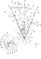
- FIG. 1 is an optical layout diagram showing an optical system of a corneal endothelial cell imaging device 10.
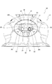
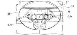
- FIG. It is explanatory drawing which shows a mode that the periphery of the opposing position 17 in the apparatus main body part 13 of the corneal-endothelial-cells imaging device 10 was seen in front.
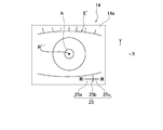
- FIG. 4 is an explanatory diagram showing a state in which an anterior segment image E ′ of a subject eye E is displayed on the display surface 14a of the display unit 14.
- FIG. FIG. 4 is an explanatory diagram shown in a schematic perspective view for explaining the configuration of an internal fixation point projection optical system. It is explanatory drawing which shows a mode that the fixation point was formed by the external periphery fixation light source 32 and the internal fixation point projection optical system 38 in the opposing position 17 of the apparatus main body part 13, and the center fixation point fc is formed in the objective window 33h. Show the state.
- FIG. 4 is an explanatory diagram showing a state in which an anterior segment image E ′ of a subject eye E is displayed on the display surface 14a of the display unit 14.
- FIG. FIG. 4 is an explanatory diagram shown in a schematic perspective view for explaining the configuration of an internal fixation point projection optical system. It is explanatory drawing which shows a mode that the fixation point was formed by the external periphery fixation
- FIG. 10 is an explanatory view showing a state in which a fixation point is formed by an external peripheral fixation light source 32 and an internal fixation point projection optical system 38 at a facing position 17 of the apparatus main body 13, and there are eight inner peripheral fixation points fi in the objective window 33h. It shows how it is formed.
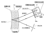
- FIG. 10 is an explanatory view showing a state in which a fixation point is formed by an external peripheral fixation light source 32 and an internal fixation point projection optical system 38 at a facing position 17 of the apparatus main body 13, and there are six outer peripheral fixation points outside the objective window 33h. A mode that the viewpoint fo is formed is shown. It is explanatory drawing which shows the reflective state of the slit light beam in the cornea Ec of the eye E to be examined.
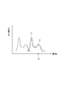
- FIG. 5 is a graph showing the intensity distribution of the amount of light received by the image sensor 33g when the alignment is deviated, and is an explanatory diagram showing the positional relationship between the liquid crystal shutter and the image sensor 33g in correspondence with the graph.
- FIG. It is explanatory drawing which shows a mode that the corneal-endothelial-cell image J of corneal-endothelial-cell S2c is displayed on the display surface 14a of the display part 14.
- FIG. It is explanatory drawing which shows the imaging
- FIG. 7 is an explanatory diagram for explaining display contents of a shooting type setting screen Sk displayed on the display surface 14a of the display unit 14.
- FIG. 7 is explanatory drawing for demonstrating the display content of the imaging
- FIG. 7 is an explanatory diagram for explaining display contents of an anterior ocular segment observation screen So displayed on the display surface 14a of the display unit 14.
- FIG. 10 is an explanatory diagram for explaining display contents of a photographing result screen Sr displayed on the display surface 14a of the display unit 14; It is explanatory drawing for demonstrating the display content of the measurement status indication symbol.
- 4 is a flowchart showing display control processing executed by a control unit 21.
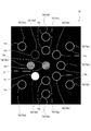
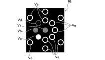
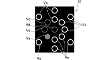
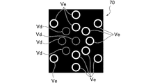
- FIG. 3 is a flowchart showing a continuous acquisition control process executed by a control unit 21. It is explanatory drawing for demonstrating the aspect of the change of the display content in the measurement status indication symbol 70, and shows the state before imaging
- a corneal endothelial cell imaging device 10 as an embodiment of a corneal endothelial cell imaging device according to the present invention will be described with reference to FIGS.
- the corneal endothelial cell photographing apparatus 10 photographs corneal endothelial cells S2c (see FIG. 10 and the like) of the eye E (see FIG. 4 and the like).
- the cornea (anterior eye portion) Ec and the corneal apex Ep are schematically shown in each figure.
- FIG. 10 and 11 show a boundary surface (corneal epidermis) S1 with the air in the cornea (anterior eye portion) Ec, a corneal endothelium S2, and a corneal stroma S3.
- FIG. 4 for easy understanding, two illumination light beams and two reflected light beams are shown in parallel in each optical path in the optical system of the corneal endothelial cell photographing apparatus 10. It travels on the optical axis (O1, O2, O3) and does not necessarily coincide with the actual scene.
- This corneal endothelial cell imaging device 10 is configured such that a device main body 13 is movably provided on a base 11 via a drive unit 12 (see FIG. 3).
- the device main body 13 is provided with an optical system (see FIG. 4) of the corneal endothelial cell imaging device 10 described later on the inside, and a display unit 14, a chin rest 15 and a forehead portion 16 are provided on the outside. ing.
- the display unit 14 is formed of a liquid crystal display, and under the control of a control unit 21 (see FIG. 3), which will be described later, is an image of an anterior segment image E ′ of the eye E (see FIG. 7 and the like) and the corneal endothelium.
- a cell image J (see FIG. 15 and the like), various operation screens (see FIGS. 18 to 20 and the like), a measurement result (see FIG. 21 and the like), a measurement state indication symbol 70 (see FIG. 22 and the like), and the like are displayed.
- the display unit 14 has a touch panel function, and performs an operation for photographing the corneal endothelial cell S2c (see FIG. 10 and the like), an operation for moving the apparatus main body unit 13, and a cornea.
- the display unit 14 displays various symbols (reference numerals 51 to 55 (see FIGS. 18 to 21, etc.)) as icons for operations in each measurement mode to be described later, using the function of the touch panel. However, it is possible to operate by touching each symbol.
- the operation for performing the measurement may be performed by providing a measurement switch and operating the measurement switch.
- an operation for moving the apparatus main body 13 may be performed by providing a control lever or a movement operation switch and operating the control lever or the movement operation switch.
- the chin rest 15 and the forehead support 16 fix the face of the subject (patient), that is, the position of the eye E to be measured with respect to the apparatus main body 13, and are fixed to the base 11. ing.
- the jaw holder 15 is a place where the subject places his / her chin
- the forehead holder 16 is a place where the subject places the forehead.
- the eye E of the subject faces the facing position 17 (see FIG. 1).
- an objective window 33h described later, an objective window 34k described later, and an objective window 35i described later are provided at the facing position 17 (see FIG. 1).
- the eye E can be measured by the system.
- the display unit 14, the chin rest 15 and the forehead support 16 are provided on both sides of the device main body 13, and in normal use (see FIG. 2).
- the display unit 14 (the display surface 14a) is on the examiner side, and the chin rest 15 and the forehead support unit 16 are on the subject side.
- the display unit 14 is rotatably supported by the apparatus main body unit 13 to change the orientation of the display surface 14a, for example, to direct the display surface 14a toward the subject (see the two-dot chain line in FIG. 1).
- the display unit 14 (refer to the display surface 14a) shown in FIG. 2) and the display surface 14a can be directed to the side (X-axis direction).
- the control part 21 (refer FIG.
- the apparatus main body 13 is moved with respect to the base 11 by the drive unit 12, that is, is moved with respect to the eye E (face of the subject) fixed by the chin rest 15 and the forehead support 16. It is possible to do.
- the drive unit 12 has a vertical direction (Y-axis direction) and a front-rear direction (Z-axis direction (a direction orthogonal to the display surface 14a of the display unit 14 during normal use)) with respect to the base 11 with respect to the apparatus main body 13. And a left-right direction (X-axis direction) perpendicular to them.
- the upper side in the vertical direction is the positive side in the Y-axis direction
- the subject side in the front-rear direction (the left front side when viewed from the front in FIG. 1) is the positive side in the Z-axis direction.
- the right front side is the positive side in the X-axis direction (see the arrow in FIG. 1).
- the drive unit 12 includes an X motor 12a, a Y motor 12b, and a Z motor 12c, and an X driver 12d, a Y driver 12e, and a Z driver 12f for driving each of them. And have.
- the X motor 12 a moves (displaces) the apparatus main body 13 in the X axis direction (left and right direction) with respect to the base 11.
- the X motor 12a is configured to move the apparatus main body 13 in the X-axis direction (left-right direction) in the drive unit 12.
- the X motor 12a is appropriately driven when the control unit 21 controls the X driver 12d.
- the Y motor 12b moves (displaces) the device main body 13 in the Y axis direction (vertical direction) with respect to the base 11.
- the Y motor 12b is a location for moving the apparatus main body 13 in the Y-axis direction (vertical direction) in the drive unit 12.
- the Y motor 12b is appropriately driven by controlling the Y driver 12e by the control unit 21.
- the Z motor 12c moves (displaces) the apparatus main body 13 in the Z-axis direction (front-rear direction) with respect to the base 11.
- the Z motor 12 c is a location for moving the apparatus main body 13 in the Z-axis direction (front-rear direction) in the drive unit 12.
- the Z motor 12c is appropriately driven when the control unit 21 controls the Z driver 12f.
- the drive unit 12 appropriately drives the X motor 12a, the Y motor 12b, and the Z motor 12c to move the apparatus main body unit 13 in the vertical direction (Y-axis direction) and the front-rear direction (Z-axis direction). Direction) and right and left direction (X-axis direction).
- the control unit 21 appropriately controls the drive unit 12, that is, appropriately drives the X motor 12a, the Y motor 12b, and the Z motor 12c via the X driver 12d, the Y driver 12e, and the Z driver 12f.
- the apparatus main body 13 can be appropriately moved with respect to the chin rest 15 and the forehead support 16 fixed to the base 11.
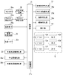
- the control unit 21 constitutes an electric control system in the corneal endothelial cell imaging device 10 and controls each part of the corneal endothelial cell imaging device 10 in a centralized manner by a program stored in the built-in storage unit 21a. As will be described later, the control unit 21 appropriately controls the drive unit 12 based on the focus signal from the focus determination circuit 22 and the shift amount signal from the alignment determination circuit 23 to control the apparatus main body 13 with respect to the base 11. Adjust the position. Moreover, the control part 21 displays the image on the display part 14 (the display surface 14a) based on the image which the image sensor 33g of the anterior ocular segment observation optical system 33 (refer FIG. 4) mentioned later acquires.
- control unit 21 includes an anterior ocular segment illumination light source 31, an alignment index light source 36a, an imaging light source 34g, an observation light source 34c, each external peripheral fixation light source 32, a central fixation light source 38a, and each internal peripheral fixation. Each is connected to a light source 38b, and the light emission of each of these light sources is appropriately controlled.
- the apparatus main body 13 is also provided with the configuration of the optical system in the corneal endothelial cell photographing apparatus 10 inward as described above.
- the configuration of the optical system of the corneal endothelial cell imaging apparatus 10 will be described with reference to FIGS. 4 to 15 in addition to FIG.
- the corneal endothelial cell imaging device 10 includes an anterior segment illumination light source 31, an external peripheral fixation light source 32, an anterior segment observation optical system 33, and a cornea as an example of a slit light irradiation optical system.
- An endothelial cell illumination optical system 34 and a corneal endothelial cell imaging optical system 35 are provided.
- the anterior ocular segment illumination light source 31 is a light source for illuminating the anterior segment of the eye E to be examined. This anterior ocular segment illumination light source 31 is shown in FIG. As shown, a plurality (four in this embodiment) are provided outside the objective window 33h described later so as to surround the optical axis O1 of the anterior ocular segment observation optical system 33. Each anterior segment illumination light source 31 is lit to directly illuminate the anterior segment.
- the external peripheral fixation light source 32 is a light source for projecting (presenting) a fixed viewpoint on the eye E to be examined.
- a plurality of external peripheral fixation light sources 32 surround the optical axis O1 of the anterior ocular segment observation optical system 33 outside the objective window 33h, which will be described later, at the facing position 17 of the apparatus body 13. 6) provided.
- Each external peripheral fixation light source 32 is turned on to project a fixation point (see reference numeral fo in FIG. 9C) on the eye E and cause the subject to gaze as a fixation target. Fix your line of sight. Since each external peripheral fixation light source 32 is provided so as to surround the objective window 33h, each fixed viewpoint (center fixed viewpoint fc (see FIG.
- each external peripheral fixation light source 32 can form six outer peripheral fixation viewpoints fo at the outermost position (see FIG. 9C). From this, each external peripheral fixation light source 32 is directed to the outside of the objective window 33h of the anterior ocular segment observation optical system 33 by gazing at one outer peripheral fixation viewpoint fo formed by lighting one of them.
- the line of sight of the subject can be fixed at an arbitrary rotational position (in this example, any one of six) centered on the optical axis O1 at a position greatly deviated from the optical axis O1.
- each external peripheral fixation light source 32 is provided corresponding to each fixation point individually, and functions as an example fixation light source that is lit under the control of the control unit 21 to form a corresponding fixation point.
- Each outer peripheral fixation point fo formed by each external peripheral fixation light source 32 functions as an example fixation point for fixing the line of sight of the eye E to be examined in an arbitrary direction.
- These six outer peripheral fixed viewpoints fo are individually displayed in lower-case alphabetical characters (a to f) in the order of the counterclockwise direction from the upper right side in FIG. Attached is shown.
- the anterior ocular segment observation optical system 33 is provided for observing the anterior ocular segment of the eye E as shown in FIG.
- the anterior segment observation optical system 33 is provided with an alignment index projection optical system 36, an alignment detection optical system 37, and an internal fixation viewpoint projection optical system 38.
- the alignment index projection optical system 36 adjusts the position of the eye E (the anterior eye portion (cornea Ec)) in the XY direction with respect to the device main body 13 (the optical system of the corneal endothelial cell imaging device 10), so-called XY direction.
- An alignment index for detecting alignment is projected.
- the alignment detection optical system 37 adjusts the position of the eye E (the anterior eye portion (cornea Ec)) in the XY direction with respect to the apparatus main body 13 (the optical system of the corneal endothelial cell imaging device 10), that is, alignment in the so-called XY direction. It is to detect.
- the internal fixation point projection optical system 38 places a fixation point (a central fixation point fc (see FIG. 9A) and an inner peripheral fixation point fi (see FIG. 9B)) on the eye E to be examined on the optical path of the anterior ocular segment observation optical system 33. Project (present).
- the corneal endothelial cell illumination optical system (slit light irradiation optical system) 34 is provided to illuminate the corneal endothelium S2 of the eye E (the corneal endothelial cell S2c (see FIG. 10)).
- the corneal endothelial cell photographing optical system 35 is provided for photographing the corneal endothelial cell S2c of the corneal endothelium S2.
- the corneal endothelial cell imaging optical system 35 is provided with a focusing position detection optical system (Z alignment detection optical system) 39.
- the focusing position detection optical system 39 adjusts the position of the eye E (the anterior eye portion (cornea Ec)) in the Z direction with respect to the device main body 13 (the optical system of the corneal endothelial cell imaging device 10), the so-called Z direction.
- the alignment for detecting the alignment is detected.
- the anterior ocular segment observation optical system 33 includes, on the optical axis O1, a half mirror 33a, an objective lens 33b, a half mirror 33c, a diaphragm 33d, an imaging lens 33e, a light shielding plate 33f, an image sensor 33g, And an objective window 33h (see FIG. 5 and the like).
- the light shielding plate 33f reflects the reflected light (reflected light beam) of the illumination light (illuminated light beam) from the anterior segment illumination light source 31 reflected by the cornea Ec, and the alignment index light source 36a described later of the alignment index projection optical system 36.
- the illumination light is formed of a member that can block (shield) the reflected light (reflected light beam) reflected by the cornea Ec.
- the light shielding plate 33f can be present on the optical axis O1 and can be detached from the optical axis O1 by a moving mechanism (not shown).
- the moving mechanism is appropriately driven under the control of the control unit 21 (see FIG. 3) to displace the light shielding plate 33f as described above.
- This moving mechanism can be configured using, for example, a solenoid.
- the objective window 33h (see FIG. 5 and the like) is provided on the optical axis O1 at the facing position 17 that is the end of the apparatus main body 13 on the subject side in the front-rear direction (positive side in the Z-axis direction).
- the image sensor 33g is composed of a solid-state image sensor such as a CCD image sensor or a CMOS image sensor.
- the image sensor 33g converts a subject image formed on the light receiving surface into an electric signal (image data) and controls the control unit 21 (FIG. 3). Output).
- the reflected light beam from the cornea Ec of the illumination light from the anterior ocular segment illumination light source 31 is transmitted to the objective lens 33b through the objective window 33h (see FIG. 5 and the like) and the half mirror 33a.
- the reflected light beam is converged by the objective lens 33b, and a part of the reflected light beam is guided to the imaging lens 33e after passing through the half mirror 33c and the diaphragm 33d, and the imaging lens 33e
- An image is formed on the image sensor 33g.
- an anterior segment image of the eye E is formed on the image sensor 33g.
- the image sensor 33g outputs a light reception signal based on the reception of the formed reflected light beam (anterior eye image) to the control unit 21 (see FIG. 3).
- the alignment index projection optical system 36 provided in the anterior ocular segment observation optical system 33 includes an alignment index light source 36a, a projection lens 36b, a half mirror 36c, and a lens 36d, and the anterior segment observation optical system 33 and the half mirror. 33a and the objective window 33h (see FIG. 5 etc.) are shared.
- the alignment index light source 36a is a light source for forming an alignment index, that is, a light source that emits alignment index light (illumination light beam), and is a pinhole light source (point light source).
- the alignment index light source 36a is disposed at a focal position in the combination of the projection lens 36b and the lens 36d.
- the projection lens 36b and the lens 36d use the alignment index light emitted from the alignment index light source 36a as a parallel light beam.
- the half mirror 36c is provided on the optical axis O4, guides the alignment index light emitted from the alignment index light source 36a and passed through the projection lens 36b on the optical axis O4, and guides it to the half mirror 33a.
- the anterior segment observation is performed by reflecting the alignment index light on the optical axis O4, which is a parallel light beam between the projection lens 36b and the lens 36d, via the half mirror 36c, by the half mirror 33a. It advances on the optical axis O1 of the optical system 33.
- the alignment index light is guided to the cornea Ec of the eye E through the objective window 33h (see FIG. 5 and the like).
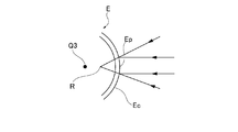
- the alignment index projection optical system 36 forms a virtual image R of the alignment index light at a substantially intermediate position between the corneal apex Ep and the corneal curvature center Q3 (see FIG. 6).
- the alignment detection optical system 37 includes an alignment detection sensor 37a, and shares the anterior ocular segment observation optical system 33, the half mirror 33a, the objective lens 33b, the half mirror 33c, and the objective window 33h (see FIG. 5 and the like).
- the alignment detection sensor 37a detects the position of the virtual image R (see FIG. 6) (image R ′ (not shown)) of the alignment index light formed by the alignment index projection optical system 36.
- This alignment detection sensor 37a is composed of a position sensor as position detection means, and in this embodiment, a two-dimensional PSD is used.
- the alignment detection sensor 37a is disposed at a position conjugate with the virtual image R (see FIG. 6) of the alignment index light with respect to the objective lens 33b.
- the reflected light (the light beam) of the alignment index light reflected by the cornea Ec travels on the optical axis O1 and passes through the objective window 33h (see FIG. 5 and the like). Then, the light passes through the objective lens 33b and advances to the half mirror 33c.
- the alignment detection optical system 37 a part of the reflected light beam of the alignment index light traveling on the optical axis O1 is reflected by the half mirror 33c and imaged on the alignment detection sensor 37a (image R of the virtual image R of the alignment index light). '(Not shown)).
- the alignment detection optical system 37 detects the light reception position of the image R ′ on the alignment detection sensor 37a based on the light reception signal of the image R ′ (not shown) by the alignment detection sensor 37a. Thereby, the alignment detection optical system 37 can detect the alignment index light with respect to the eye E, that is, the shift amount of the apparatus main body 13 in the XY directions (left and right directions and up and down directions).
- the reflected light beam from the cornea Ec of the illumination light from the anterior ocular segment illumination light source 31 is imaged on the image sensor 33g (the anterior segment image E ′ of the eye E to be examined).
- the other part of the reflected light beam of the alignment index light traveling on the optical axis O1 is transmitted through the half mirror 33c, thereby capturing an image R ′′ of the virtual image R of the alignment index light. It can be formed on the element 33g.
- the anterior ocular segment observation optical system 33 when the alignment of the eye E to be examined and the apparatus main body 13 (the optical system of the corneal endothelial cell imaging apparatus 10) is substantially aligned, a virtual image R by the virtual image R of the alignment index light. ′′ Is simultaneously formed on the image sensor 33 g together with the anterior segment image E ′ of the eye E to be examined.
- the image sensor 33g outputs a light reception signal based on reception of the formed reflected light beam to the control unit 21 (see FIG. 3).
- the control unit 21 causes the display unit 14 (the display surface 14a) to display an image based on the light reception signal from the image sensor 33g.
- the anterior ocular segment observation optical system 33 based on the light received by the image sensor 33g, the anterior ocular segment image E ′ of the eye E and the virtual image R ′′ of the alignment index light are displayed on the display surface 14a of the display unit 14. Are displayed simultaneously (see FIG. 7).
- the anterior ocular segment observation optical system 33 displays the annular pattern image A on the display surface 14a of the display unit 14 simultaneously with the anterior ocular segment image E ′ and the virtual image R ′′ (see FIG. 7).
- This annular pattern image A shows an allowable range of misalignment of the alignment index light with respect to the eye E, that is, the XY direction (left and right direction and up and down direction) of the apparatus main body 13. That is, the annular pattern image A indicates a range in which the position of the apparatus main body 13 in the XY direction with respect to the eye E is appropriate when the virtual image R ′′ is positioned inward. This indicates that the alignment has been completed.
- the eye E is appropriately measured by the corneal endothelial cell imaging device 10 in the positional relationship seen in the XY direction. This refers to the state in which (shooting) is possible.
- the corneal endothelial cell imaging device 10 is provided with an optical system for forming the annular pattern image A.
- the examiner appropriately moves the apparatus main body 13 in the movement XY direction via an operation icon or the like displayed on the display unit 14 so that the virtual image R ′′ and the annular pattern image A XY alignment can be performed by adjusting the positional relationship between and. Then, the state in which the virtual image R ′′ is positioned inside the annular pattern image A is the completion of the XY alignment.
- the internal fixation viewpoint projection optical system 38 is fixed to the eye E on the optical path of the anterior ocular segment observation optical system 33, that is, through the objective window 33h of the anterior ocular segment observation optical system 33. Projects (presents) the viewpoint.
- the internal fixation viewpoint projection optical system 38 includes a central fixation light source 38a and an internal peripheral fixation light source 38b, and uses the alignment index projection optical system 36, the half mirror 36c, and the lens 36d, and an anterior eye portion.
- the observation optical system 33, the half mirror 33a, and the objective window 33h are shared.
- a central fixation light source 38a is provided on the opposite side of the optical axis O1 of the anterior ocular segment observation optical system 33 from the half mirror 36c with the optical axis O4 as the center.
- An internal peripheral fixation light source 38b is provided between the half mirror 33a.
- the center fixation light source 38a is a pair of a center light source portion 38c on the optical axis O4 and a pair provided on both sides of the central light source portion 38c in a direction orthogonal to the optical axis O4. And an enlarged light source section 38d.
- the center light source unit 38 c and the pair of enlarged light source units 38 d are highlighted for easy understanding, but in actuality, they are configured with extremely small members. For this reason, in the central fixation light source 38a, the illumination light beam emitted from each of the light source units (38c, 38d) can be advanced substantially onto the optical axis O4.
- each internal peripheral fixation light source 38b emits an illumination light beam parallel to the optical axis O4. For this reason, in each internal peripheral fixation light source 38b, the emitted illumination light beam can be advanced in a direction parallel to the optical axis O4.
- the illumination light beam emitted from the central fixation light source 38a (its light source portions (38c, 38d)) is advanced to the half mirror 33a via the half mirror 36c and the lens 36d. Then, in the internal fixation point projection optical system 38, the illumination light beam from the central fixation light source 38a is reflected by the half mirror 33a so that it travels on the optical axis O1 of the anterior ocular segment observation optical system 33, and the objective window 33h.
- the cornea Ec of the eye E to be examined.
- the central light source portion 38c of the central fixation light source 38a is turned on to illuminate the center position (on the optical axis O1) of the objective window 33h, so that the central fixation point fc (FIG. 9A), and the central fixation point fc can be projected onto the eye E to be examined.
- the central light source portion 38c of the central fixation light source 38a is turned on so that the subject gazes at the central fixation viewpoint fc as a fixation target, so Can be fixed at the center position.
- the central fixation light source 38a (the central light source unit 38c and the pair of enlarged light source units 38d) is provided corresponding to each fixation point individually, and under the control of the control unit 21 to form a corresponding fixation point.
- the center fixation viewpoint fc and both adjacent fixation viewpoints formed by the center fixation light source 38a function as an example fixation viewpoint that fixes the line of sight of the eye E to be examined in an arbitrary direction.
- the illumination light beam emitted from each internal peripheral fixation light source 38b travels in a direction parallel to the optical axis O4 and is guided to the half mirror 33a. Then, in the internal fixation viewpoint projection optical system 38, the illumination light flux from each internal peripheral fixation light source 38b is reflected by the half mirror 33a so as to advance in a direction parallel to the optical axis O1 of the anterior ocular segment observation optical system 33. Then, it is guided to the cornea Ec of the eye E through the objective window 33h.
- each internal peripheral fixation light source 38b is turned on to illuminate the same circumference centered on the center position (on the optical axis O1) in the objective window 33h.
- An inner peripheral fixation viewpoint fi (see FIG. 9B) can be formed, and the inner peripheral fixation viewpoint fi can be projected onto the eye E to be examined.
- the internal fixation point projection optical system 38 causes the subject to gaze at the inner peripheral fixation point fi formed by lighting any one of the internal peripheral fixation light sources 38b as a fixation target.
- Any rotational position in this example, any one of the eight in which the line of sight of the subject deviates from the optical axis O1 of the anterior ocular segment observation optical system 33 within the objective window 33h.
- each internal peripheral fixation light source 38b is provided corresponding to each fixation point individually, and functions as an example fixation light source that is lit under the control of the control unit 21 to form a corresponding fixation point.
- Each inner peripheral fixation point fi formed by each inner peripheral fixation light source 38b functions as an example fixation point for fixing the line of sight of the eye E to be examined in an arbitrary direction.
- the eight inner peripheral fixation points fi are individually attached with a lower case alphabet (a to h) after the reference sign fo in the counterclockwise direction from the right side when FIG. 9B is viewed from the front. Show.
- the corneal endothelial cell illumination optical system 34 includes an observation illumination optical system 34a and a photographing illumination optical system 34b.
- the observation illumination optical system 34a has an observation light source 34c and a slit 34d, and has a dichroic mirror 34e, an objective lens 34f, and an objective window 34k (see FIG. 5) on the optical axis O2.
- the observation light source 34c is a light source (observation illumination light source) that illuminates the corneal endothelium S2 in order to observe the corneal endothelium S2 of the eye E (the corneal endothelial cell S2c (see FIG. 10)).
- Uses light emitting diodes infrared LEDs
- the observation light beam emitted from the observation light source 34c is transmitted through the slit 34d and proceeds to the dichroic mirror 34e as the slit illumination light beam.
- the proceeding observation light beam slit illumination light beam
- the dichroic mirror 34e is reflected by the dichroic mirror 34e so as to travel on the optical axis O2 of the corneal endothelial cell illumination optical system 34 to the objective lens 34f. Lead.
- the observed observation light beam (slit illumination light beam) is condensed by the objective lens 34f, and the cornea Ec of the eye E is illuminated with the observation light beam that is the slit illumination light beam.
- the photographing illumination optical system 34b includes a photographing light source 34g, a condenser lens 34h, a slit 34i, and a condenser mirror 34j on the optical axis O2, and includes an observation illumination optical system 34a and a dichroic mirror 34e.
- the objective lens 34f and the objective window 34k are shared.
- the imaging light source 34g is a light source (imaging illumination light source) that illuminates the corneal endothelium S2 for imaging the corneal endothelium S2 of the eye E (the corneal endothelial cell S2c (see FIG. 10)).
- a light emitting diode that emits monochromatic light (green LED in this embodiment) is used.
- the photographing light source 34g is not limited to the green LED, and for example, a white LED or a blue LED may be used.
- the photographic light beam emitted from the photographic light source 34g is condensed by the condensing lens 34h and travels to the slit 34i, and is transmitted through the slit 34i. Then, it is guided to the dichroic mirror 34e as a slit illumination light beam.
- the photographic illumination optical system 34b light in the visible wavelength band (light beam) is transmitted through the photographic light beam (slit illumination light beam) guided to the dichroic mirror 34e, so that the light travels on the optical axis O2 and the objective lens 34f. Lead to.
- the guided photographing light beam slit illumination light beam
- the guided photographing light beam is condensed by the objective lens 34f to illuminate the cornea Ec of the eye E with the photographing light beam which is the slit illumination light beam.
- an observation light beam which is a slit illumination light beam from the observation illumination optical system 34a
- a photographing light beam which is a slit illumination light beam from the photographing illumination optical system 34b
- FIG. 10 shows a state in which the slit illumination light beam (observation light beam and photographing light beam) from the corneal endothelial cell illumination optical system 34 is reflected by the cornea Ec of the eye E to be examined.
- the illuminated slit illumination light beam is reflected by the boundary surface S1 between the air and the cornea Ec (reflected light beam R1), and reflected by the corneal endothelium S2 (the corneal endothelial cell S2c) (reflected light beam R2).
- the light is reflected by the corneal stroma S3 (reflected light beam R3).
- the reflected light beam of the slit illumination light beam (observation light beam and photographing light beam) by the cornea Ec is reflected light beam R1 from the boundary surface S1, reflected light beam R2 from the corneal endothelium S2 (corneal endothelial cell S2c), and corneal substance.
- the reflected light beam R3 from S3 can be classified. In the reflected light beam, the reflected light beam R1 has the largest amount of light, the reflected light beam R2 has the smaller light amount than the reflected light beam R1, and the reflected light beam R3 has the smallest light amount.
- the corneal endothelial cell imaging optical system 35 includes an objective lens 35a, a half mirror 35b, a mirror 35c, a relay lens 35d, a liquid crystal shutter 35e, and a relay lens 35f on the optical axis O3. And a light shielding plate 35g, a mirror 35h, and an objective window 35i (see FIG. 5), and share the anterior ocular segment observation optical system 33 and the image sensor 33g.
- this corneal endothelial cell imaging optical system 35 (corneal endothelial cell imaging apparatus 10) has a central address Q and a slit illumination light beam in the line sensor 39a of the focus position detection optical system 39.
- the address of the peak V in the intensity distribution of the reflected light beam reflected by Ec coincides (see FIG. 12)
- the positional relationship is focused on the corneal endothelial cell S2c of the eye E.
- the liquid crystal shutter 35e has a transmission region that transmits a reflected light beam from the cornea Ec of a slit illumination light beam (observation light beam and imaging light beam) from the corneal endothelial cell illumination optical system 34 and a light shielding region that blocks light by electrical control.
- the electric mask means can be arbitrarily set.
- the liquid crystal shutter 35e is disposed at a conjugate position with the image sensor 33g and a line sensor 39a described later. Note that a mask plate may be appropriately disposed instead of the liquid crystal shutter 35e.
- the light shielding plate 35g is formed of a member that can prevent (shield) the reflected light beam transmitted by the cornea Ec of the slit illumination light beam (observation light beam and photographing light beam) from the corneal endothelial cell illumination optical system 34.
- the light shielding plate 35g can be present on the optical axis O3 and can be detached from the optical axis O3 by a moving mechanism (not shown).
- the moving mechanism is appropriately driven under the control of the control unit 21 (see FIG. 3) to displace the light shielding plate 35g as described above.
- This moving mechanism can be configured using, for example, a solenoid.
- the corneal endothelial cell photographing optical system 35 is a reflected light beam (reflected light beams R1, R2, R3) of the slit illumination light beam (observation light beam and photographing light beam) from the corneal endothelial cell illumination optical system 34 by the cornea Ec (see FIG. 10). ) Through the objective window 35i (see FIG. 5).
- the objective window 35i is provided on the optical axis O3 at an opposing position 17 that is an end of the apparatus main body 13 on the subject side in the front-rear direction (the positive side in the Z-axis direction).
- the anterior eye part (cornea Ec)) is approached.
- the reflected illumination light beams (reflected light beams R1, R2, R3 (FIG. 10) reflected by the cornea Ec from the slit illumination light beam (observation light beam and imaging light beam) from the corneal endothelial cell illumination optical system 34. )) Is incident through the objective window 35i (see FIG. 5) and guided to the objective lens 35a.
- the guided reflected light beam is condensed by the objective lens 35a and advanced to the half mirror 35b. A part of the reflected light beam is transmitted through the half mirror 35b, and the other part is reflected by the half mirror 35b.
- the reflected light beam transmitted through the half mirror 35b is reflected by the mirror 35c and travels to the relay lens 35d, and is guided to the liquid crystal shutter 35e through the relay lens 35d.
- the liquid crystal shutter 35e shields the portion of the reflected reflected light beam R1 reflected from the surface (boundary surface S1) of the cornea Ec and from the corneal endothelium S2 (corneal endothelial cell S2c). Is controlled so as to transmit the portion of the reflected light beam R2.
- the reflected light beam R2 from the corneal endothelium S2 travels to the mirror 35h via the relay lens 35f, and is reflected by the mirror 35h, thereby anterior eye.
- an image of a corneal endothelial cell S2c of the corneal endothelium S2 (a corneal endothelial cell image J described later (see FIG. 15)) can be acquired.
- the focusing position detection optical system 39 includes a line sensor 39a, and shares the corneal endothelial cell imaging optical system 35, the objective window 35i (see FIG. 5), the objective lens 35a, and the half mirror 35b.
- the line sensor 39a has a linear light receiving surface capable of detecting a difference in light receiving position, and is provided at a position substantially conjugate with the cornea Ec of the eye E to be examined.
- the line sensor 39a is arrange
- an address (light receiving element) is set in the longitudinal direction on the linear light receiving surface, and the difference in the light receiving position can be acquired by the address.
- the reflected illumination light beams (reflected light beams R1, R2, R3) (reflected light beams R1, R2, R3 (see FIG. 5)) reflected by the cornea Ec from the slit illumination light beam (observation light beam and photographing light beam) from the corneal endothelial cell illumination optical system 34. 10)) is incident through the objective window 35i (see FIG. 5) and guided to the objective lens 35a.
- the reflected reflected light beam is condensed by the objective lens 35a and advanced to the half mirror 35b, and the other part of the reflected light beam is reflected by the half mirror 35b. A part thereof is received by the line sensor 39a.
- the intensity distribution of the reflected light beam can be acquired by receiving the reflected light beam reflected by the cornea Ec as the slit illumination light beam.
- This intensity distribution is schematically shown in the upper right of the line sensor 39a in FIG.
- the intensity distribution peak U is formed in the portion of the reflected light flux R1 from the surface (boundary surface S1) of the cornea Ec, and the peak is reflected in the portion of the reflected light flux R2 from the corneal endothelium S2 (corneal endothelial cell S2c).
- V is formed.
- the line sensor 39a acquires the intensity distribution of the reflected light beam, and as will be described later, the eye E and the apparatus main body 13 (the optical system of the corneal endothelial cell imaging apparatus 10) and It is possible to align the alignment in the Z-axis direction.
- the corneal endothelial cell imaging device 10 includes a focus determination circuit 22, an alignment determination circuit 23, and an image determination circuit 24 in addition to the control unit 21 described above.
- a line sensor 39 a of the focus position detection optical system 39 is connected to the control unit 21 via the focus determination circuit 22.
- the alignment detection sensor 37 a of the alignment detection optical system 37 is connected to the control unit 21 via the alignment determination circuit 23.
- an image sensor 33g is connected to the control unit 21, and a signal based on light reception of the image sensor 33g, that is, an anterior segment image E ′ of the eye E, a virtual image R ′′ of alignment index light, and a cornea A signal as a corneal endothelial cell image J (see FIG. 15) described later of the corneal endothelial cell S2c of the endothelium S2 is transmitted.
- the control part 21 is connected to the display part 14, produces
- the control unit 21 is connected to the liquid crystal shutter 35e, and drives and controls the liquid crystal shutter 35e in cooperation with the image determination circuit 24 as will be described later.
- the control unit 21 is connected to the drive unit 12 (the X driver 12d, the Y driver 12e, and the Z driver 12f), and appropriately controls the drive unit 12 as described above to control the base body 11 with respect to the apparatus main body unit. 13 is moved appropriately.
- the control unit 21 appropriately executes each operation described above based on an operation on the display unit 14 or according to a program stored in the storage unit 21a.
- the focus determination circuit 22 determines whether the corneal endothelial cell imaging optical system 35 (device main body 13) is focused on the corneal endothelial cell S2c based on the detection signal from the line sensor 39a of the focus position detection optical system 39. Whether or not is detected.
- the line sensor 39a obtains the intensity distribution (see FIGS. 11 and 12) of the reflected light beam obtained by reflecting the slit illumination light beam by the cornea Ec.
- the intensity distribution of the reflected light flux is shown in FIG. 12 as the relationship between the address L set in the longitudinal direction of the linear light receiving surface of the line sensor 39a and the amount of light received at each address L.
- the focus determination circuit 22 acquires the address of the peak V in the intensity distribution of the reflected light beam that is reflected by the cornea Ec based on the light reception signal from the line sensor 39a.
- the peak V indicates the portion of the reflected light beam R2 from the corneal endothelium S2 (corneal endothelial cell S2c) in the reflected light beam as described above.
- the focus determination circuit 22 compares the acquired address of the peak V with the center address Q of the line sensor 39a. If there is a difference (separation distance), the focus determination circuit 22 outputs a focus signal corresponding to the difference. Output to the control unit 21.
- the focus determination circuit 22 outputs a focus completion signal to the control unit 21 when there is no difference (separation distance), that is, when the address of the peak V matches the center address Q.
- the corneal endothelial cell imaging device 10 if the device main body 13 is moved away from the eye E, that is, the device main body 13 is moved in the Z-axis direction (front-rear direction) with respect to the base 11, The address of the peak V acquired by the sensor 39a moves. This is because the line sensor 39a is optically arranged along the direction that is the thickness direction of the cornea Ec.
- the corneal endothelial cell imaging optical system 35 (corneal endothelial cell imaging apparatus 10) has a peak in the intensity distribution of the reflected light beam that is reflected by the cornea Ec of the eye E in the center address Q and the slit illumination light beam in the line sensor 39a.
- the device main body 13 is moved in the Z-axis direction (front-rear direction) with respect to the base 11, and the address of the peak V and the center address in the intensity distribution of the reflected light beam in the line sensor 39a.
- the corneal endothelial cell photographing optical system 35 is focused on the corneal endothelial cell S2c. Therefore, in the corneal endothelial cell imaging device 10, the Z alignment is completed by matching the address of the peak V and the center address Q in the intensity distribution of the reflected light beam in the line sensor 39a.
- the focus determination circuit 22 outputs a focus completion signal when the address of the peak V and the center address Q coincide with each other, so that the corneal endothelial cell imaging optical system 35 (apparatus body 13) It can be detected that the corneal endothelial cell S2c is focused.
- the control unit 21 moves the apparatus main body 13 in the Z-axis direction (front-rear direction) with respect to the base 11 based on the focus signal from the focus determination circuit 22, and the focus determination circuit 22 performs the focus. By performing the movement until the completion signal is received, the Z alignment can be automatically performed.
- the alignment determination circuit 23 determines the optical axis O1 of the anterior ocular segment observation optical system 33 (device main body 13) and the optical axis of the eye E to be examined. This is to detect whether or not the amount of deviation in the XY direction is within an allowable range.
- the alignment detection sensor 37a receives the image R ′ of the virtual image R of the alignment index light formed by the alignment index light from the alignment index projection optical system 36, whereby the image R on the light receiving surface.
- a detection signal corresponding to the light receiving position ' is output.
- the alignment determination circuit 23 obtains a deviation amount between the light receiving position of the image R ′ on the alignment detection sensor 37a and the position (for example, the center position) of the optical axis O1 on the alignment detection sensor 37a, and the deviation amount. Is output to the control unit 21.
- the amount of deviation can be represented by, for example, the amount of deviation in the left-right direction (X-axis direction) and its direction, and the amount of deviation in the up-down direction (Y-axis direction) and its direction. Then, the alignment determination circuit 23 outputs an XY alignment completion signal to the control unit 21 when the above-described deviation amount is not present.
- the image determination circuit 24 is formed by a reflected light beam R1 (see FIG. 10) from the surface (boundary surface S1) of the cornea Ec of the image based on the image on the image sensor 33g of the anterior ocular segment observation optical system 33. And the image portion formed by the reflected light beam R2 (see FIG. 10) from the corneal endothelium S2 (corneal endothelial cell S2c). Then, the image determination circuit 24 drives the liquid crystal shutter 35e based on the determined image portion. This will be described below.
- the reflected light beams (reflected light beams R1, R2, and R3 (reflected light beams R1, R2, and R3) reflected by the cornea Ec from the corneal endothelial cell illumination optical system 34 are reflected by the corneal endothelial cell imaging optical system 35). 10))) is imaged.
- the image determination circuit 24 obtains an intensity distribution graph G in the optical image formed on the image sensor 33g (see FIGS. 13A and 13B). In the graph G showing the intensity distribution, as shown in FIG.
- a peak G1 is formed by the reflected light beam R1 from the surface (boundary surface S1) of the cornea Ec, and from the corneal endothelium S2 (corneal endothelial cell S2c).
- a peak G2 is formed by the reflected light beam R2.
- the graph G can be obtained from the amount of light received by each pixel in the band-shaped range F by setting a band-shaped range F in the imaging element 33 g.
- the band-like range F is in the y-axis direction orthogonal to the x-axis direction while passing through the central portion over the entire area in the x-axis direction that is the thickness direction of the cornea Ec in the imaging device 33g.
- the received light amount of each pixel having the same address in the x-axis direction in the image sensor 33g is integrated, and the value is divided by the number of pixels in the y-direction.
- the graph G can be obtained by calculating the average value of the amount of received light for each address in the direction.
- the number of pixels in the y-axis direction in the band-shaped range F may be one or the total number of pixels in the y-axis direction of the image sensor 33g, and may be set as appropriate.
- the image determination circuit 24 calculates
- the address xa is a part that receives the reflected light beam R1 from the surface (boundary surface S1) of the cornea Ec and the reflected light beam R3 from the corneal substance S3 in the reflected light beam from the cornea Ec of the slit illumination light beam in the image sensor 33g;
- the boundary between the reflected light flux and the portion that receives the reflected light flux R2 from the corneal endothelium S2 (corneal endothelial cell S2c) is shown.
- the imaging device 33g receives the reflected light beam R1 from the surface (boundary surface S1) of the cornea Ec and the reflected light beam R3 from the corneal substance S3 at the left side portion of the address xa, and the corneal endothelium S2 at the right side portion of the address xa.
- the reflected light beam R2 from the (corneal endothelial cell S2c) is received.
- the image determination circuit 24 shields the left part of the address xa in the image sensor 33g and the reflected light beam R2 reaches the right part of the address xa in the image sensor 33g. Then, the liquid crystal shutter 35e is driven. That is, the image determination circuit 24 uses the left part 35e1 of the liquid crystal shutter 35e as a light shielding part and the right part 35e2 as a transmission part, thereby changing the left part 33g1 from the address xa in the image sensor 33g as shown in FIG. 13A. Shield from light.
- the anterior segment illumination light source 31 is caused to emit light.
- the light shielding plate 33f is retracted from the optical path in the anterior ocular segment observation optical system 33, and the light shielding plate 35g is inserted in the optical path in the corneal endothelial cell imaging optical system 35.
- the illumination light from the anterior segment illumination light source 31 is reflected by the cornea Ec, and the reflected light beam is reflected in the anterior segment observation optical system 33 by the half mirror 33a, the objective lens 33b, the half mirror 33c, the diaphragm 33d, and the imaging. It reaches the image sensor 33g through the lens 33e and forms an image.
- the anterior segment image E ′ is displayed on the display surface 14a of the display unit 14 (see FIG. 7).
- the alignment index light source 36a of the alignment index projection optical system 36 is caused to emit light, and alignment index light is emitted.
- the alignment index light is converted into a parallel light beam by the projection lens 36b and the lens 36d, and is projected onto the cornea Ec of the eye E through the half mirror 33a.
- the alignment index light is reflected by the cornea Ec, and the reflected light beam is partially reflected by the half mirror 33c after passing through the objective lens 33b in the alignment detection optical system 37 (anterior ocular segment observation optical system 33).
- an image R ′ (not shown) by the alignment index light is formed on the alignment detection sensor 37a.
- the other part of the reflected light beam is transmitted through the half mirror 33c in the anterior ocular segment observation optical system 33, and an image R ′′ of the virtual image R of the alignment index light is simultaneously formed on the image sensor 33g.
- the anterior segment image E ′ of the eye E and the virtual image R ′′ of the alignment index light are simultaneously displayed on the display unit 14 (the display surface 14a), and the annular pattern image is present there as described above. A is also displayed (see FIG. 7). Therefore, the examiner can perform XY alignment by moving the apparatus main body 13 so that the virtual image R ′′ is positioned within the range of the annular pattern image A.
- the alignment determination circuit 23 obtains a deviation amount in the X and Y directions of the apparatus main body 13 with respect to the eye E from the position of the image R ′ imaged on the alignment detection sensor 37a.
- the control unit 21 controls the X driver 12d and the Y driver 12e in accordance with the amount of deviation to move the apparatus main body 13 in the XY direction, thereby performing XY alignment.
- infrared light as an observation light beam is emitted from the observation light source 34c of the observation illumination optical system 34a of the corneal endothelial cell illumination optical system 34, and the light shielding plate 33f is used in the anterior ocular segment observation optical system 33. Is inserted into the optical path, and the light shielding plate 35g is retracted from the optical path in the corneal endothelial cell imaging optical system 35. Further, the liquid crystal shutter 35e of the corneal endothelial cell photographing optical system 35 is set so as to transmit light over the entire surface. As shown in FIG.
- the observation light beam emitted from the observation light source 34c is converted into a slit illumination light beam of infrared light through the slit 34d, the dichroic mirror 34e, and the objective lens 34f, and illuminates the cornea Ec.
- the slit illumination light beam is reflected by the cornea Ec and becomes a reflected light beam.
- the reflected light beam includes a reflected light beam R1 from the surface (boundary surface S1) of the cornea Ec, a reflected light beam R2 from the corneal endothelium S2 (corneal endothelial cell S2c), and a reflected light beam R3 from the corneal substance S3. Yes.
- the reflected light beam from the cornea Ec of the slit illumination light is guided to the objective lens 35a in the corneal endothelial cell photographing optical system 35, and a part thereof is reflected by the half mirror 35b to reach the line sensor 39a of the focusing position detection optical system 39. .
- the focus determination circuit 22 responds to the separation distance between the peak V of the intensity distribution and the center address Q of the line sensor 39a based on the amount of light received at each light receiving position (address (light receiving element)) of the line sensor 39a.
- the in-focus signal is output to the control unit 21 (see FIG. 12).
- the control unit 21 causes the display unit 14 to display a focus symbol for facilitating understanding of the positional relationship for focusing based on the acquired focus signal.
- a focusing symbol 25 as an example of the focusing symbol is shown in FIG.
- the focus symbol 25 includes an in-focus position symbol 25b, a current position symbol 25c, and an axis symbol 25a indicating a front-rear direction (Z-axis direction) that is a moving direction for focusing the apparatus main body 13 with respect to the base 11. It is supposed to be displayed in piles.
- the focus position symbol 25b indicates the position that is the central address Q of the line sensor 39a
- the current position symbol 25c indicates the address of the peak V of the intensity distribution in the line sensor 39a.
- the distance between the focus position symbol 25b and the current position symbol 25c on the axis line symbol 25a corresponds to the separation distance between the peak V of the intensity distribution and the center address Q of the line sensor 39a. Therefore, the examiner moves the apparatus main body 13 in the front-rear direction (Z-axis direction) with respect to the base 11 so that the current position symbol 25c matches the in-focus position symbol 25b while looking at the in-focus symbol 25 on the display unit 14. ) To perform Z alignment.
- the control unit 21 controls the Z driver 12f based on the focus signal from the focus determination circuit 22 to drive the Z motor 12c, and the intensity distribution peak V and line sensor are controlled.
- the apparatus main body 13 is moved in the Z-axis direction so as to match the central address Q of 39a. And the control part 21 will stop the Z motor 12c, and complete
- FIG. 1
- the reflected light beam of the slit illumination light from the cornea Ec is guided to the objective lens 35a in the corneal endothelial cell imaging optical system 35, and the other part passes through the half mirror 35b, thereby passing through the mirror 35c and the relay lens 35d. It is guided to the liquid crystal shutter 35e. Since the liquid crystal shutter 35e is set to transmit light over the entire surface as described above, it transmits the reflected reflected light beams (reflected light beams R1, R2, and R3). For this reason, the reflected light beam (other part) of the slit illumination light by the cornea Ec passes through the liquid crystal shutter 35e, is reflected by the mirror 35h through the relay lens 35f, travels to the image sensor 33g, and is on the image sensor 33g. Imaged. Thereby, on the image sensor 33g, a reflected light beam by the cornea Ec of the slit illumination light, that is, an optical image by the reflected light beam R1, the reflected light beam R2, and the reflected light beam R3 is formed.
- the image determination circuit 24 obtains the address xa of the image sensor 33g based on the intensity distribution of the optical image formed on the image sensor 33g, and one of the borders with the address xa as a light shielding portion.
- the liquid crystal shutter 35e is driven and controlled so that the other is a transmissive portion (see FIGS. 13A and 14). Thereby, in the image sensor 33g, one side of the address xa (the left side portion 33g1 in the example shown in FIG. 13A) is shielded by the liquid crystal shutter 35e.
- the imaging device 33g can receive only the reflected light beam R2 from the corneal endothelium S2 (corneal endothelial cell S2c) out of the reflected light beam by the cornea Ec of the slit illumination light.
- the corneal endothelial cell image J of the corneal endothelial cell S2c is prevented from being blurred white as shown in FIG. It can be displayed clearly. This is because the reflected light beam R1 from the surface (boundary surface S1) of the cornea Ec and the reflected light beam R3 from the cornea substance S3 in the reflected light beam from the cornea Ec of the slit illumination light beam can be separated.
- the left display portion 14b on the display surface 14a is a portion shielded from light by the liquid crystal shutter 35e.
- the case where the alignment in the front-rear direction (Z-axis direction) is shifted will be described with reference to FIG. 13B.
- the graph of the intensity distribution in the optical image formed on the image sensor 33g is shifted in the thickness direction of the cornea Ec.
- the graph G ′ of the intensity distribution in the optical image formed on the image sensor 33g is shifted to the right side in front of FIG. 13B compared to the graph G (see FIG. 13A). Shall be. Then, as compared with the graph G (see FIG.
- the peak G1 ′ and the peak G2 ′ in the graph G ′ are shifted to the right side, and the position of the valley Ga ′ is also shifted to the right side. Therefore, similarly to the processing for the graph G described above, the address xb of the image sensor 33g at the position of the valley Ga ′ is obtained, the left side portion 35e1 ′ of the address xb in the liquid crystal shutter 35e is set as a light shielding portion, and the liquid crystal shutter 35e.
- the right side portion 35e2 ′ of the address xb in FIG. 4 By making the right side portion 35e2 ′ of the address xb in FIG. 4 a transmissive portion, the left side portion 33g1 ′ on the left side from the address xb in the image sensor 33g can be shielded from light.
- the reflected light beam R1 from the surface (boundary surface S1) of the cornea Ec in the reflected light beam from the cornea Ec of the slit illumination light beam and the corneal substance By separating the reflected light beam R3 from S3, only the reflected light beam R2 from the corneal endothelium S2 (corneal endothelial cell S2c) can be received, and a clear corneal endothelial cell image J can be obtained.
- the cornea endothelium S2 (corneal endothelial cell S2c) is used. Only the reflected light beam R2 is received, and a clear corneal endothelial cell image J can be displayed on the display surface 14a of the display unit 14.
- the corneal endothelial cell illumination optical system 34 has an observation light source 34c of the observation illumination optical system 34a as shown in FIG.
- the light emission is stopped, and visible light is emitted as a photographing light beam from the photographing light source 34g of the photographing illumination optical system 34b.
- the imaging light beam is condensed by the condensing lens 34h in the corneal endothelial cell illumination optical system 34, and through the slit 34i, the dichroic mirror 34e, and the objective lens 34f, as shown in FIG.
- the cornea Ec is illuminated with a luminous flux.
- the slit illumination light beam is reflected by the cornea Ec and becomes a reflected light beam.
- the reflected light flux of the visible slit illumination light by the cornea Ec only the reflected light flux R2 from the corneal endothelium S2 (corneal endothelial cell S2c) forms an image on the image sensor 33g, as in the case of the observation light flux.
- the corneal endothelial cell image J of the corneal endothelial cell S2c can be taken while preventing white blurring.
- the imaging light source 34g is a light emitting diode that emits monochromatic light, it is not necessary to charge a capacitor to emit light as in the prior art, so continuous imaging is possible.
- the sensitivity of the image sensor 33g can be increased, and the image quality can be improved.
- a corneal endothelial cell image J (its image data) of the corneal endothelial cell S2c is acquired by a light reception signal from the imaging device 33g, and the corneal endothelial cell image J (its image data).
- the corneal endothelial cell S2c (corneal endothelial cell image J) is analyzed by appropriately performing image analysis.
- the control part 21 displays the analysis result on the display surface 14a of the display part 14 with the corneal endothelial cell image J so that it may mention later (refer FIG. 21).
- the corneal endothelial cell imaging device 10 can observe the corneal endothelial cell S2c (the corneal endothelial cell image J) and can acquire the corneal endothelial cell image J which is the captured image.
- the internal fixation point projection optical system 38 can form a central fixation point fc (see FIG. 9A), two adjacent fixation points, and eight inner peripheral fixation points fi (see FIG. 9B).
- six outer peripheral fixation viewpoints fo can be formed by the external peripheral fixation light source 32. Each fixation point is formed and projected onto the eye E.
- the center light source 38c (see FIG. 8 and the like) of the center fixation light source 38a of the internal fixation point projection optical system 38 is turned on to form the center fixation point fc in the objective window 33h as shown in FIG. 9A.
- the center fixation viewpoint fc is projected onto the eye E to be examined. Since the center fixation viewpoint fc illuminates the center position (on the optical axis O1) of the objective window 33h, the subject's line of sight (eye to be examined) can be obtained by having the subject gaze as a fixation target. E center of the optical axis) can be fixed at the center position (on the optical axis O1) in the objective window 33h.
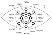
- the center position P1 is defined by the center fixation viewpoint fc (the center fixation light source 38a (the center light source portion 38c)), set in the corneal endothelial cell S2c, and photographed by the corneal endothelial cell photographing optical system 35. This is the shooting position.
- one of the enlarged light source portions 38d (see FIG. 8 and the like) of the central fixation light source 38a of the internal fixation viewpoint projection optical system 38 is turned on, and an adjacent fixed viewpoint (illustration is shown) adjacent to the central fixation point fc in the objective window 33h. And the adjacent fixation point is projected onto the eye E to be examined. Since the adjacent fixed viewpoint is formed at a position substantially equal to the center fixed viewpoint fc in the objective window 33h, the example shown in FIG. This adjacent fixation point illuminates a position slightly deviating in the X-axis direction from the center position (on the optical axis O1) of the objective window 33h.
- the line of sight of the subject (the optical axis center of the eye E) can be fixed at a position slightly off in the X-axis direction from the center position (on the optical axis O1) in the objective window 33h. Therefore, by performing the imaging operation of the corneal endothelium S2c of the corneal endothelium S2 described above while forming the adjacent fixation point, as shown in FIG. 17, slightly from the center position P1 of the eye E to the X-axis direction as shown in FIG.
- the corneal endothelial cell image J of the corneal endothelial cell S2c of the corneal endothelium S2 at the deviated enlarged position P2 can be acquired.
- the two enlarged light source portions 38d of the central fixation light source 38a are provided, two adjacent fixation viewpoints can be formed, and the corneal endothelial cell S2c at the two enlarged positions P2 can be imaged. .
- this expansion position P2 is shown individually, the right side is an expansion position P2a and the left side is an expansion position P2b when FIG. 17 is viewed from the front.
- the two enlarged positions P2 are defined by two adjacent fixed viewpoints (two enlarged light source portions 38d), and are set in the corneal endothelial cell S2c and photographed by the corneal endothelial cell photographing optical system 35. Become.
- one of the eight internal peripheral fixation light sources 38b (see FIG. 8 and the like) of the internal fixation viewpoint projection optical system 38 is turned on, and as shown in FIG. 9B, the center position (optical axis) in the objective window 33h.
- an inner peripheral fixation viewpoint fi (referred to as an inner peripheral fixation viewpoint fig as will be described later) is formed at a lower position on O1 and this inner peripheral fixation viewpoint fig is projected onto the eye E to be examined.
- This inner peripheral fixation viewpoint fig illuminates the position below the center position (on the optical axis O1) in the objective window 33h, so that the subject is gaze as a fixation target.
- the person's line of sight (the optical axis center of the eye E) can be fixed below the center position (on the optical axis O1) in the objective window 33h. For this reason, in the eye E, the center of the optical axis (line of sight) moves below the optical axis O1 of the anterior ocular segment observation optical system 33, and the light in the eye E to be examined is on the optical axis O1. A position above the axis center (see reference numeral P3c in FIG. 16) is located. Therefore, by performing the above-described imaging operation of the corneal endothelial cell S2c of the corneal endothelium S2 while forming the inner peripheral fixation point fig, as shown in FIG.
- the corneal endothelium S2 at the inner peripheral position P3c of the eye E to be examined is shown.
- the corneal endothelial cell image J of the corneal endothelial cell S2c can be acquired.
- Endothelial cells S2c can be photographed. Since eight internal peripheral fixation light sources 38b are provided, eight inner peripheral fixation viewpoints fi can be formed, and imaging of corneal endothelial cells S2c at eight internal peripheral positions P3 can be performed.
- the correspondence relationship is such that the inner peripheral fixation point fi formed on the objective window 33h (see FIG. 9B) with respect to the optical axis O1 and the inner peripheral position based on the inner peripheral fixation point fig and the internal peripheral position P3c.
- the position of P3 with respect to the optical axis center on the eye E to be examined is point-symmetric with respect to the optical axis O1 (optical axis center) in a state where the optical axis O1 and the optical axis center face each other and coincide with each other.
- the distance from the optical axis center of the inner peripheral position P3 in the eye E to be examined can be set by the distance between the optical axis O1 and the inner peripheral fixation point fi on the objective window 33h.
- the eight inner peripheral positions P3 are light beams from the inner peripheral position P3a (inner peripheral fixed viewpoint fia (see FIG. 9B)) on the right side in FIG. They are provided at intervals of 45 degrees when viewed in the rotation direction around the axis center (optical axis O1).
- the eight inner peripheral positions P3 are defined by the eight inner peripheral fixation viewpoints fia (eight inner peripheral fixation light sources 38b), set in the corneal endothelial cell S2c, and photographed by the corneal endothelial cell photographing optical system 35. This is the shooting position.
- the outer peripheral fixation light is positioned at the diagonally upper left position outside the objective window 33h.
- a viewpoint fo referred to as an outer peripheral fixed viewpoint foc as described later
- this outer peripheral fixed viewpoint foc is projected onto the eye E to be examined. Since the outer peripheral fixation point foc is lit at a position on the upper left side outside the objective window 33h, the gaze of the subject (eye to be examined) can be obtained by having the subject gaze as a fixation target.
- the center of the optical axis of E) can be fixed to the upper left side of the objective window 33h (upper right side as viewed from the front in FIG. 16). For this reason, in the eye E, the optical axis center (line of sight) moves to the upper left side of the optical axis O1 of the anterior ocular segment observation optical system 33 (upper right side in FIG. 16). Is located at an obliquely lower right position from the optical axis center of the eye E (the obliquely lower left side (see reference numeral P4d in FIG. 16).
- the corneal endothelial cell S2c of the corneal endothelium S2 can be photographed.
- the corneal endothelial cell S2c can be photographed.
- six external peripheral fixation light sources 32 are provided, six outer peripheral fixation viewpoints fo can be formed, and imaging of corneal endothelial cells S2c at six external peripheral positions P4 can be performed.
- the correspondence relationship is such that the position of the formed outer peripheral fixation point fo relative to the optical axis O1 in the periphery of the objective window 33h (see FIG. 9C), such as the outer peripheral fixation point foc and the external peripheral position P4d, and the external periphery thereby.
- the position P4 is point-symmetric with respect to the optical axis O1 (optical axis center) in a state where the position of the position P4 with respect to the optical axis center on the eye E is aligned with the optical axis O1 coincident with the optical axis center.
- the distance from the optical axis center of the external peripheral position P4 in the eye E to be examined can be set by the distance between the optical axis O1 and the outer peripheral fixation point foc in the apparatus main body 13.
- the six external peripheral positions P4 are from the external peripheral position P4a (outer peripheral fixed viewpoint foa (see FIG. 9C)) diagonally to the upper right in FIG. , Three are provided at intervals of 45 degrees when viewed in the rotation direction centered on the optical axis center (optical axis O1), and the external peripheral position P4d (outer peripheral fixed viewpoint fod (see FIG. 9C), which is also obliquely lower left. )) To three at intervals of 45 degrees when viewed in the rotation direction centered on the optical axis center (optical axis O1).
- the six external peripheral positions P4 are defined by the six outer peripheral fixation points fo (six external peripheral fixation light sources 32), set in the corneal endothelial cell S2c, and photographed by the corneal endothelial cell photographing optical system 35. This is the shooting position.
- the internal fixation point projection optical system 38 is formed in addition to the center position P1 corresponding to the central fixation point fc formed by the internal fixation point projection optical system 38.
- Two enlarged positions P2 corresponding to two adjacent fixed viewpoints see FIG. 17
- the corneal endothelial cell S2c is imaged at any of these positions, the number of positions to be imaged, the order in which the corneal endothelial cell S2c is imaged at a plurality of positions, etc. There is a risk that the management of this will become complicated, and the operation for executing it will be complicated. Further, when photographing the corneal endothelial cell S2c at a plurality of positions, which position is to be photographed from now, which position is to be photographed next, and a position that has been set and has not yet been photographed There is a risk that it may be difficult to grasp which is the position where the image has been taken, and which position has already been shot.
- the imaging position for imaging the corneal endothelial cell S2c of the corneal endothelium S2 in the eye E is set in advance, and the imaging operation of the corneal endothelial cell S2c is executed according to the setting. Is possible. Then, in the corneal endothelial cell imaging device 10, when there are a plurality of set imaging positions, it is possible to automatically set the imaging order and to manually set the imaging order. ing.
- the measurement state indication symbol 70 is displayed on the display surface 14a of the display unit 14 when the imaging operation of the corneal endothelial cell S2c is executed (FIG. 20 etc.).
- the measurement state indication symbol 70 basically enables the grasping of the photographing position to be photographed from now on and the grasping of the photographing position scheduled to be photographed next.
- the measurement state sign symbol 70 is used to grasp the set shooting position that has not been shot yet, in addition to the shooting position to be shot from now and the shooting position to be shot next. It is possible to grasp the shooting position and grasp the position that is not set. These will be described below.
- the photographing type setting screen Sk (see FIG. 18) and the photographing position setting screen Sp (see FIG. 19) are displayed on the display surface 14a of the display unit 14.
- Reference an anterior ocular segment observation screen So (see FIG. 20), and an imaging result screen Sr (see FIG. 21) can be displayed.
- the imaging type setting screen Sk is used to set the type of operation for imaging the corneal endothelial cell S2c.
- a photographing mode setting symbol 51 as an icon that enables a selection (switching) operation by touching using the function of the touch panel in the display unit 14, and the measurement eye A setting symbol 52 is displayed.
- the shooting mode setting symbol 51 is used to select one of shooting modes from preset shooting modes and set the execution of the shooting mode.
- the shooting mode setting symbol 51 includes a center shooting symbol 51a, a center enlarged shooting symbol 51b, and an arbitrary position shooting symbol 51c.
- the central imaging symbol 51a sets a central imaging mode for imaging the corneal endothelial cell S2c of the corneal endothelium S2 at the central position P1 of the eye E.
- the center enlargement imaging symbol 51b sets a center enlargement imaging mode for imaging the corneal endothelial cell S2c of the corneal endothelium S2 at the two enlargement positions P2 in addition to the center position P1 of the eye E.
- Arbitrary position photographing symbol 51c sets an arbitrary position photographing mode for photographing corneal endothelial cell S2c of corneal endothelium S2 at an arbitrary position of eye E to be examined.
- the examiner arbitrarily sets a position (photographing position) at which the eye E wants to photograph the corneal endothelial cell S2c and photographs the corneal endothelial cell S2c at the set photographing position.
- the number of shooting positions to be set can be one or more, and can be arbitrarily set.
- the center position P1, the two enlarged positions P2, the eight internal peripheral positions P3, and the six external peripheral positions P4 set as described above are selected. Selection of the shooting position in the arbitrary position shooting mode is performed on the shooting position setting screen Sp (see FIG. 19). This will be described later.
- the measurement eye setting symbol 52 sets whether to image the corneal endothelial cell S2c of the corneal endothelium S2 of the subject eye E on the left or right side of the subject.
- the measurement eye setting symbol 52 includes a right eye selection symbol 52a, a binocular selection symbol 52b, and a left eye selection symbol 52c.
- the right eye selection symbol 52a is set to image the corneal endothelial cell S2c of the subject eye E on the right side of the subject.
- the binocular selection symbol 52b is set to image the corneal endothelial cells S2c of both the left and right eye E of the subject.
- the left eye selection symbol 52c is set to image the corneal endothelial cell S2c of the subject eye E on the left side of the subject.
- the photographing position setting screen Sp (see FIG. 19), when the arbitrary position photographing symbol 51c of the photographing mode setting symbol 51 is selected and the arbitrary position photographing mode is set, the corneal endothelial cell S2c is photographed in the arbitrary position photographing mode.
- the shooting position to be set is set.
- 54 and a decision symbol 55 are displayed.
- the position selection symbol 53 is set as an imaging position by selecting an arbitrary position from among the 17 positions set in the eye E, and is displayed to be equal to both the left and right eyes E.
- the position selection symbol 53 on the left side corresponds to the eye E to be examined on the right side of the subject, and is also referred to as the position selection symbol 53a when distinguishing between left and right.
- the position selection symbol 53 on the right side corresponds to the eye E to be examined on the left side of the subject.
- Each position selection symbol 53 has one center position symbol C1, two enlarged position symbols C2, eight internal peripheral symbols C3, and six external peripheral symbols C4.
- the center position symbol C1 is provided corresponding to the center position P1 (see FIGS. 16 and 17) that can be photographed by the eye E.
- the two enlarged position symbols C2 are provided corresponding to the enlarged position P2 (see FIG. 17) that can be photographed in the eye E, the enlarged position symbol C2a corresponds to the enlarged position P2a, and the enlarged position P2b.
- the enlarged position symbol C2b corresponds.
- the letter “N” is attached to the enlarged position symbol C2a corresponding to the right eye E, whereas the letter “T” is assigned to the enlarged position symbol C2a corresponding to the left eye E. Letters are attached. This is the same even if the enlarged position symbol C2b is reversed only on the left and right. This is because the letter “N” indicates the nose and the letter “T” indicates the temple, and the positional relationship on the subject's face is reversed from side to side.
- Eight internal peripheral symbols C3 are provided corresponding to each internal peripheral position P3 (see FIG. 16) that can be photographed in the eye E. That is, the internal peripheral symbol C3 is, for example, a lowercase alphabet (a to h) added after the symbol C3 so that the internal peripheral symbol C3b corresponds to the internal peripheral position P3b. This corresponds to the internal peripheral position P3 (see FIG. 16) that coincides with (a to h).
- the six external peripheral symbols C4 are provided corresponding to each external peripheral position P4 (see FIG. 16) that can be photographed by the eye E. That is, the external peripheral symbol C4 is, for example, a lowercase alphabet (a to f) added after the symbol C4 so that the external peripheral symbol C4d corresponds to the external peripheral position P4d. This corresponds to the external peripheral position P4 (see FIG. 16) that matches (a to f).
- the position selection symbol 53 is configured by arranging each symbol (C1 to C4) so as to be adapted to the position (P1 to P4) at which the corneal endothelial cell S2c can be imaged in the corresponding eye E. Has been. For this reason, the position selection symbol 53 makes it possible to intuitively select an arbitrary position in the corresponding eye E to be examined.
- the position selection symbol 53 it is possible to grasp at a glance whether or not each of the 17 symbols (C1 to C4) has been selected.
- the position selection symbol 53 changes the color of each symbol before and after being selected (in the example shown in FIG. 19, the center position symbol C1, the internal peripheral symbol C3d, and the internal peripheral symbol C3e). , See internal peripheral symbol C3f). This is because the position selection symbol 53 assumes that a plurality of symbols can be selected.
- the patient selection symbol 54 is provided to return to a screen (not shown) for selecting a patient (subject).
- the screen for selecting the patient (subject) is displayed on the display surface 14a of the display unit 14 before the above-described photographing type setting screen Sk (see FIG. 18). This is because the corneal endothelial cell imaging apparatus 10 can manage various data such as past measurement results and measurement positions for each patient (subject).
- the determination symbol 55 is operated when the setting or operation on the screen displayed on the display surface 14a of the display unit 14 is completed, and is shifted to the next step by the operation. In other words, the determination symbol 55 is operated when the setting on the screen displayed on the display surface 14a of the display unit 14 is completed, or when there is no problem with the operation on the screen.
- This determination symbol 55 is operated when the setting of each photographing position by selection of each symbol of the position selection symbol 53 is completed in the scene displayed on the photographing position setting screen Sp, and the eye E
- the operation for photographing the corneal endothelial cell S2c of the corneal endothelium S2 at each photographing position set in (1) is started.
- the anterior ocular segment observation screen So (see FIG. 20) is an anterior segment (anterior segment image E ′) of the subject eye E for photographing the corneal endothelial cell S2c of the corneal endothelium S2 at an arbitrary photographing position of the subject eye E. ).
- selection by touching using the function of the touch panel in the display unit 14 together with the image display area 56, the measurement state indication symbol 70, and the side indication symbol 57.
- a chin rest movement symbol 58 is displayed as an icon allowing operation.
- the decision symbol 55 is a virtual image R ′′ of the alignment index light in the anterior segment image E ′ displayed in the image display area 56 as will be described later in the scene displayed on the anterior segment observation screen So.
- the photographing of the corneal endothelial cell S2c at the position is executed.
- photography of this corneal endothelial cell S2c may be performed by touching the anterior eye part image E '(the pupil) displayed on the image display area 56.
- the image display area 56 displays the anterior segment image E ′ of the eye E and the virtual image R ′′ of the alignment index light acquired by the anterior segment observation optical system 33 (the image sensor 33g). It becomes a place. That is, in the image display area 56, an image based on the light reception signal from the image sensor 33g is displayed in real time (immediately).
- the image display area 56 is a display for the examiner to observe the state of the anterior segment of the eye E, and confirms the position of the virtual image R ′′ of the alignment index light in the anterior segment image E ′. Is possible.
- the examiner confirms the position of the virtual image R ′′ of the alignment index light in the anterior segment image E ′ in the anterior segment image E ′ on the anterior segment observation screen So, so that the corneal endothelium in the subject eye E
- the imaging position where the imaging of the cell S2c is executed can be confirmed.
- the measurement state sign symbol 70 is used for each eye E to grasp the photographing position to be photographed now, grasp the photographing position scheduled to be photographed next, grasp the photographing position that has been set and has not yet been photographed, It is possible to grasp the photographing position that has already been photographed and grasp the position that is defined by each fixed viewpoint and is not set.
- the measurement state marking symbols 70 are displayed one by one on the left and right outer sides of the image display area 56 in front view of FIG. 20 corresponding to the left and right eyes E, respectively. The display contents in the measurement state sign symbol 70 will be described later.
- each measurement state indication symbol 70 indicates whether each measurement state marking symbol 70 displayed one by one on the left or right indicates the left or right eye E to be examined. This is because, in this embodiment, each of the measurement state indication symbols 70 corresponds to which of the left and right eye E to be examined corresponds to the subject's eye E depending on the state of the display unit 14. Because it is supposed to change.
- each measurement state indication symbol 70 has the display surface 14a facing the examiner side (Z-axis direction negative side) as the display unit 14 shown in FIG. 2 (the same is also shown by the solid line in FIG. 1). 20, the right side corresponds to the left eye E and the left side corresponds to the right eye E.
- each measurement state indication symbol 70 is in a state where the display unit 14 is in a state indicated by a two-dot chain line in FIG. 1 and the display surface 14a is directed to the subject side (Z-axis direction positive side) Although illustration is omitted, it is assumed that the right side corresponds to the right eye E and the left side corresponds to the left eye E in FIG.
- each measurement state marking symbol 70 is displayed on the side (side) that coincides with the left-right direction of the subject's eye E based on the person (examiner) who is looking at the display surface 14a of the display unit 14. To correspond.
- Each side marking symbol 57 makes it possible to determine which eye E to which the measurement state marking symbol 70 displayed in close proximity corresponds to.
- the side marking symbol 57 is also displayed on the imaging position setting screen Sp (see FIG. 19), and on the imaging position setting screen Sp, the left or right of each position selection symbol 53 is the subject.
- each position selection symbol 53 is displayed on the imaging position setting screen Sp in the same way as each measurement state indication symbol 70. It is good also as what changes whether it corresponds to E.
- the chin rest movement symbol 58 is used to move the chin rest 15 (see FIG. 1) up and down.
- the imaging result screen Sr (see FIG. 21) enables confirmation of the measurement result, that is, the acquired (captured) corneal endothelial cell image J (imaging result) and its analysis result.
- the touch is performed using the function of the touch panel in the display unit 14 together with the acquired image area 61, the analyzed image area 62, the acquired position indication symbol 63, and the analyzed result display area 64.
- a re-photographing symbol 65 and an output symbol 66 are displayed as icons that enable the selection (switching) operation by.
- a patient selection symbol 54 a determination symbol 55, side indication symbols 57, and measurement state indication symbols 70 similar to those on the imaging position setting screen Sp (see FIG. 19) are displayed.
- the decision symbol 55 starts an operation for photographing the corneal endothelial cell S2c of the corneal endothelium S2 at the next set photographing position in the scene displayed on the photographing result screen Sr.
- the acquired image region 61 is a place where a corneal endothelial cell image J as a photographing result of the corneal endothelial cell S2c of the corneal endothelium S2 at an arbitrary photographing position of the eye E is displayed.
- the examiner can determine whether the acquired (captured) corneal endothelial cell image J (imaging result) is good or bad by looking at the acquired image area 61.
- the analysis image area 62 is a place for displaying a cell analysis image Ja as an analysis result obtained by analyzing the acquired corneal endothelial cell image J.
- the cell analysis image Ja is shown by dividing each cell by detecting each cell in the corneal endothelial cell image J by the control unit 21 (see FIG. 3) analyzing the image of the corneal endothelial cell image J. Is.
- the control unit 21 calculates various numerical values by performing analysis based on the result of the image analysis, that is, each partitioned cell.
- the acquisition position indication symbol 63 indicates which imaging position in the eye E the corneal endothelial cell image J displayed in the acquisition image area 61 and the cell analysis image Ja displayed in the analysis image area 62 are at. It is possible to grasp by. The examiner looks at the acquired position sign symbol 63, and the corneal endothelial cell image J in the acquired image area 61 and the cell analysis image Ja in the analysis image area 62 are taken at any imaging position in the eye E. You can check if it exists.
- the analysis result display area 64 is a place for displaying various numerical values as analysis results of the corneal endothelial cell image J (cell analysis image Ja) by the control unit 21 (see FIG. 3).
- a square distribution graph 64a and a screen distribution graph 64b are displayed at the right end.
- a corneal thickness 64c, a cell density 64d variation coefficient 64e, and a hexagonal cell appearance rate 64f are displayed.
- the analysis cell number 64g, the minimum cell area 64h, the maximum cell area 64i, the average cell area 64j, and the cell area standard deviation 64k are shown below them.
- the contents (graph and numerical value) displayed in the analysis result display area 64 may be set as appropriate and are not limited to the present embodiment.
- the re-imaging symbol 65 images the corneal endothelial cell S2c again at the imaging position displayed on the acquisition position indication symbol 63, that is, the imaging position where the corneal endothelial cell S2c is imaged again (acquires the corneal endothelial cell image J) (cornea). For the acquisition of the endothelial cell image J).
- This re-photographing symbol 65 is the same when the examiner looks at the corneal endothelial cell image J as the photographing result of the acquired image region 61 and the cell analysis image Ja and the analysis result display region 64 of the analysis image region 62 as the analysis result.
- the operation is performed when it is thought that it is better to re-capture the corneal endothelial cell S2c at the photographing position, or when it is desired to photograph the corneal endothelial cell S2c at the same photographing position as a test.
- the output symbol 66 is for printing the contents displayed on the photographing result screen Sr. Note that the output symbol 66 may be output to the external device, instead of printing, the contents (its data) displayed on the imaging result screen Sr.
- the measurement state sign symbol 70 has one center position sign point 71, eight internal peripheral sign points 72, and six external peripheral sign points 73.
- the center position indicating point 71 corresponds to the center position P1 (see FIGS. 16 and 17) that can be imaged by the eye E.
- the eight internal peripheral marking points 72 correspond to the respective internal peripheral positions P3 (see FIG. 16) that can be photographed by the eye E. That is, the internal peripheral marking point 72 is, for example, a lowercase alphabet (a to h) attached after the reference numeral 72 so that the internal peripheral indication point 72f corresponds to the internal peripheral position P3f. Corresponds to the internal peripheral position P3 (see FIG. 16) that coincides with the alphabet (a to h).
- the six external peripheral marking points 73 correspond to the respective external peripheral positions P4 (see FIG. 16) that can be taken by the eye E. That is, the outer peripheral marking point 73 is, for example, a lowercase alphabet (a to f) added after the symbol 73 so that the outer peripheral marking point 73c corresponds to the outer peripheral position P4c. Corresponds to the external peripheral position P4 (see FIG. 16) that matches the alphabet (a to h).
- the measurement state indication symbol 70 is adapted to each of the indication points (71, 72, 73) in accordance with the position (P1, P3, P4) where the corresponding corneal endothelial cell S2c can be imaged in the subject eye E. ) Is arranged. For this reason, the measurement state indication symbol 70 makes it possible to intuitively recognize an arbitrary imaging position in the eye E.
- the measurement state marking symbol 70 may be provided with two marking points in accordance with the two enlarged positions P2 where the corneal endothelial cell S2c can be photographed in the corresponding eye E to be examined.
- each indication point (71, 72, 73) can be grasped at a glance at which of the five states. This is because, in the measurement state indication symbol 70 of the present embodiment, grasping of the photographing position to be photographed from now on (state Va), grasping of the photographing position scheduled to be photographed next (state Vb), setting A capturing position that has been taken but has not yet been captured (state Vc), a capturing position that has already been captured (state Vd), and a position that is defined by each fixation point and is not set This is because the position can be grasped (state Ve). In this measurement state indication symbol 70, in order to make it possible to grasp at a glance which of the five states, the color at each indication point is changed and the display mode is changed.
- the indication point of the state Va of the photographing position to be photographed from now on is shown in green, and the indication point of the state Vb of the photographing position scheduled to be photographed next is filled in orange.
- the marking point of the shooting position state Vc that has been set and has not yet been shot is shown in white
- the marking point of the shooting position state Vd that has already been shot is shown in orange
- the inside is drawn out
- other (setting (Not shown) the marking point of the photographing position state Ve is shown in white while being white.
- the center position marking point 71 is a marking point of the shooting position to be shot from now on, and is in a state Va and is filled with green.
- the internal peripheral marking point 72e is a marking point at a shooting position scheduled to be shot next, and is in a state Vb and is filled with orange.
- the internal peripheral marking point 72f is set as a marking point at a shooting position that has been set and has not yet been shot, and is set to the state Vc and is filled with white.
- the internal peripheral marking point 72d is a marking point at the photographing position that has already been photographed, and the state Vd is set to orange and the interior is removed.
- other marking points that is, five internal peripheral marking points 72 (72a, 72b, 72c, 72g, 72h) and six external peripheral marking points 73 are other (not set) positions.
- the marking point is set to the state Ve, and the inside is removed while being white.
- the measurement state indication symbol 70 can grasp at a glance the shooting position where the current shooting is to be performed and the shooting position where the next shooting is scheduled.
- the measurement state indication symbol 70 makes it possible to grasp at a glance the shooting positions that have been set but have not yet been shot, the shooting positions that have already been shot, and other (not set) positions. be able to.
- the five states (Va to Ve) at each position can be grasped.
- the shooting position (the state (state Va)) to be shot from now on and the shooting position (the state (state Va)) to be shot next If it is possible to grasp that state (state Vb)), another state (a shooting position that has been set and has not been shot yet (that state (state Vc)), a shooting position that has already been shot (that is, The state (state Vd)) and other (not set) positions (that state (state Ve))) may be capable of grasping only one of them, and may be combined as appropriate.
- the present invention is not limited to this embodiment.
- FIG. 23 is a flowchart illustrating display control processing executed by the control unit 21 in the present embodiment. Hereinafter, each step of the flowchart of FIG. 23 will be described.
- a plurality of photographing positions for photographing the corneal endothelial cell S2c are set by selection with each position selection symbol 53 on the photographing position setting screen Sp, and the photographing order will be described later. The operation starts simultaneously with the flow chart of FIG. The flowchart of FIG.
- the control unit 21 acquires information on the set shooting positions, the number of the shooting positions, and the shooting order. Then, the control unit 21 stores (stores) the number k of the set photographing positions in the storage unit 21a, and extracts a marking point (see FIG. 22) of the measurement state marking symbol 70 corresponding to the set photographing position. Then, the shooting order r set at each shooting position is set to each extracted point. Further, the count number n used in this flowchart is linked with the count number n used in the flowchart of FIG.
- step S11 the extracted marking points are set to the state Vc, and the remaining marking points are set to the state Ve, and the process proceeds to step S12.
- step S11 all the marking points extracted regardless of the order are set to the state Vc, and in the present embodiment, each marking point is painted in white.
- step S11 the remaining marking points are set to the state Ve, and in this embodiment, the marking points are white and the interior is removed.
- step S13 since the photographing operation of the corneal endothelial cell S2c at the n-th photographing position is executed, the next photographing is performed at the (n + 1) -th photographing position.
- step S12 the display state of each display unit is changed in the order of step S12, step S13, and step S14.
- the order of these steps may be changed, and the present embodiment is performed. It is not limited to examples.
- step S13 and step S14 depending on the value of the count number n, there may be a case where the corresponding marking point does not exist. In this case, the corresponding step (process) is not executed and the next step (process) is performed. And proceed.
- an imaging type setting screen Sk (see FIG. 18) corresponding to the selected patient (subject) is displayed. 14 on the display surface 14a.
- the photographing mode is set by the photographing mode setting symbol 51 and the right eye E to be examined is set as the photographing target of the corneal endothelial cell image J by the measurement eye setting symbol 52.
- the right eye selection symbol 52a or the left eye selection symbol 52c both eyes are selected by the binocular selection symbol 52b for the one eye E to be examined.
- the center shooting mode setting symbol 51 it is assumed that the center shooting mode is set by the center shooting symbol 51a. Then, the center light source 38c (see FIG. 8 and the like) of the center fixation light source 38a of the internal fixation point projection optical system 38 is turned on to form the center fixation point fc in the objective window 33h (see FIG. 9A and the like).
- the above-described photographing operation of the corneal endothelial cell S2c of the corneal endothelium S2 is executed. This operation is performed on both eyes E. As a result, a corneal endothelial cell image J of the corneal endothelial cell S2c of the corneal endothelium S2 at the center position P1 of both eyes E is acquired (see FIG. 16 and the like).
- the center enlargement shooting mode is set by the center enlargement shooting symbol 51b.
- the center light source 38c (see FIG. 8 and the like) of the center fixation light source 38a of the internal fixation point projection optical system 38 is turned on to form the center fixation point fc in the objective window 33h (see FIG. 9A and the like).
- the above-described photographing operation of the corneal endothelial cell S2c of the corneal endothelium S2 is executed. Thereafter, one enlarged light source unit 38d (see FIG.
- the central fixation light source 38a of the internal fixation viewpoint projection optical system 38 is turned on, and one adjacent fixation point adjacent to the central fixation point fc in the objective window 33h ( The above-described imaging operation of the corneal endothelial cell S2c of the corneal endothelium S2 is executed. Thereafter, the other enlarged light source 38d (see FIG. 8 and the like) of the center fixation light source 38a of the internal fixation point projection optical system 38 is turned on, and the other adjacent fixation point adjacent to the center fixation point fc in the objective window 33h ( The above-described imaging operation of the corneal endothelial cell S2c of the corneal endothelium S2 is executed.
- This operation is performed on both eyes E.
- the corneal endothelial cell image J of the corneal endothelial cell S2c of the corneal endothelium S2 at the center position P1 of both eyes E and the two enlarged positions P2 adjacent to both sides thereof is acquired (see FIG. 17 and the like).
- the order of photographing the corneal endothelial cell S2c at the center position P1 and the two enlarged positions P2 may be any order and is not limited to the present embodiment.
- the arbitrary position shooting mode is set by the arbitrary position shooting symbol 51c.
- the photographing position setting screen Sp (see FIG. 19) is displayed on the display surface 14a of the display unit 14.
- the decision symbol 55 is operated to photograph the selected position at the corneal endothelial cell S2c in the eye E to be examined.
- Set the shooting position When a plurality of imaging positions are set (selected) by each position selection symbol 53, the order of imaging the corneal endothelial cell S2c at the selected plurality of imaging positions is set.
- the setting of this order can be performed, for example, from the viewpoint of enabling the corneal endothelial cell S2c to be imaged efficiently.
- This efficient shooting means for example, for shooting at each shooting position, as described above, the corresponding fixed viewpoints (center fixed viewpoint fc, two adjacent fixed viewpoints, eight inner peripheral fixed viewpoints fi and six Since it is necessary to have the subject gaze at one of the outer peripheral fixation viewpoints fo) as a fixation target, it is conceivable to reduce the amount of movement of the subject's line of sight. This is because if the amount of movement of the line of sight is small, the burden on the subject is lightened and it is easy to gaze as a fixation target.
- the order may be set, for example, in the order in which each symbol is selected in each position selection symbol 53, or may be set as appropriate by a program set in advance.
- the present invention is not limited to this embodiment.
- the order may be set by the examiner (user).
- the setting by the examiner (user) can be set in the order in which each symbol is selected in each position selection symbol 53, for example.
- the setting by the examiner (user) is, for example, to obtain an operation for setting the order of the set shooting positions after each shooting position is set (selected) by each position selection symbol 53. Also good.
- both the setting by the examiner (user) and the automatic setting by the control unit 21 can be selected.
- FIG. 24 is a flowchart illustrating a continuous acquisition control process executed by the control unit 21 in the present embodiment. Hereinafter, each step of the flowchart of FIG. 24 will be described.
- an arbitrary position imaging mode is set, and as described above, a plurality of imaging positions in the corneal endothelial cell S2c are set by selection with each position selection symbol 53 on the imaging position setting screen Sp, and the imaging order is set. It is started by setting. And the control part 21 acquires the information of each set imaging
- photography order. Then, the number k of the set shooting positions is stored (stored) in the storage unit 21a, and a fixed viewpoint (light source forming the same) corresponding to each set shooting position is extracted and set to each shooting position. The shooting order r is set for each extracted fixed point (light source). The number k described above is equal to the display control process (flowchart in FIG. 23) described above. Further, in this flowchart, a variable n is used to count the currently set operation position for imaging of the corneal endothelial cell S2c. When starting this flowchart, n 1.
- the following operation is performed in this embodiment.
- the examiner positions the virtual image R ′′ of the alignment index light on the anterior segment image E ′ displayed on the anterior segment observation screen So at the imaging position where the corneal endothelial cell S2c is to be captured. Judge whether there is. If XY alignment is not appropriate, XY alignment is performed again. Further, when appropriate, the decision symbol 55 displayed on the anterior ocular segment observation screen So is operated, or the anterior ocular segment image E ′ (its pupil) of the image display area 56 displayed on the anterior ocular segment observation screen So. Touch.
- the apparatus main body 13 is appropriately moved in the Z-axis direction (front-rear direction) with respect to the base 11, Z alignment is performed, and the corneal endothelial cell photographing optical system 35 is moved to the corneal endothelial cell S2c. Focus on. Thereafter, as described above, the corneal endothelial cell S2c of the corneal endothelium S2 of the eye E to be examined is photographed with visible light (imaging light beam) to obtain a corneal endothelial cell image J (see FIG. 15 and the like). Then, a cell analysis image Ja (see FIG. 21) is generated, and the cell analysis image Ja (corneal endothelial cell image J) is analyzed to calculate various numerical values as a result of the image analysis.
- step S23 following execution of imaging of the corneal endothelial cell S2c of the corneal endothelium S2 in step S22, the imaging result screen Sr (see FIG. 21) is displayed on the display unit 14 (the display surface 14a), and the process proceeds to step S24. move on.
- an imaging result screen Sr is generated based on the corneal endothelial cell image J acquired in step S22, the generated cell analysis image Ja, and the calculated image analysis, and the imaging result screen Sr is displayed on the display surface of the display unit 14. 14a is displayed.
- step S24 following the display of the photographing result screen Sr (see FIG. 21) in step S23, it is determined whether or not there is an operation with no problem with the measurement result displayed on the photographing result screen Sr. Advances to step S25, and returns No to step S22 if No. In this step S25, it is determined whether or not an operation that the measurement result displayed on the imaging result screen Sr has no problem is performed. In step S25, in this embodiment, it is determined that the measurement result has no problem when the determination symbol 55 is operated on the photographing result screen Sr, and the measurement result is obtained when the re-photograph symbol 65 is operated. It is determined that there was an operation with a problem.
- step S25 since the operation of the decision symbol 55 means that an operation for photographing at the next photographing position has been performed, the examiner who has seen the photographing result screen Sr is displayed on the photographing result screen Sr. Judged that the measurement results were satisfactory.
- the operation of the re-photographing symbol 65 means that an operation for re-imaging of the corneal endothelial cell S2c (acquisition of the corneal endothelial cell image J) at the same imaging position has been performed. It is determined that the examiner who has seen the result screen Sr has obtained an image that there is a problem with the measurement result displayed on the imaging result screen Sr.
- the measurement result includes both the corneal endothelial cell image J as the imaging result, and the cell analysis image Ja and the numerical values of the image analysis as the analysis results.
- 1 is added to a variable n (its current value) for counting the currently set imaging position of the corneal endothelial cell S2c currently being performed.
- n (n n + 1).
- FIG. 25 FIG. 25A to FIG. 25F showing how the display content changes in the measurement state indication symbol 70.
- FIG. 25 the measurement state indication symbol 70 similar to that in FIG. 22 is shown and shown, but the symbols (71, 72, 73) of each indication point are omitted for easy understanding. Only the reference numerals (Va, Vb, Vc, Vd, Ve) are shown.
- the arbitrary position shooting mode is set as described above, and in the shooting position setting screen Sp displayed on the display surface 14a of the display unit 14, as shown in FIG.
- the center position symbol C1 the internal peripheral symbol C3d, the internal peripheral symbol C3e, and the internal peripheral symbol C3f are selected.
- the color of each selected symbol (C1, C3d, C3e, C3f) is different from the other symbols.
- the examiner user
- the decision symbol 55 has been operated as a result of the above four selections assuming that the setting of the shooting position has been completed.
- the internal peripheral symbol C3d is set first, the center position symbol C1 is second, the internal peripheral symbol C3e is third, and the internal peripheral symbol C3f is fourth.
- the order of imaging the corneal endothelial cell S2c in the eye E is set to the internal peripheral position P3d as the first, the central position P1 as the second, the internal peripheral position P3e as the third, and the internal peripheral position P3f as the fourth. (See FIG. 16).
- the internal peripheral indication point 72d, the central position indication point 71, the internal peripheral indication point 72e, and the internal peripheral indication point 72f are set by proceeding to step S11 in the flowchart of FIG.
- the state Vc as the photographing position that has not yet been photographed is painted in white (see FIG. 25A).
- the remaining indication points are white as the state Ve as an imaging position not set.
- the inside is removed (see FIG. 25A).
- the corneal endothelial cell imaging device 10 (control unit 21) turns on one corresponding internal peripheral fixation light source 38b of the internal fixation point projection optical system 38 by proceeding to step S21 in the flowchart of FIG.
- an inner peripheral fixation point fif (see FIG. 9B) corresponding to the inner peripheral position P3d (see FIG. 16) set as the first photographing position is formed.
- the process proceeds to step S22 in the flowchart of FIG. 24, thereby causing the subject to focus on the inner peripheral fixation point fif as a fixation target.
- the imaging operation of the corneal endothelial cell S2c in S2 is executed.
- step S14 is not substantially executed, and there is no indication point to be in the state Vd.
- the measurement state marking symbol 70 shown in FIG. 25B generated in this way is an anterior ocular segment observation screen So (in the scene where the photographing operation of the corneal endothelial cell S2c at the internal peripheral position P3d which is the first photographing position is executed. 20) and the photographing result screen Sr (see FIG. 21).
- So anterior ocular segment observation screen So (see FIG.
- the measurement state indication symbol 70 indicating the eye E to be examined (side) on which the imaging operation is not performed is When the shooting (measurement) of the side (side) is not completed, the mode shown in FIG. 25A is obtained. When the shooting (measurement) of the side (side) is completed, the mode shown in FIG. It becomes.
- the aspect of the measurement state indication symbol 70 on the side where the photographing operation is not executed does not change regardless of the following operation.
- the corneal endothelial cell imaging device 10 displays the imaging result screen Sr (see FIG. 21) on the display unit 14 (its display surface 14a) by proceeding to step S23 in the flowchart of FIG. .
- the imaging result screen Sr see FIG. 21
- the decision symbol 55 is operated or the anterior eye image E ′ (its pupil) of the image display area 56 displayed on the anterior eye observation screen So is touched.
- the process proceeds from step S24 to step S25 to step S26 in the flowchart of FIG. 24, whereby the internal peripheral position P3d that is the first imaging position (see FIG. 16).
- the process proceeds to step S21 in the flowchart of FIG. 24, whereby the central light source unit 38c (FIG. 8, etc.) of the central fixation light source 38a of the internal fixation point projection optical system 38.
- the center fixation viewpoint fc (see FIG. 9A) corresponding to the center position symbol C1 (see FIG. 16) set as the second photographing position is formed.
- the corneal endothelial cell imaging device 10 controls the corneal endothelial cell imaging device 10 (control unit 21), by proceeding to step S22 in the flowchart of FIG. 24, the corneal endothelium S2 described above is performed while the subject is gazing at the central fixation point fc as a fixation target.
- the imaging operation of the corneal endothelial cell S2c is executed.
- a state Vd as an imaged position where the image has already been taken (the inside is pulled out while being orange) (see FIG. 25C).
- 25C generated in this way is an anterior ocular segment observation screen So (in the scene where the imaging operation of the corneal endothelial cell S2c at the center position symbol C1, which is the second imaging position, is executed. 20) and the photographing result screen Sr (see FIG. 21).
- the corneal endothelial cell imaging device 10 displays the imaging result screen Sr (see FIG. 21) on the display unit 14 (its display surface 14a) by proceeding to step S23 in the flowchart of FIG. .
- the imaging result screen Sr see FIG. 21
- the decision symbol 55 is operated or the anterior eye image E ′ (its pupil) of the image display area 56 displayed on the anterior eye observation screen So is touched.
- the process proceeds from step S24 to step S25 to step S26 in the flowchart of FIG. 24, whereby the center position symbol C1 that is the second imaging position (see FIG. 16).
- a state Vd as a photographing position that has already been photographed (the inside is pulled out while being orange) (see FIG. 25D).
- 25D generated in this way is an anterior ocular segment observation screen So (in the scene of performing the imaging operation of the corneal endothelial cell S2c at the internal peripheral position P3e which is the third imaging position. 20) and the photographing result screen Sr (see FIG. 21).
- the corneal endothelial cell imaging device 10 displays the imaging result screen Sr (see FIG. 21) on the display unit 14 (its display surface 14a) by proceeding to step S23 in the flowchart of FIG. .
- the imaging result screen Sr see FIG. 21
- the decision symbol 55 is operated or the anterior eye image E ′ (its pupil) of the image display area 56 displayed on the anterior eye observation screen So is touched.
- the process proceeds from step S24 to step S25 to step S26 in the flowchart of FIG. 24, whereby the internal peripheral position P3e set as the third imaging position (see FIG. 16).
- the measurement state indication symbol 70 shown in FIG. 25E generated in this way is an anterior ocular segment observation screen So (in the scene where the imaging operation of the corneal endothelial cell S2c at the internal peripheral position P3f which is the fourth imaging position is executed. 20) and the photographing result screen Sr (see FIG. 21).
- the corneal endothelial cell imaging device 10 displays the imaging result screen Sr (see FIG. 21) on the display unit 14 (its display surface 14a) by proceeding to step S23 in the flowchart of FIG. .
- the imaging result screen Sr see FIG. 21
- the decision symbol 55 is operated or the anterior eye image E ′ (its pupil) of the image display area 56 displayed on the anterior eye observation screen So is touched.
- the continuous acquisition control process is ended.
- the corneal endothelial cell imaging device 10 control unit 21
- the corneal endothelial cell image J obtained by imaging the corneal endothelial cell S2c at each position in accordance with the operation on the display unit 14 (display surface 14a) and the image The analysis result (cell analysis image Ja and image analysis result) is appropriately displayed on the display unit 14 (display surface 14a).
- the internal peripheral indication point 72f corresponding to the last imaged internal peripheral location P3f is changed to the state Vd (in orange while the internal peripheral indication point 72f is orange).
- Is taken it indicates that the shooting of all the set positions has been completed (all the four set marking portions are in the state Vd as the shooting positions already shot).
- the corneal endothelial cell imaging device 10 as one embodiment of the corneal endothelial cell imaging device according to the present invention, a fixed viewpoint corresponding to the imaging position for imaging the corneal endothelial cell S2c in the set eye E is formed, Execution of the imaging operation of the corneal endothelial cell S2c is performed for all the set imaging positions. For this reason, the examiner can photograph the corneal endothelial cell S2c at all the photographing positions set reliably without managing at which photographing position.
- the corneal endothelial cell imaging device 10 does not require complicated management from the examiner even when imaging the corneal endothelial cell S2c of the corneal endothelium S2 at a plurality of imaging positions in the eye E. Imaging of the corneal endothelial cell S2c at each set imaging position can be reliably performed, and usability can be improved.
- the corneal endothelial cell imaging device 10 performs an imaging operation of the corneal endothelial cell S2c while forming a fixed viewpoint corresponding to the imaging position of the corneal endothelial cell S2c in the set eye E to be examined. Therefore, the examiner can photograph the corneal endothelial cell S2c at each photographing position in the set eye E without performing an operation for forming the corresponding fixation point. Therefore, the corneal endothelial cell imaging device 10 does not require a complicated operation from the examiner even when imaging the corneal endothelial cell S2c of the corneal endothelium S2 at a plurality of imaging positions in the eye E. Imaging of the corneal endothelial cell S2c at each set imaging position can be reliably performed, and usability can be improved.
- the corneal endothelial cell imaging apparatus 10 can reliably perform imaging of the corneal endothelial cell S2c at each set imaging position without requiring complicated management and complicated operations from the examiner. As a result, it is possible to reduce the time required for photographing the corneal endothelial cell S2c, so that the usability can be improved and the burden on the subject can be reduced.
- the corneal endothelial cell imaging device 10 forms a fixed viewpoint corresponding to each imaging position in the set eye E according to the set order, and executes an imaging operation of the corneal endothelial cell S2c. For this reason, the examiner does not manage in which order the imaging is performed at which imaging position, but performs the imaging of the corneal endothelial cell S2c at each imaging position that has been set reliably. Can do. Therefore, the corneal endothelial cell imaging device 10 does not require complicated management from the examiner even when imaging the corneal endothelial cell S2c of the corneal endothelium S2 at a plurality of imaging positions in the eye E. Imaging of the corneal endothelial cell S2c at each set imaging position can be reliably performed in the set order, and usability can be further improved.
- the corneal endothelial cell imaging device 10 forms a fixed viewpoint corresponding to each imaging position in the set eye E according to the set order. Therefore, the examiner can shoot the set shooting positions in the set order without performing an operation for forming a fixed viewpoint corresponding to the set order. Therefore, the corneal endothelial cell imaging device 10 does not require a complicated operation from the examiner even when imaging the corneal endothelial cell S2c of the corneal endothelium S2 at a plurality of imaging positions in the eye E. Imaging of the corneal endothelial cell S2c at each set imaging position can be reliably performed in the set order, and usability can be further improved.
- the corneal endothelial cell imaging device 10 can reliably perform imaging of the corneal endothelial cell S2c at each set imaging position without requiring complicated management and complicated operations from the examiner. As a result, the time required for imaging the corneal endothelial cell S2c can be reduced, so that the usability can be improved and the burden on the subject can be reduced.
- the corneal endothelial cell imaging device 10 a plurality of arbitrary imaging positions for imaging the corneal endothelial cell S2c in the eye E can be set, and a fixed viewpoint corresponding to the set imaging position is formed to form the corneal endothelial cell.
- the execution of the shooting operation in S2c is performed for all the set shooting positions.
- the examiner can set to photograph the corneal endothelial cell S2c at an arbitrary number of photographing positions according to the state of the eye E of the subject. Therefore, the corneal endothelial cell imaging device 10 can set the imaging of the corneal endothelial cell S2c at an arbitrary imaging position by an arbitrary number and store the setting in the user (examiner).
- the corneal endothelial cell S2c can be reliably imaged at each imaging position set without management. Therefore, in the corneal endothelial cell imaging device 10, usability can be improved more effectively.
- the corneal endothelial cell imaging device 10 enables setting of a plurality of arbitrary imaging positions for imaging the corneal endothelial cell S2c in the eye E while setting the order of imaging at each set imaging position.
- the fixation point corresponding to the imaging position set according to the set order is formed, and the imaging operation of the corneal endothelial cell S2c is executed.
- the examiner can set to photograph an arbitrary number of corneal endothelial cells S2c in accordance with the state of the subject's eye E, and set the photographing order. Can do.
- the corneal endothelial cell imaging device 10 can set the imaging of the corneal endothelial cell S2c at an arbitrary imaging position in an arbitrary order in an arbitrary order, and can make the user (examiner) perform the setting. Imaging of the corneal endothelial cell S2c at each imaging position set without being stored and managed can be reliably performed in an arbitrary order. Therefore, in the corneal endothelial cell imaging device 10, usability can be improved more effectively.
- the corneal endothelial cell imaging device 10 enables setting of a plurality of arbitrary imaging positions for imaging the corneal endothelial cell S2c in the eye E while setting the order of imaging at each set imaging position. Therefore, the examiner determines the order in which the corneal endothelial cells S2c are imaged in accordance with the subject, taking into account the ease of movement of the subject's line of sight, the burden associated with the movement of the subject's line of sight, and the like. Can be set. Therefore, the corneal endothelial cell imaging device 10 can improve usability and further reduce the burden on the subject.
- the corneal endothelial cell imaging device 10 enables setting of a plurality of arbitrary imaging positions for imaging the corneal endothelial cell S2c in the eye E, and automatically sets the imaging order at each of the set imaging positions, A fixation point corresponding to the imaging position set according to the order is formed, and the imaging operation of the corneal endothelial cell S2c is executed. For this reason, the examiner only needs to set to photograph the corneal endothelial cell S2c at an arbitrary number of imaging positions according to the state of the eye E of the subject.
- the corneal endothelial cell imaging device 10 can set the imaging of the corneal endothelial cell S2c at an arbitrary imaging position by an arbitrary number and store the setting in the user (examiner).
- the imaging of the corneal endothelial cell S2c at each set imaging position can be reliably performed without management and without requiring the setting of the order. Therefore, in the corneal endothelial cell imaging device 10, usability can be improved more effectively.
- the corneal endothelial cell imaging device 10 displays the imaging result screen Sr (see FIG. 21) on the display unit 14 (the display surface 14a) every time imaging of the corneal endothelial cell S2c at the set imaging position is completed. The imaging result of the corneal endothelial cell S2c at the imaging position is confirmed. Then, in the corneal endothelial cell imaging device 10, when an operation that there is a problem with the displayed imaging result is performed on the imaging result screen Sr, the imaging operation of the corneal endothelial cell S2c at the same imaging position is performed again and displayed. If there is no problem with the obtained imaging result, the operation proceeds to the imaging operation of the corneal endothelial cell S2c at the next imaging position.
- the examiner can confirm the imaging result of the corneal endothelial cell S2c at the set imaging position, obtain a satisfactory result, and shift to imaging of the corneal endothelial cell S2c at the next imaging position. .
- the corneal endothelial cell imaging device 10 prevents the imaging of the corneal endothelial cell S2c at any imaging position from being performed again after the imaging of the corneal endothelial cell S2c at all the imaging positions set is completed. Can improve usability.
- the corneal endothelial cell imaging device 10 displays the imaging result screen Sr (see FIG. 21) on the display unit 14 (the display surface 14a) every time imaging of the corneal endothelial cell S2c at the set imaging position is completed. The imaging result and the analysis result of the corneal endothelial cell S2c at the imaging position are confirmed. Then, in the corneal endothelial cell imaging device 10, when an operation that there is a problem with the displayed imaging result or the analysis result is performed on the imaging result screen Sr, the imaging operation of the corneal endothelial cell S2c at the same imaging position again.
- the operation proceeds to the imaging operation of the corneal endothelial cell S2c at the next imaging position.
- the examiner confirms both the imaging result of the corneal endothelial cell S2c at the set imaging position and the analysis result thereof, and after obtaining both of them, the corneal endothelial cell S2c at the next imaging position is obtained. You can shift to shooting. Thereby, in the corneal endothelial cell imaging device 10, it is possible to widen the range of determination of whether the measurement result is good or bad, and the usability can be further improved.
- the measurement state indication symbol 70 is used to grasp the photographing position to be photographed now, grasp the photographing position to be photographed next, Can be made possible. For this reason, the examiner can confirm whether the photographing position to be photographed from now on is appropriate, and can confirm the photographing position to be photographed next time. From this, the examiner can easily grasp the respective shooting positions without managing the shooting position where the current shooting is to be performed and the shooting position where the next shooting is scheduled. For example, this can improve the efficiency of the examination work by the examiner and can inform the examinee the direction in which the line of sight is directed for the next imaging.
- the present operator does not require complicated management. Therefore, it is possible to surely grasp the photographing position for photographing from the next and the photographing position scheduled to be photographed next, so that the photographing of the corneal endothelial cell S2c can be made smooth and the usability can be improved.
- the examiner can check whether the shooting position to be shot from now on is appropriate, can check the shooting position where the next shooting is scheduled, and has been set and has not yet taken a shot. It is also possible to check the shooting positions and the number of the shooting positions that are not.
- the examiner can easily grasp each shooting position without managing the shooting position to be shot from now, the shooting position to be shot next, and the set shooting position that has not been shot yet. can do. For example, this can improve the efficiency of the examination work by the examiner, and can inform the subject of the direction in which the line of sight is directed for the next imaging, and the remaining number.
- the corneal endothelial cell imaging device 10 even when the corneal endothelial cell S2c of the corneal endothelium S2 is imaged at a plurality of imaging positions in the eye E, the present operator does not require complicated management.
- the photographing position to be photographed from now and the photographing position to be photographed next are set by the measurement state indicator symbol 70, and still photographing.
- the examiner can check whether the shooting position to be shot from now is appropriate, can check the shooting position to be shot next, has been set, and has not been shot yet. It is possible to check the number of shooting positions and the number of shooting positions, and the shooting positions that have already been shot can also be checked.
- the examiner can manage each of the shooting positions to be shot from now, the shooting position to be shot next, the shooting position that has not been shot yet, and the shooting position that has already been shot.
- the photographing position can be easily grasped. For example, this can improve the efficiency of the examination work by the examiner, and can inform the subject of the direction in which the line of sight is directed for the next imaging, and the remaining number. Further, since the examiner can confirm the photographing position that has already been photographed, it can be easily confirmed whether or not the photographing (setting) has been forgotten.
- the present operator does not require complicated management.
- the photographing position to be photographed from the next, the photographing position to be photographed next, the photographing position that has been set and has not yet been photographed, and the photographing position that has already been photographed can be surely grasped, and the photographing of the corneal endothelial cell S2c can be performed smoothly.
- the usability can be improved.
- the photographing position to be photographed from now and the photographing position to be photographed next are set by the measurement state indicator symbol 70, and still photographing.
- the examiner can check each set shooting position among all the positions that can be set including the positions that are not set, so the shooting position to be shot from now on is appropriate.
- the examiner can manage each of the shooting positions to be shot from now, the shooting position to be shot next, the shooting position that has not been shot yet, and the shooting position that has already been shot.
- the position can be grasped more easily. For example, this can further improve the efficiency of the examination work by the examiner, and can inform the subject of the direction in which the line of sight is directed for the next imaging and the remaining number.
- the present operator does not require complicated management.
- the photographing position to be photographed from the next, the photographing position scheduled to be photographed next, the photographing position that has been set and has not yet been photographed, and the photographing position that has already been photographed can be grasped more reliably, and the corneal endothelial cell S2c can be photographed. It can be made smooth and the usability can be further improved.
- the corneal endothelial cell imaging device 10 it is possible to grasp at a glance which state (Va to Ve (see FIG. 22 and the like)) at each marking point of the measurement state marking symbol 70. For this reason, the corneal endothelial cell imaging device 10 can further reduce the burden on the examiner who is performing the measurement operation, and can further improve the efficiency of the examination operation by the examiner.
- the corneal endothelial cell imaging device 10 as an embodiment of the corneal endothelial cell imaging device according to the present invention, even when a plurality of imaging positions in the corneal endothelial cell S2c of the eye E to be imaged are set, Usability can be improved.
- the corneal endothelial cell imaging apparatus 10 as an embodiment of the corneal endothelial cell imaging apparatus according to the present invention has been described.
- slit light irradiation optics that irradiates slit light toward the cornea of the eye to be examined.
- a corneal endothelial cell imaging optical system that receives reflected light from the corneal endothelial cells of the cornea and images the corneal endothelial cells
- the corneal endothelial cell imaging optical system A plurality of fixation points for fixing a line of sight of the eye to be examined in an arbitrary direction so as to define a photographing position of the eye to be examined in the corneal endothelial cell, and the slit light irradiation optical system
- the control unit executes the photographing operation of the corneal endothelial cell by the slit light irradiation optical system and the corneal endothelial cell photographing optical system while forming the fixed viewpoint corresponding to the set photographing position.
- Any corneal endothelial cell imaging apparatus may be
- the imaging position in the corneal endothelium S2 of the eye E to be imaged for the corneal endothelial cell S2c by the corneal endothelial cell imaging optical system 35 can be arbitrarily set. May be set automatically (by the control unit 21), and is not limited to the above-described embodiment.
- the imaging result screen Sr (see FIG. 21) is displayed on the display unit 14 (its display surface 14a), Although the imaging result of the corneal endothelial cell S2c at the imaging position is to be confirmed, the imaging operation of the corneal endothelial cell S2c at the next imaging position may be shifted to the next imaging position without confirmation.
- the present invention is not limited to the examples.
- the imaging result screen Sr see FIG. 21
- the corneal endothelial cell image J as the imaging result
- the cell analysis image Ja analysis image area 62
- various numerical values are displayed on the display unit 14 (the display surface 14a), but only the imaging result (corneal endothelial cell image J (acquired image area 61)) is displayed.
- the present invention is not limited to the above-described embodiment.
- the indication points (71, 72, 73) corresponding to all of the positions defined by the respective fixed viewpoints are provided and in which state each indication point is.
- the optical system having the configuration shown in FIG. 4 is mounted, but the slit light irradiation optical system (34) for irradiating slit light toward the cornea Ec of the eye E and the corneal endothelium of the cornea Ec.
- the slit light irradiation optical system (34) for irradiating slit light toward the cornea Ec of the eye E and the corneal endothelium of the cornea Ec.
- the optical configuration, the arrangement of each optical member, and the measurement principle are different.
- the measurement content (type) may be different, and is not limited to the above-described embodiments.
- the light shielding portion of the liquid crystal shutter 35e is obtained based on the intensity distribution of the optical image of the image sensor 33g, but the light shielding portion of the liquid crystal shutter 35e is obtained based on the intensity distribution of the light image of the line sensor 39a.
- the present invention is not limited to the above-described embodiments.
Landscapes
- Life Sciences & Earth Sciences (AREA)
- Health & Medical Sciences (AREA)
- Medical Informatics (AREA)
- Biophysics (AREA)
- Ophthalmology & Optometry (AREA)
- Engineering & Computer Science (AREA)
- Biomedical Technology (AREA)
- Heart & Thoracic Surgery (AREA)
- Physics & Mathematics (AREA)
- Molecular Biology (AREA)
- Surgery (AREA)
- Animal Behavior & Ethology (AREA)
- General Health & Medical Sciences (AREA)
- Public Health (AREA)
- Veterinary Medicine (AREA)
- Eye Examination Apparatus (AREA)
Abstract
撮影を実行する被検眼の角膜内皮細胞における撮影位置を複数設定した場合であっても、使い勝手を向上させることのできる角膜内皮細胞撮影装置を提供する。 スリット光照射光学系(34)と角膜内皮細胞撮影光学系(35)とを備える角膜内皮細胞撮影装置(10)である。被検眼Eの角膜内皮細胞(S2c)における撮影する位置を規定すべく被検眼Eの視線を任意の方向に固定する複数の固視点(fc、fi、fo)と、各固視点を形成するとともにスリット光照射光学系と角膜内皮細胞撮影光学系(35)との動作を制御する制御部(21)と、を備え、角膜内皮細胞撮影光学系(35)により撮影される角膜内皮細胞(S2c)における撮影位置(P1、P2、P3、P4)が複数設定され、制御部(21)は、設定された撮影位置に対応する固視点を形成しつつ角膜内皮細胞(S2c)の撮影動作を実行することを、設定された全ての撮影位置に対して行う。
Description
本発明は、角膜内皮細胞を撮影するための角膜内皮細胞撮影装置に関する。
従来から、被検眼の角膜に向けて斜めからスリット光を照射するためのスリット光照明光学系と、角膜からの反射光を利用して角膜内皮細胞像を観察し且つ撮影を行うための観察撮影光学系とを備える角膜内皮細胞撮影装置が知られている(特許文献1参照)。
この角膜内皮細胞撮影装置では、固視点により被検眼の視線を任意の方向に固定しつつ角膜内皮細胞撮影光学系で被検眼の角膜内皮細胞を撮影することにより、被検眼の角膜内皮細胞における任意の位置を撮影することができる。換言すると、固視点は、被検眼の視線を任意の方向に固定することにより、角膜内皮細胞撮影光学系による被検眼の角膜内皮細胞における撮影する位置を規定することができる。このため、被検眼の視線を任意の方向に固定する固視点を複数設けることにより、被検眼の角膜内皮細胞において撮影することのできる位置およびその数を増やすことができ、測定の自由度を高めることができる。
しかしながら、角膜内皮細胞撮影装置では、角膜内皮細胞において撮影することのできる位置およびその数を増やすと、いずれの位置で撮影するのかの管理が複雑なものとなり、それを実行するための操作が煩雑なものとなってしまう虞がある。このことは、角膜内皮細胞において撮影することのできる位置が6つを超えるくらいから顕著なものとなる。このため、使い勝手を向上させる観点から改善の余地が生じる。
本発明は、上記の事情に鑑みて為されたもので、撮影を実行する被検眼の角膜内皮細胞における撮影位置を複数設定した場合であっても、使い勝手を向上させることのできる角膜内皮細胞撮影装置を提供することを目的とする。
上記した課題を解決するために、請求項1に記載の角膜内皮細胞撮影装置は、被検眼の角膜に向けてスリット光を照射するスリット光照射光学系と、前記角膜の角膜内皮細胞からの反射光を受光して前記角膜内皮細胞を撮影する角膜内皮細胞撮影光学系と、を備える角膜内皮細胞撮影装置であって、前記角膜内皮細胞撮影光学系による前記被検眼の前記角膜内皮細胞における撮影する位置を規定すべく前記被検眼の視線を任意の方向に固定する複数の固視点と、前記各固視点を形成するとともに、前記スリット光照射光学系と前記角膜内皮細胞撮影光学系との動作を制御する制御部と、を備え、前記角膜内皮細胞撮影光学系により撮影される前記角膜内皮細胞における撮影位置が複数設定され、前記制御部は、設定された前記撮影位置に対応する前記固視点を形成しつつ前記スリット光照射光学系と前記角膜内皮細胞撮影光学系とによる前記角膜内皮細胞の撮影動作を実行することを、設定された全ての前記撮影位置に対して行うことを特徴とする。
本発明の角膜内皮細胞撮影装置によれば、撮影を実行する被検眼の角膜内皮細胞における撮影位置を複数設定した場合であっても、使い勝手を向上させることができる。
以下に、本願発明に係る角膜内皮細胞撮影装置の発明の実施の形態について図面を参照しつつ説明する。
本発明に係る角膜内皮細胞撮影装置の一実施例としての角膜内皮細胞撮影装置10を、図1から図25を用いて説明する。角膜内皮細胞撮影装置10は、図1および図2に示すように、被検眼E(図4等参照)の角膜内皮細胞S2c(図10等参照)を撮影するものである。この被検眼E(図4等参照)については、各図において、角膜(前眼部)Ecおよび角膜頂点Epを模式的に示している。また、被検眼Eについては、図10および図11では、角膜(前眼部)Ecにおける空気との境界面(角膜表皮)S1と、角膜内皮S2と、角膜実質S3と、を示している。なお、図4では、理解容易のために、角膜内皮細胞撮影装置10の光学系における各光路において、照明光束や反射光束を2つ並列させて記載しているが、実際には基本的に各光軸(O1、O2、O3)上を進行するものであり、実際の場面と必ずしも一致するものではない。
この角膜内皮細胞撮影装置10は、ベース11に駆動部12(図3参照)を介して装置本体部13が移動可能に設けられて構成されている。その装置本体部13には、内方に後述する角膜内皮細胞撮影装置10の光学系(図4参照)が設けられ、外方に表示部14、顎受部15および額当部16が設けられている。
その表示部14は、液晶ディスプレイで形成されており、後述する制御部21(図3参照)の制御下で、被検眼Eの前眼部像E´の画像(図7等参照)や角膜内皮細胞画像J(図15等参照)や各種の操作画面(図18から図20等参照)や測定結果(図21等参照)や測定状態標示記号70(図22等参照)等を表示させる。表示部14は、本実施例では、タッチパネルの機能を搭載しており、角膜内皮細胞S2c(図10等参照)を撮影するための操作や、装置本体部13を移動するための操作や、角膜内皮細胞S2cを撮影する順序を設定する操作等を行うことが可能とされている。また、表示部14は、タッチパネルの機能を利用して、後述する各測定モードにおいて操作のためのアイコンとしての各種の記号(符号51から符号55等(図18から図21等参照))を表示し、当該各記号に触れることによる操作を可能としている。なお、測定を行うための操作は、測定スイッチを設けて、当該測定スイッチの操作により行うものであってもよい。また、装置本体部13を移動するための操作は、コントロールレバーや移動操作スイッチを設けて、当該コントロールレバーや当該移動操作スイッチの操作により行うものであってもよい。
顎受部15および額当部16は、測定時に装置本体部13に対して被検者(患者)の顔、すなわち被検眼Eの位置を固定するものであり、ベース11に固定されて設けられている。その顎受部15は、被検者が顎を載せる箇所となり、額当部16は、当該被検者が額を宛がう箇所となる。装置本体部13では、顎受部15と額当部16とにより被検者の顔を固定すると、当該被検者の被検眼Eが対向位置17(図1参照)に対向される。この対向位置17(図1参照)には、後述する対物窓33hと後述する対物窓34kと後述する対物窓35iと(図5等参照)が設けられており、角膜内皮細胞撮影装置10の光学系による被検眼Eの測定を可能としている。
この角膜内皮細胞撮影装置10では、表示部14と、顎受部15および額当部16と、が、装置本体部13を挟んで両側に設けられており、通常の使用時(図2参照)において、表示部14(その表示面14a)が検者の側となり、顎受部15および額当部16が被検者の側となる。その表示部14は、装置本体部13に回転自在に支持されており、表示面14aの向きを変更すること、例えば、表示面14aを被検者側に向けることや(図1に二点鎖線で示す表示部14(表示面14a)参照)、表示面14aを側方(X軸方向)に向けることが可能とされている。そして、制御部21(図3参照)は、表示部14における表示面14aの向きがどのような状態であるのかを検出することが可能とされている。その装置本体部13は、駆動部12により、ベース11に対して移動すること、すなわち顎受部15と額当部16とにより固定された被検眼E(被検者の顔)に対して移動することが可能とされている。
その駆動部12は、装置本体部13をベース11に対して、上下方向(Y軸方向)と、前後方向(Z軸方向(通常の使用時に表示部14の表示面14aに直交する方向))と、それらに直交する左右方向(X軸方向)と、に移動させる。なお、この実施例では、上下方向の上側をY軸方向の正側とし、前後方向の被検者側(図1を正面視して左手前側)をZ軸方向の正側とし、左右方向において図1を正面視して右手前側をX軸方向の正側とする(図1およびの矢印参照)。本実施例では、駆動部12は、図3に示すように、Xモータ12aとYモータ12bとZモータ12cとを有し、それぞれを駆動させるためのXドライバ12dとYドライバ12eとZドライバ12fとを有する。
Xモータ12aは、ベース11に対して装置本体部13をX軸方向(左右方向)へと移動(変位)させる。換言すると、Xモータ12aは、駆動部12において、装置本体部13をX軸方向(左右方向)への移動させるための構成となる。このXモータ12aは、制御部21によりXドライバ12dが制御されることで適宜駆動される。
Yモータ12bは、ベース11に対して装置本体部13をY軸方向(上下方向)へと移動(変位)させる。換言すると、Yモータ12bは、駆動部12において、装置本体部13をY軸方向(上下方向)への移動させるための箇所となる。このYモータ12bは、制御部21によりYドライバ12eが制御されることで適宜駆動される。
Zモータ12cは、ベース11に対して装置本体部13をZ軸方向(前後方向)へと移動(変位)させる。換言すると、Zモータ12cは、駆動部12において、装置本体部13をZ軸方向(前後方向)への移動させるための箇所となる。このZモータ12cは、制御部21によりZドライバ12fが制御されることで適宜駆動される。
このため、駆動部12は、Xモータ12aとYモータ12bとZモータ12cとを適宜駆動することにより、ベース11に対して装置本体部13を上下方向(Y軸方向)、前後方向(Z軸方向)、および左右方向(X軸方向)に適宜移動させる。換言すると、制御部21は、駆動部12を適宜駆動制御する、すなわちXドライバ12dとYドライバ12eとZドライバ12fとを介してXモータ12aとYモータ12bとZモータ12cとを適宜駆動することにより、ベース11に固定された顎受部15および額当部16に対して装置本体部13を適宜移動させることができる。
その制御部21は、角膜内皮細胞撮影装置10における電気制御系を構成するものであり、内蔵する記憶部21aに格納されたプログラムにより角膜内皮細胞撮影装置10の各部を統括的に制御する。制御部21は、後述するように、合焦判断回路22からの合焦信号やアライメント判定回路23からのずれ量信号に基づいて、駆動部12を適宜駆動制御してベース11に対する装置本体部13の位置を調整する。また、制御部21は、後述する前眼部観察光学系33(図4参照)の撮像素子33gが取得した画像に基づいて表示部14(その表示面14a)にその画像を表示させる。さらに、制御部21は、後述する前眼部照明光源31、アライメント指標光源36a、撮影用光源34g、観察用光源34c、各外部周辺固視光源32、中心固視光源38a、各内部周辺固視光源38bにそれぞれ接続されており、これらの各光源の発光を適宜制御する。
その装置本体部13には、上述したように、内方に角膜内皮細胞撮影装置10における光学系の構成も設けられている。その角膜内皮細胞撮影装置10の光学系の構成について、図3に加えて図4から図15を用いて説明する。角膜内皮細胞撮影装置10は、図4に示すように、前眼部照明光源31と、外部周辺固視光源32と、前眼部観察光学系33と、スリット光照射光学系の一例としての角膜内皮細胞照明光学系34と、角膜内皮細胞撮影光学系35と、を備える。
前眼部照明光源31は、被検眼Eの前眼部を照明するための光源である。この前眼部照明光源31は、装置本体部13における前後方向の被検者側(Z軸方向の正側)の端部となる対向位置17(図1および図2参照)において、図5に示すように、後述する対物窓33hの外方において前眼部観察光学系33の光軸O1を取り囲むように複数個(本実施例では4つ)設けられている。各前眼部照明光源31は、点灯されることで前眼部を直接照明する。
外部周辺固視光源32は、被検眼Eに固視点を投影(提示)するための光源である。この外部周辺固視光源32は、装置本体部13の対向位置17において、後述する対物窓33hの外方において前眼部観察光学系33の光軸O1を取り囲むように複数個(本実施例では6つ)設けられている。各外部周辺固視光源32は、点灯されることで被検眼Eに固視点(図9Cの符号fo参照)を投影し、被検者に固視目標として注視させることにより、当該被検者の視線を固定する。この各外部周辺固視光源32は、対物窓33hを取り囲んで設けられていることから、後述する内部固視点投影光学系38が対物窓33h上に形成する各固視点(中心固視点fc(図9A参照)および内側周辺固視点fi(図9B参照))よりも外方に位置する。このため、各外部周辺固視光源32は、最も外側の位置に6つの外側周辺固視点foを形成することができる(図9C参照)。このことから、各外部周辺固視光源32は、いずれか1つを点灯させて形成した1つの外側周辺固視点foを注視させることにより、前眼部観察光学系33の対物窓33hの外方でかつ光軸O1から大きく外れた位置で当該光軸O1を中心とする任意の回転位置(この例では6つのいずれか)に、被検者の視線を固定することができる。このため、各外部周辺固視光源32は、各固視点に個別に対応して設けられ、対応する固視点を形成すべく制御部21の制御下で点灯される一例としての固視光源として機能する。また、その各外部周辺固視光源32により形成される各外側周辺固視点foは、被検眼Eの視線を任意の方向に固定する一例としての固視点として機能する。なお、この6つの外側周辺固視点foは、個別に示す際には図9Cを正面視して右斜め上側のものから反時計回り方向の順に小文字のアルファベット(a~f)を符号foの後に付して示す。
前眼部観察光学系33は、図4に示すように、被検眼Eの前眼部を観察するために設けられている。この前眼部観察光学系33には、アライメント指標投影光学系36と、アライメント検出光学系37と、内部固視点投影光学系38と、が設けられている。そのアライメント指標投影光学系36は、被検眼E(その前眼部(角膜Ec))の装置本体部13(角膜内皮細胞撮影装置10の光学系)に対するXY方向の位置の調節、いわゆるXY方向のアライメントを検出するためのアライメント指標を投影するものである。アライメント検出光学系37は、被検眼E(その前眼部(角膜Ec))の装置本体部13(角膜内皮細胞撮影装置10の光学系)に対するXY方向の位置の調節、いわゆるXY方向のアライメントを検出するものである。内部固視点投影光学系38は、前眼部観察光学系33の光路上において、被検眼Eに固視点(中心固視点fc(図9A参照)および内側周辺固視点fi(図9B参照))を投影(提示)するものである。
角膜内皮細胞照明光学系(スリット光照射光学系)34は、被検眼Eの角膜内皮S2(その角膜内皮細胞S2c(図10参照))を照明するために設けられている。角膜内皮細胞撮影光学系35は、角膜内皮S2の角膜内皮細胞S2cを撮影するために設けられている。その角膜内皮細胞撮影光学系35には、合焦位置検出光学系(Zアライメント検出光学系)39が設けられている。その合焦位置検出光学系39は、被検眼E(その前眼部(角膜Ec))の装置本体部13(角膜内皮細胞撮影装置10の光学系)に対するZ方向の位置の調節、いわゆるZ方向のアライメントを検出するためのアライメントを検出するものである。
[前眼部観察光学系]
前眼部観察光学系33は、光軸O1上に、ハーフミラー33aと、対物レンズ33bと、ハーフミラー33cと、絞り33dと、結像レンズ33eと、遮光板33fと、撮像素子33gと、対物窓33h(図5等参照)と、を有する。その遮光板33fは、前眼部照明光源31からの照明光(照明光束)が角膜Ecで反射された反射光(反射光束)や、アライメント指標投影光学系36の後述するアライメント指標光源36aからの照明光(照明光束)が角膜Ecで反射された反射光(反射光束)の透過を阻む(遮光する)ことのできる部材で形成されている。遮光板33fは、図示を略す移動機構により、光軸O1上に存在することと、光軸O1上から離脱することと、が可能とされている。その移動機構は、制御部21(図3参照)の制御下で適宜駆動されることで遮光板33fを上述したように変位させる。この移動機構は、例えば、ソレノイド等を用いて構成することができる。対物窓33h(図5等参照)は、装置本体部13における前後方向の被検者側(Z軸方向の正側)の端部となる対向位置17において光軸O1上に設けられ、測定時において被検眼E(その前眼部(角膜Ec))と正対される。撮像素子33gは、CCDイメージセンサやCMOSイメージセンサ等の固体撮像素子で構成されており、受光面上に結像された被写体像を電気信号(画像データ)に変換して制御部21(図3参照)に出力する。
前眼部観察光学系33は、光軸O1上に、ハーフミラー33aと、対物レンズ33bと、ハーフミラー33cと、絞り33dと、結像レンズ33eと、遮光板33fと、撮像素子33gと、対物窓33h(図5等参照)と、を有する。その遮光板33fは、前眼部照明光源31からの照明光(照明光束)が角膜Ecで反射された反射光(反射光束)や、アライメント指標投影光学系36の後述するアライメント指標光源36aからの照明光(照明光束)が角膜Ecで反射された反射光(反射光束)の透過を阻む(遮光する)ことのできる部材で形成されている。遮光板33fは、図示を略す移動機構により、光軸O1上に存在することと、光軸O1上から離脱することと、が可能とされている。その移動機構は、制御部21(図3参照)の制御下で適宜駆動されることで遮光板33fを上述したように変位させる。この移動機構は、例えば、ソレノイド等を用いて構成することができる。対物窓33h(図5等参照)は、装置本体部13における前後方向の被検者側(Z軸方向の正側)の端部となる対向位置17において光軸O1上に設けられ、測定時において被検眼E(その前眼部(角膜Ec))と正対される。撮像素子33gは、CCDイメージセンサやCMOSイメージセンサ等の固体撮像素子で構成されており、受光面上に結像された被写体像を電気信号(画像データ)に変換して制御部21(図3参照)に出力する。
この前眼部観察光学系33では、前眼部照明光源31からの照明光の角膜Ecによる反射光束を、対物窓33h(図5等参照)およびハーフミラー33aを透過させて対物レンズ33bに導く。前眼部観察光学系33では、その反射光束を対物レンズ33bで集束し、その反射光束の一部をハーフミラー33cおよび絞り33dを経た後に結像レンズ33eへと導き、その結像レンズ33eにより撮像素子33g上に結像する。これにより、撮像素子33g上には被検眼Eの前眼部像が形成される。その撮像素子33gは、結像された反射光束(前眼部像)の受光に基づく受光信号を制御部21(図3参照)へと出力する。
この前眼部観察光学系33に設けられたアライメント指標投影光学系36は、アライメント指標光源36aと投影レンズ36bとハーフミラー36cとレンズ36dとを有し、前眼部観察光学系33とハーフミラー33aおよび対物窓33h(図5等参照)を共用している。アライメント指標光源36aは、アライメント指標を形成するための光源、すなわちアライメント指標光(照明光束)を出射する光源であり、ピンホール状の光源(点光源)とされている。このアライメント指標光源36aは、投影レンズ36bとレンズ36dとのレンズの組み合わせにおける焦点位置に配置されている。その投影レンズ36bとレンズ36dとは、アライメント指標光源36aから射出されたアライメント指標光を平行光束とする。ハーフミラー36cは、光軸O4上に設けられ、アライメント指標光源36aから出射されて投影レンズ36bを経たアライメント指標光を光軸O4上に進行させてハーフミラー33aへと導く。このアライメント指標投影光学系36では、ハーフミラー36cを介しつつ投影レンズ36bとレンズ36dとで平行光束とした光軸O4上のアライメント指標光を、ハーフミラー33aで反射することで、前眼部観察光学系33の光軸O1上に進行させる。そのアライメント指標光は、対物窓33h(図5等参照)を経て、被検眼Eの角膜Ecに導かれる。これにより、アライメント指標投影光学系36は、角膜頂点Epと角膜曲率中心Q3の略中間位置に、アライメント指標光の虚像Rを形成する(図6参照)。
アライメント検出光学系37は、アライメント検出センサ37aを有し、前眼部観察光学系33とハーフミラー33a、対物レンズ33b、ハーフミラー33cおよび対物窓33h(図5等参照)を共用している。アライメント検出センサ37aは、アライメント指標投影光学系36が形成するアライメント指標光の虚像R(図6参照)(その像R´(図示せず))の位置を検出するものである。このアライメント検出センサ37aは、位置検出手段としてのポジションセンサで構成されており、本実施例では2次元PSDを用いている。アライメント検出センサ37aは、対物レンズ33bに関して、アライメント指標光の虚像R(図6参照)と共役な位置に配置されている。ここで、前眼部観察光学系33では、アライメント指標光が角膜Ecで反射された反射光(その光束)を光軸O1上に進行させて対物窓33h(図5等参照)を経て対物レンズ33bに導き、その対物レンズ33bを経てハーフミラー33cに進行させる。アライメント検出光学系37では、光軸O1上に進行するアライメント指標光の反射光束の一部をハーフミラー33cで反射して、アライメント検出センサ37a上に結像(アライメント指標光の虚像Rの像R´(図示せず))させる。このアライメント検出光学系37では、アライメント検出センサ37aによる図示を略す像R´の受光信号に基づいて、当該アライメント検出センサ37a上での像R´の受光位置を検出する。これにより、アライメント検出光学系37では、被検眼Eに対するアライメント指標光すなわち装置本体部13のX-Y方向(左右方向および上下方向)のズレ量を検出することを可能とする。
この前眼部観察光学系33では、上述したように前眼部照明光源31からの照明光の角膜Ecによる反射光束を、撮像素子33g上に結像(被検眼Eの前眼部像E´)させる。また、前眼部観察光学系33では、光軸O1上に進行するアライメント指標光の反射光束の他部がハーフミラー33cを透過することにより、アライメント指標光の虚像Rによる像R´´を撮像素子33g上に形成することができる。そして、前眼部観察光学系33では、被検眼Eと装置本体部13(角膜内皮細胞撮影装置10の光学系)とのアライメントが概ね合っているとき、アライメント指標光の虚像Rによる虚像像R´´を、被検眼Eの前眼部像E´とともに撮像素子33g上に同時に形成する。その撮像素子33gは、結像された反射光束の受光に基づく受光信号を制御部21(図3参照)へと出力する。その制御部21は、撮像素子33gでの受光信号に基づく画像を表示部14(その表示面14a)に表示させる。このため、前眼部観察光学系33では、撮像素子33gでの受光に基づいて、表示部14の表示面14aに被検眼Eの前眼部像E´とアライメント指標光の虚像像R´´とを同時に表示させる(図7参照)。
これに合わせて、前眼部観察光学系33では、円環状パターン像Aを表示部14の表示面14aに、前眼部像E´および虚像像R´´と同時に表示させる(図7参照)。この円環状パターン像Aは、被検眼Eに対するアライメント指標光すなわち装置本体部13のX-Y方向(左右方向および上下方向)のズレの許容範囲を示すものである。すなわち、円環状パターン像Aは、内方に虚像像R´´を位置させると被検眼Eに対する装置本体部13のX-Y方向での位置が適正なものとなる範囲を示すものであり、アライメントが完了したことを示すものである。その被検眼Eに対する装置本体部13のX-Y方向での位置が適正なものとなるとは、X-Y方向で見た位置関係において、角膜内皮細胞撮影装置10により被検眼Eを適切に測定(撮影)することが可能となる状態をいう。角膜内皮細胞撮影装置10には、図示は略すが、この円環状パターン像Aを形成するための光学系が設けられている。
これにより、表示部14(その表示面14a)では、図7に示すように、被検眼Eの前眼部像E´と、アライメント指標光の虚像像R´´と、円環状パターン像Aと、が同時に表示される。このため、検者は、表示部14に表示された操作のためのアイコン等を介して装置本体部13を移動X-Y方向に適宜移動させて、虚像像R´´と円環状パターン像Aとの位置関係を調整することによりXYアライメントを行うことができる。そして、虚像像R´´を円環状パターン像Aの内方に位置させた状態が、XYアライメントの完了となる。
[内部固視点投影光学系]
内部固視点投影光学系38は、図4および図8に示すように、前眼部観察光学系33の光路上、すなわち前眼部観察光学系33の対物窓33hを経て、被検眼Eに固視点を投影(提示)するものである。この内部固視点投影光学系38は、中心固視光源38aと、内部周辺固視光源38bと、を有し、アライメント指標投影光学系36とハーフミラー36cおよびレンズ36dを共用するとともに、前眼部観察光学系33とハーフミラー33aおよび対物窓33hを共用している。内部固視点投影光学系38では、光軸O4を中心として、ハーフミラー36cから見て前眼部観察光学系33の光軸O1とは反対側に中心固視光源38aが設けられ、レンズ36dとハーフミラー33aとの間に内部周辺固視光源38bが設けられている。
内部固視点投影光学系38は、図4および図8に示すように、前眼部観察光学系33の光路上、すなわち前眼部観察光学系33の対物窓33hを経て、被検眼Eに固視点を投影(提示)するものである。この内部固視点投影光学系38は、中心固視光源38aと、内部周辺固視光源38bと、を有し、アライメント指標投影光学系36とハーフミラー36cおよびレンズ36dを共用するとともに、前眼部観察光学系33とハーフミラー33aおよび対物窓33hを共用している。内部固視点投影光学系38では、光軸O4を中心として、ハーフミラー36cから見て前眼部観察光学系33の光軸O1とは反対側に中心固視光源38aが設けられ、レンズ36dとハーフミラー33aとの間に内部周辺固視光源38bが設けられている。
中心固視光源38aは、本実施例では、図8に示すように、光軸O4上の中心光源部38cと、光軸O4に直交する方向で当該中心光源部38cの両側に設けられた一対の拡大光源部38dと、を有する。なお、この図8では、理解容易のために中心光源部38cと一対の拡大光源部38dとを強調して示しているが、実際には極めて小さな部材で構成されている。このため、中心固視光源38aでは、各光源部(38c、38d)から出射させた照明光束を大略光軸O4上へと進向させることができる。
内部周辺固視光源38bは、本実施例では、光軸O4を中心とする回転方向で見て等しい間隔で当該光軸O4を取り囲んで8つ設けられている。各内部周辺固視光源38bは、光軸O4と平行な照明光束を出射する。このため、各内部周辺固視光源38bでは、出射させた照明光束を光軸O4と平行な方向へと進行させることができる。
内部固視点投影光学系38では、中心固視光源38a(その各光源部(38c、38d))から出射した照明光束を、ハーフミラー36cおよびレンズ36dを経てハーフミラー33aへと進行させる。そして、内部固視点投影光学系38では、中心固視光源38aからの照明光束をハーフミラー33aで反射することで、前眼部観察光学系33の光軸O1上に進行させて、対物窓33hを経て被検眼Eの角膜Ecに導く。これにより、内部固視点投影光学系38では、中心固視光源38aの中心光源部38cを点灯させることで、対物窓33hの中心位置(光軸O1上)を照明して中心固視点fc(図9A参照)を形成することができ、この中心固視点fcを被検眼Eに投影することができる。このため、内部固視点投影光学系38では、中心固視光源38aの中心光源部38cを点灯させて被検者に中心固視点fcを固視目標として注視させることにより、当該被検者の視線を中心位置に固定することができる。同様に、内部固視点投影光学系38では、中心固視光源38aの一方の拡大光源部38dを点灯させることで、対物窓33hにおいて中心固視点fcとX軸方向で隣接する位置に隣接固視点(図示は略す)を形成することができ、当該隣接固視点を被検者に固視目標として注視させることにより、当該被検者の視線を中心位置から僅かに外れた位置に固定することができる。このため、中心固視光源38a(中心光源部38cおよび一対の拡大光源部38d)は、各固視点に個別に対応して設けられ、対応する固視点を形成すべく制御部21の制御下で点灯される一例としての固視光源として機能する。また、その中心固視光源38aにより形成される中心固視点fcおよび両隣接固視点は、被検眼Eの視線を任意の方向に固定する一例としての固視点として機能する。
また、内部固視点投影光学系38では、各内部周辺固視光源38bから出射した照明光束を、光軸O4と平行な方向へと進行させてハーフミラー33aへと導く。そして、内部固視点投影光学系38では、各内部周辺固視光源38bからの照明光束をハーフミラー33aで反射することで、前眼部観察光学系33の光軸O1と平行な方向に進行させて、対物窓33hを経て被検眼Eの角膜Ecに導く。これにより、内部固視点投影光学系38では、各内部周辺固視光源38bを点灯させることで、対物窓33hにおいて中心位置(光軸O1上)を中心とする同一の円周上を照明して内側周辺固視点fi(図9B参照)を形成することができ、この内側周辺固視点fiを被検眼Eに投影することができる。このため、内部固視点投影光学系38では、各内部周辺固視光源38bのうちのいずれか1つを点灯させて形成した内側周辺固視点fiを被検者に固視目標として注視させることにより、当該被検者の視線を対物窓33h内における前眼部観察光学系33の光軸O1から外れた位置であって光軸O1を中心とする任意の回転位置(この例では8つのいずれか)に、被検者の視線を固定することができる。このため、各内部周辺固視光源38bは、各固視点に個別に対応して設けられ、対応する固視点を形成すべく制御部21の制御下で点灯される一例としての固視光源として機能する。また、その各内部周辺固視光源38bにより形成される各内側周辺固視点fiは、被検眼Eの視線を任意の方向に固定する一例としての固視点として機能する。なお、この8つの内側周辺固視点fiは、個別に示す際には図9Bを正面視して右側のものから反時計回り方向の順に小文字のアルファベット(a~h)を符号foの後に付して示す。
[角膜内皮細胞照明光学系]
角膜内皮細胞照明光学系34は、図4に示すように、観察用照明光学系34aと撮影用照明光学系34bとから構成されている。その観察用照明光学系34aは、観察用光源34cと、スリット34dと、を有するとともに、光軸O2上に、ダイクロイックミラー34eと、対物レンズ34fと、対物窓34k(図5参照)と、を有する。観察用光源34cは、被検眼Eの角膜内皮S2(その角膜内皮細胞S2c(図10参照))を観察するために当該角膜内皮S2を照明する光源(観察用照明光源)であり、本実施例では赤外光を発する発光ダイオード(赤外LED)を用いている。
角膜内皮細胞照明光学系34は、図4に示すように、観察用照明光学系34aと撮影用照明光学系34bとから構成されている。その観察用照明光学系34aは、観察用光源34cと、スリット34dと、を有するとともに、光軸O2上に、ダイクロイックミラー34eと、対物レンズ34fと、対物窓34k(図5参照)と、を有する。観察用光源34cは、被検眼Eの角膜内皮S2(その角膜内皮細胞S2c(図10参照))を観察するために当該角膜内皮S2を照明する光源(観察用照明光源)であり、本実施例では赤外光を発する発光ダイオード(赤外LED)を用いている。
角膜内皮細胞照明光学系34の観察用照明光学系34aでは、観察用光源34cから射出させた観察用光束を、スリット34dを透過させてスリット照明光束としてダイクロイックミラー34eへと進行させる。観察用照明光学系34aでは、進行させた観察用光束(スリット照明光束)をダイクロイックミラー34eで反射することにより、角膜内皮細胞照明光学系34の光軸O2上に進行させて対物レンズ34fへと導く。この観察用照明光学系34aでは、導かれた観察用光束(スリット照明光束)を対物レンズ34fで集光することにより、スリット照明光束である観察用光束で被検眼Eの角膜Ecを照明する。
撮影用照明光学系34bは、光軸O2上に、撮影用光源34gと、集光レンズ34hと、スリット34iと、集光鏡34jと、を有し、観察用照明光学系34aとダイクロイックミラー34e、対物レンズ34fおよび対物窓34k(図5参照)を共用している。その撮影用光源34gは、被検眼Eの角膜内皮S2(その角膜内皮細胞S2c(図10参照))を撮影するために当該角膜内皮S2を照明する光源(撮影用照明光源)であり、本実施例では単色光を発する発光ダイオード(本実施例では緑色LED)を用いている。なお、撮影用光源34gは、緑色LEDに限られたものではなく、例えば白色LEDや青色LEDを用いてもよい。
角膜内皮細胞照明光学系34の撮影用照明光学系34bでは、撮影用光源34gから射出させた撮影用光束を、集光レンズ34hにより集光してスリット34iへと進行させ、当該スリット34iを透過させてスリット照明光束としてダイクロイックミラー34eへと導く。撮影用照明光学系34bでは、ダイクロイックミラー34eに導かれた撮影用光束(スリット照明光束)のうち可視波長帯域の光(光束)を透過させることで、光軸O2上に進行させて対物レンズ34fへと導く。この撮影用照明光学系34bでは、導かれた撮影用光束(スリット照明光束)を対物レンズ34fで集光することにより、スリット照明光束である撮影用光束で被検眼Eの角膜Ecを照明する。
この角膜内皮細胞照明光学系34では、観察用照明光学系34aからのスリット照明光束である観察用光束、および撮影用照明光学系34bからのスリット照明光束である撮影用光束を、対物窓34k(図5参照)を経て出射する。その対物窓34kは、装置本体部13における前後方向の被検者側(Z軸方向の正側)の端部となる対向位置17において光軸O2上に設けられ、測定時において被検眼E(その前眼部(角膜Ec))と近接される。
この角膜内皮細胞照明光学系34からのスリット照明光束(観察用光束および撮影用光束)が被検眼Eの角膜Ecにより反射される様子を図10に示す。角膜Ecでは、照明されるスリット照明光束を、空気と角膜Ecとの境界面S1で反射し(反射光束R1)、かつ角膜内皮S2(その角膜内皮細胞S2c)で反射し(反射光束R2)、しかも角膜実質S3で反射する(反射光束R3)。すなわち、角膜Ecによるスリット照明光束(観察用光束および撮影用光束)の反射光束は、境界面S1からの反射光束R1と、角膜内皮S2(角膜内皮細胞S2c)からの反射光束R2と、角膜実質S3からの反射光束R3と、に分類することができる。その反射光束では、反射光束R1の光量が最も多く、反射光束R2の光量が反射光束R1の光量よりも少なく、反射光束R3の光量が最も少なくなる。
[角膜内皮細胞撮影光学系]
角膜内皮細胞撮影光学系35は、図4に示すように、光軸O3上に、対物レンズ35aと、ハーフミラー35bと、ミラー35cと、リレーレンズ35dと、液晶シャッタ35eと、リレーレンズ35fと、遮光板35gと、ミラー35hと、対物窓35i(図5参照)と、を有し、前眼部観察光学系33と撮像素子33gを共用している。この角膜内皮細胞撮影光学系35(角膜内皮細胞撮影装置10)は、後述するように、合焦位置検出光学系39のラインセンサ39aにおいて、その中心番地Qとスリット照明光束が被検眼Eの角膜Ecにより反射された反射光束の強度分布におけるピークVの番地とが一致すると(図12参照)、当該被検眼Eの角膜内皮細胞S2cに合焦する位置関係とされている。
角膜内皮細胞撮影光学系35は、図4に示すように、光軸O3上に、対物レンズ35aと、ハーフミラー35bと、ミラー35cと、リレーレンズ35dと、液晶シャッタ35eと、リレーレンズ35fと、遮光板35gと、ミラー35hと、対物窓35i(図5参照)と、を有し、前眼部観察光学系33と撮像素子33gを共用している。この角膜内皮細胞撮影光学系35(角膜内皮細胞撮影装置10)は、後述するように、合焦位置検出光学系39のラインセンサ39aにおいて、その中心番地Qとスリット照明光束が被検眼Eの角膜Ecにより反射された反射光束の強度分布におけるピークVの番地とが一致すると(図12参照)、当該被検眼Eの角膜内皮細胞S2cに合焦する位置関係とされている。
液晶シャッタ35eは、電気的な制御により、角膜内皮細胞照明光学系34からのスリット照明光束(観察用光束および撮影用光束)の角膜Ecによる反射光束を透過させる透過領域と遮光する遮光領域とを任意に設定することのできる電気マスク手段である。この液晶シャッタ35eは、撮像素子33gと後述するラインセンサ39aとに共役な位置に配置されている。なお、この液晶シャッタ35eに替えてマスク板を適宜配置するものとしてもよい。
遮光板35gは、角膜内皮細胞照明光学系34からのスリット照明光束(観察用光束および撮影用光束)の角膜Ecによる反射光束の透過を阻む(遮光する)ことのできる部材で形成されている。その遮光板35gは、図示を略す移動機構により、光軸O3上に存在することと、光軸O3上から離脱することと、が可能とされている。その移動機構は、制御部21(図3参照)の制御下で適宜駆動されることで遮光板35gを上述したように変位させる。この移動機構は、例えば、ソレノイド等を用いて構成することができる。
この角膜内皮細胞撮影光学系35は、角膜Ecによる角膜内皮細胞照明光学系34からのスリット照明光束(観察用光束および撮影用光束)の反射光束(反射光束R1、R2、R3(図10参照))を、対物窓35i(図5参照)を経て入射させる。その対物窓35iは、装置本体部13における前後方向の被検者側(Z軸方向の正側)の端部となる対向位置17において光軸O3上に設けられ、測定時において被検眼E(その前眼部(角膜Ec))と近接される。
角膜内皮細胞撮影光学系35では、角膜内皮細胞照明光学系34からのスリット照明光束(観察用光束および撮影用光束)が角膜Ecにより反射された反射光束(反射光束R1、R2、R3(図10参照))を、対物窓35i(図5参照)を経て入射させて、対物レンズ35aに導く。この角膜内皮細胞撮影光学系35では、導いた反射光束を対物レンズ35aで集光してハーフミラー35bへと進行させる。その反射光束は、一部がハーフミラー35bを透過し、他部がハーフミラー35bにより反射される。角膜内皮細胞撮影光学系35では、ハーフミラー35bを透過した反射光束をミラー35cで反射してリレーレンズ35dへと進行させ、そのリレーレンズ35dを経て液晶シャッタ35eに導く。その液晶シャッタ35eは、後述するように、導かれた反射光束のうち、角膜Ecの表面(境界面S1)からの反射光束R1の部分を遮光するとともに、角膜内皮S2(角膜内皮細胞S2c)からの反射光束R2の部分を透過させるように駆動制御される。このため、角膜内皮細胞撮影光学系35では、角膜内皮S2(角膜内皮細胞S2c)からの反射光束R2を、リレーレンズ35fを経てミラー35hへと進行させ、そのミラー35hで反射することで前眼部観察光学系33の撮像素子33gへと導く。これにより、撮像素子33gでは、角膜内皮S2の角膜内皮細胞S2cの画像(後述する角膜内皮細胞画像J(図15参照))を取得することができる。
合焦位置検出光学系39は、ラインセンサ39aを有し、角膜内皮細胞撮影光学系35と対物窓35i(図5参照)、対物レンズ35aおよびハーフミラー35bを共用している。そのラインセンサ39aは、受光位置の差異を検出することのできる線状の受光面を有し、被検眼Eの角膜Ecと略共役位置に設けられている。また、ラインセンサ39aは、図11に示すように、光学的に角膜Ecの厚み方向となる方向に沿って配置されている。すなわち、ラインセンサ39aは、反射光束における角膜Ecの厚さ方向での差異、換言すると厚さ方向で見た角膜Ecのどの位置で反射された反射光束であるかを、受光位置の差異としつつ当該反射光束を受光できるように配置されている。このラインセンサ39aでは、線状の受光面においてその長尺方向に番地(受光素子)が設定されており、当該番地により受光位置の差異を取得することができる。
この合焦位置検出光学系39では、角膜内皮細胞照明光学系34からのスリット照明光束(観察用光束および撮影用光束)が角膜Ecにより反射された反射光束(反射光束R1、R2、R3(図10参照))を、対物窓35i(図5参照)を経て入射させて、対物レンズ35aに導く。合焦位置検出光学系39では、導いた反射光束を対物レンズ35aで集光してハーフミラー35bへと進行させて、当該反射光束の他部をハーフミラー35bで反射することにより、反射光束(その一部)をラインセンサ39aで受光させる。このラインセンサ39aでは、スリット照明光束が角膜Ecで反射された反射光束を受光することにより、当該反射光束の強度分布を取得することができる。この強度分布を、図11においてラインセンサ39aの右上に模式的に示すとともに図12に示す。当該反射光束では、角膜Ecの表面(境界面S1)からの反射光束R1の部分で強度分布のピークUを形成するとともに、角膜内皮S2(角膜内皮細胞S2c)からの反射光束R2の部分でピークVを形成している。合焦位置検出光学系39では、ラインセンサ39aで当該反射光束の強度分布を取得することにより、後述するように、被検眼Eと装置本体部13(角膜内皮細胞撮影装置10の光学系)とのZ軸方向でのアライメントを合わせることを可能とする。
[制御系]
次に、角膜内皮細胞撮影装置10の制御系の構成を、図3を用いて説明する。角膜内皮細胞撮影装置10は、図3に示すように、上述した制御部21に加えて、合焦判断回路22と、アライメント判定回路23と、画像判定回路24と、を有する。その制御部21には、合焦判断回路22を介して合焦位置検出光学系39のラインセンサ39aが接続されている。また、制御部21には、アライメント判定回路23を介してアライメント検出光学系37のアライメント検出センサ37aが接続されている。さらに、制御部21には、撮像素子33gが接続されており、その撮像素子33gの受光に基づく信号、すなわち被検眼Eの前眼部像E´やアライメント指標光の虚像像R´´や角膜内皮S2の角膜内皮細胞S2cの後述する角膜内皮細胞画像J(図15参照)としての信号が伝送される。そして、制御部21は、表示部14に接続されており、撮像素子33gからの受光信号に基づいて適宜画像信号を生成し、撮像素子33gからの受光信号に基づく画像を表示部14(その表示面14a)に適宜表示させる(図7等参照)。制御部21は、液晶シャッタ35eに接続されており、後述するように画像判定回路24と協働して当該液晶シャッタ35eを駆動制御する。制御部21は、駆動部12(そのXドライバ12d、Yドライバ12eおよびZドライバ12f)に接続されており、上述したように駆動部12を適宜駆動制御することによりベース11に対して装置本体部13を適宜移動させる。制御部21は、表示部14への操作に基づいて、あるいは記憶部21aに格納されたプログラムに従って、上述した各動作を適宜実行する。
次に、角膜内皮細胞撮影装置10の制御系の構成を、図3を用いて説明する。角膜内皮細胞撮影装置10は、図3に示すように、上述した制御部21に加えて、合焦判断回路22と、アライメント判定回路23と、画像判定回路24と、を有する。その制御部21には、合焦判断回路22を介して合焦位置検出光学系39のラインセンサ39aが接続されている。また、制御部21には、アライメント判定回路23を介してアライメント検出光学系37のアライメント検出センサ37aが接続されている。さらに、制御部21には、撮像素子33gが接続されており、その撮像素子33gの受光に基づく信号、すなわち被検眼Eの前眼部像E´やアライメント指標光の虚像像R´´や角膜内皮S2の角膜内皮細胞S2cの後述する角膜内皮細胞画像J(図15参照)としての信号が伝送される。そして、制御部21は、表示部14に接続されており、撮像素子33gからの受光信号に基づいて適宜画像信号を生成し、撮像素子33gからの受光信号に基づく画像を表示部14(その表示面14a)に適宜表示させる(図7等参照)。制御部21は、液晶シャッタ35eに接続されており、後述するように画像判定回路24と協働して当該液晶シャッタ35eを駆動制御する。制御部21は、駆動部12(そのXドライバ12d、Yドライバ12eおよびZドライバ12f)に接続されており、上述したように駆動部12を適宜駆動制御することによりベース11に対して装置本体部13を適宜移動させる。制御部21は、表示部14への操作に基づいて、あるいは記憶部21aに格納されたプログラムに従って、上述した各動作を適宜実行する。
合焦判断回路22は、合焦位置検出光学系39のラインセンサ39aからの検出信号に基づいて、角膜内皮細胞撮影光学系35(装置本体部13)が角膜内皮細胞S2cに合焦しているか否かを検出するものである。そのラインセンサ39aは、上述したように、スリット照明光束が角膜Ecにより反射された反射光束の強度分布(図11、図12参照)を取得する。ここで、当該反射光束の強度分布を、ラインセンサ39aの線状の受光面の長尺方向に設定した番地Lと、各番地Lで受光した光量と、の関係として図12に示す。合焦判断回路22は、ラインセンサ39aからの受光信号に基づき、スリット照明光束が角膜Ecにより反射された反射光束の強度分布におけるピークVの番地を取得する。そのピークVは、上述したように、当該反射光束における角膜内皮S2(角膜内皮細胞S2c)からの反射光束R2の部分を示している。また、合焦判断回路22は、取得したピークVの番地と、ラインセンサ39aにおける中心番地Qと、を比較して、差異(離間距離)がある場合には当該差異に応じた合焦信号を制御部21に出力する。そして、合焦判断回路22は、差異(離間距離)がない場合、すなわちピークVの番地と中心番地Qとが一致している場合、合焦完了信号を制御部21に出力する。
ここで、角膜内皮細胞撮影装置10では、装置本体部13を被検眼Eに対して離反接近させる、すなわち装置本体部13をベース11に対してZ軸方向(前後方向)に移動させると、ラインセンサ39aで取得したピークVの番地が移動する。これは、ラインセンサ39aが、光学的に角膜Ecの厚み方向となる方向に沿って配置されていることによる。また、角膜内皮細胞撮影光学系35(角膜内皮細胞撮影装置10)は、ラインセンサ39aにおいて、その中心番地Qとスリット照明光束が被検眼Eの角膜Ecにより反射された反射光束の強度分布におけるピークVの番地とが一致すると、当該被検眼Eの角膜内皮細胞S2cに合焦する位置関係とされている。このため、角膜内皮細胞撮影装置10では、装置本体部13をベース11に対してZ軸方向(前後方向)に移動させて、ラインセンサ39aにおける反射光束の強度分布におけるピークVの番地と中心番地Qとを一致させることにより、角膜内皮細胞撮影光学系35が角膜内皮細胞S2cに合焦することとなる。このことから、角膜内皮細胞撮影装置10では、ラインセンサ39aにおける反射光束の強度分布におけるピークVの番地と中心番地Qとを一致させることで、Zアライメントが完了する。このため、合焦判断回路22は、ピークVの番地と中心番地Qとが一致している場合に合焦完了信号を出力することにより、角膜内皮細胞撮影光学系35(装置本体部13)が角膜内皮細胞S2cに合焦していることを検出することができる。そして、制御部21は、合焦判断回路22からの合焦信号に基づいて装置本体部13をベース11に対してZ軸方向(前後方向)に移動させ、当該合焦判断回路22から合焦完了信号を受けるまでその移動を行うことにより、Zアライメントを自動で行うことができる。
アライメント判定回路23は、アライメント検出光学系37のアライメント検出センサ37aからの検出信号に基づいて、前眼部観察光学系33(装置本体部13)の光軸O1と被検眼Eの光軸とのX-Y方向のズレ量が許容範囲内であるか否かを検出するものである。そのアライメント検出センサ37aは、上述したように、アライメント指標投影光学系36からのアライメント指標光により形成されたアライメント指標光の虚像Rの像R´を受光することにより、受光面上での像R´の受光位置に応じた検出信号を出力する。アライメント判定回路23は、アライメント検出センサ37a上での像R´の受光位置と、アライメント検出センサ37a上における光軸O1の位置(例えば、中心位置)と、のズレ量を求めて、そのズレ量を示す信号を制御部21に出力する。そのズレ量は、例えば、左右方向(X軸方向)でのズレ量およびその方向と、上下方向(Y軸方向)でのズレ量およびその方向と、で表すことができる。そして、アライメント判定回路23は、上記したズレ量がない場合、XYアライメント完了信号を制御部21に出力する。
画像判定回路24は、前眼部観察光学系33の撮像素子33g上の画像に基づいて、その画像のうち角膜Ecの表面(境界面S1)からの反射光束R1(図10参照)によって形成された画像部分と、角膜内皮S2(角膜内皮細胞S2c)からの反射光束R2(図10参照)によって形成された画像部分と、を判定する。そして、画像判定回路24は、判定した画像部分に基づいて液晶シャッタ35eを駆動させる。これについて以下で説明する。
撮像素子33gでは、上述したように、角膜内皮細胞撮影光学系35により、角膜内皮細胞照明光学系34からのスリット照明光束が角膜Ecにより反射された反射光束(反射光束R1、R2、R3(図10参照))が結像される。画像判定回路24は、撮像素子33g上に形成される光像における強度分布のグラフGを求める(図13A、図13B参照)。この強度分布を示すグラフGでは、図13Aに示すように、角膜Ecの表面(境界面S1)からの反射光束R1によりピークG1が形成されるとともに、角膜内皮S2(角膜内皮細胞S2c)からの反射光束R2によりピークG2が形成される。このグラフGは、例えば図14に示すように、撮像素子33gに帯状の範囲Fを設定し、当該帯状の範囲Fの各画素での受光量から求めることができる。その帯状の範囲Fは、図14の例では、撮像素子33gにおいて、角膜Ecの厚さ方向となるx軸方向の全域に渡って、中心部を通りつつx軸方向に直交するy軸方向で所定の大きさ寸法となるように設定している。このため、この例では、帯状の範囲Fにおいて、撮像素子33gにおけるx軸方向での番地が等しくなる各画素の受光量を積算し、その値をy方向の画素数で除算することによりx軸方向での番地毎の受光量の平均値を算出して、グラフGを求めることができる。なお、帯状の範囲Fにおけるy軸方向の画素数は、1つであってもよく、撮像素子33gのy軸方向の全画素数であってもよく、適宜設定すればよい。
そして、画像判定回路24は、図13Aに示すように、グラフGにおけるピークG1とピークG2との間の谷Gaのx軸方向(角膜Ecの厚さ方向)での位置を求める。すなわち、画像判定回路24は、ピークG1とピークG2との間において、受光量が最小となる谷Gaの位置を、撮像素子33gにおけるx軸方向の番地xaとして求める。この番地xaは、撮像素子33gにおいて、スリット照明光束の角膜Ecからの反射光束における角膜Ecの表面(境界面S1)からの反射光束R1および角膜実質S3からの反射光束R3を受光する部分と、当該反射光束における角膜内皮S2(角膜内皮細胞S2c)からの反射光束R2を受光する部分と、の境界を示すこととなる。すなわち、撮像素子33gでは、番地xaの左側部分で角膜Ecの表面(境界面S1)からの反射光束R1と角膜実質S3からの反射光束R3とを受光し、番地xaの右側部分で角膜内皮S2(角膜内皮細胞S2c)からの反射光束R2を受光する。
このため、画像判定回路24は、図13Aおよび図14に示すように、撮像素子33gにおける番地xaより左側部分を遮光し、かつ撮像素子33gにおける番地xaより右側部分では反射光束R2が到達するように、液晶シャッタ35eを駆動する。すなわち、画像判定回路24は、液晶シャッタ35eの左側部分35e1を遮光部分にし、右側部分35e2を透過部分にすることにより、図13Aに示すように撮像素子33gにおける番地xaから左側の左側部分33g1を遮光する。
[角膜内皮細胞S2cの撮影の基本動作]
次に、角膜内皮細胞撮影装置10において、被検眼Eの角膜内皮S2の角膜内皮細胞S2cを撮影する際の基本動作について説明する。以下に示す角膜内皮細胞撮影装置10での動作は、表示部14に為された操作に基づき、制御部21(図3参照)の制御下で適宜行われる。
次に、角膜内皮細胞撮影装置10において、被検眼Eの角膜内皮S2の角膜内皮細胞S2cを撮影する際の基本動作について説明する。以下に示す角膜内皮細胞撮影装置10での動作は、表示部14に為された操作に基づき、制御部21(図3参照)の制御下で適宜行われる。
先ず、図4に示すように、前眼部照明光源31を発光させる。このとき、前眼部観察光学系33において遮光板33fを光路から退避させ、かつ角膜内皮細胞撮影光学系35において遮光板35gを光路に挿入する。すると、前眼部照明光源31からの照明光が角膜Ecにより反射され、その反射光束が、前眼部観察光学系33において、ハーフミラー33a、対物レンズ33b、ハーフミラー33c、絞り33dおよび結像レンズ33eを介して撮像素子33gに達し結像される。そして、表示部14の表示面14aに前眼部像E′を表示させる(図7参照)。
次いで、アライメント指標投影光学系36のアライメント指標光源36aを発光させて、アライメント指標光を射出する。このアライメント指標光は、投影レンズ36bとレンズ36dとにより平行光束とされ、ハーフミラー33aを介して被検眼Eの角膜Ecに投影される。そして、そのアライメント指標光が角膜Ecにより反射され、その反射光束が、アライメント検出光学系37(前眼部観察光学系33)において、対物レンズ33bを通った後一部がハーフミラー33cによって反射され、アライメント検出センサ37a上にアライメント指標光による像R´(図示せず)が結像される。また、反射光束の他部は、前眼部観察光学系33において、ハーフミラー33cを透過し、アライメント指標光の虚像Rによる像R´´が撮像素子33g上に同時に形成される。これにより、表示部14(その表示面14a)では、被検眼Eの前眼部像E´とアライメント指標光の虚像像R´´とが同時に表示され、上述したようにそこに円環状パターン像Aも併せて表示される(図7参照)。このため、検者は、虚像像R´´が円環状パターン像Aの範囲内に位置するように装置本体部13を移動させることで、XYアライメントを行うことができる。また、オートアライメントモードの場合には、アライメント判定回路23が、アライメント検出センサ37a上に結像された像R′の位置から被検眼Eに対する装置本体部13のX、Y方向のズレ量を求め、このズレ量に応じて制御部21がXドライバ12dおよびYドライバ12eを制御することで装置本体部13をX-Y方向へ移動させることで、XYアライメントを行う。
XYアライメントが完了すると、角膜内皮細胞照明光学系34の観察用照明光学系34aの観察用光源34cから観察用光束としての赤外光を出射させるとともに、前眼部観察光学系33において遮光板33fを光路に挿入し、角膜内皮細胞撮影光学系35において遮光板35gを光路から退避させる。また、角膜内皮細胞撮影光学系35の液晶シャッタ35eを、全面に渡って光を透過するように設定する。観察用光源34cから射出させた観察用光束は、スリット34d、ダイクロイックミラー34eおよび対物レンズ34fを介して、図10に示すように、赤外光のスリット照明光束とされて角膜Ecを照明する。そのスリット照明光束は、角膜Ecにより反射されて反射光束となる。その反射光束は、角膜Ecの表面(境界面S1)からの反射光束R1と、角膜内皮S2(角膜内皮細胞S2c)からの反射光束R2と、角膜実質S3からの反射光束R3と、を含んでいる。
スリット照明光の角膜Ecによる反射光束は、角膜内皮細胞撮影光学系35において、対物レンズ35aに導かれ、一部がハーフミラー35bで反射されて合焦位置検出光学系39のラインセンサ39aに至る。すると、合焦判断回路22は、ラインセンサ39aの各受光位置(番地(受光素子))での受光量に基づいて、強度分布のピークVとラインセンサ39aの中心番地Qとの離間距離に応じた合焦信号を制御部21に出力する(図12参照)。
すると、制御部21は、取得した合焦信号に基づいて表示部14に、合焦のための位置関係の把握を容易とするための合焦記号を表示させる。本実施例では、合焦記号の一例としての合焦記号25を図7に示す。その合焦記号25は、ベース11に対する装置本体部13の合焦のための移動方向となる前後方向(Z軸方向)を示す軸線記号25a上に、合焦位置記号25bと現在位置記号25cとを重ねて表示させるものとされている。その合焦位置記号25bは、ラインセンサ39aの中心番地Qとなる位置を示し、現在位置記号25cは、ラインセンサ39aにおける強度分布のピークVの番地を示す。このことから、軸線記号25a上における合焦位置記号25bと現在位置記号25cとの間隔が、強度分布のピークVとラインセンサ39aの中心番地Qとの離間距離に対応したものとなる。このため、検者は表示部14の合焦記号25を見ながら、現在位置記号25cを合焦位置記号25bに一致させるように、ベース11に対して装置本体部13を前後方向(Z軸方向)に移動させることで、Zアライメントを行うことができる。また、オートアライメントモードの場合には、制御部21が、合焦判断回路22からの合焦信号に基づいてZドライバ12fを制御してZモータ12cを駆動させ、強度分布のピークVとラインセンサ39aの中心番地Qとを一致させるように装置本体部13をZ軸方向へ移動させる。そして、制御部21は、合焦判断回路22から合焦完了信号を受信すると、Zモータ12cを停止させてZアライメントを終了する。
また、スリット照明光の角膜Ecによる反射光束は、角膜内皮細胞撮影光学系35において、対物レンズ35aに導かれ、他部がハーフミラー35bを透過することにより、ミラー35cおよびリレーレンズ35dを介して液晶シャッタ35eに導かれる。その液晶シャッタ35eは、上述したように全面に渡って光を透過する設定とされていることから、導かれた反射光束(反射光束R1、R2、R3)を透過させる。このため、スリット照明光の角膜Ecによる反射光束(その他部)は、液晶シャッタ35eを透過し、リレーレンズ35fを経てミラー35hで反射されて撮像素子33gへと進行し、当該撮像素子33g上に結像される。これにより、撮像素子33g上には、スリット照明光の角膜Ecによる反射光束、すなわち反射光束R1、反射光束R2および反射光束R3による光像が形成される。
すると、画像判定回路24は、上述したように、撮像素子33g上に形成される光像の強度分布に基づいて撮像素子33gの番地xaを求めて、当該番地xaを境とする一方を遮光部分とするとともに他方を透過部分とすべく液晶シャッタ35eを駆動制御する(図13Aおよび図14参照)。これにより、撮像素子33gでは、番地xaを境とする一方(図13Aに示す例では左側の左側部分33g1)が、液晶シャッタ35eにより遮光される。
このため、撮像素子33gは、スリット照明光の角膜Ecによる反射光束のうち、角膜内皮S2(角膜内皮細胞S2c)からの反射光束R2のみを受光することが可能となる。これにより、撮像素子33gに基づく画像を表示部14の表示面14aに表示させることで、図15に示すように、角膜内皮細胞S2cの角膜内皮細胞画像Jが白くボケてしまうことを防止して鮮明に表示させることができる。これは、スリット照明光束の角膜Ecからの反射光束における角膜Ecの表面(境界面S1)からの反射光束R1および角膜実質S3からの反射光束R3を分離することができることによる。なお、表示面14aにおける左側の表示部分14bは、液晶シャッタ35eによって遮光された部分を示している。
ここで、前後方向(Z軸方向)のアライメントがずれている場合について、図13Bを用いて説明する。前後方向(Z軸方向)のアライメントがずれると、撮像素子33g上に形成される光像における強度分布のグラフが角膜Ecの厚さ方向へずれることとなる。この例では、図13Bに示すように、撮像素子33g上に形成される光像における強度分布のグラフG′が、グラフG(図13A参照)と比較して、図13Bを正面した右側にずれたものとする。すると、グラフG(図13A参照)と比較すると、グラフG′におけるピークG1′とピークG2′とが右側にずれるとともに、谷Ga′の位置も右側にずれることとなる。このため、上述したグラフGに対する処理と同様に、谷Ga′の位置となる撮像素子33gの番地xbを求めて、液晶シャッタ35eにおける当該番地xbの左側部分35e1´を遮光部分にし、液晶シャッタ35eにおける当該番地xbの右側部分35e2´を透過部分にすることにより、撮像素子33gにおける番地xbから左側の左側部分33g1´を遮光させることができる。このため、前後方向(Z軸方向)のアライメントがずれている場合であっても、スリット照明光束の角膜Ecからの反射光束における角膜Ecの表面(境界面S1)からの反射光束R1および角膜実質S3からの反射光束R3を分離して、角膜内皮S2(角膜内皮細胞S2c)からの反射光束R2のみを受光することができ、鮮明な角膜内皮細胞画像Jを得ることができる。また、強度分布のグラフGにおけるピークG1とピークG2との間の谷Gaを求めるものであることから、角膜Ecの厚さが異なる場合であっても、角膜内皮S2(角膜内皮細胞S2c)からの反射光束R2のみを受光して鮮明な角膜内皮細胞画像Jを表示部14の表示面14aに表示させることができる。
その角膜内皮細胞S2cを可視光で撮影して角膜内皮細胞画像Jを取得する場合、角膜内皮細胞照明光学系34において、図4に示すように、観察用照明光学系34aの観察用光源34cの発光を停止させるとともに、撮影用照明光学系34bの撮影用光源34gから撮影用光束としての可視光を出射させる。その撮影用光束は、角膜内皮細胞照明光学系34において、集光レンズ34hで集光されてスリット34i、ダイクロイックミラー34eおよび対物レンズ34fを介して、図10に示すように、可視光のスリット照明光束とされて角膜Ecを照明する。そのスリット照明光束は、角膜Ecにより反射されて反射光束となる。その可視光のスリット照明光の角膜Ecによる反射光束は、観察用光束と同様に、角膜内皮S2(角膜内皮細胞S2c)からの反射光束R2のみが撮像素子33g上に結像される。これにより、白くボケてしまうことを防止しつつ角膜内皮細胞S2cの角膜内皮細胞画像Jを撮影することができる。その撮影用光源34gは、単色光を発する発光ダイオードであるため、従来のようにコンデンサを充電して発光させる必要がないので、連続撮影が可能である。また、撮像素子33g上には、角膜内皮S2(角膜内皮細胞S2c)からの反射光束R2のみが入射するので、撮像素子33gの感度を上げることができ、画質を向上させることができる。
そして、制御部21(図3参照)では、撮像素子33gからの受光信号により角膜内皮細胞S2cの角膜内皮細胞画像J(その画像データ)を取得し、その角膜内皮細胞画像J(その画像データ)に適宜画像分析を施すことにより角膜内皮細胞S2c(角膜内皮細胞画像J)の解析を行う。そして、制御部21は、後述するように、角膜内皮細胞画像Jとともにその解析結果を表示部14の表示面14aに表示させる(図21参照)。
これにより、角膜内皮細胞撮影装置10では、角膜内皮細胞S2c(その角膜内皮細胞画像J)の観察を可能とするとともに、その撮影画像である角膜内皮細胞画像Jを取得することができる。
[撮影位置の設定方法]
次に、角膜内皮細胞撮影装置10において、被検眼Eの角膜内皮細胞S2cにおける撮影する位置を設定する方法について説明する。角膜内皮細胞撮影装置10では、内部固視点投影光学系38により中心固視点fc(図9A参照)、2つの隣接固視点および8つの内側周辺固視点fi(図9B参照)を形成することができるとともに、外部周辺固視光源32により6つの外側周辺固視点fo(図9C参照)を形成することができる。この各固視点は、それぞれ形成されることで被検眼Eに投影される。
次に、角膜内皮細胞撮影装置10において、被検眼Eの角膜内皮細胞S2cにおける撮影する位置を設定する方法について説明する。角膜内皮細胞撮影装置10では、内部固視点投影光学系38により中心固視点fc(図9A参照)、2つの隣接固視点および8つの内側周辺固視点fi(図9B参照)を形成することができるとともに、外部周辺固視光源32により6つの外側周辺固視点fo(図9C参照)を形成することができる。この各固視点は、それぞれ形成されることで被検眼Eに投影される。
ここで、内部固視点投影光学系38の中心固視光源38aの中心光源部38c(図8等参照)を点灯させて、図9Aに示すように、対物窓33hに中心固視点fcを形成し、この中心固視点fcを被検眼Eに投影したものとする。この中心固視点fcは、対物窓33hの中心位置(光軸O1上)を照明するものであることから、被検者に固視目標として注視させることにより、当該被検者の視線(被検眼Eの光軸中心)を対物窓33hにおける中心位置(光軸O1上)に固定することができる。このため、中心固視点fcを形成しつつ上述した角膜内皮S2の角膜内皮細胞S2cの撮影動作を実行することにより、図16に示すように、被検眼Eの中心位置P1における角膜内皮S2の角膜内皮細胞S2cの角膜内皮細胞画像Jを取得することができる。このため、中心位置P1は、中心固視点fc(中心固視光源38a(その中心光源部38c))により規定されて、角膜内皮細胞S2cにおいて設定されて角膜内皮細胞撮影光学系35により撮影される撮影位置となる。
また、内部固視点投影光学系38の中心固視光源38aの一方の拡大光源部38d(図8等参照)を点灯させて、対物窓33hに中心固視点fcに隣接する隣接固視点(図示は略す)を形成し、当該隣接固視点を被検眼Eに投影したものとする。なお、この隣接固視点は、対物窓33hにおいて、中心固視点fcと略等しい位置に形成されるものであることから、図9Aに示す例では殆ど区別がつかないので図示を省略している。この隣接固視点は、対物窓33hの中心位置(光軸O1上)からX軸方向に僅かに外れた位置を照明するものであることから、被検者に固視目標として注視させることにより、当該被検者の視線(被検眼Eの光軸中心)を対物窓33hにおける中心位置(光軸O1上)からX軸方向に僅かに外れた位置に固定することができる。このため、隣接固視点を形成しつつ上述した角膜内皮S2の角膜内皮細胞S2cの撮影動作を実行することにより、図17に示すように、被検眼Eの中心位置P1からX軸方向に僅かに外れた拡大位置P2における角膜内皮S2の角膜内皮細胞S2cの角膜内皮細胞画像Jを取得することができる。この中心固視光源38aの拡大光源部38dは、2つ設けられていることから、2つの隣接固視点を形成することができ、2つの拡大位置P2における角膜内皮細胞S2cの撮影を可能とする。なお、この拡大位置P2は、個別に示す際には図17を正面視して右側を拡大位置P2aとし左側を拡大位置P2bとする。このため、2つの拡大位置P2は、2つの隣接固視点(2つの拡大光源部38d)により規定されて、角膜内皮細胞S2cにおいて設定されて角膜内皮細胞撮影光学系35により撮影される撮影位置となる。
さらに、内部固視点投影光学系38の8つの内部周辺固視光源38b(図8等参照)のうちの1つを点灯させて、図9Bに示すように、対物窓33hにおける中心位置(光軸O1上)の下側の位置に内側周辺固視点fi(後述するように内側周辺固視点figとする)を形成し、この内側周辺固視点figを被検眼Eに投影したものとする。この内側周辺固視点figは、対物窓33hにおける中心位置(光軸O1上)の下側の位置を照明するものであることから、被検者に固視目標として注視させることにより、当該被検者の視線(被検眼Eの光軸中心)を対物窓33hにおける中心位置(光軸O1上)の下側に固定することができる。このため、被検眼Eでは、その光軸中心(視線)が前眼部観察光学系33の光軸O1よりも下側に移動することとなり、当該光軸O1上には当該被検眼Eにおける光軸中心よりも上方位置(図16の符号P3c参照)が位置することとなる。このため、内側周辺固視点figを形成しつつ上述した角膜内皮S2の角膜内皮細胞S2cの撮影動作を実行することにより、図16に示すように、被検眼Eの内部周辺位置P3cにおける角膜内皮S2の角膜内皮細胞S2cの角膜内皮細胞画像Jを取得することができる。このように、内部固視点投影光学系38でいずれか1つの内側周辺固視点fiを形成することにより、被検眼Eにおいて当該内側周辺固視点fiに対応する内部周辺位置P3の角膜内皮S2の角膜内皮細胞S2cを撮影することができる。この内部周辺固視光源38bは、8つ設けられていることから、8つの内側周辺固視点fiを形成することができ、8つの内部周辺位置P3における角膜内皮細胞S2cの撮影を可能とする。その対応関係は、内側周辺固視点figと内部周辺位置P3cとのように、形成した内側周辺固視点fiの対物窓33h(図9B参照)上における光軸O1に対する位置と、それによる内部周辺位置P3の被検眼E上における光軸中心に対する位置と、が光軸O1と光軸中心とを一致させつつ正対された状態において当該光軸O1(光軸中心)に関して点対称となる。そして、その被検眼Eにおける内部周辺位置P3の光軸中心からの距離は、対物窓33h上における光軸O1と内側周辺固視点fiとの距離により設定することができる。なお、この8つの内部周辺位置P3は、個別に示す際には図16を正面視して右側のものから反時計回り方向の順に小文字のアルファベット(a~h)を符号P3の後に付して示す。そして、本実施例では、8つの内部周辺位置P3(内側周辺固視点fi)は、図16を正面視して右側の内部周辺位置P3a(内側周辺固視点fia(図9B参照))から、光軸中心(光軸O1)を中心とする回転方向で見て45度の間隔で設けられている。このため、8つの内部周辺位置P3は、8つの内側周辺固視点fia(8つの内部周辺固視光源38b)により規定されて、角膜内皮細胞S2cにおいて設定されて角膜内皮細胞撮影光学系35により撮影される撮影位置となる。
ついで、6つの外部周辺固視光源32(図5参照)のうちの左斜め上側のものを点灯させて、図9Cに示すように、対物窓33hの外側における左斜め上側の位置に外側周辺固視点fo(後述するように外側周辺固視点focとする)を形成し、この外側周辺固視点focを被検眼Eに投影したものとする。この外側周辺固視点focは、対物窓33hの外側における左斜め上側の位置で点灯するものであることから、被検者に固視目標として注視させることにより、当該被検者の視線(被検眼Eの光軸中心)を対物窓33hの外側における左斜め上側(図16を正面視して右斜め上側)に固定することができる。このため、被検眼Eでは、光軸中心(視線)が前眼部観察光学系33の光軸O1の左斜め上側(図16では右斜め上側)に移動することとなり、当該光軸O1上には当該被検眼Eにおける光軸中心よりも右斜め下方位置(図16を正面視して左斜め下側(符号P4d参照))が位置することとなる。このため、外側周辺固視点focを形成しつつ上述した角膜内皮S2の角膜内皮細胞S2cの撮影動作を実行することにより、図16に示すように、被検眼Eの外部周辺位置P4dにおける角膜内皮S2の角膜内皮細胞S2cを撮影することができる。このように、内部固視点投影光学系38でいずれか1つの外側周辺固視点foを形成することにより、被検眼Eにおいて当該外側周辺固視点foに対応する外部周辺位置P4の角膜内皮S2の角膜内皮細胞S2cを撮影することができる。この外部周辺固視光源32は、6つ設けられていることから、6つの外側周辺固視点foを形成することができ、6つの外部周辺位置P4における角膜内皮細胞S2cの撮影を可能とする。その対応関係は、外側周辺固視点focと外部周辺位置P4dとのように、形成した外側周辺固視点foの対物窓33h(図9C参照)の周辺における光軸O1に対する位置と、それによる外部周辺位置P4の被検眼E上における光軸中心に対する位置と、が光軸O1と光軸中心とを一致させつつ正対された状態において当該光軸O1(光軸中心)に関して点対称となる。そして、その被検眼Eにおける外部周辺位置P4の光軸中心からの距離は、装置本体部13における光軸O1と外側周辺固視点focとの距離により設定することができる。なお、この6つの外部周辺位置P4は、個別に示す際には図16を正面視して右斜め上側のものから反時計回り方向の順に小文字のアルファベット(a~f)を符号P4の後に付して示す。そして、本実施例では、6つの外部周辺位置P4(外側周辺固視点fo)は、図16を正面視して右斜め上の外部周辺位置P4a(外側周辺固視点foa(図9C参照))から、光軸中心(光軸O1)を中心とする回転方向で見て45度の間隔で3つ設けられているとともに、同じく左斜め下の外部周辺位置P4d(外側周辺固視点fod(図9C参照))から、光軸中心(光軸O1)を中心とする回転方向で見て45度の間隔で3つ設けられている。このため、6つの外部周辺位置P4は、6つの外側周辺固視点fo(6つの外部周辺固視光源32)により規定されて、角膜内皮細胞S2cにおいて設定されて角膜内皮細胞撮影光学系35により撮影される撮影位置となる。
このように、角膜内皮細胞撮影装置10では、被検眼Eにおいて、内部固視点投影光学系38が形成する中心固視点fcに対応する中心位置P1に加えて、内部固視点投影光学系38が形成する2つの隣接固視点に対応する2つの拡大位置P2(図17参照)と、内部固視点投影光学系38が形成する8つの内側周辺固視点fiに対応する8つの内部周辺位置P3と、外部周辺固視光源32が形成する6つの外側周辺固視点foに対応する6つの外部周辺位置P4と、の角膜内皮S2の角膜内皮細胞S2cを撮影(その角膜内皮細胞画像Jを取得)することが可能とされている。このため、それらのいずれの位置で角膜内皮細胞S2cを撮影するか、その撮影する位置の数をどうするか、複数の位置で角膜内皮細胞S2cを撮影する場合にどのような順番で撮影するか等の管理が複雑なものとなり、それを実行するための操作が煩雑なものとなってしまう虞がある。また、複数の位置で角膜内皮細胞S2cを撮影する場合に、今から撮影する位置がいずれであるか、次に撮影する予定の位置がいずれであるか、設定されていて未だ撮影していない位置がいずれであるか、既に撮影した位置がいずれであるか、等の把握が困難なものとなってしまう虞がある。
このことから、角膜内皮細胞撮影装置10では、被検眼Eにおける角膜内皮S2の角膜内皮細胞S2cを撮影する撮影位置を予め設定して、その設定に従って角膜内皮細胞S2cの撮影の動作を実行することが可能とされている。そして、角膜内皮細胞撮影装置10では、設定した撮影位置が複数である場合、それらの撮影の順序を自動で設定することと、それらの撮影の順序を手動で設定することと、が可能とされている。また、角膜内皮細胞撮影装置10では、設定した撮影位置が複数である場合、角膜内皮細胞S2cの撮影動作を実行する際に表示部14の表示面14aに測定状態標示記号70を表示させる(図20等参照)。その測定状態標示記号70は、基本的に、今から撮影する撮影位置の把握と、その次に撮影する予定の撮影位置の把握と、を可能とするものである。測定状態標示記号70は、本実施例では、今から撮影する撮影位置と次に撮影する予定の撮影位置とに加えて、設定されていて未だ撮影していない撮影位置の把握と、既に撮影した撮影位置の把握と、設定されていない位置の把握と、を可能とする。以下では、これらのことについて説明する。
角膜内皮細胞撮影装置10では、制御部21(図3参照)の制御下で、表示部14の表示面14aに、撮影種別設定画面Sk(図18参照)と、撮影位置設定画面Sp(図19参照)と、前眼部観察画面So(図20参照)と、撮影結果画面Sr(図21参照)と、を表示することが可能とされている。
撮影種別設定画面Skは、角膜内皮細胞S2cを撮影するための動作の種別を設定するものである。この撮影種別設定画面Skでは、図18に示すように、表示部14におけるタッチパネルの機能を利用して触れることによる選択(切替)操作を可能するアイコンとしての、撮影モード設定記号51と、測定眼設定記号52と、が表示される。その撮影モード設定記号51は、予め設定された撮影モードの中からいずれかの撮影モードを選択して当該撮影モードの実行を設定するものである。撮影モード設定記号51は、中心撮影記号51aと、中心拡大撮影記号51bと、任意位置撮影記号51cと、を有する。
中心撮影記号51aは、被検眼Eの中心位置P1における角膜内皮S2の角膜内皮細胞S2cを撮影する中心撮影モードを設定するものである。中心拡大撮影記号51bは、被検眼Eの中心位置P1に加えて、2つの拡大位置P2における角膜内皮S2の角膜内皮細胞S2cを撮影する中心拡大撮影モードを設定するものである。
任意位置撮影記号51cは、被検眼Eの任意の位置における角膜内皮S2の角膜内皮細胞S2cを撮影する任意位置撮影モードを設定するものである。この任意位置撮影モードでは、検者が被検眼Eにおいて角膜内皮細胞S2cを撮影したい位置(撮影位置)を任意に設定して、その設定した撮影位置の角膜内皮細胞S2cを撮影する。その設定する撮影位置の個数は、1つとすることができるとともに複数とすることもでき、任意に設定することができる。本実施例では、上述したように設定された中心位置P1、2つの拡大位置P2、8つの内部周辺位置P3および6つの外部周辺位置P4の17個の中から選択するものとされている。この任意位置撮影モードにおける撮影位置の選択は、撮影位置設定画面Sp(図19参照)において行う。これについては後に説明する。
測定眼設定記号52は、被検者の左右いずれの被検眼Eの角膜内皮S2の角膜内皮細胞S2cを撮影するのかを設定するものである。この測定眼設定記号52は、右眼選択記号52aと、両眼選択記号52bと、左眼選択記号52cと、を有する。その右眼選択記号52aは、被検者の右側の被検眼Eの角膜内皮細胞S2cを撮影することを設定するものである。両眼選択記号52bは、被検者の左右両方の被検眼Eの角膜内皮細胞S2cを撮影することを設定するものである。左眼選択記号52cは、被検者の左側の被検眼Eの角膜内皮細胞S2cを撮影することを設定するものである。
撮影位置設定画面Sp(図19参照)は、撮影モード設定記号51の任意位置撮影記号51cが選択されて任意位置撮影モードが設定された際に、その任意位置撮影モードにおいて角膜内皮細胞S2cを撮影する撮影位置を設定させるものである。この撮影位置設定画面Spでは、図19に示すように、表示部14におけるタッチパネルの機能を利用して触れることによる選択(切替)操作を可能するアイコンとしての、位置選択記号53と、患者選択記号54と、決定記号55と、が表示される。その位置選択記号53は、被検眼Eにおいて設定された17個の位置の中から任意の位置を選択させることにより撮影位置として設定させるものであり、左右両方の被検眼Eに対応すべく等しい表示内容の記号が左右の双方に表示される。ここで、図19に示す例では、左側の位置選択記号53が被検者の右側の被検眼Eに対応するものであり、左右を区別して述べる際には位置選択記号53aともいう。同様に、図19に示す例では、右側の位置選択記号53が被検者の左側の被検眼Eに対応するものであり、左右を区別して述べる際には位置選択記号53bともいう。
各位置選択記号53は、1つの中心位置記号C1と、2つの拡大位置記号C2と、8つの内部周辺記号C3と、6つの外部周辺記号C4と、を有する。中心位置記号C1は、被検眼Eにおいて撮影可能とされた中心位置P1(図16、図17参照)に対応して設けられている。
2つの拡大位置記号C2は、被検眼Eにおいて撮影可能とされた拡大位置P2(図17参照)に対応して設けられており、拡大位置P2aに拡大位置記号C2aが対応するとともに拡大位置P2bに拡大位置記号C2bが対応する。なお、図19に示す例では、右側の被検眼Eに対応する拡大位置記号C2aではNの文字が付されているのに対して、左側の被検眼Eに対応する拡大位置記号C2aではTの文字が付されている。このことは、拡大位置記号C2bであっても左右で逆転するのみであって同様である。これは、Nの文字が鼻(Nose)を示すとともに、Tの文字がこめかみ(Temple)を示すものであり、被検者の顔における位置関係が左右で逆転することによる。
8つの内部周辺記号C3は、被検眼Eにおいて撮影可能とされた各内部周辺位置P3(図16参照)に対応して設けられている。すなわち、内部周辺記号C3は、例えば、内部周辺記号C3bが内部周辺位置P3bに対応するように、符号C3の後に付した小文字のアルファベット(a~h)が、符号P3の後に付した小文字のアルファベット(a~h)と一致する内部周辺位置P3(図16参照)に対応する。
6つの外部周辺記号C4は、被検眼Eにおいて撮影可能とされた各外部周辺位置P4(図16参照)に対応して設けられている。すなわち、外部周辺記号C4は、例えば、外部周辺記号C4dが外部周辺位置P4dに対応するように、符号C4の後に付した小文字のアルファベット(a~f)が、符号P4の後に付した小文字のアルファベット(a~f)と一致する外部周辺位置P4(図16参照)に対応する。
このように、位置選択記号53は、対応する被検眼Eにおいて角膜内皮細胞S2cの撮影が可能とされた位置(P1~P4)に適合させて、各記号(C1~C4)を配置して構成されている。このため、位置選択記号53は、対応する被検眼Eにおける任意の位置を直感的に選択することを可能としている。
また、位置選択記号53では、17個の記号(C1~C4)のそれぞれにおいて、選択されたか否かを一見して把握することが可能とされている。位置選択記号53は、本実施例では、選択される前と後とで各記号の色を変化させるものとしている(図19に示す例では中心位置記号C1、内部周辺記号C3d、内部周辺記号C3e、内部周辺記号C3f参照)。これは、位置選択記号53では、各記号のうち、複数が選択され得ることを想定していることによる。
患者選択記号54は、患者(被験者)を選択する画面(図示せず)に戻るために設けられている。その患者(被験者)を選択する画面は、上述した撮影種別設定画面Sk(図18参照)の前に表示部14の表示面14aに表示されるものである。これは、角膜内皮細胞撮影装置10では、患者(被験者)毎に過去の測定結果や測定位置等の各種データの管理が可能とされていることによる。
決定記号55は、表示部14の表示面14aに表示している画面における設定もしくは動作が完了した際に操作されるものであり、操作により次の工程に移行させるものである。換言すると、決定記号55は、表示部14の表示面14aに表示している画面における設定が完了した際、もしくは当該画面における動作が問題ない際に操作されるものである。この決定記号55は、この撮影位置設定画面Spに表示されている場面では、位置選択記号53の各記号の選択による各撮影位置の設定が完了した際に操作されるものであり、被検眼Eの設定した各撮影位置における角膜内皮S2の角膜内皮細胞S2cを撮影するための動作を開始させるものとなる。
前眼部観察画面So(図20参照)は、被検眼Eの任意の撮影位置における角膜内皮S2の角膜内皮細胞S2cの撮影を行うために被検眼Eの前眼部(前眼部像E´)を観察するものである。この前眼部観察画面Soでは、図20に示すように、画像表示領域56と測定状態標示記号70とサイド標示記号57とともに、表示部14におけるタッチパネルの機能を利用して触れることによる選択(切替)操作を可能するアイコンとしての顎受移動記号58が表示される。また、前眼部観察画面Soでは、撮影位置設定画面Sp(図19参照)と同様の患者選択記号54と決定記号55とが表示される。その決定記号55は、この前眼部観察画面Soに表示されている場面では、後述するように画像表示領域56に表示されている前眼部像E´におけるアライメント指標光の虚像像R´´の位置での角膜内皮細胞S2cの撮影を実行させるものとなる。なお、この角膜内皮細胞S2cの撮影の実行は、画像表示領域56に表示された前眼部像E´(その瞳孔)を触れることにより行うものであってもよい。
画像表示領域56は、上述したように前眼部観察光学系33(その撮像素子33g)により取得した被検眼Eの前眼部像E´とアライメント指標光の虚像像R´´とを表示させる箇所となる。すなわち、画像表示領域56では、撮像素子33gからの受光信号に基づく画像をリアルタイムで(即時的に)表示する。この画像表示領域56は、検者が被検眼Eの前眼部の状態を観察するための表示となり、前眼部像E´におけるアライメント指標光の虚像像R´´の位置の確認を行うことを可能とする。すなわち、検者は、この前眼部観察画面Soにおいて、画像表示領域56で前眼部像E´におけるアライメント指標光の虚像像R´´の位置を確認することにより、被検眼Eにおいて角膜内皮細胞S2cの撮影を実行する撮影位置を確認することができる。
測定状態標示記号70は、各被検眼Eにおいて、今から撮影する撮影位置の把握と、次に撮影する予定の撮影位置の把握と、設定されていて未だ撮影していない撮影位置の把握と、既に撮影した撮影位置の把握と、各固視点により規定される位置であって設定されていない位置の把握と、を可能とするものである。この測定状態標示記号70は、左右の被検眼Eのそれぞれに対応して画像表示領域56の図20を正面視した左右の外側に1つずつ表示される。測定状態標示記号70における表示内容については、後に説明する。
サイド標示記号57は、左右に1つずつ表示される各測定状態標示記号70が、それぞれ左右いずれの被検眼Eを示しているものであるかを標示するものである。これは、本実施例では、各測定状態標示記号70が、左右のいずれのものが被検者の左右のいずれの被検眼Eに対応するものであるかが、表示部14の状態に応じて変更するものとされていることによる。詳細には、各測定状態標示記号70は、表示部14が図2に示す(図1に実線で示すものも同様)ように検者の側(Z軸方向負側)に表示面14aが向けられている状態では、図20を正面視して右側が左側の被検眼Eに対応し、左側が右側の被検眼Eに対応するものとされる。このため、この状態では、図20を正面視して右側のサイド標示記号57(個別に示す際は57aとする)が左側の被検眼Eである旨を標示するものとなり、図20を正面視して左側のサイド標示記号57(個別に示す際は57bとする)が右側の被検眼Eである旨を標示するものとなる。また、各測定状態標示記号70は、表示部14が図1に二点鎖線で示す状態とされて被検者の側(Z軸方向正側)に表示面14aが向けられている状態では、図示は略すが、図20を正面視して右側が右側の被検眼Eに対応し、左側が左側の被検眼Eに対応するものとされる。このため、この状態では、図示は略すが、サイド標示記号57aが右側の被検眼Eである旨を標示するものとなり、サイド標示記号57bが左側の被検眼Eである旨を標示するものとなる。すなわち、各測定状態標示記号70は、表示部14の表示面14aを見ている者(検者)を基準として、被検者の被検眼Eにおける左右方向と一致する側(サイド)に表示内容を対応させる。そして、各サイド標示記号57は、近接して表示される測定状態標示記号70がいずれの被検眼Eに対応する表示をしているかの把握を可能とする。なお、このサイド標示記号57は、撮影位置設定画面Sp(図19参照)においても表示されており、当該撮影位置設定画面Spにおいては各位置選択記号53の左右のいずれのものが被検者の左右のいずれの被検眼Eに対応するものであるかを示している。このため、各位置選択記号53は、撮影位置設定画面Spにおいて、各測定状態標示記号70と同様に表示部14の状態に応じて左右のいずれのものが被検者の左右のいずれの被検眼Eに対応するものかを変更するものとしてもよい。
顎受移動記号58は、顎受部15(図1参照)を上下に移動させる操作を行うものである。
撮影結果画面Sr(図21参照)は、測定結果すなわち取得(撮影)した角膜内皮細胞画像J(撮影結果)とその解析結果との確認を可能とするものである。この撮影結果画面Srでは、図21に示すように、取得画像領域61と解析画像領域62と取得位置標示記号63と解析結果表示領域64とともに、表示部14におけるタッチパネルの機能を利用して触れることによる選択(切替)操作を可能するアイコンとしての再撮影記号65と出力記号66と、が表示される。また、撮影結果画面Srでは、撮影位置設定画面Sp(図19参照)と同様の患者選択記号54と決定記号55と各サイド標示記号57と各測定状態標示記号70とが表示される。その決定記号55は、この撮影結果画面Srに表示されている場面では、次に設定した撮影位置での角膜内皮S2の角膜内皮細胞S2cを撮影するための動作を開始させるものとなる。
取得画像領域61は、被検眼Eの任意の撮影位置における角膜内皮S2の角膜内皮細胞S2cの撮影結果としての角膜内皮細胞画像Jを表示する箇所となる。検者は、この取得画像領域61を見ることにより、取得(撮影)した角膜内皮細胞画像J(撮影結果)の良し悪しを判断することができる。
解析画像領域62は、取得した角膜内皮細胞画像Jを解析した解析結果としての細胞解析画像Jaを表示する箇所となる。この細胞解析画像Jaは、角膜内皮細胞画像Jを制御部21(図3参照)が画像解析することにより、当該角膜内皮細胞画像Jにおける各細胞を検出して当該細胞毎に区画して示したものである。制御部21(図3参照)は、この画像解析の結果、すなわち区画した各細胞に基づいて解析して各種の数値を算出する。
取得位置標示記号63は、取得画像領域61に表示された角膜内皮細胞画像Jおよび解析画像領域62に表示された細胞解析画像Jaが、被検眼Eにおけるいずれの撮影位置のものであるのかを表示により把握を可能とするものである。検者は、この取得位置標示記号63を見ることにより、取得画像領域61の角膜内皮細胞画像Jや解析画像領域62の細胞解析画像Jaが、被検眼Eにおけるいずれの撮影位置を撮影したものであるのかを確認することができる。
解析結果表示領域64は、制御部21(図3参照)による角膜内皮細胞画像J(細胞解析画像Ja)の解析結果としての各種の数値を表示する箇所である。解析結果表示領域64では、右端に角形分布グラフ64aと画面分布グラフ64bとを表示している。また、解析結果表示領域64では、取得位置標示記号63の下方に、角膜厚64cと細胞密度64d変動係数64eと六角細胞出現率64fとを表示している。さらに、解析結果表示領域64では、それらの下方に、解析細胞数64gと最小細胞面積64hと最大細胞面積64iと平均細胞面積64jと細胞面積標準偏差64kとを示している。なお、この解析結果表示領域64において表示する内容(グラフおよび数値)は、適宜設定すればよく、本実施例に限定されるものではない。
再撮影記号65は、取得位置標示記号63に表示された撮影位置、すなわち再度角膜内皮細胞S2cを撮影(角膜内皮細胞画像Jを取得)した撮影位置において、再度角膜内皮細胞S2cを撮影する(角膜内皮細胞画像Jの取得の)ために設けられている。この再撮影記号65は、検者が取得画像領域61の撮影結果としての角膜内皮細胞画像Jや、解析結果としての解析画像領域62の細胞解析画像Jaおよび解析結果表示領域64を見て、同じ撮影位置で角膜内皮細胞S2cを撮影し直した方が良いと考えた場合や、試しに同じ撮影位置で角膜内皮細胞S2cを撮影してみたいと考えた場合に操作される。
出力記号66は、この撮影結果画面Srで表示している内容を印刷させるものである。なお、出力記号66は、印刷させることに替えて、撮影結果画面Srで表示している内容(そのデータ)を外部機器に出力するものであってもよい。
[測定状態標示記号]
次に、前眼部観察画面So(図20参照)または撮影結果画面Sr(図21参照)に表示される測定状態標示記号70(図22参照)の表示内容および表示方法について説明する。この測定状態標示記号70は、図22に示すように、1つの中心位置標示点71と、8つの内部周辺標示点72と、6つの外部周辺標示点73と、を有する。その中心位置標示点71は、被検眼Eにおいて撮影可能とされた中心位置P1(図16、図17参照)に対応されている。
次に、前眼部観察画面So(図20参照)または撮影結果画面Sr(図21参照)に表示される測定状態標示記号70(図22参照)の表示内容および表示方法について説明する。この測定状態標示記号70は、図22に示すように、1つの中心位置標示点71と、8つの内部周辺標示点72と、6つの外部周辺標示点73と、を有する。その中心位置標示点71は、被検眼Eにおいて撮影可能とされた中心位置P1(図16、図17参照)に対応されている。
また、8つの内部周辺標示点72は、被検眼Eにおいて撮影可能とされた各内部周辺位置P3(図16参照)に対応されている。すなわち、内部周辺標示点72は、例えば、内部周辺標示点72fが内部周辺位置P3fに対応するように、符号72の後に付した小文字のアルファベット(a~h)が、符号P3の後に付した小文字のアルファベット(a~h)と一致する内部周辺位置P3(図16参照)に対応する。
さらに、6つの外部周辺標示点73は、被検眼Eにおいて撮影可能とされた各外部周辺位置P4(図16参照)に対応されている。すなわち、外部周辺標示点73は、例えば、外部周辺標示点73cが外部周辺位置P4cに対応するように、符号73の後に付した小文字のアルファベット(a~f)が、符号P4の後に付した小文字のアルファベット(a~h)と一致する外部周辺位置P4(図16参照)に対応する。
このように、測定状態標示記号70は、対応する被検眼Eにおいて角膜内皮細胞S2cの撮影が可能とされた位置(P1、P3、P4)に適合させて、各標示点(71、72、73)を配置して構成されている。このため、測定状態標示記号70は、被検眼Eにおける任意の撮影位置を直感的に認識することを可能としている。なお、測定状態標示記号70では、対応する被検眼Eにおいて角膜内皮細胞S2cの撮影が可能とされた2つの拡大位置P2に適合させて、2つの標示点を設けるものであってもよい。
そして、測定状態標示記号70では、各標示点(71、72、73)において、5つの状態のいずれであるかを一見して把握することが可能とされている。これは、本実施例の測定状態標示記号70では、今から撮影する撮影位置の把握(状態Vaとする)と、その次に撮影する予定の撮影位置の把握(状態Vbとする)と、設定されていて未だ撮影していない撮影位置の把握(状態Vcとする)と、既に撮影した撮影位置の把握(状態Vdとする)と、各固視点により規定される位置であって設定されていない位置の把握(状態Veとする)と、を可能とすることによる。この測定状態標示記号70では、5つの状態のいずれであるかを一見して把握することが可能とするために、各標示点における色を変化させるとともに表示の態様を変化させている。測定状態標示記号70では、その一例として、今から撮影する撮影位置の状態Vaの標示点を緑色で塗り潰して示し、その次に撮影する予定の撮影位置の状態Vbの標示点を橙色で塗り潰して示し、設定されていて未だ撮影していない撮影位置の状態Vcの標示点を白色で塗り潰して示し、既に撮影した撮影位置の状態Vdの標示点を橙色としつつ内部を抜いて示し、その他(設定されていない)の撮影位置の状態Veの標示点を白色としつつ内部を抜いて示す。
図22に示す例では、中心位置標示点71が、今から撮影する撮影位置の標示点とされ、状態Vaとされて緑色で塗り潰されている。また、図22に示す例では、内部周辺標示点72eが、その次に撮影する予定の撮影位置の標示点とされ、状態Vbとされて橙色で塗り潰されている。さらに、図22に示す例では、内部周辺標示点72fが、設定されていて未だ撮影していない撮影位置の標示点とされ、状態Vcとされて白色で塗り潰されている。図22に示す例では、内部周辺標示点72dが、既に撮影した撮影位置の標示点とされ、状態Vdとされて橙色としつつ内部が抜かれている。図22に示す例では、その他の標示点、すなわち5つの内部周辺標示点72(72a、72b、72c、72g、72h)と6つの外部周辺標示点73とがその他(設定されていない)の位置の標示点とされ、状態Veとされて白色としつつ内部が抜かれている。
このため、測定状態標示記号70は、今から撮影する撮影位置と、次に撮影する予定の撮影位置と、を一見して把握させることができる。また、測定状態標示記号70は、それに加えて、設定されていて未だ撮影していない撮影位置と、既に撮影した撮影位置と、その他(設定されていない)の位置と、を一見して把握させることができる。なお、本実施例では、各位置における5つの状態(VaからVe)の把握を可能としていたが、今から撮影する撮影位置(その状態(状態Va))と次に撮影する予定の撮影位置(その状態(状態Vb))との把握を可能とするものであれば、他の状態(設定されていて未だ撮影していない撮影位置(その状態(状態Vc))、既に撮影した撮影位置(その状態(状態Vd))、およびその他(設定されていない)の位置(その状態(状態Ve)))はいずれか1つのみの把握を可能とするものであってもよく、適宜組み合わせるものであってもよく、本実施例に限定されるものではない。
次に、この測定状態標示記号70の表示内容を設定する表示制御処理について説明する。この表示制御処理は、制御部21の記憶部21a(図3参照)に格納(記憶)されたプログラムにより、制御部21の制御下で実行される。図23は、本実施例における制御部21にて実行される表示制御処理を示すフローチャートである。以下、図23のフローチャートの各ステップについて説明する。この表示制御処理は、上述したように撮影位置設定画面Spの各位置選択記号53での選択により角膜内皮細胞S2cを撮影するための撮影位置が複数設定されて、その撮影する順番が後述するように設定されることにより開始されて、図24のフローチャートと同時に進行する。その図24のフローチャートについては後述する。制御部21は、設定された撮影位置と、その個数と、撮影する順番と、の情報を取得する。そして、制御部21では、設定された撮影位置の個数kを記憶部21aに格納(記憶)するとともに、設定された撮影位置に対応する測定状態標示記号70の標示点(図22参照)を抽出し、各撮影位置に設定された撮影する順番rを抽出した各標示点に設定する。また、このフローチャートで使用するカウント数nは、図24のフローチャートで用いるカウント数nと連動させる。
ステップS11では、抽出した各標示点を状態Vcとするともに、残りの各標示点を状態Veして、ステップS12へ進む。このステップS11では、順番に関係なく抽出した全ての標示点を状態Vcとし、本実施例では当該各標示点を白色で塗り潰す。また、ステップS11では、残りの各標示点を状態Veし、本実施例では当該各標示点を白色としつつ内部を抜く。
ステップS12では、ステップS11での抽出した各標示点を状態Vcとするともに残りの各標示点を状態Veとすること、あるいは、ステップS15での図24のフローチャートが終了していないとの判断に続き、r=nとなる標示点を状態Vaとして、ステップS13へ進む。このステップS12では、n番目の撮影位置の角膜内皮細胞S2cの撮影動作を実行している場面となることから、抽出した各標示点においてr=nとなる標示点を状態Vaとし、本実施例では当該標示点を緑色で塗り潰す。
ステップS13では、ステップS12でのr=nとなる標示点を状態Vaとすることに続き、r=n+1となる標示点を状態Vbとして、ステップS14へ進む。このステップS13では、n番目の撮影位置の角膜内皮細胞S2cの撮影動作を実行している場面となることから、次に撮影を実行するのが(n+1)番目の撮影位置となるので、抽出した各標示点においてr=n+1となる標示点を状態Vbとし、本実施例では当該標示点を橙色で塗り潰す。
ステップS14では、ステップS13でのr=n+1となる標示点を状態Vbとすることに続き、r=n-1となる標示点を状態Vdとして、ステップS15へ進む。このステップS14では、n番目の撮影位置の角膜内皮細胞S2cの撮影動作を実行している場面となることから、n-1番目の撮影位置の撮影が既に実行されたこととなるので、抽出した各標示点において、r=n-1となる標示点を状態Vdとし、本実施例では当該標示点を橙色としつつ内部を抜く。
ステップS15では、ステップS14でのr=n-1となる標示点を状態Vdとすることに続き、図24のフローチャートが終了したか否かを判断し、Yesの場合はステップS16へ進み、Noの場合はステップS12へと戻る。このステップS15では、このフローチャートの表示制御処理により表示内容が設定される測定状態標示記号70が、図24のフローチャートにより実行される角膜内皮細胞S2cの撮影動作のための画面に表示されるものであることから、図24のフローチャートが終了したか否かを判断する。
ステップS16では、ステップS15での図24のフローチャートが終了したとの判断に続き、r=nとなる標示点を状態Vdとして、表示制御処理を終了する。このステップS16では、図24のフローチャートが終了したことから、撮影する順番が最後とされた撮影位置での角膜内皮細胞S2cの撮影が終了したこととなり、最後の撮影位置の撮影が既に実行されたこととなるので、抽出した各標示点においてr=nとなる標示点を状態Vdとする。
なお、上記した図24のフローチャートでは、ステップS12、ステップS13、ステップS14の順で各表示部の表示状態を変更していくものとしていたが、この各ステップの順番は入れ替えてもよく、本実施例に限定されるものではない。また、ステップS13およびステップS14では、カウント数nの値によっては該当する標示点が存在しない場合が生じるが、その場合には該当するステップ(工程)を実行することなく次のステップ(工程)へと進むものとする。
[撮影の設定動作]
次に、角膜内皮細胞撮影装置10において、被検眼Eの角膜内皮S2の角膜内皮細胞S2cにおける撮影する撮影位置(撮影箇所)の設定動作について説明する。以下に示す角膜内皮細胞撮影装置10での動作は、表示部14に為された操作に基づき、制御部21(図3参照)の制御下で適宜行われる。
次に、角膜内皮細胞撮影装置10において、被検眼Eの角膜内皮S2の角膜内皮細胞S2cにおける撮影する撮影位置(撮影箇所)の設定動作について説明する。以下に示す角膜内皮細胞撮影装置10での動作は、表示部14に為された操作に基づき、制御部21(図3参照)の制御下で適宜行われる。
角膜内皮細胞撮影装置10では、図示を略す患者(被験者)を選択する画面において患者(被験者)を選択すると、選択した患者(被験者)に対応した撮影種別設定画面Sk(図18参照)を表示部14の表示面14aに表示させる。その撮影種別設定画面Skにおいて、撮影モード設定記号51により撮影モードが設定されるとともに、測定眼設定記号52により左右いずれの被検眼Eを角膜内皮細胞画像Jの撮影の対象とするのかが設定される。ここで右眼選択記号52aもしくは左眼選択記号52cによりいずれか一方の被検眼Eが撮影の対象とされた場合には当該一方のみの被検眼Eに対して、両眼選択記号52bにより両方の被検眼Eが撮影の対象とされた場合には左右それぞれの被検眼Eに対して、角膜内皮細胞S2cの撮影の動作が行われる。このため、測定眼設定記号52による選択がいずれであっても、撮影の対象とする被検眼Eが変わることを除けば同様となるので、下記の説明では両眼選択記号52bにより両方の被検眼Eが撮影の対象とされた場合について説明し、他は省略する。
そして、撮影モード設定記号51において、中心撮影記号51aにより中心撮影モードが設定されたものとする。すると、内部固視点投影光学系38の中心固視光源38aの中心光源部38c(図8等参照)を点灯させて、対物窓33hに中心固視点fcを形成しつつ(図9A等参照)、上述した角膜内皮S2の角膜内皮細胞S2cの撮影動作を実行する。この動作は、双方の被検眼Eに対して行われる。これにより、双方の被検眼Eの中心位置P1における角膜内皮S2の角膜内皮細胞S2cの角膜内皮細胞画像Jを取得する(図16等参照)。
また、撮影モード設定記号51において、中心拡大撮影記号51bにより中心拡大撮影モードが設定されたものとする。すると、内部固視点投影光学系38の中心固視光源38aの中心光源部38c(図8等参照)を点灯させて、対物窓33hに中心固視点fcを形成しつつ(図9A等参照)、上述した角膜内皮S2の角膜内皮細胞S2cの撮影動作を実行する。その後、内部固視点投影光学系38の中心固視光源38aの一方の拡大光源部38d(図8等参照)を点灯させて、対物窓33hに中心固視点fcに隣接する一方の隣接固視点(図示せず)を形成しつつ、上述した角膜内皮S2の角膜内皮細胞S2cの撮影動作を実行する。その後、内部固視点投影光学系38の中心固視光源38aの他方の拡大光源部38d(図8等参照)を点灯させて、対物窓33hに中心固視点fcに隣接する他方の隣接固視点(図示せず)を形成しつつ、上述した角膜内皮S2の角膜内皮細胞S2cの撮影動作を実行する。この動作は、双方の被検眼Eに対して行われる。これにより、双方の被検眼Eの中心位置P1とその両脇に隣接する2つの拡大位置P2における角膜内皮S2の角膜内皮細胞S2cの角膜内皮細胞画像Jを取得する(図17等参照)。なお、この中心位置P1と2つの拡大位置P2とにおける角膜内皮細胞S2cの撮影の順番は、どのようなものであってもよく、本実施例に限定されるものではない。
撮影モード設定記号51において、任意位置撮影記号51cにより任意位置撮影モードが設定されたものとする。すると、表示部14の表示面14aに撮影位置設定画面Sp(図19参照)を表示させる。この撮影位置設定画面Spでは、各位置選択記号53により撮影位置が選択された後に、決定記号55が操作されることにより、選択された位置を被検眼Eにおける角膜内皮細胞S2cを撮影するために設定された撮影位置とする。そして、各位置選択記号53により複数の撮影位置が設定(選択)された場合、選択された複数の撮影位置において角膜内皮細胞S2cを撮影する順番を設定する。
この順番の設定は、例えば、効率良く角膜内皮細胞S2cを撮影することを可能とする観点から行うことができる。この効率良く撮影するとは、例えば、各撮影位置での撮影のためには、上述したように対応する固視点(中心固視点fc、2つの隣接固視点、8つの内側周辺固視点fiおよび6つの外側周辺固視点fo)のいずれかを被検者に固視目標として注視させる必要があることから、被検者の視線の移動量を小さくすることが考えられる。これは、視線の移動量が小さければ、被検者の負担が軽くなるとともに固視目標として注視することを容易なものとすることができることによる。また、被検者が視線を移動させる際の方向(動き)の偏りをなくすことにより、被検者の負担を軽くすることも考えられる。なお、順番の設定は、例えば、各位置選択記号53において各記号が選択された順に設定するものであってもよく、予めプログラムにより設定されたものを適宜適用するものであってもよく、他の方法であってもよく、本実施例に限定されるものではない。
また、順番の設定は、検者(使用者)が行うものとしてもよい。この検者(使用者)による設定は、例えば、各位置選択記号53において各記号が選択された順に設定するものとすることができる。また、検者(使用者)による設定は、例えば、各位置選択記号53により各撮影位置が設定(選択)された後に、設定された各撮影位置の順序を設定させるための操作を求めるものとしてもよい。本実施例では、検者(使用者)による設定と、制御部21(図3参照)による自動的な設定と、の双方が選択可能とされている。
[任意位置撮影モードにおける設定された各撮影位置での撮影動作]
次に、角膜内皮細胞撮影装置10における設定された各撮影位置での角膜内皮細胞S2cの撮影のための連続取得制御処理について説明する。この連続取得制御処理は、制御部21の記憶部21a(図3参照)に格納(記憶)されたプログラムにより、制御部21の制御下で実行される。図24は、本実施例における制御部21にて実行される連続取得制御処理を示すフローチャートである。以下、図24のフローチャートの各ステップについて説明する。この連続取得制御処理は、任意位置撮影モードとされて上述したように撮影位置設定画面Spの各位置選択記号53での選択により角膜内皮細胞S2cにおける撮影位置が複数設定されて、その撮影する順番が設定されることにより開始される。そして、制御部21では、設定された各撮影位置と、その個数と、撮影する順番と、の情報を取得する。そして、設定された撮影位置の個数kを記憶部21aに格納(記憶)するとともに、設定された各撮影位置に対応する固視点(それを形成する光源)を抽出し、各撮影位置に設定された撮影する順番rを抽出した各固視点(光源)に設定する。なお、上記した個数kは、上述した表示制御処理(図23のフローチャート)と等しいものとなる。また、このフローチャートでは、現在行っている角膜内皮細胞S2cの撮影のための動作が何番目に設定された撮影位置に対して行っているのかをカウントするための変数nを用いており、図24のフローチャートを開始する際にはn=1とする。
次に、角膜内皮細胞撮影装置10における設定された各撮影位置での角膜内皮細胞S2cの撮影のための連続取得制御処理について説明する。この連続取得制御処理は、制御部21の記憶部21a(図3参照)に格納(記憶)されたプログラムにより、制御部21の制御下で実行される。図24は、本実施例における制御部21にて実行される連続取得制御処理を示すフローチャートである。以下、図24のフローチャートの各ステップについて説明する。この連続取得制御処理は、任意位置撮影モードとされて上述したように撮影位置設定画面Spの各位置選択記号53での選択により角膜内皮細胞S2cにおける撮影位置が複数設定されて、その撮影する順番が設定されることにより開始される。そして、制御部21では、設定された各撮影位置と、その個数と、撮影する順番と、の情報を取得する。そして、設定された撮影位置の個数kを記憶部21aに格納(記憶)するとともに、設定された各撮影位置に対応する固視点(それを形成する光源)を抽出し、各撮影位置に設定された撮影する順番rを抽出した各固視点(光源)に設定する。なお、上記した個数kは、上述した表示制御処理(図23のフローチャート)と等しいものとなる。また、このフローチャートでは、現在行っている角膜内皮細胞S2cの撮影のための動作が何番目に設定された撮影位置に対して行っているのかをカウントするための変数nを用いており、図24のフローチャートを開始する際にはn=1とする。
ステップS21では、当該フローチャートの開始、あるいは、ステップS26でのn+1を新たなnとすることに続き、r=nの撮影位置に対応する固視点を形成して、ステップS22へ進む。このステップS21では、n番目の撮影位置に対応する光源を点灯させて、順番n(r=n)とした固視点を形成する。また、ステップS21では、先にn-1番目の撮影位置に対応する光源を点灯させて、順番n-1(r=n-1)とした固視点を形成している場合、当該光源を消灯し当該固視点の形成を止める。
ステップS22では、ステップS21でのr=nの撮影位置に対応する固視点の形成、あるいは、ステップS24での撮影結果画面Srに表示された測定結果に問題があるとの操作がされたとの判断に続き、角膜内皮S2の角膜内皮細胞S2cの撮影を実行して、ステップS23へ進む。このステップS22では、ステップS21で形成したr=nの撮影位置に対応する固視点を被検者に固視目標として注視させつつ、上述した角膜内皮S2の角膜内皮細胞S2cの撮影動作を実行する。ステップS22では、本実施例では、次のような動作を行う。先ず、r=nの撮影位置に対応する固視点を被検者に固視目標として注視させつつ、前眼部観察画面So(図20参照)を表示部14の表示面14aに表示させる。そして、上述したようにXYアライメントを行う。このXYアライメントは、手動であっても自動であってもよい。そして、検者は、この前眼部観察画面Soに表示された前眼部像E´およびアライメント指標光の虚像像R´´の表示から、XYアライメントが適切に行われたか否かを判断する。すなわち、検者は、この前眼部観察画面Soに表示された前眼部像E´上におけるアライメント指標光の虚像像R´´の位置が、角膜内皮細胞S2cの撮影を行いたい撮影位置であるか否かを判断する。そして、XYアライメントが適切ではない場合には、再度XYアライメントを行う。また、適切である場合には前眼部観察画面Soに表示された決定記号55を操作するもしくは前眼部観察画面Soに表示された画像表示領域56の前眼部像E´(その瞳孔)に触れる。すると、角膜内皮細胞撮影装置10では、装置本体部13をベース11に対してZ軸方向(前後方向)に適宜移動させて、Zアライメントを行って角膜内皮細胞撮影光学系35を角膜内皮細胞S2cに合焦させる。その後、上述したように被検眼Eの角膜内皮S2の角膜内皮細胞S2cを可視光(撮影用光束)で撮影して角膜内皮細胞画像Jを取得する(図15等参照)。そして、細胞解析画像Ja(図21参照)を生成し、当該細胞解析画像Ja(角膜内皮細胞画像J)を解析して画像解析の結果としての各種の数値を算出する。
ステップS23では、ステップS22での角膜内皮S2の角膜内皮細胞S2cの撮影の実行に続き、撮影結果画面Sr(図21参照)を表示部14(その表示面14a)に表示させて、ステップS24へ進む。このステップS23では、ステップS22で取得した角膜内皮細胞画像J、生成した細胞解析画像Jaおよび算出した画像解析に基づいて撮影結果画面Srを生成して、撮影結果画面Srを表示部14の表示面14aに表示させる。
ステップS24では、ステップS23での撮影結果画面Sr(図21参照)の表示に続き、撮影結果画面Srに表示された測定結果で問題ないとの操作がされたか否かを判断し、Yesの場合はステップS25へ進み、Noの場合はステップS22へと戻る。このステップS25では、撮影結果画面Srに表示された測定結果が問題ないとの操作がされたか否かを判断する。ステップS25では、本実施例では、撮影結果画面Srにおいて、決定記号55が操作されると測定結果が問題ないとの操作がされたものと判断し、再撮影記号65が操作されると測定結果に問題があるとの操作がされたものと判断する。このステップS25では、決定記号55の操作が次の撮影位置での撮影のための操作が為されたことを意味するので、撮影結果画面Srを見た検者が撮影結果画面Srに表示された測定結果に問題がないとの心象を得たものと判断する。また、ステップS25では、再撮影記号65の操作が同じ撮影位置での再度の角膜内皮細胞S2cの撮影(角膜内皮細胞画像Jの取得)のための操作が為されたことを意味するので、撮影結果画面Srを見た検者が撮影結果画面Srに表示された測定結果に問題があるとの心象を得たものと判断する。その測定結果は、本実施例では、撮影結果としての角膜内皮細胞画像Jと、解析結果としての細胞解析画像Jaおよび画像解析の各数値と、の双方を含むものとされている。
ステップS25では、ステップS24での撮影結果画面Srに表示された測定結果で問題ないとの操作がされたとの判断に続き、n=kであるか否かを判断し、Yesの場合は連続取得制御処理を終了し、Noの場合はステップS26へ進む。このステップS25では、選択された全ての撮影位置の角膜内皮S2の角膜内皮細胞S2cの撮影が終了したか否かを判断している。このため、選択された全ての撮影位置の角膜内皮細胞S2cの撮影が終了していない場合には次の撮影位置の角膜内皮細胞S2cを撮影すべくステップS26へ進み、選択された全ての撮影位置の角膜内皮細胞S2cの撮影が終了した場合には当該連続取得制御処理を終了する。
ステップS26では、ステップS25でのn=kではないとの判断に続き、n+1を新たなnとして、ステップS21へと戻る。このステップS26では、現在行っている角膜内皮細胞S2cの撮影動作が何番目に設定された撮影位置に対して行っているのかをカウントするための変数n(その現状の値)に1を加算して新たな変数n(n=n+1)とする。そして、ステップS26では、n番目に設定された撮影位置の角膜内皮細胞S2cの撮影が終了したことから、次の撮影位置(実質的に(n+1)番目の撮影位置)の角膜内皮細胞S2cを撮影すべく、ステップS21へと戻る。
次に、任意位置撮影モードにおける設定された各撮影位置での撮影動作の一例について、測定状態標示記号70における表示内容の変化の態様を示す図25(図25Aから図25F)を用いつつ述べる。なお、その図25では、図22と同様の測定状態標示記号70を記載して示しているが、理解容易のために各標示点の符号(71、72、73)を省略しつつ、各状態を示す符号(Va、Vb、Vc、Vd、Ve)のみを付して示している。
この具体例では、上述したように任意位置撮影モードが設定されて、表示部14の表示面14aに表示された撮影位置設定画面Spにおいて、図19に示すように、両位置選択記号53により、中心位置記号C1と内部周辺記号C3dと内部周辺記号C3eと内部周辺記号C3fとが選択されたものとする。すると、各位置選択記号53では、選択された各記号(C1、C3d、C3e、C3f)の色が他の各記号とは異なるものとされる。これにより、検者(使用者)は、どの位置(撮影位置)を選択したのか一見して把握することができる。その後、上記の4つの選択により、撮影位置の設定が完了したものとして決定記号55が操作されたものとする。ここで、順番が、内部周辺記号C3dが1番目、中心位置記号C1が2番目、内部周辺記号C3eが3番目、内部周辺記号C3fが4番目に設定されたものする。このため、被検眼Eにおける角膜内皮細胞S2cを撮影する順番は、内部周辺位置P3dが1番目、中心位置P1が2番目、内部周辺位置P3eが3番目、内部周辺位置P3fが4番目にそれぞれ設定される(図16参照)。
このとき、測定状態標示記号70では、内部周辺標示点72dを1番目としてr=1とし、中心位置標示点71を2番目としてr=2とし、内部周辺標示点72eを3番目としてr=3とし、内部周辺標示点72fを4番目としてr=4とする(図22参照)。そして、測定状態標示記号70では、図23のフローチャートにおいてステップS11へと進むことにより、内部周辺標示点72dと中心位置標示点71と内部周辺標示点72eと内部周辺標示点72fとを、設定されていて未だ撮影していない撮影位置としての状態Vcとして白色で塗り潰す(図25A参照)。また、測定状態標示記号70では、残りの標示点(内部周辺標示点72a~72c、72g~72hおよびすべての外部周辺標示点73)を、設定されていない撮影位置としての状態Veとして白色としつつ内部を抜く(図25A参照)。
この後、角膜内皮細胞撮影装置10(制御部21)では、図24のフローチャートにおいてステップS21へと進むことにより、内部固視点投影光学系38の対応する1つの内部周辺固視光源38bを点灯して、1番目の撮影位置とされた内部周辺位置P3d(図16参照)に対応する内側周辺固視点fif(図9B参照)を形成する。そして、角膜内皮細胞撮影装置10(制御部21)では、図24のフローチャートにおいてステップS22へと進むことにより、内側周辺固視点fifを被検者に固視目標として注視させつつ、上述した角膜内皮S2の角膜内皮細胞S2cの撮影動作を実行する。
このとき、測定状態標示記号70では、図23のフローチャートにおいてステップS12→ステップS13→ステップS14へと進むことにより、r=nとなる内部周辺標示点72dを今から撮影する撮影位置としての状態Va(緑色で塗り潰し)とし、r=n+1となる中心位置標示点71を次に撮影する予定の撮影位置としての状態Vb(橙色で塗り潰し)とする(図25B参照)。なお、この段階では、1番目の撮影位置である内部周辺位置P3dでの角膜内皮細胞S2cの撮影動作を実行する場面であることからr=n-1となる標示点(既に撮影した撮影位置)は存在しないので、ステップS14は実質的に実行されず状態Vdとされる標示点もない。このように生成された図25Bに示す測定状態標示記号70は、1番目の撮影位置である内部周辺位置P3dでの角膜内皮細胞S2cの撮影動作を実行する場面において、前眼部観察画面So(図20参照)および撮影結果画面Sr(図21参照)に表示される。なお、その前眼部観察画面So(図20参照)および撮影結果画面Sr(図21参照)では、撮影動作が実行されていない側(サイド)の被検眼Eを示す測定状態標示記号70では、当該側(サイド)の撮影(測定)が完了していない場合には図25Aに示す態様となり、当該側(サイド)の撮影(測定)が完了している場合には後述する図25Fに示す態様となる。この撮影動作が実行されていない側(サイド)の測定状態標示記号70の態様は下記の動作に拘わらず変化することはない。
その後、角膜内皮細胞撮影装置10(制御部21)では、図24のフローチャートにおいてステップS23へと進むことにより、撮影結果画面Sr(図21参照)を表示部14(その表示面14a)に表示させる。そして、撮影結果画面Sr(図21参照)において、決定記号55を操作するもしくは前眼部観察画面Soに表示された画像表示領域56の前眼部像E´(その瞳孔)に触れられたものとする。すると、角膜内皮細胞撮影装置10(制御部21)では、図24のフローチャートにおいてステップS24→ステップS25→ステップS26へと進むことにより、1番目の撮影位置とされた内部周辺位置P3d(図16参照)の撮影動作を終了し、2番目の撮影位置とされた中心位置記号C1(図16参照)の撮影動作へと移行すべくカウント数nを2とする。そして、角膜内皮細胞撮影装置10(制御部21)では、図24のフローチャートにおいてステップS21へと進むことにより、内部固視点投影光学系38の中心固視光源38aの中心光源部38c(図8等参照)を点灯して、2番目の撮影位置とされた中心位置記号C1(図16参照)に対応する中心固視点fc(図9A参照)を形成する。そして、角膜内皮細胞撮影装置10(制御部21)では、図24のフローチャートにおいてステップS22へと進むことにより、中心固視点fcを被検者に固視目標として注視させつつ、上述した角膜内皮S2の角膜内皮細胞S2cの撮影動作を実行する。
このとき、測定状態標示記号70では、図23のフローチャートにおいてステップS12→ステップS13→ステップS14へと進むことにより、r=nとなる中心位置標示点71を今から撮影する撮影位置としての状態Va(緑色で塗り潰し)とし、r=n+1となる内部周辺標示点72eを次に撮影する予定の撮影位置としての状態Vb(橙色で塗り潰し)とし、r=n-1となる内部周辺標示点72dを既に撮影した撮影位置としての状態Vd(橙色としつつ内部を抜く)とする(図25C参照)。このように生成された図25Cに示す測定状態標示記号70は、2番目の撮影位置である中心位置記号C1での角膜内皮細胞S2cの撮影動作を実行する場面において、前眼部観察画面So(図20参照)および撮影結果画面Sr(図21参照)に表示される。
その後、角膜内皮細胞撮影装置10(制御部21)では、図24のフローチャートにおいてステップS23へと進むことにより、撮影結果画面Sr(図21参照)を表示部14(その表示面14a)に表示させる。そして、撮影結果画面Sr(図21参照)において、決定記号55を操作するもしくは前眼部観察画面Soに表示された画像表示領域56の前眼部像E´(その瞳孔)に触れられたものとする。すると、角膜内皮細胞撮影装置10(制御部21)では、図24のフローチャートにおいてステップS24→ステップS25→ステップS26へと進むことにより、2番目の撮影位置とされた中心位置記号C1(図16参照)の撮影動作を終了し、3番目の撮影位置とされた内部周辺位置P3e(図16参照)の撮影動作へと移行すべくカウント数nを3とする。そして、角膜内皮細胞撮影装置10(制御部21)では、図24のフローチャートにおいてステップS21へと進むことにより、内部固視点投影光学系38の対応する1つの内部周辺固視光源38bを点灯して、3番目の撮影位置とされた内部周辺位置P3e(図16参照)に対応する内側周辺固視点fie(図9B参照)を形成する。そして、角膜内皮細胞撮影装置10(制御部21)では、図24のフローチャートにおいてステップS22へと進むことにより、内側周辺固視点fieを被検者に固視目標として注視させつつ、上述した角膜内皮S2の角膜内皮細胞S2cの撮影動作を実行する。
このとき、測定状態標示記号70では、図23のフローチャートにおいてステップS12→ステップS13→ステップS14へと進むことにより、r=nとなる内部周辺標示点72eを今から撮影する撮影位置としての状態Va(緑色で塗り潰し)とし、r=n+1となる内部周辺標示点72fを次に撮影する予定の撮影位置としての状態Vb(橙色で塗り潰し)とし、r=n-1となる中心位置標示点71を既に撮影した撮影位置としての状態Vd(橙色としつつ内部を抜く)とする(図25D参照)。このように生成された図25Dに示す測定状態標示記号70は、3番目の撮影位置である内部周辺位置P3eでの角膜内皮細胞S2cの撮影動作を実行する場面において、前眼部観察画面So(図20参照)および撮影結果画面Sr(図21参照)に表示される。
その後、角膜内皮細胞撮影装置10(制御部21)では、図24のフローチャートにおいてステップS23へと進むことにより、撮影結果画面Sr(図21参照)を表示部14(その表示面14a)に表示させる。そして、撮影結果画面Sr(図21参照)において、決定記号55を操作するもしくは前眼部観察画面Soに表示された画像表示領域56の前眼部像E´(その瞳孔)に触れられたものとする。すると、角膜内皮細胞撮影装置10(制御部21)では、図24のフローチャートにおいてステップS24→ステップS25→ステップS26へと進むことにより、3番目の撮影位置とされた内部周辺位置P3e(図16参照)の撮影動作を終了し、4番目の撮影位置とされた内部周辺位置P3f(図16参照)の撮影動作へと移行すべくカウント数nを4とする。そして、角膜内皮細胞撮影装置10(制御部21)では、図24のフローチャートにおいてステップS21へと進むことにより、内部固視点投影光学系38の対応する1つの内部周辺固視光源38bを点灯して、4番目の撮影位置とされた内部周辺位置P3f(図16参照)に対応する内側周辺固視点fid(図9B参照)を形成する。そして、角膜内皮細胞撮影装置10(制御部21)では、図24のフローチャートにおいてステップS22へと進むことにより、内側周辺固視点fidを被検者に固視目標として注視させつつ、上述した角膜内皮S2の角膜内皮細胞S2cの撮影動作を実行する。
このとき、測定状態標示記号70では、図23のフローチャートにおいてステップS12→ステップS13→ステップS14へと進むことにより、r=nとなる内部周辺標示点72fを今から撮影する撮影位置としての状態Va(緑色で塗り潰し)とし、r=n-1となる内部周辺標示点72eを既に撮影した撮影位置としての状態Vd(橙色としつつ内部を抜く)とする(図25E参照)。なお、この段階では、4番目すなわち設定された最後の撮影位置である内部周辺位置P3fでの角膜内皮細胞S2cの撮影動作を実行する場面であることからr=n+1となる標示点(次に撮影する予定の撮影位置)は存在しないので、ステップS13は実質的に実行されず状態Vbとされる標示点もない。このように生成された図25Eに示す測定状態標示記号70は、4番目の撮影位置である内部周辺位置P3fでの角膜内皮細胞S2cの撮影動作を実行する場面において、前眼部観察画面So(図20参照)および撮影結果画面Sr(図21参照)に表示される。
その後、角膜内皮細胞撮影装置10(制御部21)では、図24のフローチャートにおいてステップS23へと進むことにより、撮影結果画面Sr(図21参照)を表示部14(その表示面14a)に表示させる。そして、撮影結果画面Sr(図21参照)において、決定記号55を操作するもしくは前眼部観察画面Soに表示された画像表示領域56の前眼部像E´(その瞳孔)に触れられたものとする。すると、角膜内皮細胞撮影装置10(制御部21)では、図24のフローチャートにおいてステップS24→ステップS25へと進むことにより、カウント数n(=4)が選択数k(=4)と等しくなったことから、4番目すなわち設定された最後の撮影位置である内部周辺位置P3f(図16参照)の撮影動作を終了したので、連続取得制御処理を終了する。そして、角膜内皮細胞撮影装置10(制御部21)では、表示部14(その表示面14a)への操作に従って、各位置で角膜内皮細胞S2cを撮影して得られた角膜内皮細胞画像Jやその解析結果(細胞解析画像Jaおよび画像解析の結果)を表示部14(その表示面14a)に適宜表示させる。
このとき、測定状態標示記号70では、図23のフローチャートにおいてステップS15→ステップS16へと進むことにより、r=nとなる内部周辺標示点72fを既に撮影した撮影位置としての状態Vd(橙色としつつ内部を抜く)とする(図25F参照)。これにより、測定状態標示記号70では、連続取得制御処理が終了したことから、最後に撮影された内部周辺位置P3f(図16参照)に対応する内部周辺標示点72fを状態Vd(橙色としつつ内部を抜く)とすることで、設定した全ての位置の撮影が終了したことを示す態様となる(設定された4つの標示部がすべて既に撮影した撮影位置としての状態Vdとなる)。このように生成された図25Fに示す測定状態標示記号70は、上述したように、各位置で角膜内皮細胞S2cを撮影して得られた角膜内皮細胞画像Jやその解析結果(細胞解析画像Jaおよび画像解析の結果)を表示部14(その表示面14a)に適宜表示させる場面や、撮影動作が実行されていない側(サイド)で撮影動作が完了した被検眼Eを示す場面において、適宜表示される。
本発明に係る角膜内皮細胞撮影装置の一実施例としての角膜内皮細胞撮影装置10では、設定された被検眼Eにおける角膜内皮細胞S2cを撮影する撮影位置に対応する固視点を形成して、当該角膜内皮細胞S2cの撮影動作を実行することを、設定された全ての撮影位置に対して行う。このため、検者は、いずれの撮影位置で撮影するのかを管理することなく、確実に設定した全ての撮影位置で角膜内皮細胞S2cを撮影することができる。このことから、角膜内皮細胞撮影装置10では、被検眼Eにおける複数の撮影位置で角膜内皮S2の角膜内皮細胞S2cを撮影する場合であっても、検者に複雑な管理を要求することなく、設定された各撮影位置での角膜内皮細胞S2cの撮影を確実に行うことができ、使い勝手を向上させることができる。
また、角膜内皮細胞撮影装置10では、設定された被検眼Eにおける角膜内皮細胞S2cの撮影位置に対応する固視点を形成しつつ当該角膜内皮細胞S2cの撮影動作を実行する。このため、検者は、対応する固視点を形成するための操作を行うことなく、設定された被検眼Eにおける各撮影位置で角膜内皮細胞S2cを撮影することができる。このことから、角膜内皮細胞撮影装置10では、被検眼Eにおける複数の撮影位置で角膜内皮S2の角膜内皮細胞S2cを撮影する場合であっても、検者に煩雑な操作を要求することなく、設定された各撮影位置での角膜内皮細胞S2cの撮影を確実に行うことができ、使い勝手を向上させることができる。
さらに、角膜内皮細胞撮影装置10では、検者に複雑な管理や煩雑な操作を要求することなく、設定された各撮影位置での角膜内皮細胞S2cの撮影を確実に行うことができることから、結果として角膜内皮細胞S2cの撮影のための時間の低減を図ることができるので、使い勝手を向上させるとともに被検者の負担を低減することができる。
角膜内皮細胞撮影装置10では、設定された順番に応じて、当該設定された被検眼Eにおける各撮影位置に対応する固視点を形成して、その角膜内皮細胞S2cの撮影動作を実行する。このため、検者は、いずれの撮影位置での撮影をどのような順番で行うのかを管理することなく、確実に設定した各撮影位置での角膜内皮細胞S2cの撮影を設定した順番で行うことができる。このことから、角膜内皮細胞撮影装置10では、被検眼Eにおける複数の撮影位置で角膜内皮S2の角膜内皮細胞S2cを撮影する場合であっても、検者に複雑な管理を要求することなく、設定された各撮影位置での角膜内皮細胞S2cの撮影を設定した順番通りに確実に行うことができ、使い勝手をより向上させることができる。
角膜内皮細胞撮影装置10では、設定された順番に応じて、当該設定された被検眼Eにおける各撮影位置に対応する固視点を形成する。このため、検者は、設定した順番に対応する固視点を形成するための操作を行うことなく、設定された各撮影位置を設定された順番通りに撮影することができる。このことから、角膜内皮細胞撮影装置10では、被検眼Eにおける複数の撮影位置で角膜内皮S2の角膜内皮細胞S2cを撮影する場合であっても、検者に煩雑な操作を要求することなく、設定された各撮影位置での角膜内皮細胞S2cの撮影を設定した順番通りに確実に行うことができ、使い勝手をより向上させることができる。
角膜内皮細胞撮影装置10では、検者に複雑な管理や煩雑な操作を要求することなく、設定された各撮影位置での角膜内皮細胞S2cの撮影を設定した順番通りに確実に行うことができることから、結果として角膜内皮細胞S2cの撮影のための時間の低減を図ることができるので、使い勝手を向上させるとともに被検者の負担を低減することができる。
角膜内皮細胞撮影装置10では、被検眼Eにおける角膜内皮細胞S2cを撮影する複数の任意の撮影位置の設定を可能とし、その設定された撮影位置に対応する固視点を形成して当該角膜内皮細胞S2cの撮影動作を実行することを、設定された全ての撮影位置に対して行う。このため、検者は、被検者の被検眼Eの状態に応じて、任意の数だけ任意の撮影位置で角膜内皮細胞S2cを撮影する設定とすることができる。このことから、角膜内皮細胞撮影装置10では、任意の数だけ任意の撮影位置の角膜内皮細胞S2cの撮影を設定させることを可能とするとともに、使用者(検者)に当該設定を記憶して管理させることなく設定した各撮影位置での角膜内皮細胞S2cの撮影を確実に行うことができる。よって、角膜内皮細胞撮影装置10では、より効果的に使い勝手を向上させることができる。
角膜内皮細胞撮影装置10では、被検眼Eにおける角膜内皮細胞S2cを撮影する複数の任意の撮影位置の設定を可能としつつ、その設定された各撮影位置における撮影の順番の設定を可能とするものであり、その設定された順番に応じて設定された撮影位置に対応する固視点を形成して当該角膜内皮細胞S2cの撮影動作を実行する。このため、検者は、被検者の被検眼Eの状態に応じて任意の数だけ任意の撮影位置の角膜内皮細胞S2cを撮影する設定とすることができるとともに、撮影する順番を設定することができる。このことから、角膜内皮細胞撮影装置10では、任意の数だけ任意の撮影位置の角膜内皮細胞S2cの撮影を任意の順番に設定させることを可能するとともに、使用者(検者)に当該設定を記憶させて管理させることなく設定した各撮影位置での角膜内皮細胞S2cの撮影を任意の順番で確実に行うことができる。よって、角膜内皮細胞撮影装置10では、より効果的に使い勝手を向上させることができる。
角膜内皮細胞撮影装置10では、被検眼Eにおける角膜内皮細胞S2cを撮影する複数の任意の撮影位置の設定を可能としつつ、その設定された各撮影位置における撮影の順番の設定を可能とする。このため、検者は、被検者の視線の移動のし易さや、被検者の視線の移動に伴う負担等を考慮しつつ、被検者に応じて角膜内皮細胞S2cを撮影する順番を設定することができる。このことから、角膜内皮細胞撮影装置10では、使い勝手を向上させるとともに、より被検者の負担を低減することができる。
角膜内皮細胞撮影装置10では、被検眼Eにおける角膜内皮細胞S2cを撮影する複数の任意の撮影位置の設定を可能とし、その設定された各撮影位置における撮影の順番を自動的に設定して、その順番に応じて設定された撮影位置に対応する固視点を形成して当該角膜内皮細胞S2cの撮影動作を実行する。このため、検者は、被検者の被検眼Eの状態に応じて任意の数だけ任意の撮影位置での角膜内皮細胞S2cを撮影する設定とするだけでよい。このことから、角膜内皮細胞撮影装置10では、任意の数だけ任意の撮影位置の角膜内皮細胞S2cの撮影を設定させることを可能とするとともに、使用者(検者)に当該設定を記憶して管理させることなくかつ順番の設定を要求することなく、設定した各撮影位置での角膜内皮細胞S2cの撮影を確実に行うことができる。よって、角膜内皮細胞撮影装置10では、より効果的に使い勝手を向上させることができる。
角膜内皮細胞撮影装置10では、設定した撮影位置での角膜内皮細胞S2cの撮影が終了する毎に、撮影結果画面Sr(図21参照)を表示部14(その表示面14a)に表示させて、当該撮影位置での角膜内皮細胞S2cの撮影結果を確認させる。そして、角膜内皮細胞撮影装置10では、その撮影結果画面Srにおいて、表示した撮影結果に問題があるとの操作がされた場合、再度同じ撮影位置での角膜内皮細胞S2cの撮影動作を行い、表示した撮影結果で問題ないとの操作がされた場合に次の撮影位置での角膜内皮細胞S2cの撮影動作へと移行する。このため、検者は、設定した撮影位置での角膜内皮細胞S2cの撮影結果を確認して、納得したものを得てから次の撮影位置の角膜内皮細胞S2cの撮影へと移行させることができる。これにより、角膜内皮細胞撮影装置10では、設定した全ての撮影位置での角膜内皮細胞S2cの撮影が終了した後に、いずれかの撮影位置での角膜内皮細胞S2cの撮影をやり直すことを防止することができ、使い勝手を向上させることができる。
角膜内皮細胞撮影装置10では、設定した撮影位置での角膜内皮細胞S2cの撮影が終了する毎に、撮影結果画面Sr(図21参照)を表示部14(その表示面14a)に表示させて、当該撮影位置での角膜内皮細胞S2cの撮影結果とその解析結果とを確認させる。そして、角膜内皮細胞撮影装置10では、その撮影結果画面Srにおいて、表示した撮影結果やその解析結果に問題があるとの操作がされた場合、再度同じ撮影位置での角膜内皮細胞S2cの撮影動作を行い、表示した撮影結果とその解析結果とで問題ないとの操作がされた場合に次の撮影位置での角膜内皮細胞S2cの撮影動作へと移行する。このため、検者は、設定した撮影位置での角膜内皮細胞S2cの撮影結果とその解析結果との双方を確認して、双方ともに納得したものを得てから次の撮影位置の角膜内皮細胞S2cの撮影へと移行させることができる。これにより、角膜内皮細胞撮影装置10では、測定結果の良し悪しの判断の幅を広げることができ、より使い勝手を向上させることができる。
角膜内皮細胞撮影装置10では、角膜内皮細胞S2cの撮影を行っている際に、測定状態標示記号70により、今から撮影する撮影位置の把握と、次に撮影する予定の撮影位置の把握と、を可能とすることができる。このため、検者は、今から撮影する撮影位置が適切なものであるのかを確認することができるとともに、次に撮影する予定の撮影位置も併せて確認することができる。このことから、検者は、今から撮影する撮影位置と次に撮影する予定の撮影位置とを管理することなく、それぞれの撮影位置を容易に把握することができる。このことは、例えば、検者による検診の作業の効率を向上させることができるとともに、被検者に次の撮影のために視線を向ける方向を知らせることができる。これにより、角膜内皮細胞撮影装置10では、被検眼Eにおける複数の撮影位置で角膜内皮S2の角膜内皮細胞S2cを撮影する場合であっても、検者に複雑な管理を要求することなく、今から撮影する撮影位置と次に撮影する予定の撮影位置とを確実に把握させることができ、角膜内皮細胞S2cの撮影を円滑なものとすることができるとともに使い勝手を向上させることができる。
角膜内皮細胞撮影装置10では、角膜内皮細胞S2cの撮影を行っている際に、測定状態標示記号70により、今から撮影する撮影位置と次に撮影する予定の撮影位置との把握に加えて、設定されていて未だ撮影していない撮影位置の把握を可能とすることができる。このため、検者は、今から撮影する撮影位置が適切なものであるのかを確認することができ、次に撮影する予定の撮影位置を確認することができ、かつ設定されていて未だ撮影していない撮影位置およびその個数も併せて確認することができる。このことから、検者は、今から撮影する撮影位置と次に撮影する予定の撮影位置と設定されていて未だ撮影していない撮影位置とを管理することなく、それぞれの撮影位置を容易に把握することができる。このことは、例えば、検者による検診の作業の効率を向上させることができるとともに、被検者に次の撮影のために視線を向ける方向を知らせることや残りの個数を知らせることができる。これにより、角膜内皮細胞撮影装置10では、被検眼Eにおける複数の撮影位置で角膜内皮S2の角膜内皮細胞S2cを撮影する場合であっても、検者に複雑な管理を要求することなく、今から撮影する撮影位置と次に撮影する予定の撮影位置と設定されていて未だ撮影していない撮影位置とを確実に把握させることができ、角膜内皮細胞S2cの撮影を円滑なものとすることができるとともに使い勝手をより向上させることができる。
角膜内皮細胞撮影装置10では、角膜内皮細胞S2cの撮影を行っている際に、測定状態標示記号70により、今から撮影する撮影位置と次に撮影する予定の撮影位置と設定されていて未だ撮影していない撮影位置との把握に加えて、既に撮影した撮影位置の把握を可能とすることができる。このため、検者は、今から撮影する撮影位置が適切なものであるのかを確認することができ、次に撮影する予定の撮影位置を確認することができ、設定されていて未だ撮影していない撮影位置およびその個数を確認することができ、かつ既に撮影した撮影位置も併せて確認することができる。このことから、検者は、今から撮影する撮影位置と次に撮影する予定の撮影位置と設定されていて未だ撮影していない撮影位置と既に撮影した撮影位置とを管理することなく、それぞれの撮影位置を容易に把握することができる。このことは、例えば、検者による検診の作業の効率を向上させることができるとともに、被検者に次の撮影のために視線を向ける方向を知らせることや残りの個数を知らせることができる。また、検者は、既に撮影した撮影位置を確認することができるので、撮影(設定)し忘れたか否かの確認を容易なものとすることができる。これにより、角膜内皮細胞撮影装置10では、被検眼Eにおける複数の撮影位置で角膜内皮S2の角膜内皮細胞S2cを撮影する場合であっても、検者に複雑な管理を要求することなく、今から撮影する撮影位置と次に撮影する予定の撮影位置と設定されていて未だ撮影していない撮影位置と既に撮影した撮影位置とを確実に把握させることができ、角膜内皮細胞S2cの撮影を円滑なものとすることができるとともに使い勝手をより向上させることができる。
角膜内皮細胞撮影装置10では、角膜内皮細胞S2cの撮影を行っている際に、測定状態標示記号70により、今から撮影する撮影位置と次に撮影する予定の撮影位置と設定されていて未だ撮影していない撮影位置と既に撮影した撮影位置との把握に加えて、各固視点により規定される位置であって設定されていない位置の把握を可能とすることができる。このため、検者は、設定されていない位置も含めて設定可能な全体の位置の中で、設定された各撮影位置を確認することができるので、今から撮影する撮影位置が適切なものであるのかの確認や、次に撮影する予定の撮影位置の確認や、設定されていて未だ撮影していない撮影位置およびその個数の確認や、既に撮影した撮影位置の確認が、より容易なものとなる。このことから、検者は、今から撮影する撮影位置と次に撮影する予定の撮影位置と設定されていて未だ撮影していない撮影位置と既に撮影した撮影位置とを管理することなく、それぞれの位置をより容易に把握することができる。このことは、例えば、検者による検診の作業の効率をさらに向上させることができるとともに、被検者に次の撮影のために視線を向ける方向を知らせることや残りの個数を知らせることができる。これにより、角膜内皮細胞撮影装置10では、被検眼Eにおける複数の撮影位置で角膜内皮S2の角膜内皮細胞S2cを撮影する場合であっても、検者に複雑な管理を要求することなく、今から撮影する撮影位置と次に撮影する予定の撮影位置と設定されていて未だ撮影していない撮影位置と既に撮影した撮影位置とをより確実に把握させることができ、角膜内皮細胞S2cの撮影を円滑なものとすることができるとともに使い勝手をより向上させることができる。
角膜内皮細胞撮影装置10では、測定状態標示記号70の各標示点における各状態(VaからVe(図22等参照))のいずれであるかを一見して把握することを可能としている。このため、角膜内皮細胞撮影装置10では、測定作業を行っている検者への負担をさらに軽減することができ、検者による検診の作業の効率をさらに向上させることができる。
したがって、本発明に係る角膜内皮細胞撮影装置の一実施例としての角膜内皮細胞撮影装置10では、撮影を実行する被検眼Eの角膜内皮細胞S2cにおける撮影位置を複数設定した場合であっても、使い勝手を向上させることができる。
なお、上記した実施例では、本発明に係る角膜内皮細胞撮影装置の一実施例としての角膜内皮細胞撮影装置10について説明したが、被検眼の角膜に向けてスリット光を照射するスリット光照射光学系と、前記角膜の角膜内皮細胞からの反射光を受光して前記角膜内皮細胞を撮影する角膜内皮細胞撮影光学系と、を備える角膜内皮細胞撮影装置であって、前記角膜内皮細胞撮影光学系による前記被検眼の前記角膜内皮細胞における撮影する位置を規定すべく前記被検眼の視線を任意の方向に固定する複数の固視点と、前記各固視点を形成するとともに、前記スリット光照射光学系と前記角膜内皮細胞撮影光学系との動作を制御する制御部と、を備え、前記角膜内皮細胞撮影光学系により撮影される前記角膜内皮細胞における撮影位置が複数設定され、前記制御部は、設定された前記撮影位置に対応する前記固視点を形成しつつ前記スリット光照射光学系と前記角膜内皮細胞撮影光学系とによる前記角膜内皮細胞の撮影動作を実行することを、設定された全ての前記撮影位置に対して行う角膜内皮細胞撮影装置であればよく、上記した実施例に限定されるものではない。
また、上記した実施例では、角膜内皮細胞撮影光学系35により角膜内皮細胞S2cを撮影する被検眼Eの角膜内皮S2における撮影位置を任意に設定可能な構成とされていたが、予め設定されているものであってもよく、自動的(制御部21により)に設定されるものであってもよく、上記した実施例に限定されるものではない。
さらに、上記した実施例では、設定した撮影位置での角膜内皮細胞S2cの撮影が終了する毎に、撮影結果画面Sr(図21参照)を表示部14(その表示面14a)に表示させて、当該撮影位置での角膜内皮細胞S2cの撮影結果を確認させるものとしていたが、確認させることなく次の撮影位置での角膜内皮細胞S2cの撮影動作へと移行するものであってもよく、上記した実施例に限定されるものではない。
上記した実施例では、撮影結果画面Sr(図21参照)として、撮影結果としての角膜内皮細胞画像J(取得画像領域61)と、それに基づく解析結果としての細胞解析画像Ja(解析画像領域62)および各種の数値(解析結果表示領域64)と、を表示部14(その表示面14a)に表示させていたが、撮影結果(角膜内皮細胞画像J(取得画像領域61))のみを表示させるものであってもよく、上記した実施例に限定されるものではない。
上記した実施例では、測定状態標示記号70において、各固視点により規定される位置の全てに対応する標示点(71、72、73)を設けるとともに、それぞれの標示点がいずれの状態であるかを一見して把握とすることにより、今から撮影する撮影位置と、次に撮影する予定の撮影位置と、設定されていて未だ撮影していない撮影位置と、既に撮影した撮影位置と、の把握を可能としていたが、今から撮影する撮影位置と次に撮影する予定の撮影位置との把握を可能とするものであればよく、上記した実施例に限定されるものではない。
上記した実施例では、図4に示す構成の光学系を搭載していたが、被検眼Eの角膜Ecに向けてスリット光を照射するスリット光照射光学系(34)と、角膜Ecの角膜内皮細胞S2cからの反射光を受光して角膜内皮細胞S2cを撮影する角膜内皮細胞撮影光学系(35)と、を備えるものであれば、光学的な構成、各光学部材の配置および測定原理が異なるものであってもよく、測定の内容(種類)が異なるものであってもよく、上記した実施例に限定されるものではない。
上記した実施例では、撮像素子33gの光像の強度分布に基づいて液晶シャッタ35eの遮光部分を求めているが、ラインセンサ39aの光像の強度分布に基づいて液晶シャッタ35eの遮光部分を求めるものであってもよく、上記した実施例に限定されるものではない。
以上、本発明の角膜内皮細胞撮影装置を実施例に基づき説明してきたが、具体的な構成については実施例に限られるものではなく、本発明の要旨を逸脱しない限り、設計の変更や追加等は許容される。
[関連出願への相互参照]
本出願は、2013年6月12日に日本国特許庁に出願された特願2013-123705に基づいて優先権を主張し、その全ての開示は完全に本明細書で参照により組み込まれる。
[関連出願への相互参照]
本出願は、2013年6月12日に日本国特許庁に出願された特願2013-123705に基づいて優先権を主張し、その全ての開示は完全に本明細書で参照により組み込まれる。
Claims (7)
- 被検眼の角膜に向けてスリット光を照射するスリット光照射光学系と、前記角膜の角膜内皮細胞からの反射光を受光して前記角膜内皮細胞を撮影する角膜内皮細胞撮影光学系と、を備える角膜内皮細胞撮影装置であって、
前記角膜内皮細胞撮影光学系による前記被検眼の前記角膜内皮細胞における撮影する位置を規定すべく前記被検眼の視線を任意の方向に固定する複数の固視点と、
前記各固視点を形成するとともに、前記スリット光照射光学系と前記角膜内皮細胞撮影光学系との動作を制御する制御部と、を備え、
前記角膜内皮細胞撮影光学系により撮影される前記角膜内皮細胞における撮影位置が複数設定され、
前記制御部は、設定された前記撮影位置に対応する前記固視点を形成しつつ前記スリット光照射光学系と前記角膜内皮細胞撮影光学系とによる前記角膜内皮細胞の撮影動作を実行することを、設定された全ての前記撮影位置に対して行うことを特徴とする角膜内皮細胞撮影装置。 - 前記制御部は、複数の前記撮影位置の任意の設定を可能とすることを特徴とする請求項1に記載の角膜内皮細胞撮影装置。
- 前記制御部は、任意に設定された複数の前記撮影位置における前記スリット光照射光学系と前記角膜内皮細胞撮影光学系とによる前記角膜内皮細胞の撮影動作が実行される順番の、任意の設定を可能とし、設定された順番に応じて前記固視点を形成しつつ前記角膜内皮細胞の撮影動作を実行することを特徴とする請求項2に記載の角膜内皮細胞撮影装置。
- 前記制御部は、任意に設定された複数の前記撮影位置における前記スリット光照射光学系と前記角膜内皮細胞撮影光学系とによる前記角膜内皮細胞の撮影動作が実行される順番を、撮影動作を効率よく行う観点から設定し、設定した順番に応じて前記固視点を形成しつつ前記角膜内皮細胞の撮影動作を実行することを特徴とする請求項2に記載の角膜内皮細胞撮影装置。
- 請求項1から請求項4のいずれか1項に記載の角膜内皮細胞撮影装置であって、
さらに、前記制御部の制御下で表示を行う表示部を備え、
前記制御部は、設定された前記撮影位置における前記スリット光照射光学系と前記角膜内皮細胞撮影光学系とによる前記角膜内皮細胞の撮影動作を実行すると、その撮影結果を前記表示部に表示させて、表示した前記撮影結果に問題があるとの操作がされた場合、再度同じ位置での前記角膜内皮細胞の撮影動作を行い、表示した前記撮影結果で問題ないとの操作がされた場合、次に設定された前記撮影位置での前記角膜内皮細胞の撮影動作へと移行することを特徴とする角膜内皮細胞撮影装置。 - 前記制御部は、前記撮影結果に加えて、前記撮影結果に基づく解析結果を前記表示部に表示させることを特徴とする請求項5に記載の角膜内皮細胞撮影装置。
- 請求項1から請求項6のいずれか1項に記載の角膜内皮細胞撮影装置であって、
さらに、前記各固視点に個別に対応して設けられ、対応する前記固視点を形成すべく前記制御部の制御下で点灯される複数の固視光源を備えることを特徴とする角膜内皮細胞撮影装置。
Applications Claiming Priority (2)
| Application Number | Priority Date | Filing Date | Title |
|---|---|---|---|
| JP2013123705A JP6219610B2 (ja) | 2013-06-12 | 2013-06-12 | 角膜内皮細胞撮影装置 |
| JP2013-123705 | 2013-06-12 |
Publications (1)
| Publication Number | Publication Date |
|---|---|
| WO2014199895A1 true WO2014199895A1 (ja) | 2014-12-18 |
Family
ID=52022191
Family Applications (1)
| Application Number | Title | Priority Date | Filing Date |
|---|---|---|---|
| PCT/JP2014/064962 Ceased WO2014199895A1 (ja) | 2013-06-12 | 2014-06-05 | 角膜内皮細胞撮影装置 |
Country Status (2)
| Country | Link |
|---|---|
| JP (1) | JP6219610B2 (ja) |
| WO (1) | WO2014199895A1 (ja) |
Families Citing this family (1)
| Publication number | Priority date | Publication date | Assignee | Title |
|---|---|---|---|---|
| JP6518126B2 (ja) * | 2015-05-13 | 2019-05-22 | 株式会社トプコン | 細隙灯顕微鏡 |
Citations (1)
| Publication number | Priority date | Publication date | Assignee | Title |
|---|---|---|---|---|
| JPH0994230A (ja) * | 1995-09-29 | 1997-04-08 | Topcon Corp | 眼科装置 |
-
2013
- 2013-06-12 JP JP2013123705A patent/JP6219610B2/ja active Active
-
2014
- 2014-06-05 WO PCT/JP2014/064962 patent/WO2014199895A1/ja not_active Ceased
Patent Citations (1)
| Publication number | Priority date | Publication date | Assignee | Title |
|---|---|---|---|---|
| JPH0994230A (ja) * | 1995-09-29 | 1997-04-08 | Topcon Corp | 眼科装置 |
Also Published As
| Publication number | Publication date |
|---|---|
| JP6219610B2 (ja) | 2017-10-25 |
| JP2014239820A (ja) | 2014-12-25 |
Similar Documents
| Publication | Publication Date | Title |
|---|---|---|
| JP6239287B2 (ja) | 角膜内皮細胞撮影装置 | |
| JP5772117B2 (ja) | 眼底撮影装置 | |
| EP2556792A1 (en) | A microscope for ophtalmologic surgery | |
| JP5466055B2 (ja) | 眼底カメラ | |
| JP5776609B2 (ja) | 角膜内皮細胞撮影装置 | |
| JP5870866B2 (ja) | 角膜内皮細胞撮影装置 | |
| JP6219611B2 (ja) | 角膜内皮細胞撮影装置 | |
| JP2013176699A (ja) | 眼科装置 | |
| US20100053316A1 (en) | Ophthalmic photography apparatus | |
| JP6219610B2 (ja) | 角膜内皮細胞撮影装置 | |
| JP5690190B2 (ja) | 角膜内皮細胞撮影装置 | |
| JP2011156059A (ja) | 眼科装置 | |
| JP5199009B2 (ja) | 眼底カメラ | |
| JP2014094114A (ja) | 眼科装置及び眼科撮影方法 | |
| JP3939328B2 (ja) | 手術用顕微鏡 | |
| JP2006116091A (ja) | 眼底カメラ | |
| JP6224923B2 (ja) | 角膜内皮細胞撮影装置 | |
| JP3708669B2 (ja) | 眼底撮影装置 | |
| JP6711638B2 (ja) | 眼科装置 | |
| JP4492854B2 (ja) | 眼底カメラ | |
| JP5787060B2 (ja) | 眼底撮影装置 | |
| JPH05168597A (ja) | 眼底カメラ | |
| US20250377530A1 (en) | Optical observation system having a piece of optical observation equipment and an illumination device, and method for identifying on an object region an imaged portion of said object region | |
| JP6030423B2 (ja) | 眼底撮影装置 | |
| JP2012217512A (ja) | 角膜内皮細胞撮影装置 |
Legal Events
| Date | Code | Title | Description |
|---|---|---|---|
| 121 | Ep: the epo has been informed by wipo that ep was designated in this application |
Ref document number: 14810379 Country of ref document: EP Kind code of ref document: A1 |
|
| NENP | Non-entry into the national phase |
Ref country code: DE |
|
| 122 | Ep: pct application non-entry in european phase |
Ref document number: 14810379 Country of ref document: EP Kind code of ref document: A1 |