WO2014199789A1 - 使い捨てプルオンおむつ - Google Patents
使い捨てプルオンおむつ Download PDFInfo
- Publication number
- WO2014199789A1 WO2014199789A1 PCT/JP2014/063515 JP2014063515W WO2014199789A1 WO 2014199789 A1 WO2014199789 A1 WO 2014199789A1 JP 2014063515 W JP2014063515 W JP 2014063515W WO 2014199789 A1 WO2014199789 A1 WO 2014199789A1
- Authority
- WO
- WIPO (PCT)
- Prior art keywords
- region
- core material
- diaper
- wrapping sheet
- absorbent
- Prior art date
Links
Images


Classifications
-
- A—HUMAN NECESSITIES
- A61—MEDICAL OR VETERINARY SCIENCE; HYGIENE
- A61F—FILTERS IMPLANTABLE INTO BLOOD VESSELS; PROSTHESES; DEVICES PROVIDING PATENCY TO, OR PREVENTING COLLAPSING OF, TUBULAR STRUCTURES OF THE BODY, e.g. STENTS; ORTHOPAEDIC, NURSING OR CONTRACEPTIVE DEVICES; FOMENTATION; TREATMENT OR PROTECTION OF EYES OR EARS; BANDAGES, DRESSINGS OR ABSORBENT PADS; FIRST-AID KITS
- A61F13/00—Bandages or dressings; Absorbent pads
- A61F13/15—Absorbent pads, e.g. sanitary towels, swabs or tampons for external or internal application to the body; Supporting or fastening means therefor; Tampon applicators
- A61F13/45—Absorbent pads, e.g. sanitary towels, swabs or tampons for external or internal application to the body; Supporting or fastening means therefor; Tampon applicators characterised by the shape
- A61F13/49—Absorbent articles specially adapted to be worn around the waist, e.g. diapers
- A61F13/496—Absorbent articles specially adapted to be worn around the waist, e.g. diapers in the form of pants or briefs
-
- A—HUMAN NECESSITIES
- A61—MEDICAL OR VETERINARY SCIENCE; HYGIENE
- A61F—FILTERS IMPLANTABLE INTO BLOOD VESSELS; PROSTHESES; DEVICES PROVIDING PATENCY TO, OR PREVENTING COLLAPSING OF, TUBULAR STRUCTURES OF THE BODY, e.g. STENTS; ORTHOPAEDIC, NURSING OR CONTRACEPTIVE DEVICES; FOMENTATION; TREATMENT OR PROTECTION OF EYES OR EARS; BANDAGES, DRESSINGS OR ABSORBENT PADS; FIRST-AID KITS
- A61F13/00—Bandages or dressings; Absorbent pads
- A61F13/15—Absorbent pads, e.g. sanitary towels, swabs or tampons for external or internal application to the body; Supporting or fastening means therefor; Tampon applicators
- A61F13/53—Absorbent pads, e.g. sanitary towels, swabs or tampons for external or internal application to the body; Supporting or fastening means therefor; Tampon applicators characterised by the absorbing medium
- A61F13/539—Absorbent pads, e.g. sanitary towels, swabs or tampons for external or internal application to the body; Supporting or fastening means therefor; Tampon applicators characterised by the absorbing medium characterised by the connection of the absorbent layers with each other or with the outer layers
Definitions
- This disclosure relates to a disposable pull-on diaper, and more particularly, to a disposable pull-on diaper in which the core material of the absorber includes pulverized pulp and superabsorbent polymer particles.
- disposable pull-on diapers are well known, and disposable pull-on diapers in which the core material of the absorber includes pulverized pulp and superabsorbent polymer particles are also well known.
- a disposable diaper described in Japanese Patent Laid-Open No. 2001-120594 has a problem of preventing the shape of the absorber from being lost.
- the absorber is a thin paper. It is wrapped and the absorbent body and the thin paper are fixed with an adhesive. The absorbent body is fixed to the thin paper through an adhesive applied to the entire inner surface facing the skin of the diaper wearer through the thin paper. The outer surface of the absorber is not coated with an adhesive and is not bonded to the thin paper.
- the absorbent body is formed of cotton-like pulp, a highly water-absorbing polymer substance, or the like.
- an absorbent body formed by coating a collection of liquid-absorbing materials such as pulp and superabsorbent polymer with a wrapping sheet such as thin paper, it faces the skin of the diaper wearer on the inner and outer surfaces of the collection.
- a collection of liquid-absorbing materials May interfere with the rapid absorption of bodily fluids.
- An object of the present invention is to provide a disposable pull-on diaper capable of solving such a problem that occurs in an absorbent body formed by coating a liquid absorbent material aggregate with a liquid-permeable wrapping sheet. ing.
- the present invention for solving the above problems has a horizontal direction and a vertical direction, and forms at least the front waist region and the rear waist region of a front waist region, a rear waist region, and a crotch region.
- An absorptive structure having a torso cover that can take an annular shape, a front end region that extends between the front waist region and the rear waist region and is joined to each of them;
- a disposable pull-on diaper including an absorbent chassis including a waist opening and a pair of leg openings.
- the absorbent chassis includes an absorber included in the absorbent structure, and the absorber passes through a core material that is an aggregate of liquid-absorbing materials including at least pulverized pulp and superabsorbent polymer particles. It is formed by coating with a liquid wrapping sheet.
- the entire outer surface of the assembly facing the inner surface of the torso cover is bonded to the wrapping sheet via an adhesive, while the inner surface of the assembly that is the opposite surface of the outer surface is not bonded to the bonding area for the wrapping sheet.
- the joining area extends in the longitudinal direction in the central portion in the transverse direction of the assembly, and the non-joining area is located on both sides of the joining area in the transverse direction.
- pull-on diaper in the present specification refers to an article that has a waist opening and a pair of leg openings, and is worn by inserting the wearer's leg into the leg opening and pulling it up to the wearer's waist.
- dispenser typically refers to a single use intended for disposal.
- the outer surface of the liquid-absorbent core material is bonded to the wrapping sheet, and the inner surface of the core material is formed with a non-bonded area to the wrapping sheet. In the non-bonded area, the body fluid can be quickly absorbed through the wrapping sheet.
- the drawings illustrate specific embodiments of the invention and include selective and preferred embodiments as well as the essential features of the invention.
- the perspective view of a disposable pull-on diaper The partial fracture perspective view which unfolded the seam of the both-sides edge part of a diaper, and extended in the vertical / horizontal direction. It shows a cutting plane along the line S 3 of FIG. It shows a cutting plane along the line S 2 in FIG. It shows a cutting plane along the line S 1 of Figure 2. It shows a cutting plane along the line S 0 of FIG.
- the partially broken top view of the absorptive structure which shows an example of an embodiment.
- FIGS. 1 to 9 relate to the diaper shown in FIGS. 1 to 9 and include not only an indispensable structure of the invention but also a selective and preferable structure.
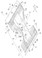
- FIG. 1 shows a perspective view of an adult disposable pull-on diaper 10 shown as an example of an embodiment of the present invention.
- the diaper 10 is suitable for a male incontinence patient to wear, and includes a torso cover 1 and an absorbent chassis 2 (see FIG. 2) attached to the torso cover 1.
- the torso cover 1 has at least the front waist region and the rear waist region among the front waist region, the rear waist region, and the crotch region as essential elements.
- the front waist region 3, the rear waist region 4 An example including a crotch region 5 is shown.
- the front waist region 3 and the rear waist region 4 are joined to each other by attaching a series of seams 9 by ultrasonic treatment at their side edges 7 and 8, and a waist region 11 taking an annular shape when the diaper 10 is worn.
- a waist opening 12 and a pair of leg openings 13 are defined.
- the torso cover 1 includes a front outer surface sheet 16 extending to the front waist region 3 and a part of the crotch region 5, a rear outer surface sheet 17 extending to the rear waist region 4 and a part of the crotch region 5, and a central outer surface extending to the crotch region 5.
- Sheet 18 In the figure, the horizontal direction of the diaper 10 is indicated by X, and the vertical direction is indicated by Y.
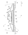
- FIG. 2 this is the inner side of the diaper 10 in FIG. 1 where the front waist region 3 and the rear waist region 4 are joined and the diaper 10 is extended in the horizontal and vertical directions X and Y.
- the partial fracture perspective view shown is shown.
- the torso cover 1 is formed in an almost hourglass shape and extends to the front waist region 3, the rear waist region 4, and the crotch region 5, and the front outer sheet joined to the central outer sheet 18 from the outside of the diaper 10.
- 16 and a rear outer sheet 17 that is similarly joined to the central outer sheet 18 from the outside (see FIG. 1).
- Between the front outer sheet 16 and the central outer sheet 18, a plurality of front waist elastic members 21 extending in the lateral direction X so as to be contractible are interposed.
- a plurality of rear waist elastic members 22 extending in the lateral direction X so as to be contractible are interposed between the rear outer sheet 17 and the central outer sheet 18.
- a plurality of leg elastic members 23 extending in the lateral direction X are drawn between the rear outer sheet 17 and the central outer sheet 18 so as to form a convex curve toward the front waist region 3. It is interposed in a contracted state.
- a part of the front outer sheet 16 and the rear outer sheet 17 are folded back to the inner surface side of the diaper 10 at the edge 3a of the front waist region 3 and the edge 4a of the rear waist region 4.
- the folded portions 16a and 17a are indicated by phantom lines, and the portions 16a and 17a in a state before being folded are indicated by solid lines.
- the absorbent chassis 2 extends from the crotch region 5 of the torso cover 1 to the front waist region 3 and the rear waist region 4, and a front end region in which a part is joined to the front waist region 3. 26, a rear end region 27 partially joined to the rear waist region 4, and an intermediate portion 28 partially joined to the crotch region 5.
- the absorbent chassis 2 also includes an absorbent structure 31 having a rectangular planar shape and a pair of containment cuffs 32 positioned on both sides of the absorbent structure 31 in the lateral direction X.
- one of the containment cuffs 32 is indicated by a solid line, but the other is indicated by a virtual line.
- the edges located on both sides in the lateral direction X define the leg openings 3.
- the containment cuff 32 includes a proximal edge 33 fixed to the absorbent structure 31, and a distal edge 34 that is not joined to the absorbent structure 31 in the crotch region 5 and is separable. And one or more elastic members 36 functioning as a spacer are attached to the distal edge 34 so as to be contracted in an extended state.
- the distal edge 34 is fixed to the front end region 26 and the rear end region 27 of the absorbent structure 31.
- FIG. 3 shows a cut surface along the line S 3 of the absorbent chassis 2.
- 4 shows a cut surface along the lines S 2 and S 4 of the absorbent chassis 2
- FIG. 5 shows a cut surface along the lines S 1 and S 5 of the absorbent chassis 2.
- the absorbent structure 31 in the absorbent chassis 2 includes a core material 41 that is an aggregate of liquid-absorbing materials including at least pulverized pulp and highly water-absorbing polymer particles, and a liquid-permeable wrapping sheet 42 that covers the core material 41.
- the absorbent body 40 formed by the above, a liquid-permeable body-side liner 43 covering the inner surface side of the core material 41 through the wrapping sheet 42, and the outer surface side of the core material 41 through the wrapping sheet 42 Liquid impervious backsheet 44.
- the core material 41 is a bonding region where the entire outer surface 41b facing the central outer sheet 18 that is the inner surface 41a of the torso cover 1 is bonded to the wrapping sheet 42 via, for example, a hot melt adhesive HA. Further, the inner surface 41a, which is the opposite surface of the outer surface 41b, of the core material 41 serves as a joining region where the inner surface 41a is joined to the wrapping sheet 42 on both the center line P and the both sides of the center line P. 42 is a non-bonded area.
- the mass per unit area is in the range of 300-600 g / m 2 and the amount of pulp Is preferably in the range of 60-40% by weight, and the amount of the superabsorbent polymer particles is preferably in the range of 40-60% by weight.
- 300 g / m 2 of pulp and 200 g / m 2 of superabsorbent polymer particles can be used in a uniformly mixed state or in a state where layers overlapping each other are formed,
- the core material 41 can also be used in a state in which the distribution amount of the superabsorbent polymer particles is different in the lateral direction X and the front-rear direction Z.
- the superabsorbent polymer particles those conventionally used in the art, for example, a hydrolyzate of starch-acrylonitrile copolymer can be used.
- the core material 41 can also be formed by mixing a liquid-absorbing material using an air flow and depositing it inside a mold having a required shape. It can also be used under pressure compression.
- tissue paper, liquid permeable nonwoven fabric, or the like can be used for the wrapping sheet 42.
- the wrapping sheet 42 is in a state of being bonded to the outer surface 41b of the core material 41 via, for example, a hot melt adhesive HA, and a portion extending laterally from the core material 41 is wound around the core material 41.
- the side portions 42a and 42b of the wrapping sheet 42 overlap each other on both sides of the center line P that covers the inner surface 41a of the core material 41 and bisects the lateral dimension of the absorbent chassis 2, for example, hot melt adhesive HA And are also bonded to the core material 41.
- a portion where the core material 41 is bonded to the wrapping sheet 42 via the hot melt adhesive HA is a bonding region of the liquid absorbent material aggregate to the wrapping sheet 42.
- the overlapping side portions 42a and 42b are covered with a liquid-permeable cover sheet 45, thereby preventing the liquid-absorbing material from leaking out between the side portions 42a and 42b.
- the cover sheet 45 is bonded to the wrapping sheet 42 via, for example, a hot melt adhesive HA.
- Such a core material 41 and the wrapping sheet 42 are in close contact with each other at both side portions 46 of the core material 41, but are not joined. Further, the overlapping wrapping sheets 42 located on the outer side of the core material 41 in the lateral direction X are joined to each other via, for example, a hot melt adhesive HA. Accordingly, the entire outer surface 41b of the core member 41 is fixed to the wrapping sheet 42, and only the both side portions of the center line P of the inner surface 41a are fixed to the wrapping sheet 42. 41a is not covered by the hot melt adhesive.
- the absorption of the body fluid through the wrapping sheet 42 is not hindered by the hot melt adhesive, and the pulverized pulp and the superabsorbent polymer particles forming the inner surface 41a are not disturbed. Movement, for example, the movement of the superabsorbent polymer particles to swell, is not hindered by the presence of hot melt adhesive.
- the absorbent body 40 in which the superabsorbent polymer particles can freely swell without being obstructed by their surroundings can have a high body fluid absorption rate and a large amount of absorption per unit time.
- the body side liner 43 is formed of a nonwoven fabric or an open plastic film using a thermoplastic synthetic fiber.
- the back sheet 44 is formed of a plastic film, more preferably a gas permeable plastic film.
- the body-side liner 43 and the back sheet 44 are bonded to each other at, for example, a hot melt adhesive (not shown).
- the body side liner 43 can be joined to the wrapping sheet 42 via, for example, a hot melt adhesive (not shown) in an appropriate application state such as spiral, dot, or stripe.
- the containment cuff 32 has a proximal edge 33 bonded to the body side liner 43 and the back sheet 44 in the absorbent structure 31 via, for example, a hot melt adhesive (not shown).
- the distal edge 34 to which the elastic member 36 is attached is in a state of being superimposed on the body side liner 43 in FIG. 2, but in order to clearly show the distal edge 34 in FIG. Is shown spaced apart from When the diaper 10 is in the state shown in FIG. 1, the elastic member 36 contracts between the front end region 26 and the rear end region 27 of the absorbent structure 31, so that the distal edge 34 is indicated by an imaginary line. It will be in the state which protruded on the absorptive structure 31, and will exhibit the function as a cuff which prevents the side leakage of excrement.
- FIG. 4 shows lines S 2 and S that traverse each of the front end region 26 and the rear end region 27 that overlap the front waist region 3 and the rear waist region 4 of the torso cover 1 in the absorbent structure 31.
- it is a diagram showing a cut surface taken along the 4, but with the cutting plane and the line S 4 along the cutting plane taken along the line S 2, is the same in real sense.
- the cut surface in FIG. 4 and the cut surface in FIG. 3 are compared, although the dimension of the horizontal direction X of the substantially rectangular absorbent structure 31, ie, the width, is the same, in FIG.
- the structure 31 extends over the entire width, and there is no overlapping portion of the wrapping sheets 42 outside the core material 41. That is, the width of the core material 41 of FIG.
- both side portions 46 of the core material 41 in the non-bonded state with respect to the wrapping sheet 42 are both side portions in FIG. 3.
- the dimension in the lateral direction X is larger than 46.
- the attachment state of the containment cuff 32 to the absorbent structure 31 is the same as that of FIG.
- the front outer sheet 16 or the rear outer sheet 17 is bonded to the central outer sheet 18 bonded to the back sheet 44 from the outside of the diaper 10 via, for example, a hot melt adhesive (not shown).
- FIG. 5 shows a cut surface along lines S 1 and S 5 crossing a portion that does not include the core material 41 in the front end region 26 and the rear end region 27 of the absorbent structure 31. ing. However, the state of the cut surface along each of these lines S 1 and S 5 is substantially the same.
- the wrapping sheets 42 extending from the core material 41 in the longitudinal direction Y are joined to each other via, for example, a hot melt adhesive HA, and the body side liner 43 and the back sheet 44 are overlapped with each other. For example, it joins via a hot-melt-adhesive (not shown).
- the back sheet 44, the center outer sheet 18, and the front outer sheet 16 or the rear outer sheet 17 overlap each other and are joined to each other through, for example, a hot melt adhesive (not shown). Further, the distal edge 34 of the containment cuff 32 overlaps the body side liner 43 and is joined to the body side liner 43 through, for example, a hot melt adhesive (not shown).
- FIG. 6 is a diagram showing a cut surface of the absorbent structure 31 along the line S 0 in FIG. 2, line S 0 is aligned with the center line P in FIG.
- the wrapping sheet 42, the cover sheet 45, and the body side liner 43 extend from the core material 41, overlap each other, and are joined via, for example, a hot melt adhesive HA.
- the body side liner 43 and the back sheet 44 overlap at a portion extending from the wrapping sheet 42, and are joined to each other via, for example, a hot melt adhesive (not shown).
- the central outer sheet 18 and the front outer sheet 16 that are joined to each other and the central outer sheet 18 and the rear outer sheet 17 that are joined to each other extend from the back sheet 44.
- a portion 16a in which the front outer sheet 16 extends from the central outer sheet 18 and a portion 17a in which the rear outer sheet 17 extends from the central outer sheet 18 are folded along the edge of the central outer sheet 18 to be the central outer sheet. 18 and the absorptive structure 31 and are bonded via, for example, a hot melt adhesive (not shown).
- the front outer sheet 16 and the rear outer sheet 17 are folded back to form the edges 3a and 4a of the waist opening 12 of the diaper 10 (see FIG. 1).
- Waist elastic members 21 and 22 are interposed between the overlapping central outer sheet 18 and the front outer sheet 16 and between the overlapping central outer sheet 18 and the rear outer sheet 17.
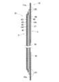
- FIG. 7 is a diagram showing a procedure for forming the absorbent structure 31 from the core material 41 and the wrapping sheet 42.
- FIG. 7A shows a substantially hourglass-shaped core member 41 and a rectangular wrapping sheet 42.
- the core member 41 is formed with wings 51 so that the width of the portion 41d located in the crotch region 5 of the torso cover 1 is narrow and the portions located in the front waist region 6 and the rear waist region 7 are wide. .
- a portion that contacts the lower surface 41 b (see FIG. 3) of the core member 41 is indicated by an imaginary line 52. Further, a portion where the hot melt adhesive HA is applied is indicated by a large number of dots 53.
- the wrapping sheet 42 is also formed with a non-application site 54 where the hot melt adhesive HA is not applied.
- the core material 41 and the wrapping sheet 42 are symmetrical with respect to the center line P.
- FIG. 2B shows an absorbent structure 31 formed by covering the core material 41 with the wrapping sheet 42, and the absorbent structure 31 is overlapped with the wrapping sheet 42 on the center line P.
- the position of the cover sheet 45 to be applied is indicated by a virtual line.
- the core material 41 is placed on the wrapping sheet 42, and both side portions of the wrapping sheet are overlapped on the inner surface 41a of the core material 41, whereby the absorbent structure 31 of (b) is formed.
- both side portions 46 where the portion overlapping the non-application area 54 of the wrapping sheet 42 is not bonded to the wrapping sheet 42 ( (See FIG. 3).
- the side portions 46 include side portions of the portion 41 d located in the crotch region 5 and wing portions 51.
- the outer surface 41 b of the core material 41 is fixed to the wrapping sheet 42 by the hot melt adhesive HA, and the wrapping sheet 42 and the hot melt adhesive HA are attached to the periphery of the core material 41. Since the wrapping sheets 42 that are joined to each other are in close contact with each other, the core material 41 does not move in the lateral direction X or the front-rear direction Z inside the absorbent structure 31.
- the core 41 has a central portion in the lateral direction X bonded to the wrapping sheet 42 via, for example, a hot melt adhesive HA. Even if it exists, it does not move to the horizontal direction X or the vertical direction Y, and the core material 41 becomes a thing which does not lose shape easily. Therefore, in the diaper 10, the absorbent chassis 2 does not become difficult for the diaper 10 to fit the wearer's skin due to the deformation of the core material 41. On the other hand, in the core material 41, the inner surface 41a of the side portion 46 is not joined to the wrapping sheet 42, so that rapid absorption of body fluid through the wrapping sheet 42 is hindered by the hot melt adhesive. There is no.
- the movement of the superabsorbent polymer particles in the thickness direction, the transverse direction X, and the longitudinal direction Y of the core material 41 is not hindered by the hot melt adhesive.
- the water-absorbing polymer particles can easily exhibit the water-absorbing ability without the swelling of the highly water-absorbing polymer particles accompanying water absorption being hindered by the hot melt adhesive.
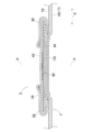
- FIG. 8 and 9 respectively show a partially broken plan view of the absorbent structure 31 showing an example of the embodiment and a sectional view taken along the line IX-IX in the plan view.
- a plurality of compressed grooves 61 are formed on the core material 41 and the wrapping sheet 42, and the compressed grooves 61 are covered with a cover sheet 45.
- the pressing groove 61 is formed by locally pressing the core material 41 and the wrapping sheet 42 in the direction from the inner surface 41a of the core material 41 toward the outer surface 41b.
- the bottom 61 a of the compressed groove 61 is in a state where a liquid-absorbing material such as pulverized pulp is compressed, and the density of the core material 41 at the bottom 61 a is higher than the density of the core material 41 in the peripheral area of the compressed groove 61.
- a preferable compressed groove 61 is formed so as to be symmetric with respect to the center line P at a portion where the core material 41 and the wrapping sheet 42 are joined via the hot melt adhesive HA.
- the compressed groove 61 is preferably formed in the crotch region 5 between the front waist region 3 and the rear waist region 4 in the torso cover 1. Furthermore, when only one pair of compressed groove 61 is formed, it is preferable that the compressed groove is formed in the front portion of the crotch region 5.
- the pair of squeezed grooves 61 formed in the front portion of the crotch region 5 is absorbent when the diaper 10 is worn so that the male genitalia fit between them.
- the chassis 2 fits well to the body, and the diaper 10 is comfortable to wear.
- the cover sheet 45 in the absorbent structure 31 prevents the occurrence of a problem that liquid-absorbing materials such as pulverized pulp and highly water-absorbing polymer particles leak out from the ruptures of the wrapping sheet 42 and the wrapping sheet 42 and come into contact with the skin. Can do.
- a torso cover that has a lateral direction and a longitudinal direction, and forms an annular shape by forming at least the front waist region and the rear waist region of a front waist region, a rear waist region, and a crotch region;
- An absorbent chassis including an absorbent structure, a waist opening, and a pair of waist openings, each having a front end region and a rear end region that extend between the front waist region and the rear waist region and are respectively joined to the front waist region and the rear waist region.
- a disposable pull-on diaper including a leg opening of
- the absorbent chassis includes an absorber included in the absorbent structure, and the absorber is a liquid-permeable core material that is an aggregate of liquid-absorbing materials including at least pulverized pulp and highly water-absorbing polymer particles.
- the joining area extends in the longitudinal direction at the central portion in the lateral direction of the assembly, and the non-joining area is located on both sides of the joining area in the lateral direction. It is characterized by.
- the disposable pull-on diaper according to the present invention arranged as the above matter includes at least the following embodiments, and the embodiments can be adopted separately or in combination with each other.
- the wrapping sheet covers the inner surface of the assembly by folding back a portion in which the wrapping sheet covering the outer surface of the assembly extends in the lateral direction from the assembly. In the central portion of the inner surface, the folded wrapping sheets overlap each other and are bonded to each other via an adhesive.
- the assembly has a substantially hourglass shape in plan view, and the front end region and the rear end region are formed with wings extending on both sides in the lateral direction, and the inner surface of the wing portion is It forms part of the non-bonded area.
- the absorbent body extends in the longitudinal direction so as to face each other in the lateral direction, and is formed with at least a pair of compressed grooves that are deeper from the inner surface toward the outer surface. Located in the area.
Landscapes
- Health & Medical Sciences (AREA)
- Epidemiology (AREA)
- Engineering & Computer Science (AREA)
- Biomedical Technology (AREA)
- Heart & Thoracic Surgery (AREA)
- Vascular Medicine (AREA)
- Life Sciences & Earth Sciences (AREA)
- Animal Behavior & Ethology (AREA)
- General Health & Medical Sciences (AREA)
- Public Health (AREA)
- Veterinary Medicine (AREA)
- Absorbent Articles And Supports Therefor (AREA)
- Orthopedics, Nursing, And Contraception (AREA)
Abstract
吸収体におけるラッピングシートの体液透過性が改良された使い捨てプルオンおむつの提供。 使い捨てプルオンおむつにおける吸収性シャシー(2)が吸収体(40)を含んでいる。吸収体(40)は、粉砕パルプと高吸水性ポリマー粒子とを含む吸液性材料の集合体である芯材(41)をラッピングシート(42)で被覆することによって形成され、芯材(41)は、その外面(41b)の全体が接着剤(HA)を介してラッピングシート(42)に接合する。芯材(41)の内面(41a)は、ラッピングシート(42)に対する接合域と非接合域とを有する。接合域は芯材(41)の横方向の中央部に形成され、非接合域の両側に形成されている。
Description
この開示は、使い捨てプルオンおむつに関し、より詳しくは吸収体の芯材が粉砕パルプと高吸水性ポリマー粒子とを含む使い捨てプルオンおむつに関する。
従来、使い捨てプルオンおむつは周知であり、吸収体の芯材が粉砕パルプと高吸水性ポリマー粒子とを含む使い捨てプルオンおむつも周知である。
例えば、特開2001-120594号公報(特許文献1)に記載された使いすておむつは、吸収体の型くずれの防止を課題とするものであって、そのおむつの一例では、吸収体が薄葉紙に包まれていて、吸収体と薄葉紙とが接着剤により固定されている。吸収体は、薄葉紙を介しておむつ着用者の肌と向かい合う内面の全体に塗布された接着剤を介して薄葉紙に固定されている.吸収体の外面は接着剤が塗布されておらず、薄葉紙に対して非接合状態にある。吸収体は綿状パルプや高吸水性高分子物質等で形成されている。
パルプや高吸水性ポリマー等の吸液性材料の集合体を薄葉紙等のラッピングシートで被覆することにより形成されている吸収体では、その集合体の内外面のうちでおむつ着用者の肌と向かい合う側に位置する内面が、その全体に塗布された接着剤を介してラッピングシートに接合されると、ラッピングシートに対する体液の速やかな透過の妨げになったり、それに伴って吸液性材料の集合体による体液の速やかな吸収の妨げになったりするということがある。
この発明では、吸液性材料の集合体を透液性のラッピングシートで被覆することにより形成されている吸収体で生じるそのような問題を解消することが可能な使い捨てプルオンおむつの提供を課題にしている。
前記課題を解決するための、この発明は、横方向と縦方向とを有し、前ウエスト域と後ウエスト域とクロッチ域とのうちの少なくとも前記前ウエスト域と前記後ウエスト域とを形成していて環状形をとることが可能なトルソカバーと、前記前ウエスト域と前記後ウエスト域との間に延びていてそれらにそれぞれに接合する前端域と後端域とを有し、吸収性構造体を含む吸収性シャシーと、ウエスト開口と、一対のレッグ開口とを含む使い捨てプルオンおむつである。
この発明は、さらに下記を含む。すなわち、前記吸収性シャシーは、前記吸収性構造体に含まれる吸収体を含み、前記吸収体は少なくとも粉砕パルプと高吸水性ポリマー粒子とを含む吸液性材料の集合体である芯材を透液性のラッピングシートで被覆することにより形成されている。前記集合体は、前記トルソカバーの内面と向かい合う外面の全体が接着剤を介して前記ラッピングシートに接合する一方、前記外面の反対面である前記集合体の内面は前記ラッピングシートに対する接合域と非接合域とを有し、前記接合域は前記集合体における前記横方向の中央部分において前記縦方向へ延びており、前記非接合域は、前記横方向において前記接合域の両側に位置している。
本明細書における用語「プルオンおむつ」は、ウエスト開口および一対のレッグ開口を有し、着用者のレッグをレッグ開口に挿入して着用者のウエストまで引き上げて着用する物品を指す。用語「使い捨て」は通常、単に一回の使用で廃棄が意図されていることを指す。
この発明の一つ以上の実施形態に係る使い捨てプルオンおむつでは、吸液性の芯材の外面がラッピングシートに接合され、芯材の内面にはラッピングシートに対する非接合域が形成されるから、その非接合域においてはラッピングシートを介しての体液の速やかな吸収が可能になる。
図面は、この発明の特定の実施形態を示し、発明の不可欠な構成ばかりでなく、選択的及び好ましい実施形態を含む。
使い捨てプルオンおむつの斜視図。
おむつの両側縁部のシームを解いて縦横方向に伸展した部分破断斜視図。
図2の線S3に沿う切断面を示す図。
図2の線S2に沿う切断面を示す図。
図2の線S1に沿う切断面を示す図。
図2の線S0に沿う切断面を示す図。
吸収性構造体の作成手順を示す図。
実施態様の一例を示す吸収性構造体の部分破断平面図。
図8のIX-IX線に沿う切断面を示す図。
添付の図面を参照して、この発明に係る使い捨てプルオンおむつの詳細を説明すると、以下のとおりである。下記の実施形態は、図1~9に示すおむつに関し、発明の不可欠な構成ばかりでなく、選択的及び好ましい構成を含む。
図1を参照すると、これは、この発明の実施形態の一例として示す大人用の使い捨てプルオンおむつ10の斜視図を示す。おむつ10は、男性の失禁患者が着用するのに好適であって、トルソカバー1と、トルソカバー1に取り付けられている吸収性シャシー2(図2参照)とを含む。トルソカバー1は、前ウエスト域と後ウエスト域とクロッチ域とのうちの少なくとも前ウエスト域と後ウエスト域とを不可欠要素とするところ、図には、前ウエスト域3と、後ウエスト域4と、クロッチ域5とを含む例が示されている。前ウエスト域3と後ウエスト域4とは、それらの側縁7,8において、超音波処理によって一連のシーム9を付けることで互いに接合され、おむつ10の着用時に環状形をとるウエスト域11が形成されるとともに、ウエスト開口12と一対のレッグ開口13とが画定されている。トルソカバー1は、前ウエスト域3とクロッチ域5の一部分とに延びる前方外面シート16と、後ウエスト域4とクロッチ域5の一部とに延びる後方外面シート17と、クロッチ域5に延びる中央外面シート18とを含む。図には、おむつ10の横方向がXで、縦方向がYで示されている。
図2を参照すると、これは、図1のおむつ10において前ウエスト域3と後ウエスト域4とが接合するシーム9を解いておむつ10を横縦方向X,Yに伸展した状態の内面側を示す部分破断斜視図を示す。トルソカバー1はほぼ砂時計型に形成されていて前ウエスト域3と後ウエスト域4とクロッチ域5とに延びる中央外面シート18と、おむつ10の外側から中央外面シート18に接合している前方外面シート16と、同じように外側から中央外面シート18に接合している後方外面シート17とを含む(図1参照)。前方外面シート16と中央外面シート18との間には、横方向Xへ伸長状態で収縮可能に延びる複数条の前方ウエスト弾性部材21が介在している。同様に、後方外面シート17と中央外面シート18との間には、横方向Xへ伸長状態で収縮可能に延びる複数条の後方ウエスト弾性部材22が介在している。また、後方外面シート17と中央外面シート18との間には、前ウエスト域3に向かって凸となる曲線を画いて横方向Xへ延びる複数条のレッグ弾性部材23が少なくとも部分的に伸長された状態で収縮可能に介在している。なお、図1において、前方外面シート16と後方外面シート17とは、それらの一部分が前ウエスト域3の縁部3aと後ウエスト域4の縁部4aとにおいておむつ10の内面側に折り返されているところ、図2においては、その折り返されている部分16a,17aが仮想線で示され、折り返される前の状態にある部分16a,17aが実線で示されている。
図2から明らかなように、吸収性シャシー2は、トルソカバー1のクロッチ域5から前ウエスト域3と後ウエスト域4とにまで延びていて、一部分が前ウエスト域3に接合している前端域26と、一部分が後ウエスト域4に接合している後端域27と、一部分がクロッチ域5に接合している中間部28とを有する。吸収性シャシー2はまた、平面形状が矩形に形成されている吸収性構造体31と、横方向Xにおいて吸収性構造体31の両側に位置する一対の封じ込めカフス32とを含む。ただし、図2において、封じ込めカフス32の一方は実線で示されているが、もう一方は仮想線で示されている。クロッチ域5は、横方向Xの両側に位置する縁部がレッグ開口3を画定している。
封じ込めカフス32は、吸収性構造体31に固定されている近位縁部33と、クロッチ域5において吸収性構造体31に接合しておらず、離間可能な状態にある遠位縁部34とを有し、遠位縁部34にはスペサーとして機能する一条または複数条の弾性部材36が伸長状態で収縮可能に取り付けられている。かかる遠位縁部34は、吸収性構造体31の前端域26と後端域27とに固定されている。このように形成されている封じ込めカフス32は、おむつ10が図1の状態にあるときには、弾性部材36が収縮することによって、おむつ10の少なくともクロッチ域5においては遠位縁部34が吸収性構造体31から着用者に向かって離間し、封じ込めカフス32のそれぞれが吸収性構造体31に対して起立した状態になる。
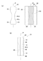
図3,4,5を参照すると、これらは、図2に示すおむつ10における吸収性シャシー2の切断面を示す図であって、図3は吸収性シャシー2の線S3に沿う切断面を示し、図4は吸収性シャシー2の線S2,S4に沿う切断面を示し、図5は吸収性シャシー2の線S1,S5に沿う切断面を示している。
図3において、線S3は図2のおむつ10における前後方向の寸法を二等分する中心線Qに一致している。吸収性シャシー2における吸収性構造体31は、少なくとも粉砕パルプと高吸水性ポリマー粒子とを含む吸液性材料の集合体である芯材41および芯材41を被覆する透液性のラッピングシート42によって形成される吸収体40と、ラッピングシート42を介して芯材41の内面側を被覆している透液性の身体側ライナー43と、ラッピングシート42を介して芯材41の外面側を被覆している不透液性のバックシート44とを含む。芯材41は、トルソカバー1の内面41aである中央外面シート18と向かい合っている外面41bの全体が例えばホットメルト接着剤HAを介してラッピングシート42に接合する接合域になっている。また、芯材41は外面41bの反対面である内面41aが中心線Pの上と中心線Pの両側部分においてもラッピングシート42に接合する接合域となり、芯材41の両側部分46がラッピングシート42に対する非接合域になっている。芯材41は、それが軽失禁用のものであってパルプと高吸水性ポリマー粒子とで形成される場合、単位面積当たりの質量が300-600g/m2の範囲にあって、パルプの量が60-40重量%の範囲にあり、高吸水性ポリマー粒子の量が40-60重量%の範囲にあることが好ましい。具体的な一例として、300g/m2のパルプと200g/m2の高吸水性ポリマー粒子とが、均一に混合された状態や互いに重なり合った層を形成した状態で使用することができる他に、芯材41の横方向Xや前後方向Zにおいて高吸水性ポリマー粒子の分布量が異なる状態で使用することもできる。高吸水性ポリマー粒子には、当該技術分野において慣用のもの、例えばデンプン-アクリロニトリル共重合体の加水分解物等を使用することができる。芯材41はまた、吸液性材料を空気流を利用して混合し所要形状の型の内部に堆積させることによって成形したものを使用することができる他に、堆積させたものに散水してからそれを加圧圧縮して使用することもできる。
ラッピングシート42には、ティッシュペーパや透液性の繊維不織布等を使用することができる。ラッピングシート42は、芯材41の外面41bに対して例えばホットメルト接着剤HAを介して接合した状態にあって、その芯材41から側方へ延出する部分が芯材41に巻き付けられて芯材41の内面41aを覆い、吸収性シャシー2の横方向の寸法を二等分している中心線Pの両側においてラッピングシート42の側部42a,42bどうしが重なり合い、例えばホットメルト接着剤HAを介して互いに接合するとともに芯材41に対しても接合している。芯材41がホットメルト接着剤HAを介してラッピングシート42に接合している部位は、吸液性材料の集合体のラッピングシート42に対する接合域である。
好ましい芯材41では、重なり合う側部42a,42bが透液性のカバーシート45によって覆われていて、側部42aと42bとの間から吸液性材料の漏れ出ることを防止している。そのカバーシート45は、例えばホットメルト接着剤HAを介してラッピングシート42に接合している。
このような芯材41とラッピングシート42とは、芯材41の両側部分46において互いに密着してはいるが、非接合状態にある。また、横方向Xにおいて芯材41の外側に位置して重なり合うラッピングシート42どうしは、例えばホットメルト接着剤HAを介して互いに接合している。したがって、芯材41は、その外面41bの全体がラッピングシート42に対して固定されるとともに、内面41aは中心線Pの両側部分のみがラッピングシート42に固定されているが、両側部分46における内面41aはホットメルト接着剤によって覆われることがない。したがって、両側部分46の内面41aでは、ラッピングシート42を介しての体液の吸収がホットメルト接着剤によって妨げられることがなく、また、内面41aを形成している粉砕パルプや高吸水性ポリマー粒子の動き、例えば高吸水性ポリマー粒子が膨潤しようとする動きはホットメルト接着剤の存在によって妨げられるということがない。このように高吸水性ポリマー粒子がその周囲によって妨げられることなく自由に膨潤することができる吸収体40は、体液の吸収速度が速く、単位時間当たりの吸収量が多いものになり得る。
身体側ライナー43とバックシート44とにおいて、身体側ライナー43は、熱可塑性合成繊維を使用した不織布や開孔プラスチックフィルムで形成されている。バックシート44は、プラスチックフィルム、より好ましくは通気透液性のプラスチックフィルムによって形成されている。身体側ライナー43とバックシート44とは、互いに重なり合う部分において例えばホットメルト接着剤(図示せず)を介して接合している。身体側ライナー43は、スパイラル状やドット状、ストライプ状等の適宜の塗布状態にある例えばホットメルト接着剤(図示せず)を介してラッピングシート42に接合することができる。
封じ込めカフス32は、近位縁部33が例えばホットメルト接着剤(図示せず)を介して吸収性構造体31における身体側ライナー43とバックシート44とに接合している。弾性部材36が取り付けられている遠位縁部34は、図2において身体側ライナー43に重なる状態にあるものであるが、図3では遠位縁部34を明示するために、身体側ライナー43から離間した状態で示されている。おむつ10が図1の状態にあるときには、吸収性構造体31における前端域26と後端域27との間において弾性部材36が収縮することによって、遠位縁部34は仮想線で示されるように吸収性構造体31上に突出した状態になり、排泄物の横漏れを防止するカフとしての機能を発揮する。
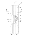
図4は、吸収性構造体31のうちで、トルソカバー1における前ウエスト域3と後ウエスト域4とのそれぞれに重なっている前端域26と後端域27のそれぞれを横断する線S2,S4に沿う切断面を示す図であるが、線S2に沿う切断面と線S4沿う切断面とは、実質的な意味において同じである。また、図4における切断面と図3における切断面とを比較すると、ほぼ矩形の吸収性構造体31の横方向Xの寸法、即ち幅は同じであるが、図4では芯材41が吸収性構造体31の幅全体に広がっていて、芯材41の外側にはラッピングシート42どうしの重なり合う部分がない。すなわち、図4の芯材41は、その幅が図3のそれよりも大きく、それに伴って、ラッピングシート42に対して非接合状態にある芯材41の両側部分46は、図3における両側部分46よりも横方向Xにおける寸法が大きくなっている。封じ込めカフス32の吸収性構造体31に対する取り付け状態は、図3のそれと同じである。なお、バックシート44に接合している中央外面シート18には、おむつ10の外側から前方外面シート16または後方外面シート17が例えばホットメルト接着剤(図示せず)を介して接合している。
図5は、吸収性構造体31の前端域26と後端域27とのうちで、芯材41を含むことのない部位を横断している線S1とS5とに沿う切断面を示している。ただし、これらの線S1,S5のそれぞれに沿う切断面の状態は、実質的に同じである。図5では、縦方向Yにおいて芯材41から延出しているラッピングシート42が互いに例えばホットメルト接着剤HAを介して接合し、身体側ライナー43とバックシート44とがそれらと重なり合うラッピングシート42に対して例えばホットメルト接着剤(図示せず)を介して接合している。バックシート44と、中央外面シート18と、前方外面シート16または後方外面シート17とは、互いに重なり合って例えばホットメルト接着剤(図示せず)を介して互いに接合している。また、封じ込めカフス32の遠位縁部34は、身体側ライナー43に重なり例えばホットメルト接着剤(図示せず)を介してその身体側ライナー43に接合している。
図6を参照すると、これは、図2の線S0に沿う吸収性構造体31の切断面を示す図であり、線S0は図2の中心線Pに一致している。吸収性構造体31では、ラッピングシート42とカバーシート45と身体側ライナー43とが芯材41から延出して、互いに重なり合って例えばホットメルト接着剤HAを介して接合している。身体側ライナー43とバックシート44とはラッピングシート42から延出する部分において重なり合い、例えばホットメルト接着剤(図示せず)を介して互いに接合している。互いに接合している中央外面シート18と前方外面シート16、および互いに接合している中央外面シート18と後方外面シート17は、バックシート44から延出している。前方外面シート16が中央外面シート18から延出する部分16aと後方外面シート17が中央外面シート18から延出する部分17aとは、中央外面シート18の縁部に沿って折り返されて中央外面シート18と吸収性構造体31とに重なるとともに例えばホットメルト接着剤(図示せず)を介して接合されている。前方外面シート16と後方外面シート17とは、そのように折り返されることによっておむつ10のウエスト開口12の縁部3a,4aを形成している(図1参照)。重なり合う中央外面シート18と前方外面シート16との間、および重なり合う中央外面シート18と後方外面シート17との間には、ウエスト弾性部材21,22が介在している。
図7は、芯材41とラッピングシート42とから吸収性構造体31を形成する手順を示す図である。図7の(a)には、ほぼ砂時計型の芯材41と、矩形のラッピングシート42とが示されている。芯材41は、トルソカバー1のクロッチ域5に位置する部分41dの幅が狭く、前ウエスト域6と後ウエスト域7とに位置する部分は幅が広くなるように翼部51が形成されている。ラッピングシート42には、芯材41の下面41b(図3参照)と接触する部位が仮想線52で示されている。また、ホットメルト接着剤HAの塗布されている部位が多数のドット53によって示されている。ラッピングシート42にはまた、ホットメルト接着剤HAの塗布されることのない非塗布部位54が形成されている。芯材41とラッピングシート42とは、中心線Pに関して対称なものである。
図の(b)には、芯材41をラッピングシート42で被覆することにより形成された吸収性構造体31が示され、吸収性構造体31には、中心線P上においてラッピングシート42に重ねられるカバーシート45の位置が仮想線で示されている。(a)において芯材41がラッピングシート42に載せられて、ラッピングシートの両側部分が芯材41の内面41aに重ねられることによって(b)の吸収性構造体31が形成される。吸収性構造体31における芯材41では、図3,4に示されているように、ラッピングシート42における非塗布域54と重なる部分がラッピングシート42に対して接合することのない両側部分46(図3参照)となる。両側部分46には、クロッチ域5に位置する部分41dにおける側方部分と、翼部51とが含まれている。吸収性構造体31では、芯材41の外面41bがホットメルト接着剤HAによってラッピングシート42に固定されていることに加え、芯材41の周縁に対してはラッピングシート42やホットメルト接着剤HAを介して互いに接合しているラッピングシート42が密着しているから、芯材41は吸収性構造体31の内部において横方向Xや前後方向Zに動くことがない。
芯材41はまた、外面41bの全体がラッピングシート42に接合していることに加えて、内面41aは横方向Xの中央部分が例えばホットメルト接着剤HAを介してラッピングシート42に接合していることによっても、横方向Xや縦方向Yに動くことがなく、芯材41は型崩れしにくいものになる。それゆえ、おむつ10では、芯材41の型崩れによって吸収性シャシー2がおむつ10が着用者の肌部にフィットし難くなるということがない。一方、芯材41は、側部46における内面41aがラッピングシート42に対して非接合状態にあることによって、ラッピングシート42を介しての体液の速やかな吸収がホットメルト接着剤によって妨げられるということがない。さらにはまた、その側部46における内面41aでは、芯材41の厚さ方向や横方向X、縦方向Yへの高吸水性ポリマー粒子の動きがホットメルト接着剤によって妨げられるということがないので、吸水に伴う高吸水性ポリマー粒子の膨潤がホットメルト接着剤によって妨げられるということもなく、高吸水性ポリマー粒子の吸水能力の発揮が容易になる。
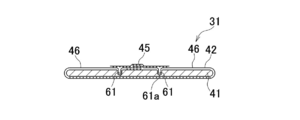
図8,9を参照すると、これらはそれぞれ、実施態様の一例を示す吸収性構造体31の部分破断平面図と、その平面図におけるIX-IX線断面図を示す。図示例の吸収性構造体31には、芯材41とラッピングシート42とに対して複数の圧搾条溝61が形成されていて、その圧搾条溝61がカバーシート45によって覆われている。圧搾条溝61は、芯材41とラッピングシート42とが芯材41の内面41aから外面41bへ向かう方向へ局部的に圧搾されることで形成されている。圧搾条溝61の底部61aでは粉砕パルプ等の吸液性材料が圧縮された状態にあり、底部61aにおける芯材41の密度は圧搾条溝61の周辺域における芯材41の密度よりも高くなっている。好ましい圧搾条溝61は、ホットメルト接着剤HAを介して芯材41とラッピングシート42とが接合している部位において、中心線Pに関して対称となるように形成される。また、圧搾条溝61は、トルソカバー1における前ウエスト域3と後ウエスト域4との間のクロッチ域5において形成されることが好ましい。さらにはまた、圧搾条溝61が一対だけ形成される場合には、その圧搾条溝はクロッチ域5の前方部分に形成されていることが好ましい。おむつ10が男性用のものである場合において、クロッチ域5の前方部分に形成される一対の圧搾条溝61は、それらの間に男性器が収まるようにおむつ10が着用されると、吸収性シャシー2が身体によくフィットして、おむつ10が着用感のよいものになる。吸収性構造体31におけるカバーシート45は、粉砕パルプや高吸水性ポリマー粒子等の吸液性材料がラッピングシート42やラッピングシート42の破れ目から漏れ出して肌に接触するという問題の発生を防ぐことができる。
以上に記載したこの発明に関する開示は、少なくとも下記事項に整理することができる。
横方向と縦方向とを有し、前ウエスト域と後ウエスト域とクロッチ域とのうちの少なくとも前記前ウエスト域と前記後ウエスト域とを形成していて環状形をとることが可能なトルソカバーと、前記前ウエスト域と前記後ウエスト域との間に延びていてそれらにそれぞれに接合する前端域と後端域とを有し、吸収性構造体を含む吸収性シャシーと、ウエスト開口と、一対のレッグ開口とを含む使い捨てプルオンおむつであって、
前記吸収性シャシーは、前記吸収性構造体に含まれる吸収体を含み、前記吸収体は少なくとも粉砕パルプと高吸水性ポリマー粒子とを含む吸液性材料の集合体である芯材を透液性のラッピングシートで被覆することにより形成されており、
前記集合体は、前記トルソカバーの内面と向かい合う外面の全体が接着剤を介して前記ラッピングシートに接合する一方、前記外面の反対面である前記集合体の内面は前記ラッピングシートに対する接合域と非接合域とを有し、前記接合域は前記集合体における前記横方向の中央部分において前記縦方向へ延びており、前記非接合域は、前記横方向において前記接合域の両側に位置していることを特徴とする。
前記吸収性シャシーは、前記吸収性構造体に含まれる吸収体を含み、前記吸収体は少なくとも粉砕パルプと高吸水性ポリマー粒子とを含む吸液性材料の集合体である芯材を透液性のラッピングシートで被覆することにより形成されており、
前記集合体は、前記トルソカバーの内面と向かい合う外面の全体が接着剤を介して前記ラッピングシートに接合する一方、前記外面の反対面である前記集合体の内面は前記ラッピングシートに対する接合域と非接合域とを有し、前記接合域は前記集合体における前記横方向の中央部分において前記縦方向へ延びており、前記非接合域は、前記横方向において前記接合域の両側に位置していることを特徴とする。
上記事項として整理されたこの発明に係る使い捨てプルオンおむつは、少なくとも下記の実施形態を含み、その実施形態は、分離または互いに組み合わせて採択することができる。
(1)前記ラッピングシートは、前記集合体の前記外面を被覆している前記ラッピングシートが前記集合体から前記横方向へ延出する部分を折り返すことによって前記集合体の前記内面を被覆しているものであって、前記内面における前記中央部分において、折り返した前記ラッピングシートが互いに重なり合い、接着剤を介して互いに接合している。
(2)前記集合体は、平面形状がほぼ砂時計型であって、前記前端域と前記後端域とには前記横方向の両側に広がる翼部が形成され、前記翼部における前記内面が前記非接合域の一部分を形成している。
(3)前記吸収体は、前記横方向において対向して前記縦方向へ延びていて、前記内面から前記外面に向かって深くなる少なくとも一対の圧搾条溝が形成され、前記圧搾条溝が前記接合域に位置している。
1 トルソカバー
2 吸収性シャシー
3 前ウエスト域
4 後ウエスト域
5 クロッチ域
10 使い捨てプルオンおむつ
26 前端域
27 後端域
31 吸収性構造体
41 芯材、集合体
41a 内面
41b 外面
42 ラッピングシート
61 圧搾条溝
HA 接着剤
2 吸収性シャシー
3 前ウエスト域
4 後ウエスト域
5 クロッチ域
10 使い捨てプルオンおむつ
26 前端域
27 後端域
31 吸収性構造体
41 芯材、集合体
41a 内面
41b 外面
42 ラッピングシート
61 圧搾条溝
HA 接着剤
Claims (4)
- 横方向と縦方向とを有し、前ウエスト域と後ウエスト域とクロッチ域とのうちの少なくとも前記前ウエスト域と前記後ウエスト域とを形成していて環状形をとることが可能なトルソカバーと、前記前ウエスト域と前記後ウエスト域との間に延びていてそれらにそれぞれに接合する前端域と後端域とを有し、吸収性構造体を含む吸収性シャシーと、ウエスト開口と、一対のレッグ開口とを含む使い捨てプルオンおむつであって、
前記吸収性シャシーは、前記吸収性構造体に含まれる吸収体を含み、前記吸収体が少なくとも粉砕パルプと高吸水性ポリマー粒子とを含む吸液性材料の集合体である芯材を透液性のラッピングシートで被覆することにより形成されており、
前記芯材は、前記トルソカバーの内面と向かい合う外面の全体が接着剤を介して前記ラッピングシートに接合する一方、前記外面の反対面である前記芯材の内面は前記ラッピングシートに対する接合域と非接合域とを有し、前記接合域は前記芯材における前記横方向の中央部分において前記縦方向へ延びており、前記非接合域は、前記横方向において前記接合域の両側に位置していることを特徴とする前記おむつ。 - 前記ラッピングシートは、前記芯材の前記外面を被覆している前記ラッピングシートが前記芯材から前記横方向へ延出する部分を折り返すことによって前記芯材の前記内面を被覆しているものであって、前記内面における前記中央部分において、折り返した前記ラッピングシートが互いに重なり合い、ホットメルト接着剤を介して互いに接合している請求項1記載のおむつ。
- 前記芯材は、平面形状がほぼ砂時計型のものであって、前記前端域と前記後端域とには前記横方向の両側に広がる翼部が形成され、前記翼部における前記内面が前記非接合域の一部分を形成している請求項1または2記載のおむつ。
- 前記吸収体は、前記横方向において対向して前記縦方向へ延びていて、前記内面から前記外面に向かって深くなる少なくとも一対の圧搾条溝が形成され、前記圧搾条溝が前記接合域に位置している請求項1-3のいずれかに記載のおむつ。
Priority Applications (1)
| Application Number | Priority Date | Filing Date | Title |
|---|---|---|---|
| CN201480030555.9A CN105246441B (zh) | 2013-06-14 | 2014-05-21 | 一次性套穿型尿布 |
Applications Claiming Priority (2)
| Application Number | Priority Date | Filing Date | Title |
|---|---|---|---|
| JP2013126141A JP6150628B2 (ja) | 2013-06-14 | 2013-06-14 | 使い捨てのパンツ型おむつ |
| JP2013-126141 | 2013-06-14 |
Publications (1)
| Publication Number | Publication Date |
|---|---|
| WO2014199789A1 true WO2014199789A1 (ja) | 2014-12-18 |
Family
ID=52022090
Family Applications (1)
| Application Number | Title | Priority Date | Filing Date |
|---|---|---|---|
| PCT/JP2014/063515 WO2014199789A1 (ja) | 2013-06-14 | 2014-05-21 | 使い捨てプルオンおむつ |
Country Status (3)
| Country | Link |
|---|---|
| JP (1) | JP6150628B2 (ja) |
| CN (1) | CN105246441B (ja) |
| WO (1) | WO2014199789A1 (ja) |
Families Citing this family (5)
| Publication number | Priority date | Publication date | Assignee | Title |
|---|---|---|---|---|
| JP5784851B1 (ja) * | 2015-03-31 | 2015-09-24 | ユニ・チャーム株式会社 | 吸収性物品 |
| WO2017043169A1 (ja) * | 2015-09-11 | 2017-03-16 | 花王株式会社 | 吸収性物品 |
| JP6714444B2 (ja) * | 2015-09-11 | 2020-06-24 | 花王株式会社 | 使い捨ておむつ |
| JP6184467B2 (ja) * | 2015-12-17 | 2017-08-23 | ユニ・チャーム株式会社 | 使い捨てのパンツ型おむつ |
| JP7150531B2 (ja) * | 2018-09-10 | 2022-10-11 | 花王株式会社 | 吸収性物品 |
Citations (7)
| Publication number | Priority date | Publication date | Assignee | Title |
|---|---|---|---|---|
| JP2002502646A (ja) * | 1998-02-09 | 2002-01-29 | エイティーオー・フィンドレー・インコーポレーテッド | マイクロ波によって活性化可能なホットメルト型接着剤を用いて使い捨て不織布物品を製造する方法 |
| JP2004237739A (ja) * | 2004-03-22 | 2004-08-26 | Uni Charm Corp | 積層パネル |
| JP2004249116A (ja) * | 2004-03-22 | 2004-09-09 | Uni Charm Corp | 積層パネル |
| JP2006239261A (ja) * | 2005-03-07 | 2006-09-14 | Kao Corp | 吸収体の製造方法 |
| JP2008154775A (ja) * | 2006-12-22 | 2008-07-10 | Kao Corp | 吸収体 |
| JP2009160242A (ja) * | 2008-01-08 | 2009-07-23 | Livedo Corporation | 吸収体及び使い捨て吸収性物品 |
| JP2011167258A (ja) * | 2010-02-16 | 2011-09-01 | Unicharm Corp | 吸収体 |
Family Cites Families (2)
| Publication number | Priority date | Publication date | Assignee | Title |
|---|---|---|---|---|
| JP5383589B2 (ja) * | 2010-05-20 | 2014-01-08 | ユニ・チャーム株式会社 | 体液吸収体及びその製造方法 |
| JP6184467B2 (ja) * | 2015-12-17 | 2017-08-23 | ユニ・チャーム株式会社 | 使い捨てのパンツ型おむつ |
-
2013
- 2013-06-14 JP JP2013126141A patent/JP6150628B2/ja active Active
-
2014
- 2014-05-21 CN CN201480030555.9A patent/CN105246441B/zh active Active
- 2014-05-21 WO PCT/JP2014/063515 patent/WO2014199789A1/ja active Application Filing
Patent Citations (7)
| Publication number | Priority date | Publication date | Assignee | Title |
|---|---|---|---|---|
| JP2002502646A (ja) * | 1998-02-09 | 2002-01-29 | エイティーオー・フィンドレー・インコーポレーテッド | マイクロ波によって活性化可能なホットメルト型接着剤を用いて使い捨て不織布物品を製造する方法 |
| JP2004237739A (ja) * | 2004-03-22 | 2004-08-26 | Uni Charm Corp | 積層パネル |
| JP2004249116A (ja) * | 2004-03-22 | 2004-09-09 | Uni Charm Corp | 積層パネル |
| JP2006239261A (ja) * | 2005-03-07 | 2006-09-14 | Kao Corp | 吸収体の製造方法 |
| JP2008154775A (ja) * | 2006-12-22 | 2008-07-10 | Kao Corp | 吸収体 |
| JP2009160242A (ja) * | 2008-01-08 | 2009-07-23 | Livedo Corporation | 吸収体及び使い捨て吸収性物品 |
| JP2011167258A (ja) * | 2010-02-16 | 2011-09-01 | Unicharm Corp | 吸収体 |
Also Published As
| Publication number | Publication date |
|---|---|
| JP2015000181A (ja) | 2015-01-05 |
| CN105246441B (zh) | 2019-12-31 |
| CN105246441A (zh) | 2016-01-13 |
| JP6150628B2 (ja) | 2017-06-21 |
Similar Documents
| Publication | Publication Date | Title |
|---|---|---|
| JP3717397B2 (ja) | 使い捨ておむつ | |
| JP5144539B2 (ja) | 吸収性物品 | |
| JP4511250B2 (ja) | 使い捨ておむつ | |
| WO2003075815A1 (en) | Pants type disposable diaper | |
| JP2011072720A (ja) | 吸収性物品 | |
| JP2008061898A (ja) | 使い捨てのおむつ | |
| JP2007259874A (ja) | 使い捨ておむつ | |
| JP5577085B2 (ja) | パンツ型使い捨ておむつ | |
| JP5734058B2 (ja) | 使い捨ておむつ | |
| JP6467213B2 (ja) | 使い捨て着用物品 | |
| WO2014199789A1 (ja) | 使い捨てプルオンおむつ | |
| JP2012176227A (ja) | 使い捨て着用物品 | |
| JP2011136090A (ja) | パンツ型の使い捨て着用物品 | |
| JP4917366B2 (ja) | 使い捨ておむつ | |
| WO2014199784A1 (ja) | 使い捨てプルオンおむつ | |
| JP4920892B2 (ja) | 使い捨てのパンツ型着用物品 | |
| TWI667017B (zh) | Absorbent article | |
| JP2010227153A (ja) | 着用物品 | |
| JP2013188437A (ja) | パンツタイプ使い捨ておむつ | |
| JP2011019730A (ja) | 吸収性パッド | |
| JP2016013199A (ja) | 吸収性物品 | |
| JP6173219B2 (ja) | 使い捨て着用物品 | |
| JP6044415B2 (ja) | 使い捨ておむつ | |
| JP6062707B2 (ja) | 吸収性パッド | |
| JP5793861B2 (ja) | 使い捨ておむつ |
Legal Events
| Date | Code | Title | Description |
|---|---|---|---|
| 121 | Ep: the epo has been informed by wipo that ep was designated in this application |
Ref document number: 14810922 Country of ref document: EP Kind code of ref document: A1 |
|
| WWE | Wipo information: entry into national phase |
Ref document number: IDP00201507225 Country of ref document: ID |
|
| NENP | Non-entry into the national phase |
Ref country code: DE |
|
| 122 | Ep: pct application non-entry in european phase |
Ref document number: 14810922 Country of ref document: EP Kind code of ref document: A1 |