WO2014199729A1 - 配信装置、配信システム及び配信方法 - Google Patents
配信装置、配信システム及び配信方法 Download PDFInfo
- Publication number
- WO2014199729A1 WO2014199729A1 PCT/JP2014/061328 JP2014061328W WO2014199729A1 WO 2014199729 A1 WO2014199729 A1 WO 2014199729A1 JP 2014061328 W JP2014061328 W JP 2014061328W WO 2014199729 A1 WO2014199729 A1 WO 2014199729A1
- Authority
- WO
- WIPO (PCT)
- Prior art keywords
- time
- distribution
- local
- unit
- sensor device
- Prior art date
Links
Images


Classifications
-
- H—ELECTRICITY
- H04—ELECTRIC COMMUNICATION TECHNIQUE
- H04J—MULTIPLEX COMMUNICATION
- H04J3/00—Time-division multiplex systems
- H04J3/02—Details
- H04J3/06—Synchronising arrangements
- H04J3/0635—Clock or time synchronisation in a network
- H04J3/0638—Clock or time synchronisation among nodes; Internode synchronisation
- H04J3/0658—Clock or time synchronisation among packet nodes
- H04J3/0661—Clock or time synchronisation among packet nodes using timestamps
-
- G—PHYSICS
- G06—COMPUTING; CALCULATING OR COUNTING
- G06F—ELECTRIC DIGITAL DATA PROCESSING
- G06F1/00—Details not covered by groups G06F3/00 - G06F13/00 and G06F21/00
- G06F1/04—Generating or distributing clock signals or signals derived directly therefrom
- G06F1/08—Clock generators with changeable or programmable clock frequency
-
- G—PHYSICS
- G06—COMPUTING; CALCULATING OR COUNTING
- G06F—ELECTRIC DIGITAL DATA PROCESSING
- G06F1/00—Details not covered by groups G06F3/00 - G06F13/00 and G06F21/00
- G06F1/04—Generating or distributing clock signals or signals derived directly therefrom
- G06F1/10—Distribution of clock signals, e.g. skew
-
- G—PHYSICS
- G06—COMPUTING; CALCULATING OR COUNTING
- G06F—ELECTRIC DIGITAL DATA PROCESSING
- G06F1/00—Details not covered by groups G06F3/00 - G06F13/00 and G06F21/00
- G06F1/04—Generating or distributing clock signals or signals derived directly therefrom
- G06F1/12—Synchronisation of different clock signals provided by a plurality of clock generators
-
- G—PHYSICS
- G06—COMPUTING; CALCULATING OR COUNTING
- G06F—ELECTRIC DIGITAL DATA PROCESSING
- G06F1/00—Details not covered by groups G06F3/00 - G06F13/00 and G06F21/00
- G06F1/04—Generating or distributing clock signals or signals derived directly therefrom
- G06F1/14—Time supervision arrangements, e.g. real time clock
-
- H—ELECTRICITY
- H04—ELECTRIC COMMUNICATION TECHNIQUE
- H04Q—SELECTING
- H04Q9/00—Arrangements in telecontrol or telemetry systems for selectively calling a substation from a main station, in which substation desired apparatus is selected for applying a control signal thereto or for obtaining measured values therefrom
- H04Q9/04—Arrangements for synchronous operation
-
- G—PHYSICS
- G04—HOROLOGY
- G04G—ELECTRONIC TIME-PIECES
- G04G5/00—Setting, i.e. correcting or changing, the time-indication
-
- H—ELECTRICITY
- H04—ELECTRIC COMMUNICATION TECHNIQUE
- H04J—MULTIPLEX COMMUNICATION
- H04J3/00—Time-division multiplex systems
- H04J3/02—Details
- H04J3/06—Synchronising arrangements
- H04J3/0635—Clock or time synchronisation in a network
- H04J3/0638—Clock or time synchronisation among nodes; Internode synchronisation
- H04J3/0658—Clock or time synchronisation among packet nodes
- H04J3/0661—Clock or time synchronisation among packet nodes using timestamps
- H04J3/0667—Bidirectional timestamps, e.g. NTP or PTP for compensation of clock drift and for compensation of propagation delays
Definitions
- the present invention relates to a distribution device, a distribution system, and a distribution method.
- a monitoring technique in which a sensor device including a sensor represented by an acceleration sensor or a displacement sensor is attached to a structure such as a building or a bridge, and the state of the structure is monitored (Non-patent Document 1).
- a sensor device used in the monitoring technique executes a process of detecting a change in the state (acceleration, position, etc.) of the structure at a constant cycle.
- the result of the processing is temporarily recorded in the sensor device or the like together with time information.
- the recorded result is transmitted to an external device via a network or the like, for example.
- Sensor device executes processing for detecting a change in state at a constant cycle.
- the period can be a very short period depending on the purpose or object of monitoring. For example, in order to analyze vibrations caused by microtremors or earthquakes, it is necessary for the acceleration sensor to continue measuring acceleration at a constant cycle of about 5-10 milliseconds.
- the sensor device synchronizes the time using time information provided from the outside in order to detect and record vibrations applied to the structure.
- These sensor devices are connected to an external device for managing the time through a network, and synchronize the time using a protocol such as NTP (Network Time Protocol) or RBS (Reference Broadcast Synchronization) (Non-Patent Documents 2 and 3).
- NTP Network Time Protocol
- RBS Reference Broadcast Synchronization
- Patent Document 1 discloses a technology in which a plurality of devices having a reception function of a radio clock acquire the reference time by using a standard radio wave to synchronize the time of all devices.
- Patent Document 2 uses a difference time between a time derived from GPS and a time derived from a stable and highly accurate original oscillation clock to determine a correction amount of time, and through Synchronous Ethernet (registered trademark), A technique for performing time synchronization of base stations and communication devices connected to each other is disclosed.
- Patent Document 3 discloses a time synchronization system that performs time synchronization using NTP when the number of time synchronization requests transmitted from a client to a server reaches a certain number.
- Patent Document 4 discloses a technique in which an NTP server that has received a time synchronization request from an NTP client transmits determination information to the NTP client, and the client determines whether to perform time synchronization using the determination information. ing.
- a device used for monitoring corrects the time of its own local clock using time information provided from an external device. And an apparatus records the result of the process performed with the fixed period using local time.
- the device performs correction of the local time.
- the result of processing by the device is not recorded at a fixed period, and there is a possibility that inconvenience may occur when the result is analyzed later.
- the present invention has been made in view of such a problem, and an object thereof is to distribute time information so that a device can execute processing at a stable cycle.
- a distribution apparatus that distributes time information to one or more devices, A storage unit that stores correction amount information indicating a correction amount for correcting the local time of the distribution device at a time; An acquisition unit for acquiring a reference time; A calculation unit for obtaining a difference between the acquired reference time and the local time; A correction unit that corrects the local time by the correction amount when the obtained difference is larger than the correction amount; A delivery unit that delivers time information indicating the corrected local time to the device; Have
- the distribution system in one embodiment of the present invention is: A distribution system including one or more devices and a distribution device that distributes time information to the devices,
- the distribution device includes: A storage unit that stores correction amount information indicating a correction amount for correcting the local time of the distribution device at a time; An acquisition unit for acquiring a reference time; A calculation unit for obtaining a difference between the acquired reference time and the local time; A first correction unit that corrects the local time by the correction amount when the obtained difference is larger than the correction amount; A delivery unit that delivers time information indicating the corrected local time to the device;
- the equipment is A receiving unit that receives the time information distributed by the distributing unit; A management unit that corrects the local time of the device so as to match the time indicated by the received time information; Have
- the distribution method in one embodiment of the present invention is: A distribution method for distributing time information to one or more devices, An acquisition stage for acquiring a reference time; A calculation step for obtaining a difference between the acquired reference time and the local time of the distribution device; A correction step for correcting the local time by the correction amount when the obtained difference is larger than a correction amount for correcting the local time at a time; A distribution stage of distributing time information indicating the corrected local time to the device; Have
- the time information can be distributed so that the device can execute the process at a stable cycle.
- the figure showing the example of composition of the distribution system in one embodiment of the present invention The figure showing the example of installation of the sensor apparatus in one Embodiment of this invention.
- the figure showing the example of installation of the sensor apparatus in one Embodiment of this invention The figure showing the example of installation of the sensor apparatus in one Embodiment of this invention.
- the figure showing the example of installation of the sensor apparatus in one Embodiment of this invention The hardware block diagram of the delivery apparatus in one Embodiment of this invention.
- the functional block diagram of the delivery apparatus and sensor apparatus in one Embodiment of this invention The flowchart showing the local time correction process of the delivery apparatus in one Embodiment of this invention.
- the figure for demonstrating the effect of this invention. The figure for demonstrating the effect of this invention.
- the figure for demonstrating the effect of this invention. The figure for demonstrating the effect of this invention.
- the figure showing the other structural example of the delivery system in one Embodiment of this invention. The figure showing the other structural example of the delivery system in one Embodiment of this invention.
- the figure showing the example of the parameter for determining the delivery cycle of time. The flowchart showing the determination process of the parameter used by this invention.
- the figure for demonstrating the effect of this invention. The functional block diagram of the delivery apparatus and sensor apparatus in one Embodiment of this invention.
- FIG. 1 is a diagram illustrating an overview of a distribution system 1 according to an embodiment of the present invention.
- the distribution system 1 includes a distribution device 100, one or more sensor devices 200, and a server 300.
- the distribution apparatus 100 is connected to the server 300 via a network such as the Internet or an intranet.
- the distribution apparatus 100 is connected to the sensor device 200 via a wired or wireless LAN (Local Area Network), a PAN (Personal Area Network), a dedicated signal line, or the like.
- LAN Local Area Network
- PAN Personal Area Network
- the server 300 is constituted by a computer for server use, for example.
- the server 300 provides time information indicating an accurate current time to the distribution apparatus 100 using, for example, NTP.
- the server 300 can acquire an accurate current time using radio waves received from a GPS (Global Positioning System) satellite.
- the server 300 may acquire the correct current time from the standard radio wave received from the transmitting station.
- the server 300 may acquire an accurate current time using an atomic clock provided in the housing.
- the server 300 may acquire the correct current time by synchronizing the time with an external NTP server.
- the server 300 acquires an accurate current time using the above-described means, and provides time information indicating the time to the distribution apparatus 100.
- the accurate current time acquired by the above-described means is referred to as “reference time”.
- the distribution apparatus 100 corrects the time of a local clock (hereinafter referred to as local time) provided in the distribution apparatus 100 using the reference time provided from the server 300. Then, the distribution device 100 distributes time information indicating the local time to the sensor device 200 at a constant cycle.
- local time a local clock
- the distribution apparatus 100 holds in advance a maximum amount (hereinafter referred to as a correction amount) that can correct the local time at once with respect to the acquired reference time. Therefore, when the difference between the reference time newly received from the server 300 and the local time is larger than the correction amount, the distribution apparatus 100 advances (or delays) the local time within the range of the correction amount. Let the time be the new local time.
- a correction amount a maximum amount that can correct the local time at once with respect to the acquired reference time. Therefore, when the difference between the reference time newly received from the server 300 and the local time is larger than the correction amount, the distribution apparatus 100 advances (or delays) the local time within the range of the correction amount. Let the time be the new local time.
- the local time is “12: 00: 00.0001” or It is corrected to “12: 00: 00.0002”.
- the correction amount is 0.0002 seconds and the local time is 12: 00: 00.0000, and the acquired reference time is 11: 59: 59.9980, the local time is “11: 59: 59.9998” or It is corrected to “11: 59: 59.9999”.
- the sensor device 200 includes a sensor such as an acceleration sensor, a displacement sensor, a strain sensor, or a temperature sensor, and executes state acquisition processing using these sensors at regular intervals. Further, the sensor device 200 corrects the time of the local clock included in the sensor device 200 using the time information distributed from the distribution device 100. That is, the sensor device 200 can continue to execute the process at a stable time interval by executing each process according to the time corrected by the distribution apparatus 100. That is, it is possible to avoid a problem that a period in which the result of the process is not recorded is created by significantly correcting the local time of the distribution apparatus 100 and the sensor device 200. This is convenient for performing analysis processing that requires measurement data at regular intervals. Further, when there are a plurality of sensor devices, there is an advantage that data can be measured at a constant interval and simultaneously in synchronization.
- a sensor such as an acceleration sensor, a displacement sensor, a strain sensor, or a temperature sensor
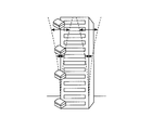
- FIG. 2 shows examples in which the sensor device 200 is installed in a building or a bridge.
- a sensor device having an acceleration sensor is provided for each floor of a building. With such a sensor device, the shaking of the building due to an earthquake can be observed for each floor.
- the sensor apparatus which has an acceleration sensor is provided in the various places of the bridge.
- sensor devices having a temperature sensor and sensor devices having a displacement sensor are provided at various locations on the bridge. As described above, these sensor devices 200 use the time information distributed from the distribution device 100 to execute the process of measuring the state at regular intervals and simultaneously (that is, synchronously).
- the distribution device 100 and the sensor device 200 are arranged in the same segment of the wired LAN and that no other device connection is connected on the network. Such a configuration provides time synchronization performance with a stable accuracy of 1 ms.
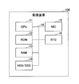
- FIG. 5 illustrates a hardware configuration example of the distribution apparatus 100 according to an embodiment of the present invention.
- the distribution apparatus 100 includes a CPU 11, ROM 12, RAM 13, HDD (Hard Disk Drive) / SSD (Solid State Drive) 14, NIC (Network Interface Card) 15, and RTC (Real Time Clock) 16.
- the CPU 11 executes a program that controls the operation of the distribution apparatus 100.
- the ROM 12 stores a system program executed by the CPU 11.
- the RAM 13 constitutes a work area for the CPU 11.
- the HDD / SSD 14 stores programs and data such as an OS and applications executed by the CPU 11.
- the NIC 15 includes a wired communication interface and its control device, and is used to communicate with the sensor device 200 and the server 300.
- the RTC 16 is a device for managing the local time.
- the bus 18 connects the above-described devices constituting the distribution device 100 to each other and exchanges data.
- the distribution apparatus 100 corrects the local time within a predetermined correction amount range with respect to the acquired reference time, and distributes the local time to the sensor device. Can do.
- the distribution apparatus 100 includes a wireless LAN module for performing communication with a wireless LAN together with or in place of the NIC 15, and a communication module for performing communication with Bluetooth (registered trademark) or ZigBee (registered trademark). May be. Although details will be described later, the distribution apparatus 100 may include a GPS receiver, an atomic clock, or a radio clock. The distribution apparatus 100 may include an input device such as a keyboard or a mouse that receives input from the user. Furthermore, the distribution apparatus 100 may include a display that presents information to the user. ⁇ 2.2 Sensor equipment ⁇ FIG. 6 illustrates a hardware configuration example of the sensor device 200 according to an embodiment of the present invention.
- the sensor device 200 in FIG. 6 is a configuration example of a sensor device having an acceleration sensor.
- the sensor device 200 includes a CPU 21, a ROM 22, a RAM 23, a NIC 24, an RTC 25, and an acceleration sensor 26.
- the CPU 21 executes a program for controlling the operation of the sensor device 200.
- the ROM 22 stores a program executed by the CPU 21.
- the RAM 23 constitutes a work area for the CPU 21.
- the NIC 24 includes a wired communication interface and its control device, and is used to communicate with the distribution device 100.
- the RTC 25 is a device for managing the local time.
- the acceleration sensor 26 is a device that detects acceleration applied to the sensor.
- the bus 27 connects the above-described devices constituting the sensor device 200 to each other and exchanges data.
- the sensor device 200 can correct the local time using the time information distributed from the distribution device 100 and execute predetermined processing at regular intervals.
- the sensor device 200 includes a wireless LAN module for performing communication with a wireless LAN together with or in place of the NIC 24 and a communication module for performing communication with Bluetooth (registered trademark) or ZigBee (registered trademark). May be. ⁇ 3. Functional configuration ⁇ Next, functional configurations of the distribution device 100 and the sensor device 200 according to an embodiment of the present invention will be described with reference to FIG. Note that FIG. 7 illustrates elements that are particularly relevant to the description of the present embodiment, among various elements included in the distribution device 100 and the sensor device 200.
- the distribution apparatus 100 includes a reference time acquisition unit 101, a local time management unit 102, a calculation unit 103, a correction unit 104, a time information distribution unit 105, a period information storage unit 151, and a correction amount information storage unit 152. And a threshold information storage unit 153.
- the period information storage unit 151, the correction amount information storage unit 152, and the threshold information storage unit 153 are realized by the HDD / SSD 14 of FIG.
- the cycle information storage unit 151 stores cycle information indicating a cycle T (unit: second) for distributing time information to the sensor device 200.
- the period T is determined in advance by the user by a parameter determination method described later.
- the correction amount information storage unit 152 stores correction amount information indicating a correction amount B that can correct the local time of the distribution apparatus 100 at a time.
- the correction amount B is determined in advance by the user by a parameter determination method described later.
- the correction amount B is determined according to the error tolerance range of the processing cycle of the sensor device 200.
- the threshold information storage unit 153 stores threshold information indicating a threshold S of a difference between the acquired reference time and the local time of the distribution apparatus 100.
- the threshold S is set to a value sufficiently larger than the correction amount B described above.
- the reference time acquisition unit 101 is realized mainly by the processing of the CPU 11 and the NIC 15, and acquires time information representing the reference time from the external server 300.
- the reference time acquisition unit 101 can acquire time information from the server 300 using, for example, an NTP client function.
- the reference time acquisition unit 101 can acquire time information from the server 300 using an arbitrary protocol.
- the reference time acquisition unit 101 may acquire the reference time by itself without acquiring the reference time from the server 300 via the NIC 15.
- the distribution device 100 may include a GPS receiver or a radio clock, and the reference time acquisition unit 101 may acquire the reference time through these devices.
- the reference time acquisition unit 101 can acquire the reference time at an arbitrary timing.
- the local time management unit 102 is realized mainly by the processing of the CPU 11 and the RTC 16, and manages the local time in the distribution apparatus 100.
- the local time may be held inside the distribution device or may be acquired from an external device.
- the calculation unit 103 is realized mainly by the processing of the CPU 11 and calculates a difference D between the reference time acquired by the reference time acquisition unit 101 and the local time acquired from the local time management unit 102.
- the correction unit 104 is realized mainly by the processing of the CPU 11, and determines how much the local time managed by the local time management unit 102 is corrected according to the magnitude of the difference D calculated by the calculation unit 103. At this time, the correction unit 104 refers to the correction amount information stored in the correction amount information storage unit 152 and the threshold information stored in the threshold information storage unit 153 to make a determination. And the correction
- Difference D ⁇ correction amount B adjust local time to reference time
- Correction amount B ⁇ difference D ⁇ threshold S make local time close to reference time within correction amount range
- threshold S ⁇ difference D Adjust local time to the reference time
- the local time management unit 102 manages immediately after the distribution apparatus 100 is started. The local time may be significantly different from the actual time, so the local time is adjusted to the reference time.
- the time information distribution unit 105 is realized mainly by the processing of the CPU 11 and the NIC 15.
- the time information distribution unit 105 refers to the period information stored by the period information storage unit 151 and distributes the time information including the local time managed by the local time management unit 102 to the sensor device 200 at a certain period T. To do.
- the time information distribution unit 105 distributes time information to the sensor device 200 using, for example, NTP.
- NTP When the NTP is used, the time information distribution unit 105 distributes the time information in response to the time distribution request transmitted from the sensor device 200.
- the distributed time information may be corrected as appropriate according to the propagation delay time of the network.
- a method for correcting the time information for example, a method described in Non-Patent Document 4 can be used.
- the time information distribution unit 105 can distribute time information to the sensor device 200 using an arbitrary protocol.
- time information distribution unit 105 holds the time when the time information was distributed immediately before, and sets the time obtained by adding the period T to the next time information distribution time.
- the distribution device 100 can distribute time information indicating the time corrected within a predetermined correction amount range to the sensor device 200. As a result, the sensor device 200 can continue to execute the measurement process within the range of the error tolerance of the process execution cycle.
- the sensor device 200 includes a time information reception unit 201, a local time management unit 202, a process execution unit 203, and a process result storage unit 251.
- the time information receiving unit 201 is realized mainly by the processing of the CPU 21 and the NIC 24, and receives the time information transmitted from the time information distributing unit 105 of the distribution device 100.
- the time information receiving unit 201 receives time information from the distribution apparatus 100 using, for example, NTP.
- the time information receiving unit 201 can receive time information from the distribution apparatus 100 using an arbitrary protocol.
- the local time management unit 202 is realized mainly by the processing of the CPU 21 and the RTC 25, and manages the local time of the sensor device 200.
- the local time management unit 202 adjusts the local time to the time indicated by the time information received by the time information receiving unit 201.
- the processing execution unit 203 is realized mainly by the processing of the CPU 21 and the acceleration sensor 26, and measures the acceleration applied to the acceleration sensor 26 at regular intervals. For example, in the case of measuring vibration derived from an earthquake applied to a structure, the process execution unit 203 executes acceleration measurement processing at intervals of about 5-10 milliseconds.
- the execution period of the processing is the purpose of measurement (detection of shaking due to earthquake, detection of abnormality of strength of buildings, etc.), structure to be measured (buildings, bridges, etc.), measurement data (vibration, strain, displacement, temperature) Etc.).
- the process execution unit 203 may execute not only the measurement process by the acceleration sensor process but also the measurement process by an arbitrary sensor at regular intervals. Moreover, the process execution part 203 may perform the general information processing which does not use a sensor at a fixed interval.
- the processing result storage unit 251 is realized by the ROM 22 of FIG. 6 and stores the processing result by the processing execution unit 203 together with the local time when the processing is executed.
- the sensor device 200 can execute the measurement process within a range that does not exceed the allowable error of the process execution cycle.
- the time information receiving unit 201 When receiving time information using NTP, the time information receiving unit 201 transmits a time distribution request to the distribution apparatus 100 according to a predetermined cycle, and receives time information as a response.
- the predetermined period is the same as the period indicated by the period information stored in the period information storage unit 151 of the distribution apparatus 100 in FIG. Therefore, as illustrated in FIG. 23, the sensor device 200 may include a cycle information storage unit 252 having the same function as the cycle information storage unit 151 of FIG. 7. That is, the time information receiving unit 201 can receive the time information from the distribution device 100 according to the cycle information stored in the cycle information storage unit 252. It is also possible to receive various information transmitted from the sensor device.
- the time information to be distributed may be corrected as appropriate according to the propagation delay time of the network.
- a method for correcting the time information for example, a method described in Non-Patent Document 4 can be used.
- ⁇ 4. Example of operation a processing flow of the distribution apparatus 100 and an operation example of the distribution system 1 according to an embodiment of the present invention will be described with reference to FIGS. Hereinafter, the processing of the distribution apparatus 100 will be described by dividing it into local time correction processing and time distribution processing.
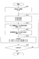
- FIG. 8 is a flowchart showing local time correction processing of distribution apparatus 100 according to an embodiment of the present invention.
- the reference time acquisition unit 101 acquires a reference time (step S101).
- the calculation unit 103 calculates a difference D between the reference time acquired in step S101 and the local time managed by the local time management unit 102 (step S102).
- the correction unit 104 determines how much the local time managed by the local time management unit 102 is to be corrected according to the magnitude of the difference D calculated in step S102.
- the distribution apparatus 100 is immediately after activation (that is, when the processing flow is executed for the first time after activation)
- the process proceeds to step S109 (Yes in step S103). Otherwise, the process proceeds to step S104 (No in step S103).
- the correction unit 104 compares the difference D calculated in step S102 with the threshold value S stored in the threshold value information storage unit 153 (step S104). If the difference D is greater than the threshold value S, the process proceeds to step S109 (Yes in step S105). Otherwise, the process proceeds to step S106 (No in step S105).
- the correction unit 104 compares the difference D calculated in step S102 with the correction amount B stored in the correction amount information storage unit 152 (step S106). If the difference D is greater than the correction amount B, the process proceeds to step S108 (Yes in step S107). Otherwise, the process proceeds to step S109 (No in step S107).
- step S108 the correction unit 104 corrects the local time within the correction amount range so that the local time approaches the reference time.
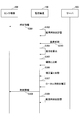
- FIG. 9 is a flowchart showing time distribution processing of the distribution apparatus 100 according to the embodiment of the present invention.
- the time information distribution unit 105 reads the local time managed by the local time management unit 102 (step S201).
- the time information distribution unit 105 reads the cycle information stored in the cycle information storage unit 151 (step S202).
- the time information distribution unit 105 determines whether the time obtained by adding the time when the time information was immediately distributed and the period T read in step S202 is equal to the local time read in step S201 (or the local time has passed). Judgment) As a result, if they are equal (or the local time has elapsed) (Yes in step S203), the process proceeds to step S204, and the time information distribution unit 105 distributes the time information indicating the local time to the sensor device 200. . On the other hand, if they are not equal (or if the local time has not elapsed), the process returns to step S201 (No in step S203).
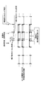
- FIG. 10 is a sequence diagram illustrating an operation example of the distribution system 1 according to the embodiment of the present invention. Here, typically only one sensor device 200 is shown.
- the time information distribution unit 105 of the distribution device 100 acquires the local time managed by the local time management unit 102, and transmits this local time to the time information reception unit 201 of the sensor device 200 as time information (step). S301).
- the time information distribution unit 105 of the distribution device 100 internally stores the time when the time information was distributed in step S301.
- the reference time acquisition unit 101 of the distribution apparatus 100 acquires the reference time from the server 300.
- the calculation unit 103 of the distribution apparatus 100 calculates a difference D between the reference time acquired in step S303 and the local time managed by the local time management unit 102 (step S304).
- the correction unit 104 of the distribution apparatus 100 compares the difference D calculated in step S304 with the threshold value S stored in the threshold value information storage unit 153 (step S305).
- the difference D is equal to or less than the threshold value S, and the process proceeds to the next process.
- the correction unit 104 of the distribution apparatus 100 compares the difference D calculated in step S304 with the correction amount B stored in the correction amount information storage unit 152 (step S306).
- the difference D is larger than the correction amount D, the process proceeds to the next process.
- the correcting unit 104 of the distribution apparatus 100 corrects the local time within the correction amount range so that the local time approaches the reference time acquired in step S303 (step S307).
- the time information distribution unit 105 of the distribution apparatus 100 detects that the local time corrected in step S307 has passed a time obtained by adding a period to the time stored in step S302.
- the time information is transmitted to the sensor device 200 (step S308).
- the time information distribution unit 105 of the distribution apparatus 100 internally stores the time at which the time information was distributed in step S308 (step S309).
- the distribution apparatus 100 can gradually correct the local time with respect to the reference time, and distribute the local time to the sensor device. .
- the sensor device that has received the local time can execute a predetermined process at a stable cycle.
- the correction unit 104 of the distribution apparatus 100 may further correct the local time without acquiring the reference time again after step S309.
- the difference D2 between the corrected local time of the distribution apparatus 100 and the reference time is an amount obtained by subtracting the correction amount of the local time in step S307 from the difference D calculated in step S304. Therefore, the correction
- ⁇ 5 Effect ⁇ Next, the effects obtained by the distribution apparatus 100 according to the embodiment of the present invention will be described with reference to FIGS. 11 to 15 and FIG.
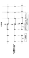
- FIG. 11 shows how the distribution device 100 according to an embodiment of the present invention distributes time information to three sensor devices.
- the difference D between the reference time and the local time of the distribution apparatus 100 is within the range of the correction amount B (when (1) difference D ⁇ correction amount B described above).
- the reference time is advanced by a certain time with respect to the local time of the distribution apparatus 100 (difference D), but the difference is equal to or less than the correction amount B. Therefore, the local time is corrected to coincide with the reference time. Thereafter, the distribution apparatus 100 distributes the time information according to the corrected local time. Therefore, after each sensor device receives the time information, the processing cycle is temporarily shortened by the difference D.
- FIG. 12 schematically shows the distribution of time information by a conventional distribution device not according to the present invention.
- the difference D between the reference time and the local time of the distribution apparatus is not within the range of the correction amount B ((2) correction amount B ⁇ difference D ⁇ threshold value S).
- the distribution device not according to the present invention adjusts the local time to the reference time regardless of the difference between the reference time and the local time. Therefore, as a result of distributing the time information according to the corrected local time, the distribution apparatus 100 does not satisfy the request for the execution period of the processing by each sensor device.
- an example has been shown in which the reference time is ahead of the local time of the distribution apparatus 100, but the same applies when the reference time is behind the local time of the distribution apparatus 100.
- FIG. 13 schematically shows distribution of time information by the distribution apparatus 100 according to an embodiment of the present invention.
- the difference D between the reference time and the local time of the distribution apparatus is not within the range of the correction amount B ((2) correction amount B ⁇ difference D ⁇ threshold value S).
- the distribution apparatus 100 according to the embodiment of the present invention adjusts the local time to the reference time with the correction amount B as a limit. Therefore, for example, even if the accuracy of the reference time itself is insufficient or a communication delay between the server 300 that provides the reference time and the distribution device 100 occurs, the time information is sent to the sensor device while maintaining a certain period. Can be delivered. As a result, the sensor device can execute the measurement process at a stable cycle.
- FIG. 14 shows an example in which the reference time and the local time are synchronized by the distribution apparatus 100 according to the embodiment of the present invention further correcting the local time after the correction process shown in FIG. .
- the distribution apparatus 100 corrects the local time by the correction amount B so as to approach the acquired reference time. Thereafter, the distribution apparatus 100 corrects the local time again within the range of the correction amount B before acquiring the reference time again.
- the distribution apparatus 100 repeats the same processing until the local time matches the reference time. In this way, the distribution apparatus 100 can gradually adjust the local time within the range of the correction amount B to the reference time. As a result, the change in the time information distribution cycle falls within a certain range, and the sensor device can execute the measurement process at a stable cycle.
- FIG. 15 shows a conventional example in which the sensor device 200 acquires the reference time directly from the external server 300 or the like. As can be seen from the figure, the sensor device acquires the reference time from the external server 300 through each route. As a result, an error occurs in the time synchronization period and the time itself.
- FIG. 22 illustrates a state of time distribution when the distribution apparatus 100 and the sensor device perform time synchronization by NTP.
- the distribution apparatus 100 receives a time synchronization request from each sensor device after acquiring the reference time, and distributes time information to each sensor device.
- the distribution apparatus 100 or the sensor device corrects and uses time information in consideration of the propagation delay time of the network and the like. Thereby, a sensor apparatus can perform a measurement process with the stable period using NTP already prevailing.
- FIG. 16 shows a configuration example of a distribution system 1A different from the distribution system 1 shown in FIG.
- the distribution apparatus 100 acquires the reference time independently.
- the distribution apparatus 100 includes a GPS receiver or a radio clock. By setting it as such a structure, the structure of a delivery system can be simplified.
- FIG. 17 shows a configuration example of a distribution system 1B different from the distribution systems shown in FIGS.
- the distribution apparatus 100 can acquire the reference time independently.
- the distribution device 100 and the sensor device 200 of the distribution system 1B are connected by a signal line for transmitting a synchronous clock and a signal line for transmitting digital time information corresponding to the synchronous clock.
- time when time is distributed as a digital value, it is easily affected by variations in communication delay time.
- using a synchronous clock allows time to be distributed without receiving such a delay. ⁇ 7.
- the period T and the correction amount B are determined according to the following method before the distribution apparatus 100 and the sensor device 200 are installed, and are stored in the period information storage unit and the correction information storage unit as the period information and the correction amount information, respectively. Is done.
- the period T and the correction amount B are determined based on the tolerance of the sensor device to the time (or the tolerance of the processing execution cycle) and the accuracy of the local clock of the sensor device. How to do it.
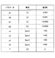
- the correction amount B includes a correction amount B1 (negative value, unit: second) for correcting the local time to be delayed, and a correction amount B2 (positive value, for correcting the local time to advance). (Unit: second) (
- step S301 when the measurement target of the sensor device 200 (for example, the degree of vibration of the structure due to the earthquake) is determined by the user, the allowable error with respect to the time of the sensor device (or the allowable error of the processing execution cycle). ) Is determined.
- the allowable error to the time of the sensor device is represented by A1 (unit: second) and A2 (unit: second).
- A1 is a negative value
- A2 (however, generally, if the minimum value of the allowable error is A1 and the maximum value is A2, the following equation holds).
- step S302 the correction amounts B1 and B2 are selected so as to be within the tolerances A1 and A2 of the time of the sensor device.
- the relationship among A1, A2, B1, and B2 is expressed by the following equation.
- the selected value is preferably selected.
- step S303 the accuracy of the local clock of the sensor device 200 is selected.
- the accuracy of the local timepiece of the sensor device 200 is determined by the performance of the RTC 25 mounted on the sensor device 200.
- the accuracy of the local clock is represented by x1 (negative value, unit: ppm, Parts per Million) and x2 (positive value, unit: ppm).
- x1 negative value
- x2 positive value
- both x1 and x2 may be a positive value or a negative value.
- step S304 a cycle T in which the distribution apparatus 100 distributes time information is determined.
- the period T needs to be selected so that the error of the local clock of the sensor device 200 accumulated during the period T does not exceed the allowable error with respect to the time of the sensor device 200. Therefore, the period T is selected so as to satisfy the following expression.
- step S305 when T selected in step S304 is an appropriate value in the configuration of the distribution system 1, this value is stored in the cycle information storage unit 151 as cycle information.
- T selected in step S304 is not an appropriate value (on the distribution system, if the time is distributed at period T, the processing load or the network load is too large), the process returns to step S303, and the accuracy of the local clock and the period T Is selected again.
- the distribution apparatus 100 performs stable time distribution within the allowable error range with respect to the time of the sensor device 200 or the execution period by using the period T and the correction amount B (B1, B2) obtained by the above method. be able to.
- FIG. 19 shows an example of each parameter selected by the above method.
- step S401 similar to step S301 of FIG. 18, tolerances to the time of the sensor device (or tolerances of processing execution cycles) A1 and A2 are determined.
- step S402 correction amounts B1 and B2 are selected as in step S302 of FIG.
- step S403 as in step S303 in FIG. 18, the precision x1 and x2 of the local clock of the sensor device 200 is selected.
- step S404 the accuracy of the local clock of the distribution apparatus 100 is selected.
- the accuracy of the local clock of the distribution apparatus 100 is determined by the performance of the RTC 16 mounted on the distribution apparatus 100.
- the accuracy of the local clock is represented by y1 (negative value, unit: ppm) and y2 (positive value, unit: ppm).
- y1 is a negative value
- y2 is a positive value
- both y1 and y2 may be a positive value or a negative value.
- step S405 a cycle T in which the distribution device 100 distributes time information is determined.
- the period T is selected so that the sum of the error of the local clock of the distribution apparatus 100 and the error of the local clock of the sensor device 200 does not exceed the allowable error with respect to the time of the sensor device 200 during the period T. Need to be done. Therefore, the period T is selected so as to satisfy the following expression.
- step S406 when T selected in step S405 is an appropriate value in the configuration of the distribution system 1, this value is stored in the cycle information storage unit 151 as cycle information. On the other hand, if T selected in step S405 is not an appropriate value, the process returns to step S402, and the correction amounts B1, B2, the accuracy x1, x2, y1, y2 of the local clock of the sensor device and the distribution device, and the period T Is selected again.
- the distribution apparatus 100 uses the period T and the correction amount B (B1, B2) obtained by the above method, and thereby distributes the time more stably within the allowable error range with respect to the time of the sensor device 200 or the execution period. It can be performed.
- FIG. 20 shows an example of each parameter selected by the above method.
- Distribution device 101 Reference time acquisition unit 102 Local time management unit 103 Calculation unit 104 Correction unit 105 Time information distribution unit 151 Period information storage unit 152 Correction amount information storage unit 153 Threshold information storage unit 200 Sensor device 201 Time information reception unit 202 Local time management unit 203 Processing execution unit 251 Processing result storage unit 300 Server
Priority Applications (4)
| Application Number | Priority Date | Filing Date | Title |
|---|---|---|---|
| CN201480008206.7A CN104981742B (zh) | 2013-06-12 | 2014-04-22 | 分发装置、分发系统以及分发方法 |
| EP14810585.1A EP3009897B1 (de) | 2013-06-12 | 2014-04-22 | Verteilungsvorrichtung, verteilungssystem und verteilungsverfahren |
| JP2015522628A JP6079879B2 (ja) | 2013-06-12 | 2014-04-22 | 配信装置、配信システム及び配信方法 |
| US14/822,724 US9519306B2 (en) | 2013-06-12 | 2015-08-10 | Distribution device, distribution system, and distribution method |
Applications Claiming Priority (2)
| Application Number | Priority Date | Filing Date | Title |
|---|---|---|---|
| JP2013123863 | 2013-06-12 | ||
| JP2013-123863 | 2013-06-12 |
Related Child Applications (1)
| Application Number | Title | Priority Date | Filing Date |
|---|---|---|---|
| US14/822,724 Continuation US9519306B2 (en) | 2013-06-12 | 2015-08-10 | Distribution device, distribution system, and distribution method |
Publications (1)
| Publication Number | Publication Date |
|---|---|
| WO2014199729A1 true WO2014199729A1 (ja) | 2014-12-18 |
Family
ID=52022031
Family Applications (1)
| Application Number | Title | Priority Date | Filing Date |
|---|---|---|---|
| PCT/JP2014/061328 WO2014199729A1 (ja) | 2013-06-12 | 2014-04-22 | 配信装置、配信システム及び配信方法 |
Country Status (5)
| Country | Link |
|---|---|
| US (1) | US9519306B2 (de) |
| EP (1) | EP3009897B1 (de) |
| JP (1) | JP6079879B2 (de) |
| CN (1) | CN104981742B (de) |
| WO (1) | WO2014199729A1 (de) |
Cited By (6)
| Publication number | Priority date | Publication date | Assignee | Title |
|---|---|---|---|---|
| JP2018021825A (ja) * | 2016-08-03 | 2018-02-08 | パナソニックIpマネジメント株式会社 | 通信システム、端末、通信システムの時刻補正方法、及びプログラム |
| JP2019129498A (ja) * | 2018-01-26 | 2019-08-01 | セイコーソリューションズ株式会社 | 時刻配信装置、および時刻調整方法 |
| JP2019158734A (ja) * | 2018-03-15 | 2019-09-19 | セイコークロック株式会社 | 計時装置、計時システム、及び計時方法 |
| JP2022131336A (ja) * | 2021-02-26 | 2022-09-07 | 株式会社安川電機 | コントローラ、機器制御システム、時刻同期方法、および時刻同期プログラム |
| US11770235B2 (en) | 2021-02-26 | 2023-09-26 | Kabushiki Kaisha Yaskawa Denki | Time synchronization of controller |
| WO2024018787A1 (ja) * | 2022-07-20 | 2024-01-25 | 株式会社オートネットワーク技術研究所 | 車載装置、時刻同期方法および時刻同期プログラム |
Families Citing this family (13)
| Publication number | Priority date | Publication date | Assignee | Title |
|---|---|---|---|---|
| US9471092B2 (en) * | 2012-02-03 | 2016-10-18 | MCube Inc. | Distributed MEMS devices time synchronization methods and system |
| US10169047B2 (en) * | 2014-06-24 | 2019-01-01 | Intel Corporation | Computing devices, methods, and storage media for a sensor layer and sensor usages in an operating system-absent environment |
| CN105429724B (zh) * | 2015-10-20 | 2018-03-23 | 北京小鸟听听科技有限公司 | 时钟校正方法、时钟校正装置及音箱 |
| CN106325059A (zh) * | 2016-10-26 | 2017-01-11 | 中国计量大学 | 一种数字时钟的蓝牙校准方法 |
| CN108631897B (zh) * | 2017-03-17 | 2019-10-22 | 杭州海康威视数字技术股份有限公司 | 一种网络校时方法及装置 |
| CN107195308B (zh) * | 2017-04-14 | 2021-03-16 | 苏州科达科技股份有限公司 | 音视频会议系统的混音方法、装置及系统 |
| US11019585B1 (en) | 2018-07-24 | 2021-05-25 | Sprint Communications Company L.P. | Network generated precision time |
| JP2020072334A (ja) * | 2018-10-30 | 2020-05-07 | セイコーエプソン株式会社 | センサーデータ処理システム及びセンサーデータ同期システム |
| JP2020119225A (ja) * | 2019-01-23 | 2020-08-06 | セイコーエプソン株式会社 | 管理方法、構造物監視装置および構造物監視システム |
| CN110620632B (zh) | 2019-09-12 | 2021-02-23 | 华为技术有限公司 | 一种时间同步方法及装置 |
| JP7318557B2 (ja) * | 2020-02-18 | 2023-08-01 | トヨタ自動車株式会社 | コミュニケーションシステム、制御方法及び制御プログラム |
| CN111399367A (zh) * | 2020-03-20 | 2020-07-10 | 深圳市帅鸽美羽科技有限公司 | 基于鸽钟设备的时间校正方法、服务器及存储介质 |
| US11940835B2 (en) * | 2022-02-25 | 2024-03-26 | FMAD Engineering (SNG) Pte. Ltd. | Clock disciplining and synchronizing |
Citations (11)
| Publication number | Priority date | Publication date | Assignee | Title |
|---|---|---|---|---|
| JPH11212926A (ja) * | 1998-01-27 | 1999-08-06 | Nec Commun Syst Ltd | Unixシステムにおけるシステム時刻補正方法 |
| JP2002031693A (ja) * | 2000-07-17 | 2002-01-31 | Mitsubishi Electric Corp | エレベーターの時刻修正装置及びその修正方法 |
| JP2003110562A (ja) | 2001-09-27 | 2003-04-11 | Nec Eng Ltd | 時刻同期システム及び時刻同期方法 |
| JP2006349364A (ja) * | 2005-06-13 | 2006-12-28 | Toyota Infotechnology Center Co Ltd | 時刻補正方法 |
| JP2007018211A (ja) | 2005-07-07 | 2007-01-25 | Yamatake Corp | 自律型データロガー |
| JP2007263753A (ja) * | 2006-03-28 | 2007-10-11 | Fujitsu Ltd | テレメーターシステムの子局装置 |
| JP2010278546A (ja) | 2009-05-26 | 2010-12-09 | Hitachi Ltd | 時刻同期網及び通信装置 |
| JP2011214937A (ja) * | 2010-03-31 | 2011-10-27 | Sogo Keibi Hosho Co Ltd | プログラム、機器 |
| JP2012202897A (ja) | 2011-03-28 | 2012-10-22 | Nomura Research Institute Ltd | クライアント端末、サーバ端末、時刻同期方法、プログラム |
| JP2012211881A (ja) * | 2011-03-31 | 2012-11-01 | Yokogawa Electric Corp | ネットワーク機器、および同機器における時刻同期方法 |
| JP2013096974A (ja) * | 2011-11-07 | 2013-05-20 | Japan Radio Co Ltd | 時刻制御装置及び時刻制御方法 |
Family Cites Families (10)
| Publication number | Priority date | Publication date | Assignee | Title |
|---|---|---|---|---|
| US7352715B2 (en) * | 2001-11-30 | 2008-04-01 | Cellnet Innovations, Inc. | Time synchronization using dynamic thresholds |
| US9565275B2 (en) * | 2012-02-09 | 2017-02-07 | Rockwell Automation Technologies, Inc. | Transformation of industrial data into useful cloud information |
| CN100535824C (zh) * | 2004-09-23 | 2009-09-02 | 华为技术有限公司 | 提高卫星时间同步脉冲保持性能的方法 |
| WO2006127994A2 (en) * | 2005-05-25 | 2006-11-30 | Radioframe Networks, Inc. | Pll with phase clipping and resynchronization |
| US7710944B1 (en) * | 2006-09-15 | 2010-05-04 | Itt Manufacturing Enterprises, Inc. | Method and apparatus for time-of-day synchronization between network nodes |
| US8073976B2 (en) * | 2008-03-27 | 2011-12-06 | Microsoft Corporation | Synchronizing clocks in an asynchronous distributed system |
| EP2467796B1 (de) * | 2009-08-17 | 2020-04-08 | Koninklijke Philips N.V. | System und verfahren zur synchronisierung einer patientenüberwachungsvorrichtung mit einem zentralen server |
| JP5649505B2 (ja) * | 2011-04-19 | 2015-01-07 | 株式会社東芝 | 同期制御システム |
| CN102355319B (zh) * | 2011-08-17 | 2015-07-08 | 中国科学院深圳先进技术研究院 | 无线传感器网络中的时间同步方法及系统 |
| US8959381B2 (en) * | 2012-09-05 | 2015-02-17 | Khalifa University of Science, Technology, and Research | Method and system for clock offset and skew estimation |
-
2014
- 2014-04-22 CN CN201480008206.7A patent/CN104981742B/zh active Active
- 2014-04-22 WO PCT/JP2014/061328 patent/WO2014199729A1/ja active Application Filing
- 2014-04-22 EP EP14810585.1A patent/EP3009897B1/de active Active
- 2014-04-22 JP JP2015522628A patent/JP6079879B2/ja active Active
-
2015
- 2015-08-10 US US14/822,724 patent/US9519306B2/en active Active
Patent Citations (11)
| Publication number | Priority date | Publication date | Assignee | Title |
|---|---|---|---|---|
| JPH11212926A (ja) * | 1998-01-27 | 1999-08-06 | Nec Commun Syst Ltd | Unixシステムにおけるシステム時刻補正方法 |
| JP2002031693A (ja) * | 2000-07-17 | 2002-01-31 | Mitsubishi Electric Corp | エレベーターの時刻修正装置及びその修正方法 |
| JP2003110562A (ja) | 2001-09-27 | 2003-04-11 | Nec Eng Ltd | 時刻同期システム及び時刻同期方法 |
| JP2006349364A (ja) * | 2005-06-13 | 2006-12-28 | Toyota Infotechnology Center Co Ltd | 時刻補正方法 |
| JP2007018211A (ja) | 2005-07-07 | 2007-01-25 | Yamatake Corp | 自律型データロガー |
| JP2007263753A (ja) * | 2006-03-28 | 2007-10-11 | Fujitsu Ltd | テレメーターシステムの子局装置 |
| JP2010278546A (ja) | 2009-05-26 | 2010-12-09 | Hitachi Ltd | 時刻同期網及び通信装置 |
| JP2011214937A (ja) * | 2010-03-31 | 2011-10-27 | Sogo Keibi Hosho Co Ltd | プログラム、機器 |
| JP2012202897A (ja) | 2011-03-28 | 2012-10-22 | Nomura Research Institute Ltd | クライアント端末、サーバ端末、時刻同期方法、プログラム |
| JP2012211881A (ja) * | 2011-03-31 | 2012-11-01 | Yokogawa Electric Corp | ネットワーク機器、および同機器における時刻同期方法 |
| JP2013096974A (ja) * | 2011-11-07 | 2013-05-20 | Japan Radio Co Ltd | 時刻制御装置及び時刻制御方法 |
Non-Patent Citations (5)
| Title |
|---|
| "The Institute of Electronics, Information and Communication Engineers (Knowledge Base", 2010, INSTITUTE OF ELECTRONICS, INFORMATION AND COMMUNICATION ENGINEERS |
| MAKOTO SUZULD ET AL.: "Research Trends in Wireless Sensor Network Time Synchronization Technology", TECHNICAL RESEARCH REPORT NO. 2008001, 24 April 2008 (2008-04-24) |
| SATORU SALCAUE ET AL.: "Applied MEMS Micro-vibration Sensors and Structural Health Monitoring", FUJI ELECTRIC JOURNAL, vol. 84, no. 4, 2011, pages 269 - 273 |
| See also references of EP3009897A4 |
| SHOJI YOSHIDA ET AL.: "Development of Real-time Ethernet (registered trademark) Optical Transmission to Provide with Sampling Synchronization by IEEE1588", 31 August 2010, THE INSTITUTE OF ELECTRICAL ENGINEERS OF JAPAN |
Cited By (7)
| Publication number | Priority date | Publication date | Assignee | Title |
|---|---|---|---|---|
| JP2018021825A (ja) * | 2016-08-03 | 2018-02-08 | パナソニックIpマネジメント株式会社 | 通信システム、端末、通信システムの時刻補正方法、及びプログラム |
| JP2019129498A (ja) * | 2018-01-26 | 2019-08-01 | セイコーソリューションズ株式会社 | 時刻配信装置、および時刻調整方法 |
| JP2019158734A (ja) * | 2018-03-15 | 2019-09-19 | セイコークロック株式会社 | 計時装置、計時システム、及び計時方法 |
| JP2022131336A (ja) * | 2021-02-26 | 2022-09-07 | 株式会社安川電機 | コントローラ、機器制御システム、時刻同期方法、および時刻同期プログラム |
| US11770235B2 (en) | 2021-02-26 | 2023-09-26 | Kabushiki Kaisha Yaskawa Denki | Time synchronization of controller |
| JP7382980B2 (ja) | 2021-02-26 | 2023-11-17 | 株式会社安川電機 | コントローラ、機器制御システム、時刻同期方法、および時刻同期プログラム |
| WO2024018787A1 (ja) * | 2022-07-20 | 2024-01-25 | 株式会社オートネットワーク技術研究所 | 車載装置、時刻同期方法および時刻同期プログラム |
Also Published As
| Publication number | Publication date |
|---|---|
| US9519306B2 (en) | 2016-12-13 |
| EP3009897A1 (de) | 2016-04-20 |
| CN104981742B (zh) | 2017-09-19 |
| CN104981742A (zh) | 2015-10-14 |
| JP6079879B2 (ja) | 2017-02-15 |
| US20150346760A1 (en) | 2015-12-03 |
| EP3009897A4 (de) | 2017-02-01 |
| EP3009897B1 (de) | 2024-01-03 |
| JPWO2014199729A1 (ja) | 2017-02-23 |
Similar Documents
| Publication | Publication Date | Title |
|---|---|---|
| JP6079879B2 (ja) | 配信装置、配信システム及び配信方法 | |
| EP3564921B1 (de) | Erfassungssystem und zeitsynchronisationsverfahren | |
| Li et al. | Efficient time synchronization for structural health monitoring using wireless smart sensor networks | |
| KR101484871B1 (ko) | 마스터 장치와 슬레이브 장치 및 시각 동기 방법 | |
| KR20090032306A (ko) | 네트워크상의 타임 동기화 시스템 및 방법 | |
| US20110222561A1 (en) | Systems and methods for providing time synchronization | |
| Kim et al. | Synchronized sensing for wireless monitoring of large structures | |
| Volgyesi et al. | Time synchronization services for low-cost fog computing applications | |
| US11683772B2 (en) | Continuous synchronization of multiple radio devices to physical time | |
| WO2016177090A1 (zh) | 时钟同步方法及装置 | |
| US20160170382A1 (en) | Time Synchronization Control Apparatus And Method | |
| JP5372315B2 (ja) | テレメーターシステムの子局装置 | |
| DK2667021T3 (en) | Timestamp in wind turbines | |
| JP7073920B2 (ja) | 時刻付与方法、時刻付与装置及びプログラム | |
| JP2007163330A (ja) | 時刻情報通信システム | |
| KR102064575B1 (ko) | 디바이스 간의 시각 동기 정밀도를 향상시키는 방법, 장치, 시스템 및 컴퓨터 프로그램 | |
| WO2015033532A1 (ja) | 時刻同期システム | |
| KR102093223B1 (ko) | 전력 제어 시스템의 시간 동기화 장치 및 그 방법 | |
| WO2022244156A1 (ja) | 測定器、測定方法および時刻同期システム | |
| EP2398173A1 (de) | Ferngesteuertes E/A-System und Synchronisationsverfahren dafür | |
| EP3343809A1 (de) | Relaisvorrichtung, kommunikationssystem und fehlerdetektionsverfahren | |
| EP4152763B1 (de) | System zum sammeln von informationen und verfahren zum sammeln von informationen | |
| Shim et al. | Provisioning High-Precision Clock Synchronization between Uavs for Low Latency Networks | |
| TW202403336A (zh) | 時脈同步 | |
| JP2015014536A (ja) | クライアント装置 |
Legal Events
| Date | Code | Title | Description |
|---|---|---|---|
| 121 | Ep: the epo has been informed by wipo that ep was designated in this application |
Ref document number: 14810585 Country of ref document: EP Kind code of ref document: A1 |
|
| ENP | Entry into the national phase |
Ref document number: 2015522628 Country of ref document: JP Kind code of ref document: A |
|
| WWE | Wipo information: entry into national phase |
Ref document number: 2014810585 Country of ref document: EP |
|
| NENP | Non-entry into the national phase |
Ref country code: DE |