WO2014199729A1 - Distribution device, distribution system, and distribution method - Google Patents
Distribution device, distribution system, and distribution method Download PDFInfo
- Publication number
- WO2014199729A1 WO2014199729A1 PCT/JP2014/061328 JP2014061328W WO2014199729A1 WO 2014199729 A1 WO2014199729 A1 WO 2014199729A1 JP 2014061328 W JP2014061328 W JP 2014061328W WO 2014199729 A1 WO2014199729 A1 WO 2014199729A1
- Authority
- WO
- WIPO (PCT)
- Prior art keywords
- time
- distribution
- local
- unit
- sensor device
- Prior art date
Links
Images


Classifications
-
- H—ELECTRICITY
- H04—ELECTRIC COMMUNICATION TECHNIQUE
- H04J—MULTIPLEX COMMUNICATION
- H04J3/00—Time-division multiplex systems
- H04J3/02—Details
- H04J3/06—Synchronising arrangements
- H04J3/0635—Clock or time synchronisation in a network
- H04J3/0638—Clock or time synchronisation among nodes; Internode synchronisation
- H04J3/0658—Clock or time synchronisation among packet nodes
- H04J3/0661—Clock or time synchronisation among packet nodes using timestamps
-
- G—PHYSICS
- G06—COMPUTING; CALCULATING OR COUNTING
- G06F—ELECTRIC DIGITAL DATA PROCESSING
- G06F1/00—Details not covered by groups G06F3/00 - G06F13/00 and G06F21/00
- G06F1/04—Generating or distributing clock signals or signals derived directly therefrom
- G06F1/08—Clock generators with changeable or programmable clock frequency
-
- G—PHYSICS
- G06—COMPUTING; CALCULATING OR COUNTING
- G06F—ELECTRIC DIGITAL DATA PROCESSING
- G06F1/00—Details not covered by groups G06F3/00 - G06F13/00 and G06F21/00
- G06F1/04—Generating or distributing clock signals or signals derived directly therefrom
- G06F1/10—Distribution of clock signals, e.g. skew
-
- G—PHYSICS
- G06—COMPUTING; CALCULATING OR COUNTING
- G06F—ELECTRIC DIGITAL DATA PROCESSING
- G06F1/00—Details not covered by groups G06F3/00 - G06F13/00 and G06F21/00
- G06F1/04—Generating or distributing clock signals or signals derived directly therefrom
- G06F1/12—Synchronisation of different clock signals provided by a plurality of clock generators
-
- G—PHYSICS
- G06—COMPUTING; CALCULATING OR COUNTING
- G06F—ELECTRIC DIGITAL DATA PROCESSING
- G06F1/00—Details not covered by groups G06F3/00 - G06F13/00 and G06F21/00
- G06F1/04—Generating or distributing clock signals or signals derived directly therefrom
- G06F1/14—Time supervision arrangements, e.g. real time clock
-
- H—ELECTRICITY
- H04—ELECTRIC COMMUNICATION TECHNIQUE
- H04Q—SELECTING
- H04Q9/00—Arrangements in telecontrol or telemetry systems for selectively calling a substation from a main station, in which substation desired apparatus is selected for applying a control signal thereto or for obtaining measured values therefrom
- H04Q9/04—Arrangements for synchronous operation
-
- G—PHYSICS
- G04—HOROLOGY
- G04G—ELECTRONIC TIME-PIECES
- G04G5/00—Setting, i.e. correcting or changing, the time-indication
-
- H—ELECTRICITY
- H04—ELECTRIC COMMUNICATION TECHNIQUE
- H04J—MULTIPLEX COMMUNICATION
- H04J3/00—Time-division multiplex systems
- H04J3/02—Details
- H04J3/06—Synchronising arrangements
- H04J3/0635—Clock or time synchronisation in a network
- H04J3/0638—Clock or time synchronisation among nodes; Internode synchronisation
- H04J3/0658—Clock or time synchronisation among packet nodes
- H04J3/0661—Clock or time synchronisation among packet nodes using timestamps
- H04J3/0667—Bidirectional timestamps, e.g. NTP or PTP for compensation of clock drift and for compensation of propagation delays
Definitions
- the present invention relates to a distribution device, a distribution system, and a distribution method.
- a monitoring technique in which a sensor device including a sensor represented by an acceleration sensor or a displacement sensor is attached to a structure such as a building or a bridge, and the state of the structure is monitored (Non-patent Document 1).
- a sensor device used in the monitoring technique executes a process of detecting a change in the state (acceleration, position, etc.) of the structure at a constant cycle.
- the result of the processing is temporarily recorded in the sensor device or the like together with time information.
- the recorded result is transmitted to an external device via a network or the like, for example.
- Sensor device executes processing for detecting a change in state at a constant cycle.
- the period can be a very short period depending on the purpose or object of monitoring. For example, in order to analyze vibrations caused by microtremors or earthquakes, it is necessary for the acceleration sensor to continue measuring acceleration at a constant cycle of about 5-10 milliseconds.
- the sensor device synchronizes the time using time information provided from the outside in order to detect and record vibrations applied to the structure.
- These sensor devices are connected to an external device for managing the time through a network, and synchronize the time using a protocol such as NTP (Network Time Protocol) or RBS (Reference Broadcast Synchronization) (Non-Patent Documents 2 and 3).
- NTP Network Time Protocol
- RBS Reference Broadcast Synchronization
- Patent Document 1 discloses a technology in which a plurality of devices having a reception function of a radio clock acquire the reference time by using a standard radio wave to synchronize the time of all devices.
- Patent Document 2 uses a difference time between a time derived from GPS and a time derived from a stable and highly accurate original oscillation clock to determine a correction amount of time, and through Synchronous Ethernet (registered trademark), A technique for performing time synchronization of base stations and communication devices connected to each other is disclosed.
- Patent Document 3 discloses a time synchronization system that performs time synchronization using NTP when the number of time synchronization requests transmitted from a client to a server reaches a certain number.
- Patent Document 4 discloses a technique in which an NTP server that has received a time synchronization request from an NTP client transmits determination information to the NTP client, and the client determines whether to perform time synchronization using the determination information. ing.
- a device used for monitoring corrects the time of its own local clock using time information provided from an external device. And an apparatus records the result of the process performed with the fixed period using local time.
- the device performs correction of the local time.
- the result of processing by the device is not recorded at a fixed period, and there is a possibility that inconvenience may occur when the result is analyzed later.
- the present invention has been made in view of such a problem, and an object thereof is to distribute time information so that a device can execute processing at a stable cycle.
- a distribution apparatus that distributes time information to one or more devices, A storage unit that stores correction amount information indicating a correction amount for correcting the local time of the distribution device at a time; An acquisition unit for acquiring a reference time; A calculation unit for obtaining a difference between the acquired reference time and the local time; A correction unit that corrects the local time by the correction amount when the obtained difference is larger than the correction amount; A delivery unit that delivers time information indicating the corrected local time to the device; Have
- the distribution system in one embodiment of the present invention is: A distribution system including one or more devices and a distribution device that distributes time information to the devices,
- the distribution device includes: A storage unit that stores correction amount information indicating a correction amount for correcting the local time of the distribution device at a time; An acquisition unit for acquiring a reference time; A calculation unit for obtaining a difference between the acquired reference time and the local time; A first correction unit that corrects the local time by the correction amount when the obtained difference is larger than the correction amount; A delivery unit that delivers time information indicating the corrected local time to the device;
- the equipment is A receiving unit that receives the time information distributed by the distributing unit; A management unit that corrects the local time of the device so as to match the time indicated by the received time information; Have
- the distribution method in one embodiment of the present invention is: A distribution method for distributing time information to one or more devices, An acquisition stage for acquiring a reference time; A calculation step for obtaining a difference between the acquired reference time and the local time of the distribution device; A correction step for correcting the local time by the correction amount when the obtained difference is larger than a correction amount for correcting the local time at a time; A distribution stage of distributing time information indicating the corrected local time to the device; Have
- the time information can be distributed so that the device can execute the process at a stable cycle.
- the figure showing the example of composition of the distribution system in one embodiment of the present invention The figure showing the example of installation of the sensor apparatus in one Embodiment of this invention.
- the figure showing the example of installation of the sensor apparatus in one Embodiment of this invention The figure showing the example of installation of the sensor apparatus in one Embodiment of this invention.
- the figure showing the example of installation of the sensor apparatus in one Embodiment of this invention The hardware block diagram of the delivery apparatus in one Embodiment of this invention.
- the functional block diagram of the delivery apparatus and sensor apparatus in one Embodiment of this invention The flowchart showing the local time correction process of the delivery apparatus in one Embodiment of this invention.
- the figure for demonstrating the effect of this invention. The figure for demonstrating the effect of this invention.
- the figure for demonstrating the effect of this invention. The figure for demonstrating the effect of this invention.
- the figure showing the other structural example of the delivery system in one Embodiment of this invention. The figure showing the other structural example of the delivery system in one Embodiment of this invention.
- the figure showing the example of the parameter for determining the delivery cycle of time. The flowchart showing the determination process of the parameter used by this invention.
- the figure for demonstrating the effect of this invention. The functional block diagram of the delivery apparatus and sensor apparatus in one Embodiment of this invention.
- FIG. 1 is a diagram illustrating an overview of a distribution system 1 according to an embodiment of the present invention.
- the distribution system 1 includes a distribution device 100, one or more sensor devices 200, and a server 300.
- the distribution apparatus 100 is connected to the server 300 via a network such as the Internet or an intranet.
- the distribution apparatus 100 is connected to the sensor device 200 via a wired or wireless LAN (Local Area Network), a PAN (Personal Area Network), a dedicated signal line, or the like.
- LAN Local Area Network
- PAN Personal Area Network
- the server 300 is constituted by a computer for server use, for example.
- the server 300 provides time information indicating an accurate current time to the distribution apparatus 100 using, for example, NTP.
- the server 300 can acquire an accurate current time using radio waves received from a GPS (Global Positioning System) satellite.
- the server 300 may acquire the correct current time from the standard radio wave received from the transmitting station.
- the server 300 may acquire an accurate current time using an atomic clock provided in the housing.
- the server 300 may acquire the correct current time by synchronizing the time with an external NTP server.
- the server 300 acquires an accurate current time using the above-described means, and provides time information indicating the time to the distribution apparatus 100.
- the accurate current time acquired by the above-described means is referred to as “reference time”.
- the distribution apparatus 100 corrects the time of a local clock (hereinafter referred to as local time) provided in the distribution apparatus 100 using the reference time provided from the server 300. Then, the distribution device 100 distributes time information indicating the local time to the sensor device 200 at a constant cycle.
- local time a local clock
- the distribution apparatus 100 holds in advance a maximum amount (hereinafter referred to as a correction amount) that can correct the local time at once with respect to the acquired reference time. Therefore, when the difference between the reference time newly received from the server 300 and the local time is larger than the correction amount, the distribution apparatus 100 advances (or delays) the local time within the range of the correction amount. Let the time be the new local time.
- a correction amount a maximum amount that can correct the local time at once with respect to the acquired reference time. Therefore, when the difference between the reference time newly received from the server 300 and the local time is larger than the correction amount, the distribution apparatus 100 advances (or delays) the local time within the range of the correction amount. Let the time be the new local time.
- the local time is “12: 00: 00.0001” or It is corrected to “12: 00: 00.0002”.
- the correction amount is 0.0002 seconds and the local time is 12: 00: 00.0000, and the acquired reference time is 11: 59: 59.9980, the local time is “11: 59: 59.9998” or It is corrected to “11: 59: 59.9999”.
- the sensor device 200 includes a sensor such as an acceleration sensor, a displacement sensor, a strain sensor, or a temperature sensor, and executes state acquisition processing using these sensors at regular intervals. Further, the sensor device 200 corrects the time of the local clock included in the sensor device 200 using the time information distributed from the distribution device 100. That is, the sensor device 200 can continue to execute the process at a stable time interval by executing each process according to the time corrected by the distribution apparatus 100. That is, it is possible to avoid a problem that a period in which the result of the process is not recorded is created by significantly correcting the local time of the distribution apparatus 100 and the sensor device 200. This is convenient for performing analysis processing that requires measurement data at regular intervals. Further, when there are a plurality of sensor devices, there is an advantage that data can be measured at a constant interval and simultaneously in synchronization.
- a sensor such as an acceleration sensor, a displacement sensor, a strain sensor, or a temperature sensor
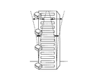
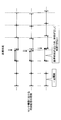
- FIG. 2 shows examples in which the sensor device 200 is installed in a building or a bridge.
- a sensor device having an acceleration sensor is provided for each floor of a building. With such a sensor device, the shaking of the building due to an earthquake can be observed for each floor.
- the sensor apparatus which has an acceleration sensor is provided in the various places of the bridge.
- sensor devices having a temperature sensor and sensor devices having a displacement sensor are provided at various locations on the bridge. As described above, these sensor devices 200 use the time information distributed from the distribution device 100 to execute the process of measuring the state at regular intervals and simultaneously (that is, synchronously).
- the distribution device 100 and the sensor device 200 are arranged in the same segment of the wired LAN and that no other device connection is connected on the network. Such a configuration provides time synchronization performance with a stable accuracy of 1 ms.
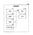
- FIG. 5 illustrates a hardware configuration example of the distribution apparatus 100 according to an embodiment of the present invention.
- the distribution apparatus 100 includes a CPU 11, ROM 12, RAM 13, HDD (Hard Disk Drive) / SSD (Solid State Drive) 14, NIC (Network Interface Card) 15, and RTC (Real Time Clock) 16.
- the CPU 11 executes a program that controls the operation of the distribution apparatus 100.
- the ROM 12 stores a system program executed by the CPU 11.
- the RAM 13 constitutes a work area for the CPU 11.
- the HDD / SSD 14 stores programs and data such as an OS and applications executed by the CPU 11.
- the NIC 15 includes a wired communication interface and its control device, and is used to communicate with the sensor device 200 and the server 300.
- the RTC 16 is a device for managing the local time.
- the bus 18 connects the above-described devices constituting the distribution device 100 to each other and exchanges data.
- the distribution apparatus 100 corrects the local time within a predetermined correction amount range with respect to the acquired reference time, and distributes the local time to the sensor device. Can do.
- the distribution apparatus 100 includes a wireless LAN module for performing communication with a wireless LAN together with or in place of the NIC 15, and a communication module for performing communication with Bluetooth (registered trademark) or ZigBee (registered trademark). May be. Although details will be described later, the distribution apparatus 100 may include a GPS receiver, an atomic clock, or a radio clock. The distribution apparatus 100 may include an input device such as a keyboard or a mouse that receives input from the user. Furthermore, the distribution apparatus 100 may include a display that presents information to the user. ⁇ 2.2 Sensor equipment ⁇ FIG. 6 illustrates a hardware configuration example of the sensor device 200 according to an embodiment of the present invention.
- the sensor device 200 in FIG. 6 is a configuration example of a sensor device having an acceleration sensor.
- the sensor device 200 includes a CPU 21, a ROM 22, a RAM 23, a NIC 24, an RTC 25, and an acceleration sensor 26.
- the CPU 21 executes a program for controlling the operation of the sensor device 200.
- the ROM 22 stores a program executed by the CPU 21.
- the RAM 23 constitutes a work area for the CPU 21.
- the NIC 24 includes a wired communication interface and its control device, and is used to communicate with the distribution device 100.
- the RTC 25 is a device for managing the local time.
- the acceleration sensor 26 is a device that detects acceleration applied to the sensor.
- the bus 27 connects the above-described devices constituting the sensor device 200 to each other and exchanges data.
- the sensor device 200 can correct the local time using the time information distributed from the distribution device 100 and execute predetermined processing at regular intervals.
- the sensor device 200 includes a wireless LAN module for performing communication with a wireless LAN together with or in place of the NIC 24 and a communication module for performing communication with Bluetooth (registered trademark) or ZigBee (registered trademark). May be. ⁇ 3. Functional configuration ⁇ Next, functional configurations of the distribution device 100 and the sensor device 200 according to an embodiment of the present invention will be described with reference to FIG. Note that FIG. 7 illustrates elements that are particularly relevant to the description of the present embodiment, among various elements included in the distribution device 100 and the sensor device 200.
- the distribution apparatus 100 includes a reference time acquisition unit 101, a local time management unit 102, a calculation unit 103, a correction unit 104, a time information distribution unit 105, a period information storage unit 151, and a correction amount information storage unit 152. And a threshold information storage unit 153.
- the period information storage unit 151, the correction amount information storage unit 152, and the threshold information storage unit 153 are realized by the HDD / SSD 14 of FIG.
- the cycle information storage unit 151 stores cycle information indicating a cycle T (unit: second) for distributing time information to the sensor device 200.
- the period T is determined in advance by the user by a parameter determination method described later.
- the correction amount information storage unit 152 stores correction amount information indicating a correction amount B that can correct the local time of the distribution apparatus 100 at a time.
- the correction amount B is determined in advance by the user by a parameter determination method described later.
- the correction amount B is determined according to the error tolerance range of the processing cycle of the sensor device 200.
- the threshold information storage unit 153 stores threshold information indicating a threshold S of a difference between the acquired reference time and the local time of the distribution apparatus 100.
- the threshold S is set to a value sufficiently larger than the correction amount B described above.
- the reference time acquisition unit 101 is realized mainly by the processing of the CPU 11 and the NIC 15, and acquires time information representing the reference time from the external server 300.
- the reference time acquisition unit 101 can acquire time information from the server 300 using, for example, an NTP client function.
- the reference time acquisition unit 101 can acquire time information from the server 300 using an arbitrary protocol.
- the reference time acquisition unit 101 may acquire the reference time by itself without acquiring the reference time from the server 300 via the NIC 15.
- the distribution device 100 may include a GPS receiver or a radio clock, and the reference time acquisition unit 101 may acquire the reference time through these devices.
- the reference time acquisition unit 101 can acquire the reference time at an arbitrary timing.
- the local time management unit 102 is realized mainly by the processing of the CPU 11 and the RTC 16, and manages the local time in the distribution apparatus 100.
- the local time may be held inside the distribution device or may be acquired from an external device.
- the calculation unit 103 is realized mainly by the processing of the CPU 11 and calculates a difference D between the reference time acquired by the reference time acquisition unit 101 and the local time acquired from the local time management unit 102.
- the correction unit 104 is realized mainly by the processing of the CPU 11, and determines how much the local time managed by the local time management unit 102 is corrected according to the magnitude of the difference D calculated by the calculation unit 103. At this time, the correction unit 104 refers to the correction amount information stored in the correction amount information storage unit 152 and the threshold information stored in the threshold information storage unit 153 to make a determination. And the correction
- Difference D ⁇ correction amount B adjust local time to reference time
- Correction amount B ⁇ difference D ⁇ threshold S make local time close to reference time within correction amount range
- threshold S ⁇ difference D Adjust local time to the reference time
- the local time management unit 102 manages immediately after the distribution apparatus 100 is started. The local time may be significantly different from the actual time, so the local time is adjusted to the reference time.
- the time information distribution unit 105 is realized mainly by the processing of the CPU 11 and the NIC 15.
- the time information distribution unit 105 refers to the period information stored by the period information storage unit 151 and distributes the time information including the local time managed by the local time management unit 102 to the sensor device 200 at a certain period T. To do.
- the time information distribution unit 105 distributes time information to the sensor device 200 using, for example, NTP.
- NTP When the NTP is used, the time information distribution unit 105 distributes the time information in response to the time distribution request transmitted from the sensor device 200.
- the distributed time information may be corrected as appropriate according to the propagation delay time of the network.
- a method for correcting the time information for example, a method described in Non-Patent Document 4 can be used.
- the time information distribution unit 105 can distribute time information to the sensor device 200 using an arbitrary protocol.
- time information distribution unit 105 holds the time when the time information was distributed immediately before, and sets the time obtained by adding the period T to the next time information distribution time.
- the distribution device 100 can distribute time information indicating the time corrected within a predetermined correction amount range to the sensor device 200. As a result, the sensor device 200 can continue to execute the measurement process within the range of the error tolerance of the process execution cycle.
- the sensor device 200 includes a time information reception unit 201, a local time management unit 202, a process execution unit 203, and a process result storage unit 251.
- the time information receiving unit 201 is realized mainly by the processing of the CPU 21 and the NIC 24, and receives the time information transmitted from the time information distributing unit 105 of the distribution device 100.
- the time information receiving unit 201 receives time information from the distribution apparatus 100 using, for example, NTP.
- the time information receiving unit 201 can receive time information from the distribution apparatus 100 using an arbitrary protocol.
- the local time management unit 202 is realized mainly by the processing of the CPU 21 and the RTC 25, and manages the local time of the sensor device 200.
- the local time management unit 202 adjusts the local time to the time indicated by the time information received by the time information receiving unit 201.
- the processing execution unit 203 is realized mainly by the processing of the CPU 21 and the acceleration sensor 26, and measures the acceleration applied to the acceleration sensor 26 at regular intervals. For example, in the case of measuring vibration derived from an earthquake applied to a structure, the process execution unit 203 executes acceleration measurement processing at intervals of about 5-10 milliseconds.
- the execution period of the processing is the purpose of measurement (detection of shaking due to earthquake, detection of abnormality of strength of buildings, etc.), structure to be measured (buildings, bridges, etc.), measurement data (vibration, strain, displacement, temperature) Etc.).
- the process execution unit 203 may execute not only the measurement process by the acceleration sensor process but also the measurement process by an arbitrary sensor at regular intervals. Moreover, the process execution part 203 may perform the general information processing which does not use a sensor at a fixed interval.
- the processing result storage unit 251 is realized by the ROM 22 of FIG. 6 and stores the processing result by the processing execution unit 203 together with the local time when the processing is executed.
- the sensor device 200 can execute the measurement process within a range that does not exceed the allowable error of the process execution cycle.
- the time information receiving unit 201 When receiving time information using NTP, the time information receiving unit 201 transmits a time distribution request to the distribution apparatus 100 according to a predetermined cycle, and receives time information as a response.
- the predetermined period is the same as the period indicated by the period information stored in the period information storage unit 151 of the distribution apparatus 100 in FIG. Therefore, as illustrated in FIG. 23, the sensor device 200 may include a cycle information storage unit 252 having the same function as the cycle information storage unit 151 of FIG. 7. That is, the time information receiving unit 201 can receive the time information from the distribution device 100 according to the cycle information stored in the cycle information storage unit 252. It is also possible to receive various information transmitted from the sensor device.
- the time information to be distributed may be corrected as appropriate according to the propagation delay time of the network.
- a method for correcting the time information for example, a method described in Non-Patent Document 4 can be used.
- ⁇ 4. Example of operation a processing flow of the distribution apparatus 100 and an operation example of the distribution system 1 according to an embodiment of the present invention will be described with reference to FIGS. Hereinafter, the processing of the distribution apparatus 100 will be described by dividing it into local time correction processing and time distribution processing.
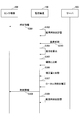
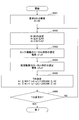
- FIG. 8 is a flowchart showing local time correction processing of distribution apparatus 100 according to an embodiment of the present invention.
- the reference time acquisition unit 101 acquires a reference time (step S101).
- the calculation unit 103 calculates a difference D between the reference time acquired in step S101 and the local time managed by the local time management unit 102 (step S102).
- the correction unit 104 determines how much the local time managed by the local time management unit 102 is to be corrected according to the magnitude of the difference D calculated in step S102.
- the distribution apparatus 100 is immediately after activation (that is, when the processing flow is executed for the first time after activation)
- the process proceeds to step S109 (Yes in step S103). Otherwise, the process proceeds to step S104 (No in step S103).
- the correction unit 104 compares the difference D calculated in step S102 with the threshold value S stored in the threshold value information storage unit 153 (step S104). If the difference D is greater than the threshold value S, the process proceeds to step S109 (Yes in step S105). Otherwise, the process proceeds to step S106 (No in step S105).
- the correction unit 104 compares the difference D calculated in step S102 with the correction amount B stored in the correction amount information storage unit 152 (step S106). If the difference D is greater than the correction amount B, the process proceeds to step S108 (Yes in step S107). Otherwise, the process proceeds to step S109 (No in step S107).
- step S108 the correction unit 104 corrects the local time within the correction amount range so that the local time approaches the reference time.
- FIG. 9 is a flowchart showing time distribution processing of the distribution apparatus 100 according to the embodiment of the present invention.
- the time information distribution unit 105 reads the local time managed by the local time management unit 102 (step S201).
- the time information distribution unit 105 reads the cycle information stored in the cycle information storage unit 151 (step S202).
- the time information distribution unit 105 determines whether the time obtained by adding the time when the time information was immediately distributed and the period T read in step S202 is equal to the local time read in step S201 (or the local time has passed). Judgment) As a result, if they are equal (or the local time has elapsed) (Yes in step S203), the process proceeds to step S204, and the time information distribution unit 105 distributes the time information indicating the local time to the sensor device 200. . On the other hand, if they are not equal (or if the local time has not elapsed), the process returns to step S201 (No in step S203).
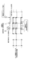
- FIG. 10 is a sequence diagram illustrating an operation example of the distribution system 1 according to the embodiment of the present invention. Here, typically only one sensor device 200 is shown.
- the time information distribution unit 105 of the distribution device 100 acquires the local time managed by the local time management unit 102, and transmits this local time to the time information reception unit 201 of the sensor device 200 as time information (step). S301).
- the time information distribution unit 105 of the distribution device 100 internally stores the time when the time information was distributed in step S301.
- the reference time acquisition unit 101 of the distribution apparatus 100 acquires the reference time from the server 300.
- the calculation unit 103 of the distribution apparatus 100 calculates a difference D between the reference time acquired in step S303 and the local time managed by the local time management unit 102 (step S304).
- the correction unit 104 of the distribution apparatus 100 compares the difference D calculated in step S304 with the threshold value S stored in the threshold value information storage unit 153 (step S305).
- the difference D is equal to or less than the threshold value S, and the process proceeds to the next process.
- the correction unit 104 of the distribution apparatus 100 compares the difference D calculated in step S304 with the correction amount B stored in the correction amount information storage unit 152 (step S306).
- the difference D is larger than the correction amount D, the process proceeds to the next process.
- the correcting unit 104 of the distribution apparatus 100 corrects the local time within the correction amount range so that the local time approaches the reference time acquired in step S303 (step S307).
- the time information distribution unit 105 of the distribution apparatus 100 detects that the local time corrected in step S307 has passed a time obtained by adding a period to the time stored in step S302.
- the time information is transmitted to the sensor device 200 (step S308).
- the time information distribution unit 105 of the distribution apparatus 100 internally stores the time at which the time information was distributed in step S308 (step S309).
- the distribution apparatus 100 can gradually correct the local time with respect to the reference time, and distribute the local time to the sensor device. .
- the sensor device that has received the local time can execute a predetermined process at a stable cycle.
- the correction unit 104 of the distribution apparatus 100 may further correct the local time without acquiring the reference time again after step S309.
- the difference D2 between the corrected local time of the distribution apparatus 100 and the reference time is an amount obtained by subtracting the correction amount of the local time in step S307 from the difference D calculated in step S304. Therefore, the correction
- ⁇ 5 Effect ⁇ Next, the effects obtained by the distribution apparatus 100 according to the embodiment of the present invention will be described with reference to FIGS. 11 to 15 and FIG.
- FIG. 11 shows how the distribution device 100 according to an embodiment of the present invention distributes time information to three sensor devices.
- the difference D between the reference time and the local time of the distribution apparatus 100 is within the range of the correction amount B (when (1) difference D ⁇ correction amount B described above).
- the reference time is advanced by a certain time with respect to the local time of the distribution apparatus 100 (difference D), but the difference is equal to or less than the correction amount B. Therefore, the local time is corrected to coincide with the reference time. Thereafter, the distribution apparatus 100 distributes the time information according to the corrected local time. Therefore, after each sensor device receives the time information, the processing cycle is temporarily shortened by the difference D.
- FIG. 12 schematically shows the distribution of time information by a conventional distribution device not according to the present invention.
- the difference D between the reference time and the local time of the distribution apparatus is not within the range of the correction amount B ((2) correction amount B ⁇ difference D ⁇ threshold value S).
- the distribution device not according to the present invention adjusts the local time to the reference time regardless of the difference between the reference time and the local time. Therefore, as a result of distributing the time information according to the corrected local time, the distribution apparatus 100 does not satisfy the request for the execution period of the processing by each sensor device.
- an example has been shown in which the reference time is ahead of the local time of the distribution apparatus 100, but the same applies when the reference time is behind the local time of the distribution apparatus 100.
- FIG. 13 schematically shows distribution of time information by the distribution apparatus 100 according to an embodiment of the present invention.
- the difference D between the reference time and the local time of the distribution apparatus is not within the range of the correction amount B ((2) correction amount B ⁇ difference D ⁇ threshold value S).
- the distribution apparatus 100 according to the embodiment of the present invention adjusts the local time to the reference time with the correction amount B as a limit. Therefore, for example, even if the accuracy of the reference time itself is insufficient or a communication delay between the server 300 that provides the reference time and the distribution device 100 occurs, the time information is sent to the sensor device while maintaining a certain period. Can be delivered. As a result, the sensor device can execute the measurement process at a stable cycle.
- FIG. 14 shows an example in which the reference time and the local time are synchronized by the distribution apparatus 100 according to the embodiment of the present invention further correcting the local time after the correction process shown in FIG. .
- the distribution apparatus 100 corrects the local time by the correction amount B so as to approach the acquired reference time. Thereafter, the distribution apparatus 100 corrects the local time again within the range of the correction amount B before acquiring the reference time again.
- the distribution apparatus 100 repeats the same processing until the local time matches the reference time. In this way, the distribution apparatus 100 can gradually adjust the local time within the range of the correction amount B to the reference time. As a result, the change in the time information distribution cycle falls within a certain range, and the sensor device can execute the measurement process at a stable cycle.
- FIG. 15 shows a conventional example in which the sensor device 200 acquires the reference time directly from the external server 300 or the like. As can be seen from the figure, the sensor device acquires the reference time from the external server 300 through each route. As a result, an error occurs in the time synchronization period and the time itself.
- FIG. 22 illustrates a state of time distribution when the distribution apparatus 100 and the sensor device perform time synchronization by NTP.
- the distribution apparatus 100 receives a time synchronization request from each sensor device after acquiring the reference time, and distributes time information to each sensor device.
- the distribution apparatus 100 or the sensor device corrects and uses time information in consideration of the propagation delay time of the network and the like. Thereby, a sensor apparatus can perform a measurement process with the stable period using NTP already prevailing.
- FIG. 16 shows a configuration example of a distribution system 1A different from the distribution system 1 shown in FIG.
- the distribution apparatus 100 acquires the reference time independently.
- the distribution apparatus 100 includes a GPS receiver or a radio clock. By setting it as such a structure, the structure of a delivery system can be simplified.
- FIG. 17 shows a configuration example of a distribution system 1B different from the distribution systems shown in FIGS.
- the distribution apparatus 100 can acquire the reference time independently.
- the distribution device 100 and the sensor device 200 of the distribution system 1B are connected by a signal line for transmitting a synchronous clock and a signal line for transmitting digital time information corresponding to the synchronous clock.
- time when time is distributed as a digital value, it is easily affected by variations in communication delay time.
- using a synchronous clock allows time to be distributed without receiving such a delay. ⁇ 7.
- the period T and the correction amount B are determined according to the following method before the distribution apparatus 100 and the sensor device 200 are installed, and are stored in the period information storage unit and the correction information storage unit as the period information and the correction amount information, respectively. Is done.
- the period T and the correction amount B are determined based on the tolerance of the sensor device to the time (or the tolerance of the processing execution cycle) and the accuracy of the local clock of the sensor device. How to do it.
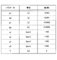
- the correction amount B includes a correction amount B1 (negative value, unit: second) for correcting the local time to be delayed, and a correction amount B2 (positive value, for correcting the local time to advance). (Unit: second) (
- step S301 when the measurement target of the sensor device 200 (for example, the degree of vibration of the structure due to the earthquake) is determined by the user, the allowable error with respect to the time of the sensor device (or the allowable error of the processing execution cycle). ) Is determined.
- the allowable error to the time of the sensor device is represented by A1 (unit: second) and A2 (unit: second).
- A1 is a negative value
- A2 (however, generally, if the minimum value of the allowable error is A1 and the maximum value is A2, the following equation holds).
- step S302 the correction amounts B1 and B2 are selected so as to be within the tolerances A1 and A2 of the time of the sensor device.
- the relationship among A1, A2, B1, and B2 is expressed by the following equation.
- the selected value is preferably selected.
- step S303 the accuracy of the local clock of the sensor device 200 is selected.
- the accuracy of the local timepiece of the sensor device 200 is determined by the performance of the RTC 25 mounted on the sensor device 200.
- the accuracy of the local clock is represented by x1 (negative value, unit: ppm, Parts per Million) and x2 (positive value, unit: ppm).
- x1 negative value
- x2 positive value
- both x1 and x2 may be a positive value or a negative value.
- step S304 a cycle T in which the distribution apparatus 100 distributes time information is determined.
- the period T needs to be selected so that the error of the local clock of the sensor device 200 accumulated during the period T does not exceed the allowable error with respect to the time of the sensor device 200. Therefore, the period T is selected so as to satisfy the following expression.
- step S305 when T selected in step S304 is an appropriate value in the configuration of the distribution system 1, this value is stored in the cycle information storage unit 151 as cycle information.
- T selected in step S304 is not an appropriate value (on the distribution system, if the time is distributed at period T, the processing load or the network load is too large), the process returns to step S303, and the accuracy of the local clock and the period T Is selected again.
- the distribution apparatus 100 performs stable time distribution within the allowable error range with respect to the time of the sensor device 200 or the execution period by using the period T and the correction amount B (B1, B2) obtained by the above method. be able to.
- FIG. 19 shows an example of each parameter selected by the above method.
- step S401 similar to step S301 of FIG. 18, tolerances to the time of the sensor device (or tolerances of processing execution cycles) A1 and A2 are determined.
- step S402 correction amounts B1 and B2 are selected as in step S302 of FIG.
- step S403 as in step S303 in FIG. 18, the precision x1 and x2 of the local clock of the sensor device 200 is selected.
- step S404 the accuracy of the local clock of the distribution apparatus 100 is selected.
- the accuracy of the local clock of the distribution apparatus 100 is determined by the performance of the RTC 16 mounted on the distribution apparatus 100.
- the accuracy of the local clock is represented by y1 (negative value, unit: ppm) and y2 (positive value, unit: ppm).
- y1 is a negative value
- y2 is a positive value
- both y1 and y2 may be a positive value or a negative value.
- step S405 a cycle T in which the distribution device 100 distributes time information is determined.
- the period T is selected so that the sum of the error of the local clock of the distribution apparatus 100 and the error of the local clock of the sensor device 200 does not exceed the allowable error with respect to the time of the sensor device 200 during the period T. Need to be done. Therefore, the period T is selected so as to satisfy the following expression.
- step S406 when T selected in step S405 is an appropriate value in the configuration of the distribution system 1, this value is stored in the cycle information storage unit 151 as cycle information. On the other hand, if T selected in step S405 is not an appropriate value, the process returns to step S402, and the correction amounts B1, B2, the accuracy x1, x2, y1, y2 of the local clock of the sensor device and the distribution device, and the period T Is selected again.
- the distribution apparatus 100 uses the period T and the correction amount B (B1, B2) obtained by the above method, and thereby distributes the time more stably within the allowable error range with respect to the time of the sensor device 200 or the execution period. It can be performed.
- FIG. 20 shows an example of each parameter selected by the above method.
- Distribution device 101 Reference time acquisition unit 102 Local time management unit 103 Calculation unit 104 Correction unit 105 Time information distribution unit 151 Period information storage unit 152 Correction amount information storage unit 153 Threshold information storage unit 200 Sensor device 201 Time information reception unit 202 Local time management unit 203 Processing execution unit 251 Processing result storage unit 300 Server
Landscapes
- Engineering & Computer Science (AREA)
- Theoretical Computer Science (AREA)
- Physics & Mathematics (AREA)
- General Engineering & Computer Science (AREA)
- General Physics & Mathematics (AREA)
- Computer Networks & Wireless Communication (AREA)
- Signal Processing (AREA)
- Electric Clocks (AREA)
- Arrangements For Transmission Of Measured Signals (AREA)
- Synchronisation In Digital Transmission Systems (AREA)
Abstract
Provided is a distribution device that distributes time information to one or more sensor apparatus and includes: storage that stores correction-amount information expressing a correction amount which corrects the distribution device local time in one sitting; an acquisition unit that acquires a reference time; a calculation unit that obtains the difference between the acquired reference time and the local time; a correction unit that corrects the local time by the correction amount when the obtained difference is larger than the correction amount; and a distributor that distributes time information expressing the corrected local time to the sensor apparatus.
Description
本発明は、配信装置、配信システム及び配信方法に関する。
The present invention relates to a distribution device, a distribution system, and a distribution method.
加速度センサや変位センサ等に代表されるセンサを備えたセンサ機器を、建屋や橋梁等の構造物に取付け、構造物の状態を監視する、モニタリング技術が知られている(非特許文献1)。モニタリング技術で利用されるセンサ機器は、一定の周期で、構造物の状態(加速度や位置等)の変化を検出する処理を実行する。当該処理の結果は、時刻情報と共に、当該センサ機器等に一時的に記録される。そして、記録された結果は、例えばネットワーク等を介して、外部の装置に送信される。
A monitoring technique is known in which a sensor device including a sensor represented by an acceleration sensor or a displacement sensor is attached to a structure such as a building or a bridge, and the state of the structure is monitored (Non-patent Document 1). A sensor device used in the monitoring technique executes a process of detecting a change in the state (acceleration, position, etc.) of the structure at a constant cycle. The result of the processing is temporarily recorded in the sensor device or the like together with time information. The recorded result is transmitted to an external device via a network or the like, for example.
センサ機器は、状態の変化を検出するための処理を、一定の周期で実行する。当該周期は、モニタリングの目的又は対象により、極めて短い周期となり得る。例えば、常時微動や地震に由来する振動を解析するためには、加速度センサが、5-10ミリ秒程度の一定の周期で、加速度を測定し続ける必要がある。
Sensor device executes processing for detecting a change in state at a constant cycle. The period can be a very short period depending on the purpose or object of monitoring. For example, in order to analyze vibrations caused by microtremors or earthquakes, it is necessary for the acceleration sensor to continue measuring acceleration at a constant cycle of about 5-10 milliseconds.
一方、センサ機器は、構造物に加わる振動等を感知して記録するために、外部から提供される時刻情報を用いて、時刻を同期する。これらのセンサ機器は、時刻を管理する外部の装置とネットワークで接続され、NTP(Network Time Protocol)や、RBS(Reference Broadcast Synchronization)といったプロトコルを用いて、時刻を同期する(非特許文献2、3)。NTPのようなプロトコルを用いる場合には、伝送遅延時間を考慮して、時刻情報を補正する技術が利用される(非特許文献4)。
On the other hand, the sensor device synchronizes the time using time information provided from the outside in order to detect and record vibrations applied to the structure. These sensor devices are connected to an external device for managing the time through a network, and synchronize the time using a protocol such as NTP (Network Time Protocol) or RBS (Reference Broadcast Synchronization) (Non-Patent Documents 2 and 3). ). When a protocol such as NTP is used, a technique for correcting time information in consideration of transmission delay time is used (Non-Patent Document 4).
特許文献1は、電波時計の受信機能を有する複数の機器が、標準電波により基準時刻を取得することにより、全ての機器の時刻を同期させる技術を開示している。
Patent Document 1 discloses a technology in which a plurality of devices having a reception function of a radio clock acquire the reference time by using a standard radio wave to synchronize the time of all devices.
特許文献2は、GPS由来の時刻と、安定的で高精度の原振クロック由来の時刻との差分の時間を用いて、時刻の補正量を決定し、Synchronous Ethernet(登録商標)を介して、互いに接続された基地局や通信装置の時刻同期を行う技術を開示している。
Patent Document 2 uses a difference time between a time derived from GPS and a time derived from a stable and highly accurate original oscillation clock to determine a correction amount of time, and through Synchronous Ethernet (registered trademark), A technique for performing time synchronization of base stations and communication devices connected to each other is disclosed.
特許文献3は、クライアントからサーバに送信された時刻同期要求が一定数に達したとき、NTPを用いて時刻同期を実行する、時刻同期システムを開示している。
Patent Document 3 discloses a time synchronization system that performs time synchronization using NTP when the number of time synchronization requests transmitted from a client to a server reaches a certain number.
特許文献4は、NTPクライアントから時刻同期要求を受け取ったNTPサーバが、NTPクライアントに対して判定情報を送信し、クライアントが判定情報を用いて時刻同期を行うか否かを判定する技術を開示している。
Patent Document 4 discloses a technique in which an NTP server that has received a time synchronization request from an NTP client transmits determination information to the NTP client, and the client determines whether to perform time synchronization using the determination information. ing.
例えばモニタリングに使用されるような機器は、外部の装置から提供される時刻情報を用いて、自らのローカル時計の時刻を補正する。そして、機器は、ローカル時刻を用いて、一定の周期で実行した処理の結果を記録する。
For example, a device used for monitoring corrects the time of its own local clock using time information provided from an external device. And an apparatus records the result of the process performed with the fixed period using local time.
ここで、従来の技術においては、外部の装置から提供される時刻情報の示す時刻と、機器のローカル時刻とが、大幅に異なる場合であっても、機器は、ローカル時刻の補正を実行する。その結果、機器による処理の結果が、一定の周期で記録されなくなり、後に結果の解析を行う際に、不都合を生ずる可能性がある。
Here, in the conventional technology, even when the time indicated by the time information provided from an external device and the local time of the device are significantly different, the device performs correction of the local time. As a result, the result of processing by the device is not recorded at a fixed period, and there is a possibility that inconvenience may occur when the result is analyzed later.
本発明は、このような問題に鑑みてなされたものであり、機器が安定した周期で処理を実行可能なように時刻情報を配信することを目的とする。
The present invention has been made in view of such a problem, and an object thereof is to distribute time information so that a device can execute processing at a stable cycle.
上述した課題を解決し目的を達成するため、本発明の一実施形態における配信装置は、
時刻情報を一以上の機器に配信する配信装置であって、
当該配信装置のローカル時刻を一度に補正する補正量を示す補正量情報を格納する格納部と、
基準時刻を取得する取得部と、
取得された前記基準時刻と、前記ローカル時刻との差分を求める算出部と、
求められた前記差分が、前記補正量より大きい場合に、前記補正量だけ前記ローカル時刻を補正する補正部と、
補正された前記ローカル時刻を示す時刻情報を前記機器に配信する配信部と、
を有する。 In order to solve the above-described problems and achieve the object, a distribution apparatus according to an embodiment of the present invention
A distribution device that distributes time information to one or more devices,
A storage unit that stores correction amount information indicating a correction amount for correcting the local time of the distribution device at a time;
An acquisition unit for acquiring a reference time;
A calculation unit for obtaining a difference between the acquired reference time and the local time;
A correction unit that corrects the local time by the correction amount when the obtained difference is larger than the correction amount;
A delivery unit that delivers time information indicating the corrected local time to the device;
Have
また、本発明の一実施形態における配信システムは、
一以上の機器と、時刻情報を前記機器に配信する配信装置とを含む配信システムであって、
前記配信装置は、
当該配信装置のローカル時刻を一度に補正する補正量を示す補正量情報を格納する格納部と、
基準時刻を取得する取得部と、
取得された前記基準時刻と、前記ローカル時刻との差分を求める算出部と、
求められた前記差分が、前記補正量より大きい場合に、前記補正量だけ前記ローカル時刻を補正する第一補正部と、
補正された前記ローカル時刻を示す時刻情報を前記機器に配信する配信部と、
を有し、
前記機器は、
前記配信部により配信された前記時刻情報を受信する受信部と、
受信した前記時刻情報の示す時刻と一致するように、当該機器のローカル時刻を補正する管理部と、
を有する。 The distribution system in one embodiment of the present invention is:
A distribution system including one or more devices and a distribution device that distributes time information to the devices,
The distribution device includes:
A storage unit that stores correction amount information indicating a correction amount for correcting the local time of the distribution device at a time;
An acquisition unit for acquiring a reference time;
A calculation unit for obtaining a difference between the acquired reference time and the local time;
A first correction unit that corrects the local time by the correction amount when the obtained difference is larger than the correction amount;
A delivery unit that delivers time information indicating the corrected local time to the device;
Have
The equipment is
A receiving unit that receives the time information distributed by the distributing unit;
A management unit that corrects the local time of the device so as to match the time indicated by the received time information;
Have
また、本発明の一実施形態における配信方法は、
時刻情報を一以上の機器に配信する配信方法であって、
基準時刻を取得する取得段階と、
取得された前記基準時刻と前記配信装置のローカル時刻との差分を求める算出段階と、
求められた前記差分が、前記ローカル時刻を一度に補正する補正量より大きい場合に、前記補正量だけ前記ローカル時刻を補正する補正段階と、
補正された前記ローカル時刻を示す時刻情報を前記機器に配信する配信段階と、
を有する。 In addition, the distribution method in one embodiment of the present invention is:
A distribution method for distributing time information to one or more devices,
An acquisition stage for acquiring a reference time;
A calculation step for obtaining a difference between the acquired reference time and the local time of the distribution device;
A correction step for correcting the local time by the correction amount when the obtained difference is larger than a correction amount for correcting the local time at a time;
A distribution stage of distributing time information indicating the corrected local time to the device;
Have
本発明によれば、機器が安定した周期で処理を実行可能なように時刻情報を配信できる。
According to the present invention, the time information can be distributed so that the device can execute the process at a stable cycle.
以下、本発明の実施形態を図面に基づいて説明する。
Hereinafter, embodiments of the present invention will be described with reference to the drawings.
1.システムの概要
2.ハードウェア構成
2.1 配信装置
2.2 センサ機器
3.機能構成
3.1 配信装置
3.2 センサ機器
4.動作例
4.1 ローカル時刻補正処理
4.2 時刻配信処理
4.3 配信システムの動作シーケンス
5.作用効果
6.変形例
7.パラメータの決定方法
≪ 1. システムの概要 ≫
図1は、本発明の一実施形態における配信システム1の概要を表す図である。配信システム1は、配信装置100と、一以上のセンサ機器200と、サーバ300とを含む。配信装置100は、インターネットやイントラネットのようなネットワークを介して、サーバ300と接続されている。また、配信装置100は、有線若しくは無線LAN(Local Area Network)、PAN(Personal Area Network)、又は専用の信号線等により、センサ機器200と接続されている。 1. 1.System overview 2. Hardware configuration 2.1 Distribution device 2.2 Sensor equipment Functional configuration 3.1 Distribution device 3.2 Sensor device 4. Operation example 4.1 Local time correction processing 4.2 Time distribution processing 4.3 Operation sequence of distribution system Function and effect 6. Modification 7 Parameter determination method << 1. System overview ≫
FIG. 1 is a diagram illustrating an overview of adistribution system 1 according to an embodiment of the present invention. The distribution system 1 includes a distribution device 100, one or more sensor devices 200, and a server 300. The distribution apparatus 100 is connected to the server 300 via a network such as the Internet or an intranet. The distribution apparatus 100 is connected to the sensor device 200 via a wired or wireless LAN (Local Area Network), a PAN (Personal Area Network), a dedicated signal line, or the like.
2.ハードウェア構成
2.1 配信装置
2.2 センサ機器
3.機能構成
3.1 配信装置
3.2 センサ機器
4.動作例
4.1 ローカル時刻補正処理
4.2 時刻配信処理
4.3 配信システムの動作シーケンス
5.作用効果
6.変形例
7.パラメータの決定方法
≪ 1. システムの概要 ≫
図1は、本発明の一実施形態における配信システム1の概要を表す図である。配信システム1は、配信装置100と、一以上のセンサ機器200と、サーバ300とを含む。配信装置100は、インターネットやイントラネットのようなネットワークを介して、サーバ300と接続されている。また、配信装置100は、有線若しくは無線LAN(Local Area Network)、PAN(Personal Area Network)、又は専用の信号線等により、センサ機器200と接続されている。 1. 1.
FIG. 1 is a diagram illustrating an overview of a
サーバ300は、例えば、サーバ用途向けのコンピュータにより構成される。サーバ300は、例えばNTPを用いて、正確な現在時刻を示す時刻情報を、配信装置100に提供する。例えば、サーバ300は、GPS(Global Positioning System)衛星から受信した電波を用いて、正確な現在時刻を取得することができる。また、サーバ300は、送信局から受信した標準電波により、正確な現在時刻を取得してもよい。また、サーバ300は、筐体の内部に備える原子時計を用いて正確な現在時刻を取得してもよい。また、サーバ300は、外部のNTPサーバと時刻同期することにより、正確な現在時刻を取得してもよい。サーバ300は、上述した手段を用いて正確な現在時刻を取得し、その時刻を示す時刻情報を、配信装置100に提供する。なお、以下では、上述した手段により取得された正確な現在時刻を、「基準時刻」と呼ぶ。
The server 300 is constituted by a computer for server use, for example. The server 300 provides time information indicating an accurate current time to the distribution apparatus 100 using, for example, NTP. For example, the server 300 can acquire an accurate current time using radio waves received from a GPS (Global Positioning System) satellite. Further, the server 300 may acquire the correct current time from the standard radio wave received from the transmitting station. In addition, the server 300 may acquire an accurate current time using an atomic clock provided in the housing. The server 300 may acquire the correct current time by synchronizing the time with an external NTP server. The server 300 acquires an accurate current time using the above-described means, and provides time information indicating the time to the distribution apparatus 100. Hereinafter, the accurate current time acquired by the above-described means is referred to as “reference time”.
配信装置100は、サーバ300から提供された基準時刻を用いて、配信装置100の備えるローカル時計の時刻(以下、ローカル時刻とする)を補正する。そして、配信装置100は、一定の周期で、ローカル時刻を示す時刻情報を、センサ機器200に配信する。
The distribution apparatus 100 corrects the time of a local clock (hereinafter referred to as local time) provided in the distribution apparatus 100 using the reference time provided from the server 300. Then, the distribution device 100 distributes time information indicating the local time to the sensor device 200 at a constant cycle.
ここで、配信装置100は、取得された基準時刻に対して、ローカル時刻を一度に補正できる最大量(以下、補正量とする)を予め保持している。従って、サーバ300から新たに受信した基準時刻と、ローカル時刻との差分が、補正量より大きい場合には、配信装置100は、ローカル時刻を、補正量の範囲内で進めた(あるいは遅らせた)時刻を、新たなローカル時刻とする。
Here, the distribution apparatus 100 holds in advance a maximum amount (hereinafter referred to as a correction amount) that can correct the local time at once with respect to the acquired reference time. Therefore, when the difference between the reference time newly received from the server 300 and the local time is larger than the correction amount, the distribution apparatus 100 advances (or delays) the local time within the range of the correction amount. Let the time be the new local time.
例えば、補正量が0.0002秒であり、ローカル時刻が12:00:00.0000である場合に、取得された基準時刻が12:00:00.0020であるとき、ローカル時刻は、「12:00:00.0001」又は「12:00:00.0002」に補正される。また、補正量が0.0002秒であり、ローカル時刻が12:00:00.0000である場合に、取得された基準時刻が11:59:59.9980であるとき、ローカル時刻は、「11:59:59.9998」又は「11:59:59.9999」に補正される。
For example, when the correction amount is 0.0002 seconds and the local time is 12: 00: 00.0000, and the acquired reference time is 12: 00: 00.0020, the local time is “12: 00: 00.0001” or It is corrected to “12: 00: 00.0002”. Further, when the correction amount is 0.0002 seconds and the local time is 12: 00: 00.0000, and the acquired reference time is 11: 59: 59.9980, the local time is “11: 59: 59.9998” or It is corrected to “11: 59: 59.9999”.
センサ機器200は、加速度センサ、変位センサ、歪センサ又は温度センサ等のセンサを有し、一定の間隔で、それらセンサによる状態の取得処理を実行する。また、センサ機器200は、配信装置100から配信された時刻情報を用いて、センサ機器200の備えるローカル時計の時刻を補正する。すなわち、センサ機器200は、配信装置100によって補正された時刻に従って、各処理を実行することにより、安定した時間間隔で、処理を実行し続けることができる。すなわち、配信装置100とセンサ機器200のローカル時刻が大幅に補正されることにより、処理の結果が記録されない期間ができてしまう問題を回避することができる。これは、一定間隔の測定データを必要とする解析処理を行う上で、好都合である。また、センサ機器が複数ある場合、一定間隔かつ同時に同期してデータを測定することができるという利点がある。
The sensor device 200 includes a sensor such as an acceleration sensor, a displacement sensor, a strain sensor, or a temperature sensor, and executes state acquisition processing using these sensors at regular intervals. Further, the sensor device 200 corrects the time of the local clock included in the sensor device 200 using the time information distributed from the distribution device 100. That is, the sensor device 200 can continue to execute the process at a stable time interval by executing each process according to the time corrected by the distribution apparatus 100. That is, it is possible to avoid a problem that a period in which the result of the process is not recorded is created by significantly correcting the local time of the distribution apparatus 100 and the sensor device 200. This is convenient for performing analysis processing that requires measurement data at regular intervals. Further, when there are a plurality of sensor devices, there is an advantage that data can be measured at a constant interval and simultaneously in synchronization.
なお、図2、図3、図4は、センサ機器200が、建屋や橋梁に設置された例を表す。図2では、加速度センサを有するセンサ機器が、ビルのフロアごとに設けられている。このようなセンサ機器により、地震によるビルの揺れを、フロアごとに観測することができる。また、図3では、橋の揺れを観測するため、加速度センサを有するセンサ機器が、橋の各所に設けられている。さらに、図4では、橋の強度や歪み等を観測するため、温度センサを有するセンサ機器や、変位センサを有するセンサ機器が、橋の各所に設けられている。これらのセンサ機器200は、上述したように、配信装置100から配信される時刻情報を用いて、状態を測定する処理を一定間隔かつ同時に(すなわち、同期して)実行する。
2, 3, and 4 show examples in which the sensor device 200 is installed in a building or a bridge. In FIG. 2, a sensor device having an acceleration sensor is provided for each floor of a building. With such a sensor device, the shaking of the building due to an earthquake can be observed for each floor. Moreover, in FIG. 3, in order to observe the shaking of a bridge, the sensor apparatus which has an acceleration sensor is provided in the various places of the bridge. Furthermore, in FIG. 4, in order to observe the strength, strain, and the like of the bridge, sensor devices having a temperature sensor and sensor devices having a displacement sensor are provided at various locations on the bridge. As described above, these sensor devices 200 use the time information distributed from the distribution device 100 to execute the process of measuring the state at regular intervals and simultaneously (that is, synchronously).
また、配信装置100とセンサ機器200は、有線LANの同一セグメント内に配置され、かつ、ネットワーク上に他の機器接続を接続しない構成とすることが、特に好ましい。このような構成は、安定した精度1msの時刻同期性能をもたらす。
Further, it is particularly preferable that the distribution device 100 and the sensor device 200 are arranged in the same segment of the wired LAN and that no other device connection is connected on the network. Such a configuration provides time synchronization performance with a stable accuracy of 1 ms.
以下、上記の配信システム1を構成する要素を詳細に説明する。
≪ 2. ハードウェア構成 ≫
図5、図6を用いて、本発明の一実施形態における配信装置100及びセンサ機器200のハードウェア構成例を説明する。
≪ 2.1 配信装置 ≫
図5は、本発明の一実施形態における配信装置100のハードウェア構成例を表す。配信装置100は、CPU11と、ROM12と、RAM13と、HDD(Hard Disk Drive)/SSD(Solid State Drive)14と、NIC(Network Interface Card)15と、RTC(Real Time Clock)16とを有する。 Hereinafter, the elements constituting thedistribution system 1 will be described in detail.
≪ 2. Hardware configuration ≫
A hardware configuration example of thedistribution device 100 and the sensor device 200 according to the embodiment of the present invention will be described with reference to FIGS. 5 and 6.
≪ 2.1 Distribution device ≫
FIG. 5 illustrates a hardware configuration example of thedistribution apparatus 100 according to an embodiment of the present invention. The distribution apparatus 100 includes a CPU 11, ROM 12, RAM 13, HDD (Hard Disk Drive) / SSD (Solid State Drive) 14, NIC (Network Interface Card) 15, and RTC (Real Time Clock) 16.
≪ 2. ハードウェア構成 ≫
図5、図6を用いて、本発明の一実施形態における配信装置100及びセンサ機器200のハードウェア構成例を説明する。
≪ 2.1 配信装置 ≫
図5は、本発明の一実施形態における配信装置100のハードウェア構成例を表す。配信装置100は、CPU11と、ROM12と、RAM13と、HDD(Hard Disk Drive)/SSD(Solid State Drive)14と、NIC(Network Interface Card)15と、RTC(Real Time Clock)16とを有する。 Hereinafter, the elements constituting the
≪ 2. Hardware configuration ≫
A hardware configuration example of the
≪ 2.1 Distribution device ≫
FIG. 5 illustrates a hardware configuration example of the
CPU11は、配信装置100の動作制御を行うプログラムを実行する。ROM12は、CPU11が実行するシステムプログラムを記憶する。RAM13は、CPU11のワークエリアを構成する。HDD/SSD14は、CPU11が実行するOSやアプリケーション等のプログラムやデータ等を記憶する。NIC15は、有線の通信インターフェースとその制御装置を含み、センサ機器200やサーバ300と通信を行うために用いられる。RTC16は、ローカル時刻を管理するための装置である。バス18は、当該配信装置100を構成する上記の装置を相互に接続し、データのやり取りを行う。
The CPU 11 executes a program that controls the operation of the distribution apparatus 100. The ROM 12 stores a system program executed by the CPU 11. The RAM 13 constitutes a work area for the CPU 11. The HDD / SSD 14 stores programs and data such as an OS and applications executed by the CPU 11. The NIC 15 includes a wired communication interface and its control device, and is used to communicate with the sensor device 200 and the server 300. The RTC 16 is a device for managing the local time. The bus 18 connects the above-described devices constituting the distribution device 100 to each other and exchanges data.
上記構成により、本発明の一実施形態における配信装置100は、取得した基準時刻に対して、予め定められた補正量の範囲内でローカル時刻を補正し、そのローカル時刻をセンサ機器に配信することができる。
With the above configuration, the distribution apparatus 100 according to an embodiment of the present invention corrects the local time within a predetermined correction amount range with respect to the acquired reference time, and distributes the local time to the sensor device. Can do.
なお、配信装置100は、NIC15と共に、又はNIC15に代えて、無線LANにより通信を行うための無線LANモジュールや、Bluetooth(登録商標)若しくはZigBee(登録商標)により通信を行うための通信モジュールを有してもよい。また、詳細は後述するが、配信装置100が、GPS受信機、原子時計又は電波時計を有していてもよい。また、配信装置100は、ユーザからの入力を受け付ける、キーボードやマウスのような、入力装置を備えていてもよい。さらに、配信装置100は、ユーザに対して情報を提示する、ディスプレイを備えていてもよい。
≪ 2.2 センサ機器 ≫
図6は、本発明の一実施形態におけるセンサ機器200のハードウェア構成例を表す。図6のセンサ機器200は、加速度センサを有する場合のセンサ機器の構成例である。センサ機器200は、CPU21と、ROM22と、RAM23と、NIC24と、RTC25と、加速度センサ26とを有する。 Thedistribution apparatus 100 includes a wireless LAN module for performing communication with a wireless LAN together with or in place of the NIC 15, and a communication module for performing communication with Bluetooth (registered trademark) or ZigBee (registered trademark). May be. Although details will be described later, the distribution apparatus 100 may include a GPS receiver, an atomic clock, or a radio clock. The distribution apparatus 100 may include an input device such as a keyboard or a mouse that receives input from the user. Furthermore, the distribution apparatus 100 may include a display that presents information to the user.
≪ 2.2 Sensor equipment ≫
FIG. 6 illustrates a hardware configuration example of thesensor device 200 according to an embodiment of the present invention. The sensor device 200 in FIG. 6 is a configuration example of a sensor device having an acceleration sensor. The sensor device 200 includes a CPU 21, a ROM 22, a RAM 23, a NIC 24, an RTC 25, and an acceleration sensor 26.
≪ 2.2 センサ機器 ≫
図6は、本発明の一実施形態におけるセンサ機器200のハードウェア構成例を表す。図6のセンサ機器200は、加速度センサを有する場合のセンサ機器の構成例である。センサ機器200は、CPU21と、ROM22と、RAM23と、NIC24と、RTC25と、加速度センサ26とを有する。 The
≪ 2.2 Sensor equipment ≫
FIG. 6 illustrates a hardware configuration example of the
CPU21は、センサ機器200の動作制御を行うプログラムを実行する。ROM22は、CPU21が実行するプログラムを記憶する。RAM23は、CPU21のワークエリアを構成する。NIC24は、有線の通信インターフェースとその制御装置を含み、配信装置100と通信を行うために用いられる。RTC25は、ローカル時刻を管理するための装置である。加速度センサ26は、当該センサにかかる加速度を検出する装置である。バス27は、当該センサ機器200を構成する上記の装置を相互に接続し、データのやり取りを行う。
The CPU 21 executes a program for controlling the operation of the sensor device 200. The ROM 22 stores a program executed by the CPU 21. The RAM 23 constitutes a work area for the CPU 21. The NIC 24 includes a wired communication interface and its control device, and is used to communicate with the distribution device 100. The RTC 25 is a device for managing the local time. The acceleration sensor 26 is a device that detects acceleration applied to the sensor. The bus 27 connects the above-described devices constituting the sensor device 200 to each other and exchanges data.
上記構成により、本発明の一実施形態におけるセンサ機器200は、配信装置100から配信された時刻情報を用いて、ローカル時刻を補正し、所定の処理を一定間隔で実行することができる。
With the above configuration, the sensor device 200 according to an embodiment of the present invention can correct the local time using the time information distributed from the distribution device 100 and execute predetermined processing at regular intervals.
なお、センサ機器200は、NIC24と共に、又はNIC24に代えて、無線LANにより通信を行うための無線LANモジュールや、Bluetooth(登録商標)若しくはZigBee(登録商標)により通信を行うための通信モジュールを有してもよい。
≪ 3. 機能構成 ≫
次に、図7を用いて、本発明の一実施形態における配信装置100及びセンサ機器200の機能構成を説明する。なお、図7には、配信装置100及びセンサ機器200が備える様々な要素のうち、本実施形態の説明に特に関連する要素が示されている。
≪ 3.1 配信装置 ≫
配信装置100は、基準時刻取得部101と、ローカル時刻管理部102と、算出部103と、補正部104と、時刻情報配信部105と、周期情報格納部151と、補正量情報格納部152と、閾値情報格納部153とを有する。このうち、周期情報格納部151と、補正量情報格納部152と、閾値情報格納部153は、図5のHDD/SSD14により実現される。 Thesensor device 200 includes a wireless LAN module for performing communication with a wireless LAN together with or in place of the NIC 24 and a communication module for performing communication with Bluetooth (registered trademark) or ZigBee (registered trademark). May be.
≪ 3. Functional configuration ≫
Next, functional configurations of thedistribution device 100 and the sensor device 200 according to an embodiment of the present invention will be described with reference to FIG. Note that FIG. 7 illustrates elements that are particularly relevant to the description of the present embodiment, among various elements included in the distribution device 100 and the sensor device 200.
≪ 3.1 Distribution device ≫
Thedistribution apparatus 100 includes a reference time acquisition unit 101, a local time management unit 102, a calculation unit 103, a correction unit 104, a time information distribution unit 105, a period information storage unit 151, and a correction amount information storage unit 152. And a threshold information storage unit 153. Among these, the period information storage unit 151, the correction amount information storage unit 152, and the threshold information storage unit 153 are realized by the HDD / SSD 14 of FIG.
≪ 3. 機能構成 ≫
次に、図7を用いて、本発明の一実施形態における配信装置100及びセンサ機器200の機能構成を説明する。なお、図7には、配信装置100及びセンサ機器200が備える様々な要素のうち、本実施形態の説明に特に関連する要素が示されている。
≪ 3.1 配信装置 ≫
配信装置100は、基準時刻取得部101と、ローカル時刻管理部102と、算出部103と、補正部104と、時刻情報配信部105と、周期情報格納部151と、補正量情報格納部152と、閾値情報格納部153とを有する。このうち、周期情報格納部151と、補正量情報格納部152と、閾値情報格納部153は、図5のHDD/SSD14により実現される。 The
≪ 3. Functional configuration ≫
Next, functional configurations of the
≪ 3.1 Distribution device ≫
The
周期情報格納部151は、時刻情報をセンサ機器200に配信する周期T(単位:秒)を示す周期情報を格納する。周期Tは、後述するパラメータ決定方法によって、ユーザにより予め決定される。
The cycle information storage unit 151 stores cycle information indicating a cycle T (unit: second) for distributing time information to the sensor device 200. The period T is determined in advance by the user by a parameter determination method described later.
補正量情報格納部152は、当該配信装置100のローカル時刻を一度に補正できる補正量Bを示す補正量情報を格納する。補正量Bは、後述するパラメータ決定方法によって、ユーザにより予め決定される。補正量Bは、センサ機器200の処理の実行周期の、誤差の許容範囲に応じて、決定される。
The correction amount information storage unit 152 stores correction amount information indicating a correction amount B that can correct the local time of the distribution apparatus 100 at a time. The correction amount B is determined in advance by the user by a parameter determination method described later. The correction amount B is determined according to the error tolerance range of the processing cycle of the sensor device 200.
閾値情報格納部153は、取得された基準時刻と、当該配信装置100のローカル時刻との差分の閾値Sを示す閾値情報を格納する。取得された基準時刻と、ローカル時刻との差分が、閾値Sより大きい場合、ローカル時刻は、取得された基準時刻に合わせて補正してもよい。これは、基準時刻とローカル時刻との差分が著しく大きい場合には、センサ機器200の処理結果とともに記録される時刻が、実際の時刻と乖離し、後の分析に支障をきたす可能性があるためである。したがって、閾値Sは、上述した補正量Bより十分大きい値が設定される。
The threshold information storage unit 153 stores threshold information indicating a threshold S of a difference between the acquired reference time and the local time of the distribution apparatus 100. When the difference between the acquired reference time and the local time is larger than the threshold S, the local time may be corrected according to the acquired reference time. This is because when the difference between the reference time and the local time is remarkably large, the time recorded together with the processing result of the sensor device 200 may deviate from the actual time, which may hinder later analysis. It is. Accordingly, the threshold S is set to a value sufficiently larger than the correction amount B described above.
基準時刻取得部101は、主にCPU11及びNIC15の処理によって実現され、外部のサーバ300から、基準時刻を表す時刻情報を取得する。基準時刻取得部101は、例えば、NTPクライアントの機能を用いて、サーバ300から、時刻情報を取得することができる。基準時刻取得部101は、任意のプロトコルを用いて、サーバ300から、時刻情報を取得することができる。
The reference time acquisition unit 101 is realized mainly by the processing of the CPU 11 and the NIC 15, and acquires time information representing the reference time from the external server 300. The reference time acquisition unit 101 can acquire time information from the server 300 using, for example, an NTP client function. The reference time acquisition unit 101 can acquire time information from the server 300 using an arbitrary protocol.
なお、詳しくは後述するが、基準時刻取得部101は、NIC15を介して、サーバ300から基準時刻を取得することなく、自ら基準時刻を取得してもよい。例えば、配信装置100が、GPS受信機又は電波時計を備えており、基準時刻取得部101は、これらの装置を通じて、基準時刻を取得してもよい。
As will be described in detail later, the reference time acquisition unit 101 may acquire the reference time by itself without acquiring the reference time from the server 300 via the NIC 15. For example, the distribution device 100 may include a GPS receiver or a radio clock, and the reference time acquisition unit 101 may acquire the reference time through these devices.
また、基準時刻取得部101は、任意のタイミングで、基準時刻を取得することができる。
Moreover, the reference time acquisition unit 101 can acquire the reference time at an arbitrary timing.
ローカル時刻管理部102は、主にCPU11及びRTC16の処理によって実現され、当該配信装置100内のローカル時刻を管理する。ローカル時刻は、当該配信装置の内部で保持されてもよいし、外部の装置から取得されてもよい。
The local time management unit 102 is realized mainly by the processing of the CPU 11 and the RTC 16, and manages the local time in the distribution apparatus 100. The local time may be held inside the distribution device or may be acquired from an external device.
算出部103は、主にCPU11の処理によって実現され、基準時刻取得部101により取得された基準時刻と、ローカル時刻管理部102から取得されたローカル時刻との差分Dを算出する。
The calculation unit 103 is realized mainly by the processing of the CPU 11 and calculates a difference D between the reference time acquired by the reference time acquisition unit 101 and the local time acquired from the local time management unit 102.
補正部104は、主にCPU11の処理によって実現され、算出部103によって算出された差分Dの大きさに応じて、ローカル時刻管理部102によって管理されるローカル時刻をどの程度補正するか決定する。このとき、補正部104は、補正量情報格納部152に格納された補正量情報と、閾値情報格納部153に格納された閾値情報とを参照し、決定を行う。そして、補正部104は、以下の条件に従って、ローカル時刻を補正する。
(1)差分D≦補正量B :ローカル時刻を基準時刻に合わせる
(2)補正量B<差分D≦閾値S:ローカル時刻を補正量の範囲内で基準時刻に近づける
(3)閾値S<差分D :ローカル時刻を基準時刻に合わせる
(4)配信装置の起動直後 :ローカル時刻を基準時刻に合わせる
なお、(4)に示すように、配信装置100の起動直後は、ローカル時刻管理部102によって管理されるローカル時刻が、実際の時刻と大きくずれている可能性があるため、ローカル時刻を基準時刻に合わせる。 Thecorrection unit 104 is realized mainly by the processing of the CPU 11, and determines how much the local time managed by the local time management unit 102 is corrected according to the magnitude of the difference D calculated by the calculation unit 103. At this time, the correction unit 104 refers to the correction amount information stored in the correction amount information storage unit 152 and the threshold information stored in the threshold information storage unit 153 to make a determination. And the correction | amendment part 104 correct | amends local time according to the following conditions.
(1) Difference D ≦ correction amount B: adjust local time to reference time (2) Correction amount B <difference D ≦ threshold S: make local time close to reference time within correction amount range (3) threshold S <difference D: Adjust local time to the reference time (4) Immediately after starting the distribution apparatus: Adjust local time to the reference time Note that, as shown in (4), the localtime management unit 102 manages immediately after the distribution apparatus 100 is started. The local time may be significantly different from the actual time, so the local time is adjusted to the reference time.
(1)差分D≦補正量B :ローカル時刻を基準時刻に合わせる
(2)補正量B<差分D≦閾値S:ローカル時刻を補正量の範囲内で基準時刻に近づける
(3)閾値S<差分D :ローカル時刻を基準時刻に合わせる
(4)配信装置の起動直後 :ローカル時刻を基準時刻に合わせる
なお、(4)に示すように、配信装置100の起動直後は、ローカル時刻管理部102によって管理されるローカル時刻が、実際の時刻と大きくずれている可能性があるため、ローカル時刻を基準時刻に合わせる。 The
(1) Difference D ≦ correction amount B: adjust local time to reference time (2) Correction amount B <difference D ≦ threshold S: make local time close to reference time within correction amount range (3) threshold S <difference D: Adjust local time to the reference time (4) Immediately after starting the distribution apparatus: Adjust local time to the reference time Note that, as shown in (4), the local
時刻情報配信部105は、主にCPU11及びNIC15の処理によって実現される。時刻情報配信部105は、周期情報格納部151によって格納される周期情報を参照し、一定の周期Tで、ローカル時刻管理部102によって管理されるローカル時刻を含む時刻情報を、センサ機器200に配信する。時刻情報配信部105は、例えば、NTPを用いて、センサ機器200に時刻情報を配信する。時刻情報配信部105は、NTPを用いる場合には、センサ機器200から送信された時刻配信要求に応じて、時刻情報を配信する。ここで、配信される時刻情報は、ネットワークの伝播遅延時間に応じて、適宜補正されてもよい。時刻情報を補正する手法は、例えば、非特許文献4に記載されている方法を用いることができる。時刻情報配信部105は、任意のプロトコルを用いて、センサ機器200に時刻情報を配信することができる。
The time information distribution unit 105 is realized mainly by the processing of the CPU 11 and the NIC 15. The time information distribution unit 105 refers to the period information stored by the period information storage unit 151 and distributes the time information including the local time managed by the local time management unit 102 to the sensor device 200 at a certain period T. To do. The time information distribution unit 105 distributes time information to the sensor device 200 using, for example, NTP. When the NTP is used, the time information distribution unit 105 distributes the time information in response to the time distribution request transmitted from the sensor device 200. Here, the distributed time information may be corrected as appropriate according to the propagation delay time of the network. As a method for correcting the time information, for example, a method described in Non-Patent Document 4 can be used. The time information distribution unit 105 can distribute time information to the sensor device 200 using an arbitrary protocol.
なお、時刻情報配信部105は、直前に時刻情報を配信した時刻を保持しておき、その時刻に周期Tを加えた時刻を、次回の時刻情報の配信時刻とする。
Note that the time information distribution unit 105 holds the time when the time information was distributed immediately before, and sets the time obtained by adding the period T to the next time information distribution time.
以上の機能により、本発明の一実施形態における配信装置100は、予め定められた補正量の範囲で補正された時刻を示す時刻情報を、センサ機器200に配信することができる。その結果、センサ機器200は、処理の実行周期の誤差許容量の範囲内で、測定処理を実行し続けることができる。
≪ 3.2 センサ機器 ≫
センサ機器200は、時刻情報受信部201と、ローカル時刻管理部202と、処理実行部203と、処理結果格納部251とを有する。 With the above function, thedistribution device 100 according to an embodiment of the present invention can distribute time information indicating the time corrected within a predetermined correction amount range to the sensor device 200. As a result, the sensor device 200 can continue to execute the measurement process within the range of the error tolerance of the process execution cycle.
≪ 3.2 Sensor equipment ≫
Thesensor device 200 includes a time information reception unit 201, a local time management unit 202, a process execution unit 203, and a process result storage unit 251.
≪ 3.2 センサ機器 ≫
センサ機器200は、時刻情報受信部201と、ローカル時刻管理部202と、処理実行部203と、処理結果格納部251とを有する。 With the above function, the
≪ 3.2 Sensor equipment ≫
The
時刻情報受信部201は、主にCPU21及びNIC24の処理によって実現され、配信装置100の時刻情報配信部105から送信された時刻情報を受信する。時刻情報受信部201は、例えば、NTPを用いて、配信装置100から時刻情報を受信する。時刻情報受信部201は、任意のプロトコルを用いて、配信装置100から時刻情報を受信することができる。
The time information receiving unit 201 is realized mainly by the processing of the CPU 21 and the NIC 24, and receives the time information transmitted from the time information distributing unit 105 of the distribution device 100. The time information receiving unit 201 receives time information from the distribution apparatus 100 using, for example, NTP. The time information receiving unit 201 can receive time information from the distribution apparatus 100 using an arbitrary protocol.
ローカル時刻管理部202は、主にCPU21及びRTC25の処理によって実現され、当該センサ機器200のローカル時刻を管理する。ローカル時刻管理部202は、ローカル時刻を、時刻情報受信部201によって受信された時刻情報の示す時刻に合わせる。
The local time management unit 202 is realized mainly by the processing of the CPU 21 and the RTC 25, and manages the local time of the sensor device 200. The local time management unit 202 adjusts the local time to the time indicated by the time information received by the time information receiving unit 201.
処理実行部203は、主にCPU21及び加速度センサ26の処理によって実現され、一定の間隔で、加速度センサ26に加わる加速度を測定する。例えば、構造物に加わる、地震に由来する振動を測定する場合には、処理実行部203は、5-10ミリ秒程度の間隔で、加速度の測定処理を実行する。処理の実行周期は、測定の目的(地震による揺れの検知、建物等の強度の異常の検知等)、測定対象となる構造物(建屋、橋梁等)、測定データ(振動、歪み、変位、温度等)によって異なり得る。
The processing execution unit 203 is realized mainly by the processing of the CPU 21 and the acceleration sensor 26, and measures the acceleration applied to the acceleration sensor 26 at regular intervals. For example, in the case of measuring vibration derived from an earthquake applied to a structure, the process execution unit 203 executes acceleration measurement processing at intervals of about 5-10 milliseconds. The execution period of the processing is the purpose of measurement (detection of shaking due to earthquake, detection of abnormality of strength of buildings, etc.), structure to be measured (buildings, bridges, etc.), measurement data (vibration, strain, displacement, temperature) Etc.).
なお、処理実行部203は、加速度センサの処理による測定処理だけでなく、任意のセンサによる測定処理を、一定の間隔で実行してもよい。また、処理実行部203は、センサを使用しない一般的な情報処理を、一定の間隔で実行してもよい。
Note that the process execution unit 203 may execute not only the measurement process by the acceleration sensor process but also the measurement process by an arbitrary sensor at regular intervals. Moreover, the process execution part 203 may perform the general information processing which does not use a sensor at a fixed interval.
処理結果格納部251は、図6のROM22により実現され、処理実行部203による処理の結果を、その処理が実行されたローカル時刻とともに格納する。
The processing result storage unit 251 is realized by the ROM 22 of FIG. 6 and stores the processing result by the processing execution unit 203 together with the local time when the processing is executed.
以上の機能により、本発明の一実施形態におけるセンサ機器200は、処理の実行周期の誤差許容量を超えない範囲で、測定処理を実行することができる。
With the above function, the sensor device 200 according to the embodiment of the present invention can execute the measurement process within a range that does not exceed the allowable error of the process execution cycle.
なお、時刻情報受信部201は、NTPを用いて時刻情報を受信する場合には、所定の周期に従って、配信装置100へと時刻配信要求を送信し、その応答として、時刻情報を受信する。所定の周期は、図7の配信装置100の周期情報格納部151に格納される周期情報の示す周期と同様である。従って、図23に示すように、センサ機器200が、図7の周期情報格納部151と同様の機能を有する、周期情報格納部252を有していてもよい。すやわち、時刻情報受信部201は、周期情報格納部252に格納された周期情報に従って、時刻情報を配信装置100から受信することができる。また、センサ機器から送信される各種情報を受信することも可能である。
When receiving time information using NTP, the time information receiving unit 201 transmits a time distribution request to the distribution apparatus 100 according to a predetermined cycle, and receives time information as a response. The predetermined period is the same as the period indicated by the period information stored in the period information storage unit 151 of the distribution apparatus 100 in FIG. Therefore, as illustrated in FIG. 23, the sensor device 200 may include a cycle information storage unit 252 having the same function as the cycle information storage unit 151 of FIG. 7. That is, the time information receiving unit 201 can receive the time information from the distribution device 100 according to the cycle information stored in the cycle information storage unit 252. It is also possible to receive various information transmitted from the sensor device.
また、NTPが用いられる場合には、配信される時刻情報は、ネットワークの伝播遅延時間に応じて、適宜補正されてもよい。時刻情報を補正する手法は、例えば、非特許文献4に記載されている方法を用いることができる。
≪ 4.動作例 ≫
次に、図8-図10を用いて、本発明の一実施形態における配信装置100の処理フローと、配信システム1の動作例を説明する。以下では、配信装置100の処理を、ローカル時刻補正処理と、時刻配信処理に分けて説明する。
≪ 4.1 ローカル時刻補正処理 ≫
図8は、本発明の一実施形態における配信装置100のローカル時刻補正処理を表すフローチャートである。 When NTP is used, the time information to be distributed may be corrected as appropriate according to the propagation delay time of the network. As a method for correcting the time information, for example, a method described in Non-Patent Document 4 can be used.
<< 4. Example of operation ≫
Next, a processing flow of thedistribution apparatus 100 and an operation example of the distribution system 1 according to an embodiment of the present invention will be described with reference to FIGS. Hereinafter, the processing of the distribution apparatus 100 will be described by dividing it into local time correction processing and time distribution processing.
≪ 4.1 Local time correction process ≫
FIG. 8 is a flowchart showing local time correction processing ofdistribution apparatus 100 according to an embodiment of the present invention.
≪ 4.動作例 ≫
次に、図8-図10を用いて、本発明の一実施形態における配信装置100の処理フローと、配信システム1の動作例を説明する。以下では、配信装置100の処理を、ローカル時刻補正処理と、時刻配信処理に分けて説明する。
≪ 4.1 ローカル時刻補正処理 ≫
図8は、本発明の一実施形態における配信装置100のローカル時刻補正処理を表すフローチャートである。 When NTP is used, the time information to be distributed may be corrected as appropriate according to the propagation delay time of the network. As a method for correcting the time information, for example, a method described in Non-Patent Document 4 can be used.
<< 4. Example of operation ≫
Next, a processing flow of the
≪ 4.1 Local time correction process ≫
FIG. 8 is a flowchart showing local time correction processing of
まず、基準時刻取得部101は、基準時刻を取得する(ステップS101)。
First, the reference time acquisition unit 101 acquires a reference time (step S101).
次に、算出部103は、ステップS101で取得された基準時刻と、ローカル時刻管理部102の管理するローカル時刻との差分Dを算出する(ステップS102)。
Next, the calculation unit 103 calculates a difference D between the reference time acquired in step S101 and the local time managed by the local time management unit 102 (step S102).
次に、補正部104は、ステップS102で算出された差分Dの大きさに応じて、ローカル時刻管理部102によって管理されるローカル時刻をどの程度補正するか決定する。ここで、当該配信装置100が起動直後である場合(すなわち、当該処理フローが起動後初めて実行される場合)、ステップS109に進む(ステップS103のYes)。そうでない場合には、ステップS104に進む(ステップS103のNo)。
Next, the correction unit 104 determines how much the local time managed by the local time management unit 102 is to be corrected according to the magnitude of the difference D calculated in step S102. Here, when the distribution apparatus 100 is immediately after activation (that is, when the processing flow is executed for the first time after activation), the process proceeds to step S109 (Yes in step S103). Otherwise, the process proceeds to step S104 (No in step S103).
次に、補正部104は、ステップS102で算出された差分Dと、閾値情報格納部153に格納された閾値Sとを比較する(ステップS104)。そして、差分Dが、閾値Sより大きい場合には、ステップS109に進む(ステップS105のYes)。そうでない場合には、ステップS106に進む(ステップS105のNo)。
Next, the correction unit 104 compares the difference D calculated in step S102 with the threshold value S stored in the threshold value information storage unit 153 (step S104). If the difference D is greater than the threshold value S, the process proceeds to step S109 (Yes in step S105). Otherwise, the process proceeds to step S106 (No in step S105).
次に、補正部104は、ステップS102で算出された差分Dと、補正量情報格納部152に格納された補正量Bとを比較する(ステップS106)。そして、差分Dが、補正量Bより大きい場合には、ステップS108に進む(ステップS107のYes)。そうでない場合には、ステップS109に進む(ステップS107のNo)。
Next, the correction unit 104 compares the difference D calculated in step S102 with the correction amount B stored in the correction amount information storage unit 152 (step S106). If the difference D is greater than the correction amount B, the process proceeds to step S108 (Yes in step S107). Otherwise, the process proceeds to step S109 (No in step S107).
そして、ステップS108において、補正部104は、ローカル時刻が基準時刻に近づくように、ローカル時刻を補正量の範囲内で補正する。
In step S108, the correction unit 104 corrects the local time within the correction amount range so that the local time approaches the reference time.
また、ステップS109において、補正部104は、ローカル時刻を基準時刻と一致させる。
≪ 4.2 時刻配信処理 ≫
図9は、本発明の一実施形態における配信装置100の時刻配信処理を表すフローチャートである。 In step S109, thecorrection unit 104 matches the local time with the reference time.
≪ 4.2 Time distribution process ≫
FIG. 9 is a flowchart showing time distribution processing of thedistribution apparatus 100 according to the embodiment of the present invention.
≪ 4.2 時刻配信処理 ≫
図9は、本発明の一実施形態における配信装置100の時刻配信処理を表すフローチャートである。 In step S109, the
≪ 4.2 Time distribution process ≫
FIG. 9 is a flowchart showing time distribution processing of the
まず、時刻情報配信部105は、ローカル時刻管理部102によって管理されるローカル時刻を読み出す(ステップS201)。
First, the time information distribution unit 105 reads the local time managed by the local time management unit 102 (step S201).
次に、時刻情報配信部105は、周期情報格納部151に格納される周期情報を読み出す(ステップS202)。
Next, the time information distribution unit 105 reads the cycle information stored in the cycle information storage unit 151 (step S202).
次に、時刻情報配信部105は、直前に時刻情報を配信した時刻と、ステップS202で読み出した周期Tとを加えた時刻が、ステップS201で読み出したローカル時刻と等しいか(あるいはローカル時刻を経過しているか)判定する。その結果、等しい(あるいはローカル時刻を経過している)場合には(ステップS203のYes)、ステップS204に進み、時刻情報配信部105は、ローカル時刻を示す時刻情報を、センサ機器200に配信する。一方、等しくない場合(あるいはローカル時刻を経過していない場合)、ステップS201に戻る(ステップS203のNo)。
≪ 4.3 配信システムの動作シーケンス ≫
図10は、本発明の一実施形態における配信システム1の動作例を表すシーケンス図である。ここでは、代表的に、一のセンサ機器200のみが示されている。 Next, the timeinformation distribution unit 105 determines whether the time obtained by adding the time when the time information was immediately distributed and the period T read in step S202 is equal to the local time read in step S201 (or the local time has passed). Judgment) As a result, if they are equal (or the local time has elapsed) (Yes in step S203), the process proceeds to step S204, and the time information distribution unit 105 distributes the time information indicating the local time to the sensor device 200. . On the other hand, if they are not equal (or if the local time has not elapsed), the process returns to step S201 (No in step S203).
≪ 4.3 Operation sequence of distribution system ≫
FIG. 10 is a sequence diagram illustrating an operation example of thedistribution system 1 according to the embodiment of the present invention. Here, typically only one sensor device 200 is shown.
≪ 4.3 配信システムの動作シーケンス ≫
図10は、本発明の一実施形態における配信システム1の動作例を表すシーケンス図である。ここでは、代表的に、一のセンサ機器200のみが示されている。 Next, the time
≪ 4.3 Operation sequence of distribution system ≫
FIG. 10 is a sequence diagram illustrating an operation example of the
まず、配信装置100の時刻情報配信部105は、ローカル時刻管理部102の管理するローカル時刻を取得し、このローカル時刻を、時刻情報として、センサ機器200の時刻情報受信部201に送信する(ステップS301)。
First, the time information distribution unit 105 of the distribution device 100 acquires the local time managed by the local time management unit 102, and transmits this local time to the time information reception unit 201 of the sensor device 200 as time information (step). S301).
次に、配信装置100の時刻情報配信部105は、ステップS301で時刻情報を配信した時刻を、内部的に記憶する。
Next, the time information distribution unit 105 of the distribution device 100 internally stores the time when the time information was distributed in step S301.
次に、配信装置100の基準時刻取得部101は、サーバ300から基準時刻を取得する。
Next, the reference time acquisition unit 101 of the distribution apparatus 100 acquires the reference time from the server 300.
次に、配信装置100の算出部103は、ステップS303で取得された基準時刻と、ローカル時刻管理部102の管理するローカル時刻との差分Dを算出する(ステップS304)。
Next, the calculation unit 103 of the distribution apparatus 100 calculates a difference D between the reference time acquired in step S303 and the local time managed by the local time management unit 102 (step S304).
次に、配信装置100の補正部104は、ステップS304で算出された差分Dと、閾値情報格納部153に格納された閾値Sとを比較する(ステップS305)。ここでは、差分Dが、閾値S以下であるものとして、次の処理に進む。
Next, the correction unit 104 of the distribution apparatus 100 compares the difference D calculated in step S304 with the threshold value S stored in the threshold value information storage unit 153 (step S305). Here, it is assumed that the difference D is equal to or less than the threshold value S, and the process proceeds to the next process.
次に、配信装置100の補正部104は、ステップS304で算出された差分Dと、補正量情報格納部152に格納された補正量Bとを比較する(ステップS306)。ここでは、差分Dが、補正量Dより大きいものとして、次の処理に進む。
Next, the correction unit 104 of the distribution apparatus 100 compares the difference D calculated in step S304 with the correction amount B stored in the correction amount information storage unit 152 (step S306). Here, assuming that the difference D is larger than the correction amount D, the process proceeds to the next process.
次に、配信装置100の補正部104は、ローカル時刻が、ステップS303で取得された基準時刻に近づくように、ローカル時刻を補正量の範囲内で補正する(ステップS307)。
Next, the correcting unit 104 of the distribution apparatus 100 corrects the local time within the correction amount range so that the local time approaches the reference time acquired in step S303 (step S307).
次に、配信装置100の時刻情報配信部105は、ステップS307で補正されたローカル時刻が、ステップS302で記憶した時刻に周期を加えた時刻を経過していることを検出し、ローカル時刻を、時刻情報として、センサ機器200に送信する(ステップS308)。
Next, the time information distribution unit 105 of the distribution apparatus 100 detects that the local time corrected in step S307 has passed a time obtained by adding a period to the time stored in step S302. The time information is transmitted to the sensor device 200 (step S308).
次に、配信装置100の時刻情報配信部105は、ステップS308で時刻情報を配信した時刻を、内部的に記憶する(ステップS309)。
Next, the time information distribution unit 105 of the distribution apparatus 100 internally stores the time at which the time information was distributed in step S308 (step S309).
以下、同様の処理動作を繰り返すことにより、本発明の一実施形態における配信装置100は、基準時刻に対して、ローカル時刻を徐々に補正し、そのローカル時刻を、センサ機器に配信することができる。その結果、ローカル時刻を受信したセンサ機器は、安定した周期で、所定の処理を実行することができる。
Hereinafter, by repeating the same processing operation, the distribution apparatus 100 according to the embodiment of the present invention can gradually correct the local time with respect to the reference time, and distribute the local time to the sensor device. . As a result, the sensor device that has received the local time can execute a predetermined process at a stable cycle.
なお、配信装置100の補正部104は、ステップS309の後、再度の基準時刻を取得することなく、ローカル時刻をさらに補正してもよい。配信装置100の補正後のローカル時刻と、基準時刻との差分D2は、ステップS304で算出された差分Dから、ステップS307でのローカル時刻の補正量を引いた量である。従って、補正部104は、ステップS309の後、当該差分D2と、補正量Bとを比較し、さらなるローカル時刻の補正量を決定することができる。このような処理を繰り返すことにより、配信装置100のローカル時刻は、最終的に基準時刻と一致する。
≪ 5.作用効果 ≫
次に、図11-図15及び図22を用いて、上述した本発明の一実施形態における配信装置100により得られる効果を説明する。 Note that thecorrection unit 104 of the distribution apparatus 100 may further correct the local time without acquiring the reference time again after step S309. The difference D2 between the corrected local time of the distribution apparatus 100 and the reference time is an amount obtained by subtracting the correction amount of the local time in step S307 from the difference D calculated in step S304. Therefore, the correction | amendment part 104 can compare the said difference D2 and the correction amount B after step S309, and can determine the correction amount of the further local time. By repeating such processing, the local time of the distribution apparatus 100 finally matches the reference time.
<< 5. Effect ≫
Next, the effects obtained by thedistribution apparatus 100 according to the embodiment of the present invention will be described with reference to FIGS. 11 to 15 and FIG.
≪ 5.作用効果 ≫
次に、図11-図15及び図22を用いて、上述した本発明の一実施形態における配信装置100により得られる効果を説明する。 Note that the
<< 5. Effect ≫
Next, the effects obtained by the
図11は、本発明の一実施形態における配信装置100が、三つのセンサ機器に対して、時刻情報を配信する様子を表す。ここでは、基準時刻と、配信装置100のローカル時刻との差分Dが、補正量Bの範囲内に収まった場合(上述の(1)差分D≦補正量Bの場合)の例が示されている。この例では、基準時刻が、配信装置100のローカル時刻に対して、一定時間進んでいるが(差分D)、その差分は、補正量B以下である。従って、ローカル時刻は、基準時刻と一致するように補正される。その後、配信装置100は、補正後のローカル時刻に従って、時刻情報を配信する。従って、各センサ機器が時刻情報を受信後、処理する周期は、一時的に、差分Dだけ短くなる。しかしながら、そのような周期の変化は、センサ機器の要求する処理実行間隔の精度を満たすものである。なお、ここでは、基準時刻が、配信装置100のローカル時刻よりも進んでいる例を示したが、基準時刻が、配信装置100のローカル時刻よりも遅れている場合も、同様である。
FIG. 11 shows how the distribution device 100 according to an embodiment of the present invention distributes time information to three sensor devices. Here, an example is shown in which the difference D between the reference time and the local time of the distribution apparatus 100 is within the range of the correction amount B (when (1) difference D ≦ correction amount B described above). Yes. In this example, the reference time is advanced by a certain time with respect to the local time of the distribution apparatus 100 (difference D), but the difference is equal to or less than the correction amount B. Therefore, the local time is corrected to coincide with the reference time. Thereafter, the distribution apparatus 100 distributes the time information according to the corrected local time. Therefore, after each sensor device receives the time information, the processing cycle is temporarily shortened by the difference D. However, such a change in cycle satisfies the accuracy of the processing execution interval required by the sensor device. Here, an example has been shown in which the reference time is ahead of the local time of the distribution apparatus 100, but the same applies when the reference time is behind the local time of the distribution apparatus 100.
図12は、本発明によらない従来の配信装置による、時刻情報の配信を模式的に表す。ここでは、基準時刻と、配信装置のローカル時刻との差分Dが、補正量Bの範囲内に収まっていない場合((2)補正量B<差分D≦閾値S)の例が示されている。本発明によらない配信装置は、基準時刻とローカル時刻との差分の大きさによらず、ローカル時刻を、基準時刻に合わせる。従って、配信装置100は、補正後のローカル時刻に従って、時刻情報を配信した結果、各センサ機器による処理の実行周期が、要求を満たさなくなってしまう。なお、ここでは、基準時刻が、配信装置100のローカル時刻よりも進んでいる例を示したが、基準時刻が、配信装置100のローカル時刻よりも遅れている場合も、同様である。
FIG. 12 schematically shows the distribution of time information by a conventional distribution device not according to the present invention. Here, an example is shown in which the difference D between the reference time and the local time of the distribution apparatus is not within the range of the correction amount B ((2) correction amount B <difference D ≦ threshold value S). . The distribution device not according to the present invention adjusts the local time to the reference time regardless of the difference between the reference time and the local time. Therefore, as a result of distributing the time information according to the corrected local time, the distribution apparatus 100 does not satisfy the request for the execution period of the processing by each sensor device. Here, an example has been shown in which the reference time is ahead of the local time of the distribution apparatus 100, but the same applies when the reference time is behind the local time of the distribution apparatus 100.
一方、図13は、本発明の一実施形態における配信装置100による、時刻情報の配信を模式的に表す。ここでは、図12と同様に、基準時刻と、配信装置のローカル時刻との差分Dが、補正量Bの範囲内に収まっていない場合((2)補正量B<差分D≦閾値S)の例が示されている。本発明の一実施形態における配信装置100は、上述したように、補正量Bを限度として、ローカル時刻を、基準時刻に合わせる。従って、例えば、基準時刻そのものの精度不足や、基準時刻を提供するサーバ300と配信装置100との間の通信遅延が発生しても、一定の周期を保ちながら、センサ機器に対して時刻情報を配信することができる。その結果として、センサ機器は、安定した周期で、測定処理を実行することができる。
On the other hand, FIG. 13 schematically shows distribution of time information by the distribution apparatus 100 according to an embodiment of the present invention. Here, as in FIG. 12, the difference D between the reference time and the local time of the distribution apparatus is not within the range of the correction amount B ((2) correction amount B <difference D ≦ threshold value S). An example is shown. As described above, the distribution apparatus 100 according to the embodiment of the present invention adjusts the local time to the reference time with the correction amount B as a limit. Therefore, for example, even if the accuracy of the reference time itself is insufficient or a communication delay between the server 300 that provides the reference time and the distribution device 100 occurs, the time information is sent to the sensor device while maintaining a certain period. Can be delivered. As a result, the sensor device can execute the measurement process at a stable cycle.
図14は、図13に示される補正処理の後、本発明の一実施形態における配信装置100が、さらにローカル時刻を補正することにより、基準時刻とローカル時刻とが同期される例を表している。図13において、配信装置100は、取得した基準時刻に近づくように、ローカル時刻を補正量Bだけ補正する。この後、配信装置100は、再度の基準時刻取得前に、再度、ローカル時刻を、補正量Bの範囲で補正する。配信装置100は、ローカル時刻が、基準時刻と一致するまで、同様の処理を繰り返す。このようにすることで、配信装置100は、ローカル時刻を、補正量Bの範囲で、徐々に基準時刻にあわせていることができる。その結果、時刻情報の配信周期の変化が一定の範囲に収まり、センサ機器は、安定した周期で、測定処理を実行することができる。
FIG. 14 shows an example in which the reference time and the local time are synchronized by the distribution apparatus 100 according to the embodiment of the present invention further correcting the local time after the correction process shown in FIG. . In FIG. 13, the distribution apparatus 100 corrects the local time by the correction amount B so as to approach the acquired reference time. Thereafter, the distribution apparatus 100 corrects the local time again within the range of the correction amount B before acquiring the reference time again. The distribution apparatus 100 repeats the same processing until the local time matches the reference time. In this way, the distribution apparatus 100 can gradually adjust the local time within the range of the correction amount B to the reference time. As a result, the change in the time information distribution cycle falls within a certain range, and the sensor device can execute the measurement process at a stable cycle.
一方、図15は、センサ機器200が、外部のサーバ300等から、直接基準時刻を取得する、従来の例を表す。図からわかるように、センサ機器は、それぞれの経路で外部のサーバ300から基準時刻を取得する。その結果、時刻同期の周期や、時刻そのものに、誤差が発生してしまう。
On the other hand, FIG. 15 shows a conventional example in which the sensor device 200 acquires the reference time directly from the external server 300 or the like. As can be seen from the figure, the sensor device acquires the reference time from the external server 300 through each route. As a result, an error occurs in the time synchronization period and the time itself.
なお、図22は、配信装置100とセンサ機器とが、NTPによって時刻同期を行う場合の、時刻配信の様子を表す。図11の例では、配信装置100のローカル時刻が基準時刻と同期された後に、ローカル時刻を各センサ機器に配信する。一方、図22の例では、配信装置100が、基準時刻を取得した後に、各センサ機器から時刻同期要求を受信し、各センサ機器に時刻情報を配信する。なお、上述したように、配信装置100又はセンサ機器は、ネットワークの伝播遅延時間等を考慮して、時刻情報を適宜補正して用いる。これにより、センサ機器とは、既に普及しているNTPを用いて、安定した周期で、測定処理を実行することができる。
≪ 6.変形例 ≫
次に、図16、図17を用いて、本発明の変形例について説明する。 Note that FIG. 22 illustrates a state of time distribution when thedistribution apparatus 100 and the sensor device perform time synchronization by NTP. In the example of FIG. 11, after the local time of the distribution apparatus 100 is synchronized with the reference time, the local time is distributed to each sensor device. On the other hand, in the example of FIG. 22, the distribution apparatus 100 receives a time synchronization request from each sensor device after acquiring the reference time, and distributes time information to each sensor device. Note that, as described above, the distribution apparatus 100 or the sensor device corrects and uses time information in consideration of the propagation delay time of the network and the like. Thereby, a sensor apparatus can perform a measurement process with the stable period using NTP already prevailing.
≪ 6. Modified example ≫
Next, a modified example of the present invention will be described with reference to FIGS.
≪ 6.変形例 ≫
次に、図16、図17を用いて、本発明の変形例について説明する。 Note that FIG. 22 illustrates a state of time distribution when the
≪ 6. Modified example ≫
Next, a modified example of the present invention will be described with reference to FIGS.
図16は、図1に示される配信システム1と異なる、配信システム1Aの構成例を示す。配信システム1Aは、図1の配信システム1と異なり、配信装置100が、単独で基準時刻を取得する。このために、配信装置100は、GPS受信機又は電波時計を備える。このような構成とすることで、配信システムの構成を簡略化することができる。
FIG. 16 shows a configuration example of a distribution system 1A different from the distribution system 1 shown in FIG. In the distribution system 1A, unlike the distribution system 1 of FIG. 1, the distribution apparatus 100 acquires the reference time independently. For this purpose, the distribution apparatus 100 includes a GPS receiver or a radio clock. By setting it as such a structure, the structure of a delivery system can be simplified.
図17は、図1、図16に示される配信システムと異なる、配信システム1Bの構成例を示す。配信システム1Bは、図16に示される配信システム1Aと同様に、配信装置100が、単独で基準時刻を取得することができる。一方、配信システム1Bの配信装置100とセンサ機器200とは、同期クロックを送信するための信号線と、同期クロックと対応するデジタル時刻情報を送信するための信号線で接続されている。一般に、デジタル値で時刻を配信する場合は、通信遅延時間のばらつきの影響を受けやすいが、同期クロックを用いると、そのような遅延を受けずに時刻を配信できる。
≪ 7.パラメータの決定方法 ≫
次に、図18-図21を用いて、配信装置100が時刻情報を配信する際に用いる周期Tと、ローカル時刻を補正する際に用いる補正量Bとを決定する方法を説明する。周期T及び補正量Bは、配信装置100やセンサ機器200が設置される前に、以下の方法に従って決定され、周期情報及び補正量情報として、それぞれ、周期情報格納部及び補正情報格納部に格納される。 FIG. 17 shows a configuration example of a distribution system 1B different from the distribution systems shown in FIGS. In the distribution system 1B, as in the distribution system 1A shown in FIG. 16, thedistribution apparatus 100 can acquire the reference time independently. On the other hand, the distribution device 100 and the sensor device 200 of the distribution system 1B are connected by a signal line for transmitting a synchronous clock and a signal line for transmitting digital time information corresponding to the synchronous clock. In general, when time is distributed as a digital value, it is easily affected by variations in communication delay time. However, using a synchronous clock allows time to be distributed without receiving such a delay.
≪ 7. Parameter determination method ≫
Next, a method for determining the period T used when thedistribution apparatus 100 distributes time information and the correction amount B used when correcting the local time will be described with reference to FIGS. The period T and the correction amount B are determined according to the following method before the distribution apparatus 100 and the sensor device 200 are installed, and are stored in the period information storage unit and the correction information storage unit as the period information and the correction amount information, respectively. Is done.
≪ 7.パラメータの決定方法 ≫
次に、図18-図21を用いて、配信装置100が時刻情報を配信する際に用いる周期Tと、ローカル時刻を補正する際に用いる補正量Bとを決定する方法を説明する。周期T及び補正量Bは、配信装置100やセンサ機器200が設置される前に、以下の方法に従って決定され、周期情報及び補正量情報として、それぞれ、周期情報格納部及び補正情報格納部に格納される。 FIG. 17 shows a configuration example of a distribution system 1B different from the distribution systems shown in FIGS. In the distribution system 1B, as in the distribution system 1A shown in FIG. 16, the
≪ 7. Parameter determination method ≫
Next, a method for determining the period T used when the
まず、図18、図19を用いて、センサ機器の時刻への許容誤差(又は処理の実行周期の許容誤差)と、センサ機器のローカル時計の精度とに基づき、周期Tと補正量Bを決定する方法を説明する。なお、以下の例では、補正量Bが、ローカル時刻を遅らせるように補正する補正量B1(負の値、単位:秒)と、ローカル時刻を進めるように補正する補正量B2(正の値、単位:秒)で表される(|B1|=B2=B)。しかし、一般的には、補正量の範囲の最小値B1、最大値をB2としても、以下の式は成り立つ。
First, using FIG. 18 and FIG. 19, the period T and the correction amount B are determined based on the tolerance of the sensor device to the time (or the tolerance of the processing execution cycle) and the accuracy of the local clock of the sensor device. How to do it. In the following example, the correction amount B includes a correction amount B1 (negative value, unit: second) for correcting the local time to be delayed, and a correction amount B2 (positive value, for correcting the local time to advance). (Unit: second) (| B1 | = B2 = B). However, in general, even if the minimum value B1 and the maximum value of the correction amount range are set to B2, the following equation holds.
ステップS301において、ユーザにより、センサ機器200の測定対象(例えば、地震による構造物への振動の度合い等)が決定されると、センサ機器の時刻への許容誤差(又は処理の実行周期の許容誤差)が決定される。ここで、センサ機器の時刻への許容誤差は、A1(単位:秒)及びA2(単位:秒)で表される。なお、A1は負の値であり、|A1|=A2である(但し、一般的には、許容誤差の最小値をA1、最大値をA2とすれば、以下の式は成立する)。
In step S301, when the measurement target of the sensor device 200 (for example, the degree of vibration of the structure due to the earthquake) is determined by the user, the allowable error with respect to the time of the sensor device (or the allowable error of the processing execution cycle). ) Is determined. Here, the allowable error to the time of the sensor device is represented by A1 (unit: second) and A2 (unit: second). Note that A1 is a negative value, and | A1 | = A2 (however, generally, if the minimum value of the allowable error is A1 and the maximum value is A2, the following equation holds).
ステップS302において、センサ機器の時刻への許容誤差A1、A2に収まるように、補正量B1、B2が選択される。A1、A2、B1、B2の関係は、以下のような式によって表される。
In step S302, the correction amounts B1 and B2 are selected so as to be within the tolerances A1 and A2 of the time of the sensor device. The relationship among A1, A2, B1, and B2 is expressed by the following equation.
A1≦B1≦A2
A1≦B2≦A2
理論上は、A1=B1、A2=B2となるように、B1、B2が選択され得る。しかし、通信路の遅延や処理の実行負荷など、他の要因によってさらなる誤差が加味される可能性があるため、例えば、B1=A1/5、B2=A2/5のように、ある程度余裕を持たせた値が選択されることが望ましい。 A1 ≦ B1 ≦ A2
A1 ≦ B2 ≦ A2
Theoretically, B1 and B2 can be selected such that A1 = B1 and A2 = B2. However, there is a possibility that further errors may be taken into account due to other factors such as communication path delay and processing execution load. For example, B1 = A1 / 5 and B2 = A2 / 5 have some margin. The selected value is preferably selected.
ステップS303において、センサ機器200のローカル時計の精度が選定される。センサ機器200のローカル時計の精度は、センサ機器200に搭載されるRTC25の性能によって決定される。ローカル時計の精度は、x1(負の値、単位:ppm、Parts per Million)及びx2(正の値、単位:ppm)で表される。なお、ここでは、説明のために、x1を負の値、x2を正の値としているが、x1、x2は、共に正の値又は負の値であってもよい。
In step S303, the accuracy of the local clock of the sensor device 200 is selected. The accuracy of the local timepiece of the sensor device 200 is determined by the performance of the RTC 25 mounted on the sensor device 200. The accuracy of the local clock is represented by x1 (negative value, unit: ppm, Parts per Million) and x2 (positive value, unit: ppm). Here, for the sake of explanation, x1 is a negative value and x2 is a positive value, but both x1 and x2 may be a positive value or a negative value.
ステップS304において、配信装置100が時刻情報を配信する周期Tが決定される。周期Tは、当該周期Tの間に蓄積したセンサ機器200のローカル時計の誤差が、センサ機器200の時刻への許容誤差を越えないように、選択される必要がある。従って、周期Tは、以下の式を満たすように選択される。
In step S304, a cycle T in which the distribution apparatus 100 distributes time information is determined. The period T needs to be selected so that the error of the local clock of the sensor device 200 accumulated during the period T does not exceed the allowable error with respect to the time of the sensor device 200. Therefore, the period T is selected so as to satisfy the following expression.
A1≦T・x1/1000000≦A2
A1≦T・x2/1000000≦A2
ステップS305において、ステップS304で選択されたTが、配信システム1の構成上、妥当な値である場合には、この値が、周期情報として、周期情報格納部151に格納される。一方、ステップS304で選択されたTが妥当な値でない場合(配信システム上、周期Tで時刻を配信すると処理負荷やネットワーク負荷が大きすぎる等)、ステップS303に戻り、ローカル時計の精度と周期Tが再度選定される。 A1 ≦ T · x1 / 1000000 ≦ A2
A1 ≦ T · x2 / 1000000 ≦ A2
In step S305, when T selected in step S304 is an appropriate value in the configuration of thedistribution system 1, this value is stored in the cycle information storage unit 151 as cycle information. On the other hand, if T selected in step S304 is not an appropriate value (on the distribution system, if the time is distributed at period T, the processing load or the network load is too large), the process returns to step S303, and the accuracy of the local clock and the period T Is selected again.
A1≦T・x2/1000000≦A2
ステップS305において、ステップS304で選択されたTが、配信システム1の構成上、妥当な値である場合には、この値が、周期情報として、周期情報格納部151に格納される。一方、ステップS304で選択されたTが妥当な値でない場合(配信システム上、周期Tで時刻を配信すると処理負荷やネットワーク負荷が大きすぎる等)、ステップS303に戻り、ローカル時計の精度と周期Tが再度選定される。 A1 ≦ T · x1 / 1000000 ≦ A2
A1 ≦ T · x2 / 1000000 ≦ A2
In step S305, when T selected in step S304 is an appropriate value in the configuration of the
配信装置100は、上記の方法により求められた周期T及び補正量B(B1、B2)を用いることにより、センサ機器200の時刻又は実行周期に対する許容誤差の範囲内で、安定した時刻配信を行うことができる。
The distribution apparatus 100 performs stable time distribution within the allowable error range with respect to the time of the sensor device 200 or the execution period by using the period T and the correction amount B (B1, B2) obtained by the above method. be able to.
なお、図19は、上記の方法によって選択された各パラメータの一例を示している。
FIG. 19 shows an example of each parameter selected by the above method.
次に、図20、図21を用いて、さらに配信装置のローカル時計の精度を考慮して、周期Tと補正量Bを決定する方法を説明する。以下の説明において、センサ機器200の時刻への精度A1、A2、補正量B1、B2、センサ機器の200のローカル時計の精度x1、x2は、図18、図19を用いて既に説明した通りである。
Next, a method for determining the period T and the correction amount B in consideration of the accuracy of the local clock of the distribution apparatus will be described with reference to FIGS. In the following description, the accuracy A1 and A2 of the sensor device 200 with respect to time, the correction amounts B1 and B2, and the accuracy x1 and x2 of the local timepiece 200 of the sensor device are as already described with reference to FIGS. is there.
ステップS401において、図18のステップS301と同様に、センサ機器の時刻への許容誤差(又は処理の実行周期の許容誤差)A1、A2が決定される。
In step S401, similar to step S301 of FIG. 18, tolerances to the time of the sensor device (or tolerances of processing execution cycles) A1 and A2 are determined.
ステップS402において、図18のステップS302と同様に、補正量B1、B2が選択される。
In step S402, correction amounts B1 and B2 are selected as in step S302 of FIG.
ステップS403において、図18のステップS303と同様に、センサ機器200のローカル時計の精度x1、x2が選定される。
In step S403, as in step S303 in FIG. 18, the precision x1 and x2 of the local clock of the sensor device 200 is selected.
ステップS404において、配信装置100のローカル時計の精度が選定される。配信装置100のローカル時計の精度は、配信装置100に搭載されるRTC16の性能によって決定される。ローカル時計の精度は、y1(負の値、単位:ppm)及びy2(正の値、単位:ppm)で表される。なお、ここでは、説明のために、y1を負の値、y2を正の値としているが、y1、y2は、共に正の値又は負の値であってもよい。
In step S404, the accuracy of the local clock of the distribution apparatus 100 is selected. The accuracy of the local clock of the distribution apparatus 100 is determined by the performance of the RTC 16 mounted on the distribution apparatus 100. The accuracy of the local clock is represented by y1 (negative value, unit: ppm) and y2 (positive value, unit: ppm). Here, for the sake of explanation, y1 is a negative value and y2 is a positive value, but both y1 and y2 may be a positive value or a negative value.
ステップS405において、配信装置100が時刻情報を配信する周期Tが決定される。周期Tは、当該周期Tの間に、配信装置100のローカル時計の誤差と、センサ機器200のローカル時計の誤差との和が、センサ機器200の時刻への許容誤差を越えないように、選択される必要がある。従って、周期Tは、以下の式を満たすように選択される。
In step S405, a cycle T in which the distribution device 100 distributes time information is determined. The period T is selected so that the sum of the error of the local clock of the distribution apparatus 100 and the error of the local clock of the sensor device 200 does not exceed the allowable error with respect to the time of the sensor device 200 during the period T. Need to be done. Therefore, the period T is selected so as to satisfy the following expression.
A1≦B2+T・(x2-y1)/1000000≦A2
A1≦B1+T・(x1-y2)/1000000≦A2
なお、(x2-y1)及び(x1-y2)は、配信装置100のローカル時計の誤差と、センサ機器200のローカル時計の誤差との和を表す(y1、x1は負の値)。 A1 ≦ B2 + T · (x2-y1) / 1000000 ≦ A2
A1 ≦ B1 + T · (x1−y2) / 1000000 ≦ A2
Note that (x2-y1) and (x1-y2) represent the sum of the error of the local clock of thedistribution apparatus 100 and the error of the local clock of the sensor device 200 (y1 and x1 are negative values).
A1≦B1+T・(x1-y2)/1000000≦A2
なお、(x2-y1)及び(x1-y2)は、配信装置100のローカル時計の誤差と、センサ機器200のローカル時計の誤差との和を表す(y1、x1は負の値)。 A1 ≦ B2 + T · (x2-y1) / 1000000 ≦ A2
A1 ≦ B1 + T · (x1−y2) / 1000000 ≦ A2
Note that (x2-y1) and (x1-y2) represent the sum of the error of the local clock of the
ステップS406において、ステップS405で選択されたTが、配信システム1の構成上、妥当な値である場合には、この値が、周期情報として、周期情報格納部151に格納される。一方、ステップS405で選択されたTが妥当な値でない場合、ステップS402に戻り、補正量B1、B2と、センサ機器及び配信装置のローカル時計の精度x1、x2、y1、y2と、周期Tとが、再度選定される。
In step S406, when T selected in step S405 is an appropriate value in the configuration of the distribution system 1, this value is stored in the cycle information storage unit 151 as cycle information. On the other hand, if T selected in step S405 is not an appropriate value, the process returns to step S402, and the correction amounts B1, B2, the accuracy x1, x2, y1, y2 of the local clock of the sensor device and the distribution device, and the period T Is selected again.
配信装置100は、上記の方法により求められた周期T及び補正量B(B1、B2)を用いることにより、センサ機器200の時刻又は実行周期に対する許容誤差の範囲内で、より安定して時刻配信を行うことができる。
The distribution apparatus 100 uses the period T and the correction amount B (B1, B2) obtained by the above method, and thereby distributes the time more stably within the allowable error range with respect to the time of the sensor device 200 or the execution period. It can be performed.
なお、図20は、上記の方法によって選択された各パラメータの一例を示している。
FIG. 20 shows an example of each parameter selected by the above method.
本国際出願は2013年6月12日に出願した日本国特許出願第2013-123863号に基づく優先権を主張するものであり、その全内容を本国際出願に援用する。
This international application claims priority based on Japanese Patent Application No. 2013-123863 filed on June 12, 2013, the entire contents of which are incorporated herein by reference.
1、1A、1B 配信システム
100 配信装置
101 基準時刻取得部
102 ローカル時刻管理部
103 算出部
104 補正部
105 時刻情報配信部
151 周期情報格納部
152 補正量情報格納部
153 閾値情報格納部
200 センサ機器
201 時刻情報受信部
202 ローカル時刻管理部
203 処理実行部
251 処理結果格納部
300 サーバ 1, 1A,1B Distribution system 100 Distribution device 101 Reference time acquisition unit 102 Local time management unit 103 Calculation unit 104 Correction unit 105 Time information distribution unit 151 Period information storage unit 152 Correction amount information storage unit 153 Threshold information storage unit 200 Sensor device 201 Time information reception unit 202 Local time management unit 203 Processing execution unit 251 Processing result storage unit 300 Server
100 配信装置
101 基準時刻取得部
102 ローカル時刻管理部
103 算出部
104 補正部
105 時刻情報配信部
151 周期情報格納部
152 補正量情報格納部
153 閾値情報格納部
200 センサ機器
201 時刻情報受信部
202 ローカル時刻管理部
203 処理実行部
251 処理結果格納部
300 サーバ 1, 1A,
Claims (15)
- 時刻情報を一以上のセンサ機器に配信する配信装置であって、
当該配信装置のローカル時刻を一度に補正する補正量を示す補正量情報を格納する格納部と、
基準時刻を取得する取得部と、
取得された前記基準時刻と、前記ローカル時刻との差分を求める算出部と、
求められた前記差分が、前記補正量より大きい場合に、前記補正量だけ前記ローカル時刻を補正する補正部と、
補正された前記ローカル時刻を示す時刻情報を前記センサ機器に配信する配信部と、
を有する、配信装置。 A distribution device that distributes time information to one or more sensor devices,
A storage unit that stores correction amount information indicating a correction amount for correcting the local time of the distribution device at a time;
An acquisition unit for acquiring a reference time;
A calculation unit for obtaining a difference between the acquired reference time and the local time;
A correction unit that corrects the local time by the correction amount when the obtained difference is larger than the correction amount;
A distribution unit that distributes time information indicating the corrected local time to the sensor device;
A distribution device. - 前記格納部は、前記時刻情報を配信する周期を示す周期情報をさらに格納し、
前記配信部は、前記周期に基づいて、補正された前記ローカル時刻を示す時刻情報を前記センサ機器に配信するか、又は、前記センサ機器より所定の周期に従って送信される時刻配信要求を受信し、該時刻配信要求に応じて、補正された前記ローカル時刻を示す時刻情報を前記センサ機器に配信する、
請求項1に記載の配信装置。 The storage unit further stores period information indicating a period for distributing the time information,
The distribution unit distributes time information indicating the corrected local time to the sensor device based on the cycle, or receives a time distribution request transmitted from the sensor device according to a predetermined cycle, In response to the time distribution request, time information indicating the corrected local time is distributed to the sensor device.
The distribution apparatus according to claim 1. - 前記補正量は、前記センサ機器が実行する処理の時刻同期あるいは実行周期の誤差許容量に基づいて決定される、
請求項1又は2に記載の配信装置。 The correction amount is determined based on an error tolerance of time synchronization or execution cycle of processing executed by the sensor device.
The distribution apparatus according to claim 1 or 2. - 前記周期は、前記センサ機器が実行する処理の時刻同期あるいは実行周期の誤差許容量と、前記センサ機器のローカル時計の精度に基づいて決定される、
請求項2に記載の配信装置。 The period is determined based on the time synchronization of the process executed by the sensor device or the error tolerance of the execution cycle and the accuracy of the local clock of the sensor device.
The distribution apparatus according to claim 2. - 前記周期は、前記センサ機器が実行する処理の時刻同期あるいは実行周期の誤差許容量と、前記センサ機器のローカル時計の精度と、前記配信装置のローカル時計の精度に基づいて決定される、
請求項2に記載の配信装置。 The period is determined based on an error tolerance of time synchronization or execution period of processing executed by the sensor device, accuracy of the local clock of the sensor device, and accuracy of a local clock of the distribution device.
The distribution apparatus according to claim 2. - 前記取得部は、GPS、NTP、電波時計又は原子時計により得られた基準時刻を取得する、
請求項1乃至5何れか一項に記載の配信装置。 The acquisition unit acquires a reference time obtained by GPS, NTP, a radio clock or an atomic clock,
The distribution device according to any one of claims 1 to 5. - 前記取得部は、外部のシステムから基準時刻を取得する、
請求項1乃至6何れか一項に記載の配信装置。 The acquisition unit acquires a reference time from an external system;
The distribution apparatus according to any one of claims 1 to 6. - 前記配信部は、同期クロックと、該同期クロックに対応した前記時刻情報とを、前記センサ機器に配信する、
請求項1乃至7何れか一項に記載の配信装置。 The distribution unit distributes the synchronous clock and the time information corresponding to the synchronous clock to the sensor device.
The distribution device according to any one of claims 1 to 7. - 前記センサ機器は、加速度センサ、変位センサ、歪センサ又は温度センサを有するセンサ機器である、
請求項1乃至8何れか一項に記載の配信装置。 The sensor device is a sensor device having an acceleration sensor, a displacement sensor, a strain sensor, or a temperature sensor.
The distribution device according to any one of claims 1 to 8. - 前記補正部は、当該配信装置の起動した直後に求められた前記差分が、前記補正量より大きい場合には、前記基準時刻と前記ローカル時刻とが一致するように、前記ローカル時刻を補正する、
請求項1乃至9何れか一項に記載の配信装置。 The correction unit corrects the local time so that the reference time and the local time coincide when the difference obtained immediately after the distribution device is started is larger than the correction amount.
The distribution device according to any one of claims 1 to 9. - 前記補正部は、前記差分が所定の閾値より大きい場合には、前記基準時刻と前記ローカル時刻とが一致するように、前記ローカル時刻を補正する、
請求項1乃至10何れか一項に記載の配信装置。 The correction unit corrects the local time so that the reference time and the local time coincide when the difference is larger than a predetermined threshold.
The distribution device according to any one of claims 1 to 10. - 前記配信部は、前記取得部が前記基準時刻を取得できない場合には、前記ローカル時刻を示す時刻情報を前記センサ機器に送信する、
請求項1乃至11何れか一項に記載の配信装置。 When the distribution unit cannot acquire the reference time, the distribution unit transmits time information indicating the local time to the sensor device.
The distribution device according to any one of claims 1 to 11. - 一以上のセンサ機器と、時刻情報を前記センサ機器に配信する配信装置とを含む配信システムであって、
前記配信装置は、
当該配信装置のローカル時刻を一度に補正する補正量を示す補正量情報を格納する格納部と、
基準時刻を取得する取得部と、
取得された前記基準時刻と、前記ローカル時刻との差分を求める算出部と、
求められた前記差分が、前記補正量より大きい場合に、前記補正量だけ前記ローカル時刻を補正する第一補正部と、
補正された前記ローカル時刻を示す時刻情報を前記センサ機器に配信する配信部と、
を有し、
前記センサ機器は、
前記配信部により配信された前記時刻情報を受信する受信部と、
受信した前記時刻情報の示す時刻と一致するように、当該センサ機器のローカル時刻を補正する時刻管理部と、
を有する、配信システム。 A distribution system including one or more sensor devices and a distribution device that distributes time information to the sensor devices,
The distribution device includes:
A storage unit that stores correction amount information indicating a correction amount for correcting the local time of the distribution device at a time;
An acquisition unit for acquiring a reference time;
A calculation unit for obtaining a difference between the acquired reference time and the local time;
A first correction unit that corrects the local time by the correction amount when the obtained difference is larger than the correction amount;
A distribution unit that distributes time information indicating the corrected local time to the sensor device;
Have
The sensor device is
A receiving unit that receives the time information distributed by the distributing unit;
A time management unit that corrects the local time of the sensor device so as to coincide with the time indicated by the received time information;
Having a distribution system. - 前記センサ機器は、前記時刻情報を受信する周期を示す周期情報を格納する格納部を有し、
前記受信部は、前記周期に基づいて、前記配信装置の配信部に時刻配信要求を送信し、
前記配信部は、前記時刻配信要求に応じて前記時刻情報を配信する、
請求項13に記載の配信システム。 The sensor device has a storage unit that stores cycle information indicating a cycle of receiving the time information,
The reception unit transmits a time distribution request to the distribution unit of the distribution device based on the period,
The delivery unit delivers the time information in response to the time delivery request;
The distribution system according to claim 13. - 配信装置による、時刻情報を一以上のセンサ機器に配信する配信方法であって、
基準時刻を取得する取得段階と、
取得された前記基準時刻と前記配信装置のローカル時刻との差分を求める算出段階と、
求められた前記差分が、前記ローカル時刻を一度に補正する補正量より大きい場合に、前記補正量だけ前記ローカル時刻を補正する補正段階と、
補正された前記ローカル時刻を示す時刻情報を所定の周期で前記センサ機器に配信する配信段階と、
を有し、
前記周期は、前記センサ機器が実行する処理の時刻同期あるいは実行周期の誤差許容量と、前記センサ機器のローカル時計の精度と、前記配信装置のローカル時計の精度に基づいて決定される、
配信方法。 A distribution method for distributing time information to one or more sensor devices by a distribution device,
An acquisition stage for acquiring a reference time;
A calculation step for obtaining a difference between the acquired reference time and the local time of the distribution device;
A correction step for correcting the local time by the correction amount when the obtained difference is larger than a correction amount for correcting the local time at a time;
A distribution stage of distributing time information indicating the corrected local time to the sensor device at a predetermined period;
Have
The period is determined based on an error tolerance of time synchronization or execution period of processing executed by the sensor device, accuracy of the local clock of the sensor device, and accuracy of a local clock of the distribution device.
Delivery method.
Priority Applications (4)
| Application Number | Priority Date | Filing Date | Title |
|---|---|---|---|
| EP14810585.1A EP3009897B1 (en) | 2013-06-12 | 2014-04-22 | Distribution device, distribution system, and distribution method |
| CN201480008206.7A CN104981742B (en) | 2013-06-12 | 2014-04-22 | Dispensing device, dissemination system and distribution method |
| JP2015522628A JP6079879B2 (en) | 2013-06-12 | 2014-04-22 | Distribution apparatus, distribution system, and distribution method |
| US14/822,724 US9519306B2 (en) | 2013-06-12 | 2015-08-10 | Distribution device, distribution system, and distribution method |
Applications Claiming Priority (2)
| Application Number | Priority Date | Filing Date | Title |
|---|---|---|---|
| JP2013-123863 | 2013-06-12 | ||
| JP2013123863 | 2013-06-12 |
Related Child Applications (1)
| Application Number | Title | Priority Date | Filing Date |
|---|---|---|---|
| US14/822,724 Continuation US9519306B2 (en) | 2013-06-12 | 2015-08-10 | Distribution device, distribution system, and distribution method |
Publications (1)
| Publication Number | Publication Date |
|---|---|
| WO2014199729A1 true WO2014199729A1 (en) | 2014-12-18 |
Family
ID=52022031
Family Applications (1)
| Application Number | Title | Priority Date | Filing Date |
|---|---|---|---|
| PCT/JP2014/061328 WO2014199729A1 (en) | 2013-06-12 | 2014-04-22 | Distribution device, distribution system, and distribution method |
Country Status (5)
| Country | Link |
|---|---|
| US (1) | US9519306B2 (en) |
| EP (1) | EP3009897B1 (en) |
| JP (1) | JP6079879B2 (en) |
| CN (1) | CN104981742B (en) |
| WO (1) | WO2014199729A1 (en) |
Cited By (6)
| Publication number | Priority date | Publication date | Assignee | Title |
|---|---|---|---|---|
| JP2018021825A (en) * | 2016-08-03 | 2018-02-08 | パナソニックIpマネジメント株式会社 | Communication system, terminal, method for correcting time of communication system, and program |
| JP2019129498A (en) * | 2018-01-26 | 2019-08-01 | セイコーソリューションズ株式会社 | Time distribution device and time adjustment method |
| JP2019158734A (en) * | 2018-03-15 | 2019-09-19 | セイコークロック株式会社 | Clocking device, clocking system, and clocking method |
| JP2022131336A (en) * | 2021-02-26 | 2022-09-07 | 株式会社安川電機 | Controller, apparatus control system, time synchronization method, and time synchronization program |
| US11770235B2 (en) | 2021-02-26 | 2023-09-26 | Kabushiki Kaisha Yaskawa Denki | Time synchronization of controller |
| WO2024018787A1 (en) * | 2022-07-20 | 2024-01-25 | 株式会社オートネットワーク技術研究所 | Vehicle-mounted device, time synchronization method, and time synchronization program |
Families Citing this family (13)
| Publication number | Priority date | Publication date | Assignee | Title |
|---|---|---|---|---|
| US9471092B2 (en) * | 2012-02-03 | 2016-10-18 | MCube Inc. | Distributed MEMS devices time synchronization methods and system |
| US10169047B2 (en) * | 2014-06-24 | 2019-01-01 | Intel Corporation | Computing devices, methods, and storage media for a sensor layer and sensor usages in an operating system-absent environment |
| CN105429724B (en) * | 2015-10-20 | 2018-03-23 | 北京小鸟听听科技有限公司 | Clock correction method, clock correction device and audio amplifier |
| CN106325059A (en) * | 2016-10-26 | 2017-01-11 | 中国计量大学 | Bluetooth calibration method of digital clock |
| CN108631897B (en) * | 2017-03-17 | 2019-10-22 | 杭州海康威视数字技术股份有限公司 | A kind of correcting time in network method and device |
| CN107195308B (en) * | 2017-04-14 | 2021-03-16 | 苏州科达科技股份有限公司 | Audio mixing method, device and system of audio and video conference system |
| US11019585B1 (en) * | 2018-07-24 | 2021-05-25 | Sprint Communications Company L.P. | Network generated precision time |
| JP2020072334A (en) * | 2018-10-30 | 2020-05-07 | セイコーエプソン株式会社 | Sensor data processing system and sensor data synchronization system |
| JP2020119225A (en) * | 2019-01-23 | 2020-08-06 | セイコーエプソン株式会社 | Management method, structure monitoring device, and structure monitoring system |
| CN110620632B (en) | 2019-09-12 | 2021-02-23 | 华为技术有限公司 | Time synchronization method and device |
| JP7318557B2 (en) * | 2020-02-18 | 2023-08-01 | トヨタ自動車株式会社 | Communication system, control method and control program |
| CN111399367A (en) * | 2020-03-20 | 2020-07-10 | 深圳市帅鸽美羽科技有限公司 | Time correction method based on pigeon clock equipment, server and storage medium |
| US11940835B2 (en) * | 2022-02-25 | 2024-03-26 | FMAD Engineering (SNG) Pte. Ltd. | Clock disciplining and synchronizing |
Citations (11)
| Publication number | Priority date | Publication date | Assignee | Title |
|---|---|---|---|---|
| JPH11212926A (en) * | 1998-01-27 | 1999-08-06 | Nec Commun Syst Ltd | System time correction method for unix system |
| JP2002031693A (en) * | 2000-07-17 | 2002-01-31 | Mitsubishi Electric Corp | Time correction device and method for elevator |
| JP2003110562A (en) | 2001-09-27 | 2003-04-11 | Nec Eng Ltd | System and method for time synchronization |
| JP2006349364A (en) * | 2005-06-13 | 2006-12-28 | Toyota Infotechnology Center Co Ltd | Time correction method |
| JP2007018211A (en) | 2005-07-07 | 2007-01-25 | Yamatake Corp | Autonomy type data logger |
| JP2007263753A (en) * | 2006-03-28 | 2007-10-11 | Fujitsu Ltd | Slave station device of telemeter system |
| JP2010278546A (en) | 2009-05-26 | 2010-12-09 | Hitachi Ltd | Time synchronization network and communication equipment |
| JP2011214937A (en) * | 2010-03-31 | 2011-10-27 | Sogo Keibi Hosho Co Ltd | Program and apparatus |
| JP2012202897A (en) | 2011-03-28 | 2012-10-22 | Nomura Research Institute Ltd | Client terminal, server terminal, time synchronization method, and program |
| JP2012211881A (en) * | 2011-03-31 | 2012-11-01 | Yokogawa Electric Corp | Network apparatus and time synchronizing method in the same apparatus |
| JP2013096974A (en) * | 2011-11-07 | 2013-05-20 | Japan Radio Co Ltd | Time control device and time control method |
Family Cites Families (10)
| Publication number | Priority date | Publication date | Assignee | Title |
|---|---|---|---|---|
| US7352715B2 (en) * | 2001-11-30 | 2008-04-01 | Cellnet Innovations, Inc. | Time synchronization using dynamic thresholds |
| US9565275B2 (en) * | 2012-02-09 | 2017-02-07 | Rockwell Automation Technologies, Inc. | Transformation of industrial data into useful cloud information |
| CN100535824C (en) * | 2004-09-23 | 2009-09-02 | 华为技术有限公司 | Method of improving satellite time synchronuos pulse holding performance |
| EP1884031A4 (en) * | 2005-05-25 | 2014-01-22 | Broadcom Corp | Pll with phase clipping and resynchronization |
| US7710944B1 (en) * | 2006-09-15 | 2010-05-04 | Itt Manufacturing Enterprises, Inc. | Method and apparatus for time-of-day synchronization between network nodes |
| US8073976B2 (en) * | 2008-03-27 | 2011-12-06 | Microsoft Corporation | Synchronizing clocks in an asynchronous distributed system |
| US9046878B2 (en) * | 2009-08-17 | 2015-06-02 | Koninklijke Philips N.V. | System and method to synchronize a patient monitoring device with a central server |
| JP5649505B2 (en) * | 2011-04-19 | 2015-01-07 | 株式会社東芝 | Synchronous control system |
| CN102355319B (en) * | 2011-08-17 | 2015-07-08 | 中国科学院深圳先进技术研究院 | Time synchronization method and system for wireless sensor network |
| US8959381B2 (en) * | 2012-09-05 | 2015-02-17 | Khalifa University of Science, Technology, and Research | Method and system for clock offset and skew estimation |
-
2014
- 2014-04-22 JP JP2015522628A patent/JP6079879B2/en active Active
- 2014-04-22 CN CN201480008206.7A patent/CN104981742B/en active Active
- 2014-04-22 WO PCT/JP2014/061328 patent/WO2014199729A1/en active Application Filing
- 2014-04-22 EP EP14810585.1A patent/EP3009897B1/en active Active
-
2015
- 2015-08-10 US US14/822,724 patent/US9519306B2/en active Active
Patent Citations (11)
| Publication number | Priority date | Publication date | Assignee | Title |
|---|---|---|---|---|
| JPH11212926A (en) * | 1998-01-27 | 1999-08-06 | Nec Commun Syst Ltd | System time correction method for unix system |
| JP2002031693A (en) * | 2000-07-17 | 2002-01-31 | Mitsubishi Electric Corp | Time correction device and method for elevator |
| JP2003110562A (en) | 2001-09-27 | 2003-04-11 | Nec Eng Ltd | System and method for time synchronization |
| JP2006349364A (en) * | 2005-06-13 | 2006-12-28 | Toyota Infotechnology Center Co Ltd | Time correction method |
| JP2007018211A (en) | 2005-07-07 | 2007-01-25 | Yamatake Corp | Autonomy type data logger |
| JP2007263753A (en) * | 2006-03-28 | 2007-10-11 | Fujitsu Ltd | Slave station device of telemeter system |
| JP2010278546A (en) | 2009-05-26 | 2010-12-09 | Hitachi Ltd | Time synchronization network and communication equipment |
| JP2011214937A (en) * | 2010-03-31 | 2011-10-27 | Sogo Keibi Hosho Co Ltd | Program and apparatus |
| JP2012202897A (en) | 2011-03-28 | 2012-10-22 | Nomura Research Institute Ltd | Client terminal, server terminal, time synchronization method, and program |
| JP2012211881A (en) * | 2011-03-31 | 2012-11-01 | Yokogawa Electric Corp | Network apparatus and time synchronizing method in the same apparatus |
| JP2013096974A (en) * | 2011-11-07 | 2013-05-20 | Japan Radio Co Ltd | Time control device and time control method |
Non-Patent Citations (5)
| Title |
|---|
| "The Institute of Electronics, Information and Communication Engineers (Knowledge Base", 2010, INSTITUTE OF ELECTRONICS, INFORMATION AND COMMUNICATION ENGINEERS |
| MAKOTO SUZULD ET AL.: "Research Trends in Wireless Sensor Network Time Synchronization Technology", TECHNICAL RESEARCH REPORT NO. 2008001, 24 April 2008 (2008-04-24) |
| SATORU SALCAUE ET AL.: "Applied MEMS Micro-vibration Sensors and Structural Health Monitoring", FUJI ELECTRIC JOURNAL, vol. 84, no. 4, 2011, pages 269 - 273 |
| See also references of EP3009897A4 |
| SHOJI YOSHIDA ET AL.: "Development of Real-time Ethernet (registered trademark) Optical Transmission to Provide with Sampling Synchronization by IEEE1588", 31 August 2010, THE INSTITUTE OF ELECTRICAL ENGINEERS OF JAPAN |
Cited By (7)
| Publication number | Priority date | Publication date | Assignee | Title |
|---|---|---|---|---|
| JP2018021825A (en) * | 2016-08-03 | 2018-02-08 | パナソニックIpマネジメント株式会社 | Communication system, terminal, method for correcting time of communication system, and program |
| JP2019129498A (en) * | 2018-01-26 | 2019-08-01 | セイコーソリューションズ株式会社 | Time distribution device and time adjustment method |
| JP2019158734A (en) * | 2018-03-15 | 2019-09-19 | セイコークロック株式会社 | Clocking device, clocking system, and clocking method |
| JP2022131336A (en) * | 2021-02-26 | 2022-09-07 | 株式会社安川電機 | Controller, apparatus control system, time synchronization method, and time synchronization program |
| US11770235B2 (en) | 2021-02-26 | 2023-09-26 | Kabushiki Kaisha Yaskawa Denki | Time synchronization of controller |
| JP7382980B2 (en) | 2021-02-26 | 2023-11-17 | 株式会社安川電機 | Controller, equipment control system, time synchronization method, and time synchronization program |
| WO2024018787A1 (en) * | 2022-07-20 | 2024-01-25 | 株式会社オートネットワーク技術研究所 | Vehicle-mounted device, time synchronization method, and time synchronization program |
Also Published As
| Publication number | Publication date |
|---|---|
| US9519306B2 (en) | 2016-12-13 |
| CN104981742B (en) | 2017-09-19 |
| CN104981742A (en) | 2015-10-14 |
| EP3009897B1 (en) | 2024-01-03 |
| JPWO2014199729A1 (en) | 2017-02-23 |
| US20150346760A1 (en) | 2015-12-03 |
| EP3009897A1 (en) | 2016-04-20 |
| JP6079879B2 (en) | 2017-02-15 |
| EP3009897A4 (en) | 2017-02-01 |
Similar Documents
| Publication | Publication Date | Title |
|---|---|---|
| JP6079879B2 (en) | Distribution apparatus, distribution system, and distribution method | |
| EP3564921B1 (en) | Sensing system and time synchronization method | |
| Li et al. | Efficient time synchronization for structural health monitoring using wireless smart sensor networks | |
| KR101484871B1 (en) | Master device and slave device and time synchronization method | |
| KR20090032306A (en) | Time synchronization system and method on the network | |
| US20110222561A1 (en) | Systems and methods for providing time synchronization | |
| Kim et al. | Synchronized sensing for wireless monitoring of large structures | |
| Volgyesi et al. | Time synchronization services for low-cost fog computing applications | |
| US11683772B2 (en) | Continuous synchronization of multiple radio devices to physical time | |
| US20160170382A1 (en) | Time Synchronization Control Apparatus And Method | |
| JP5372315B2 (en) | Telemeter system slave station equipment | |
| DK2667021T3 (en) | Timestamp in wind turbines | |
| JP7073920B2 (en) | Time setting method, time setting device and program | |
| JP2007163330A (en) | Time information communication system | |
| KR102064575B1 (en) | Method, apparatus, system and computer program for enhancing the accuracy of Time Synchronization between devices | |
| WO2015033532A1 (en) | Time synchronization system | |
| KR102093223B1 (en) | Apparatus and method for synchronizing time of power control system | |
| Li et al. | A high-accuracy clock synchronization method in distributed real-time system | |
| WO2022244156A1 (en) | Measuring device, measuring method, and time synchronization system | |
| EP2398173A1 (en) | Remote I/O system and synchronization method in the same | |
| EP3343809A1 (en) | Relay device, communication system, and fault detection method | |
| EP4152763B1 (en) | Information collecting system and information collecting method | |
| Shim et al. | Provisioning High-Precision Clock Synchronization between Uavs for Low Latency Networks | |
| TW202403336A (en) | Clock synchronisation | |
| JP2015014536A (en) | Client device |
Legal Events
| Date | Code | Title | Description |
|---|---|---|---|
| 121 | Ep: the epo has been informed by wipo that ep was designated in this application |
Ref document number: 14810585 Country of ref document: EP Kind code of ref document: A1 |
|
| ENP | Entry into the national phase |
Ref document number: 2015522628 Country of ref document: JP Kind code of ref document: A |
|
| WWE | Wipo information: entry into national phase |
Ref document number: 2014810585 Country of ref document: EP |
|
| NENP | Non-entry into the national phase |
Ref country code: DE |