WO2014199722A1 - 過給機付き内燃機関の制御装置及び過給機付き内燃機関の制御方法 - Google Patents
過給機付き内燃機関の制御装置及び過給機付き内燃機関の制御方法 Download PDFInfo
- Publication number
- WO2014199722A1 WO2014199722A1 PCT/JP2014/060863 JP2014060863W WO2014199722A1 WO 2014199722 A1 WO2014199722 A1 WO 2014199722A1 JP 2014060863 W JP2014060863 W JP 2014060863W WO 2014199722 A1 WO2014199722 A1 WO 2014199722A1
- Authority
- WO
- WIPO (PCT)
- Prior art keywords
- internal combustion
- combustion engine
- supercharger
- control device
- rotational speed
- Prior art date
- Legal status (The legal status is an assumption and is not a legal conclusion. Google has not performed a legal analysis and makes no representation as to the accuracy of the status listed.)
- Ceased
Links
Images
Classifications
-
- F—MECHANICAL ENGINEERING; LIGHTING; HEATING; WEAPONS; BLASTING
- F02—COMBUSTION ENGINES; HOT-GAS OR COMBUSTION-PRODUCT ENGINE PLANTS
- F02B—INTERNAL-COMBUSTION PISTON ENGINES; COMBUSTION ENGINES IN GENERAL
- F02B39/00—Component parts, details, or accessories relating to, driven charging or scavenging pumps, not provided for in groups F02B33/00 - F02B37/00
- F02B39/02—Drives of pumps; Varying pump drive gear ratio
- F02B39/04—Mechanical drives; Variable-gear-ratio drives
-
- B—PERFORMING OPERATIONS; TRANSPORTING
- B60—VEHICLES IN GENERAL
- B60K—ARRANGEMENT OR MOUNTING OF PROPULSION UNITS OR OF TRANSMISSIONS IN VEHICLES; ARRANGEMENT OR MOUNTING OF PLURAL DIVERSE PRIME-MOVERS IN VEHICLES; AUXILIARY DRIVES FOR VEHICLES; INSTRUMENTATION OR DASHBOARDS FOR VEHICLES; ARRANGEMENTS IN CONNECTION WITH COOLING, AIR INTAKE, GAS EXHAUST OR FUEL SUPPLY OF PROPULSION UNITS IN VEHICLES
- B60K6/00—Arrangement or mounting of plural diverse prime-movers for mutual or common propulsion, e.g. hybrid propulsion systems comprising electric motors and internal combustion engines
- B60K6/20—Arrangement or mounting of plural diverse prime-movers for mutual or common propulsion, e.g. hybrid propulsion systems comprising electric motors and internal combustion engines the prime-movers consisting of electric motors and internal combustion engines, e.g. HEVs
- B60K6/42—Arrangement or mounting of plural diverse prime-movers for mutual or common propulsion, e.g. hybrid propulsion systems comprising electric motors and internal combustion engines the prime-movers consisting of electric motors and internal combustion engines, e.g. HEVs characterised by the architecture of the hybrid electric vehicle
- B60K6/48—Parallel type
- B60K6/485—Motor-assist type
-
- B—PERFORMING OPERATIONS; TRANSPORTING
- B60—VEHICLES IN GENERAL
- B60W—CONJOINT CONTROL OF VEHICLE SUB-UNITS OF DIFFERENT TYPE OR DIFFERENT FUNCTION; CONTROL SYSTEMS SPECIALLY ADAPTED FOR HYBRID VEHICLES; ROAD VEHICLE DRIVE CONTROL SYSTEMS FOR PURPOSES NOT RELATED TO THE CONTROL OF A PARTICULAR SUB-UNIT
- B60W10/00—Conjoint control of vehicle sub-units of different type or different function
- B60W10/04—Conjoint control of vehicle sub-units of different type or different function including control of propulsion units
- B60W10/06—Conjoint control of vehicle sub-units of different type or different function including control of propulsion units including control of combustion engines
-
- B—PERFORMING OPERATIONS; TRANSPORTING
- B60—VEHICLES IN GENERAL
- B60W—CONJOINT CONTROL OF VEHICLE SUB-UNITS OF DIFFERENT TYPE OR DIFFERENT FUNCTION; CONTROL SYSTEMS SPECIALLY ADAPTED FOR HYBRID VEHICLES; ROAD VEHICLE DRIVE CONTROL SYSTEMS FOR PURPOSES NOT RELATED TO THE CONTROL OF A PARTICULAR SUB-UNIT
- B60W30/00—Purposes of road vehicle drive control systems not related to the control of a particular sub-unit, e.g. of systems using conjoint control of vehicle sub-units
- B60W30/18—Propelling the vehicle
- B60W30/184—Preventing damage resulting from overload or excessive wear of the driveline
- B60W30/1843—Overheating of driveline components
-
- F—MECHANICAL ENGINEERING; LIGHTING; HEATING; WEAPONS; BLASTING
- F02—COMBUSTION ENGINES; HOT-GAS OR COMBUSTION-PRODUCT ENGINE PLANTS
- F02D—CONTROLLING COMBUSTION ENGINES
- F02D23/00—Controlling engines characterised by their being supercharged
-
- F—MECHANICAL ENGINEERING; LIGHTING; HEATING; WEAPONS; BLASTING
- F02—COMBUSTION ENGINES; HOT-GAS OR COMBUSTION-PRODUCT ENGINE PLANTS
- F02D—CONTROLLING COMBUSTION ENGINES
- F02D31/00—Use of speed-sensing governors to control combustion engines, not otherwise provided for
- F02D31/001—Electric control of rotation speed
- F02D31/007—Electric control of rotation speed controlling fuel supply
- F02D31/009—Electric control of rotation speed controlling fuel supply for maximum speed control
-
- F—MECHANICAL ENGINEERING; LIGHTING; HEATING; WEAPONS; BLASTING
- F02—COMBUSTION ENGINES; HOT-GAS OR COMBUSTION-PRODUCT ENGINE PLANTS
- F02D—CONTROLLING COMBUSTION ENGINES
- F02D41/00—Electrical control of supply of combustible mixture or its constituents
- F02D41/0002—Controlling intake air
- F02D41/0007—Controlling intake air for control of turbo-charged or super-charged engines
-
- F—MECHANICAL ENGINEERING; LIGHTING; HEATING; WEAPONS; BLASTING
- F02—COMBUSTION ENGINES; HOT-GAS OR COMBUSTION-PRODUCT ENGINE PLANTS
- F02B—INTERNAL-COMBUSTION PISTON ENGINES; COMBUSTION ENGINES IN GENERAL
- F02B29/00—Engines characterised by provision for charging or scavenging not provided for in groups F02B25/00, F02B27/00 or F02B33/00 - F02B39/00; Details thereof
- F02B29/04—Cooling of air intake supply
- F02B29/0406—Layout of the intake air cooling or coolant circuit
-
- F—MECHANICAL ENGINEERING; LIGHTING; HEATING; WEAPONS; BLASTING
- F02—COMBUSTION ENGINES; HOT-GAS OR COMBUSTION-PRODUCT ENGINE PLANTS
- F02D—CONTROLLING COMBUSTION ENGINES
- F02D2200/00—Input parameters for engine control
- F02D2200/02—Input parameters for engine control the parameters being related to the engine
- F02D2200/023—Temperature of lubricating oil or working fluid
-
- F—MECHANICAL ENGINEERING; LIGHTING; HEATING; WEAPONS; BLASTING
- F02—COMBUSTION ENGINES; HOT-GAS OR COMBUSTION-PRODUCT ENGINE PLANTS
- F02D—CONTROLLING COMBUSTION ENGINES
- F02D2200/00—Input parameters for engine control
- F02D2200/02—Input parameters for engine control the parameters being related to the engine
- F02D2200/04—Engine intake system parameters
- F02D2200/0414—Air temperature
-
- Y—GENERAL TAGGING OF NEW TECHNOLOGICAL DEVELOPMENTS; GENERAL TAGGING OF CROSS-SECTIONAL TECHNOLOGIES SPANNING OVER SEVERAL SECTIONS OF THE IPC; TECHNICAL SUBJECTS COVERED BY FORMER USPC CROSS-REFERENCE ART COLLECTIONS [XRACs] AND DIGESTS
- Y02—TECHNOLOGIES OR APPLICATIONS FOR MITIGATION OR ADAPTATION AGAINST CLIMATE CHANGE
- Y02T—CLIMATE CHANGE MITIGATION TECHNOLOGIES RELATED TO TRANSPORTATION
- Y02T10/00—Road transport of goods or passengers
- Y02T10/10—Internal combustion engine [ICE] based vehicles
- Y02T10/12—Improving ICE efficiencies
-
- Y—GENERAL TAGGING OF NEW TECHNOLOGICAL DEVELOPMENTS; GENERAL TAGGING OF CROSS-SECTIONAL TECHNOLOGIES SPANNING OVER SEVERAL SECTIONS OF THE IPC; TECHNICAL SUBJECTS COVERED BY FORMER USPC CROSS-REFERENCE ART COLLECTIONS [XRACs] AND DIGESTS
- Y02—TECHNOLOGIES OR APPLICATIONS FOR MITIGATION OR ADAPTATION AGAINST CLIMATE CHANGE
- Y02T—CLIMATE CHANGE MITIGATION TECHNOLOGIES RELATED TO TRANSPORTATION
- Y02T10/00—Road transport of goods or passengers
- Y02T10/60—Other road transportation technologies with climate change mitigation effect
- Y02T10/62—Hybrid vehicles
Definitions
- This invention relates to the rotational speed control of an internal combustion engine equipped with a supercharger.
- JP4-2298636A discloses that the output rotation of the internal combustion engine is input to the supercharger via the transmission, and the supercharging air temperature is changed by changing the transmission gear ratio. ing.
- JP7-26994A discloses that when the supercharged air temperature reaches the allowable limit temperature, the supercharging air temperature is prevented from rising beyond the allowable limit temperature by advancing the closing timing of the intake valve. .
- JP4-2298636A requires a dedicated turbocharger transmission. For this reason, the number of parts increases, and the cost increases accordingly.
- JP7-26994A requires a variable valve system, and the response speed of the variable valve system decreases as the oil temperature of the internal combustion engine increases. Therefore, when the increase in the supercharged air temperature is abrupt, the supercharged air temperature may exceed the allowable range before the closing timing of the intake valve changes.
- the present invention has been made in view of the above, and an object thereof is to realize supercharging air temperature control with a simple configuration.
- a control device for an internal combustion engine with a supercharger comprises a means for detecting a supercharged air temperature of an internal combustion engine equipped with a supercharger, and the supercharged air temperature is predetermined.
- Rotation speed limiting means for limiting the rotation speed of the internal combustion engine so as not to exceed the temperature.
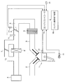
- FIG. 1 is a schematic configuration diagram of a control device for an internal combustion engine with a supercharger according to an embodiment of the present invention.
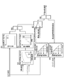
- FIG. 2 is a block diagram illustrating the function of the engine controller.
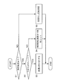
- FIG. 3 is a diagram illustrating a speed limit routine executed by the engine controller with a flowchart.
- the internal combustion engine 1 is an internal combustion engine for a vehicle, and burns a mixture of air and fuel to drive a piston. Air is sucked from the intake passage 5 through the intake manifold 3. Fuel is injected from an injector (not shown). Exhaust gas after combustion is discharged from the exhaust passage 2.
- an air cleaner 4 In the intake passage 5, an air cleaner 4, a supercharger 6, an intake throttle 8, and an intercooler 9 are provided.
- the supercharger 6 is provided with a bypass valve 7.
- the bypass valve 7 opens when the internal combustion engine 1 is at a high rotation speed and a low load, so that most of the air compressed by the supercharger 6 is returned to the upstream side of the compressor of the supercharger 6.
- the fact that the internal combustion engine 1 has a high rotation speed and a low load means that the supercharger 6 rotates at a high speed and the throttle opening of the intake throttle 8 is small.
- the bypass valve 7 is opened, most of the air compressed by the supercharger 6 is returned to the intake passage on the upstream side of the supercharger 6 in the intake passage 5.
- the intercooler 9 is located downstream of the intake throttle 8 in the intake passage 5. Therefore, the heat of the supercharged air at the outlet of the supercharger 6 is transmitted to the intake throttle 8 without being cooled by the intercooler 9. In such a case, it is necessary to lower the temperature of the supercharged air at the outlet of the supercharger 6 so that the intake throttle 8 is not overheated. For that purpose, it is necessary to reduce the recirculation amount of the supercharged air by the bypass valve 7.
- the supercharger 6 communicates with the internal combustion engine 1. For this reason, the recirculation amount of the supercharged air by the bypass valve 7 can be reduced by reducing the rotational speed of the internal combustion engine 1. Note that when the compressor of the supercharger 6 and the internal combustion engine 1 can be separated by a clutch, or when the intercooler 9 is provided between the compressor of the supercharger 6 and the intake throttle 8, the rotation of the internal combustion engine 1. There is no need to reduce the speed.
- the control device for an internal combustion engine with a supercharger includes an engine speed reduction device 16 that reduces the rotational speed of the internal combustion engine 1, and an engine controller 15 that controls the engine speed reduction device 16 based on the supercharged air temperature. .
- the engine controller 15 is constituted by a microcomputer and includes a CPU, that is, a central processing unit, a ROM, that is, a read-only memory, a RAM, that is, a random access memory, and an input / output interface. It is also possible to configure the engine controller 15 with a plurality of microcomputers.
- the engine controller 15 detects a supercharged air temperature at the outlet of the supercharger 6, a throttle opening sensor 17 that detects the opening of the intake throttle 8, and a rotational speed of the internal combustion engine 1. Detection data is respectively input from a crank angle sensor 18, an oil temperature sensor 19 that detects the cooling oil temperature of the internal combustion engine 1, and an inhibitor switch 20 that detects the position of a selector lever provided in the vehicle.
- the engine speed reduction device 16 can have various configurations.
- the engine speed reduction device 16 controls the continuously variable transmission to limit the rotational speed of the internal combustion engine 1.
- the rotational speed of the internal combustion engine 1 can be reduced without reducing the traveling speed of the vehicle by controlling the speed ratio of the continuously variable transmission in the decreasing direction.
- the engine speed reduction device 16 is configured to limit the rotational speed of the internal combustion engine 1 by controlling the stepped automatic transmission. be able to. In this case, the rotational speed of the internal combustion engine 1 can be reduced while the change in the traveling speed of the vehicle is suppressed as much as possible by shifting the transmission gear to the high speed side gear.
- the engine speed reduction device 16 may be configured to limit the rotation speed of the internal combustion engine 1 by cutting fuel supplied to the internal combustion engine 1. In this case, the rotational speed of the internal combustion engine 1 can be reliably reduced.
- the engine controller 15 can control the engine speed reduction device 16 so as to limit the rotational speed of the internal combustion engine 1 according to the supercharged air temperature.
- a limiting rotational speed that limits the rotational speed of the internal combustion engine 1 can be set stepwise in accordance with the supercharged air temperature. In this case, the influence of the rotational speed limitation on the driving performance of the vehicle can be suppressed as much as possible.
- the engine controller 15 further controls the engine speed so as to limit the rotational speed of the internal combustion engine 1 to a lower speed of the limited rotational speed based on the supercharged air temperature and the maximum allowable rotational speed for protecting the internal combustion engine 1.
- the lowering device 16 may be controlled. Thereby, damage prevention of the internal combustion engine 1 can be achieved reliably.
- the supercharged air temperature shows various rising modes according to the rotational speed and load of the internal combustion engine 1. For this reason, when the engine controller 15 is controlled by the engine controller 15 so as to limit the rotational speed of the internal combustion engine 1 according to the supercharged air temperature, the limited rotational speed is set according to the increase mode of the supercharged air temperature. It may be determined. In this case, it is possible to expand a region where the necessary torque of the internal combustion engine 1 can be secured.
- a decrease in the rotational speed of the internal combustion engine 1 causes a decrease in torque.
- the engine controller 15 and the engine speed reduction device 16 are set as follows. Can be configured. That is, when the engine speed reduction device 16 reduces the rotational speed of the internal combustion engine 1, the engine controller 15 can be configured to compensate for the shortage of torque of the internal combustion engine 1 by the electric motor. Therefore, the engine controller 15 and the engine speed reduction device 16 can be configured to compensate for the shortage of torque of the internal combustion engine 1 by the electric motor in a state where the rotational speed of the internal combustion engine 1 is limited. In this case, it is possible to eliminate the influence of the decrease in the rotational speed of the internal combustion engine 1 on the vehicle travel.
- the engine controller 15 and the engine speed reduction device 16 are configured as follows. can do.
- the engine controller 15 can be configured to disengage the clutch when the engine speed reducing device 16 reduces the rotational speed of the internal combustion engine 1. Therefore, the engine controller 15 and the engine speed reduction device 16 can be configured to disengage the clutch in a state where the rotational speed of the internal combustion engine 1 is limited. In this case, a favorable effect is brought about in suppressing torque shock.
- the engine speed reduction device 16 can be constituted by a microcomputer as with the engine controller 15.
- the engine controller 15 outputs a command to the engine speed reduction device 16 so as to limit the rotation speed of the internal combustion engine 1, or outputs information necessary for limiting the rotation speed of the internal combustion engine 1 to the engine speed reduction device 16. By doing so, the engine speed reduction device 16 can be controlled.
- the engine controller 15 and the engine speed reduction device 16 may be configured by one electronic control device.
- the engine controller 15 includes three types of component protection temperature region maps B1, B2, and B3.
- the component protection temperature region map B1 is a map set in consideration of the heat resistance of the components of the internal combustion engine 1.
- a region indicated by an asterisk in the drawing that is, a region where the intake air temperature is equal to or higher than a certain temperature is set as the component protection temperature region.
- an ON signal for the component protection temperature region map B1 is output.
- the component protection temperature region map B2 is set based on the rotational speed of the internal combustion engine 1 and the engine torque.
- the engine torque has the same meaning as the engine load.
- the accelerator opening of the vehicle and the throttle opening of the intake throttle 8 are used as parameters representing the engine torque.
- the throttle opening detected by the throttle opening sensor 17 is used as a parameter representing the engine torque.
- the component protection temperature region defined by the component protection temperature region map B2 is a high rotation and low load region indicated by an asterisk in the figure.
- the broken line in the figure indicates the maximum output torque of the internal combustion engine 1.
- the component protection temperature region map B3 is a map in which the duration time during which the internal combustion engine 1 is operated in the component protection temperature region defined by the component protection temperature region map B2 is set. In the component protection temperature region map B3, when the duration time exceeds a predetermined time as shown by the star in the figure, an ON signal for the component protection temperature region map B3 is output.
- Each signal for the component protection temperature region map B1 and the component protection temperature region map B3 is input to the AND circuit B6.
- the AND circuit B6 outputs a switching signal to the changeover switch B7 when both the signals for the component protection temperature region map B1 and the component protection temperature region map B3 are ON signals.
- the engine controller 15 further includes an engine high intake temperature limit speed map B4 and an engine high oil temperature limit speed map B5.
- the engine high intake air temperature limit speed map B4 is a map that defines the speed limit of the internal combustion engine 1 according to the intake air temperature detected by the temperature sensor 11. According to this map, the higher the intake air temperature, the lower the limit rotational speed is set.
- the high intake restriction speed which is the restriction speed set in the engine high intake temperature restriction speed map B4 according to the intake air temperature, is input to the changeover switch B7.
- the engine high oil temperature limited speed map B5 is a map that defines the limited rotational speed of the internal combustion engine 1 according to the engine oil temperature, which is the cooling oil temperature of the oil-cooled internal combustion engine 1.
- the engine oil temperature is detected by an oil temperature sensor 19. According to this map, the limit rotational speed is set to a lower value as the engine oil temperature is higher.
- the high oil temperature limited rotational speed that is the rotational speed limit set by the engine high oil temperature limited speed map B5 according to the engine oil temperature is output to the select low circuit B8.
- the limit rotation speed set by the engine high intake air temperature limit speed map B4 and the maximum rotation speed predetermined by the specifications of the internal combustion engine 1 are input to the changeover switch B7.
- the change-over switch B7 selects the high rotational speed limit rotational speed when the switching signal input from the AND circuit B6 is ON, and selects the maximum rotational speed when it is OFF and outputs it to the select low circuit B8.
- the select low circuit B8 selects the lower one of the high intake temperature limit rotation speed or the maximum rotation speed input from the changeover switch B7 and the high oil temperature limit rotation speed input from the engine high oil temperature limit speed map B5. Select and output as permissible rotational speed.
- the component protection temperature region maps B1, B2, and B3, the engine high intake air temperature limit speed map B4, and the engine high oil temperature limit speed map B5 are stored in advance in the ROM of the engine controller 15, respectively.
- the engine controller 15 limits the rotational speed of the internal combustion engine 1 by executing a speed limiting routine shown in FIG.
- the engine controller 15 determines in step S1 from the output of the select low circuit B8 whether the speed limit, that is, the rotational speed limit of the internal combustion engine 1 exists. Specifically, when the allowable rotational speed output from the select low circuit B8 is the maximum rotational speed, it is determined that there is no speed limit. When the allowable rotational speed output from the select low circuit B8 is a rotational speed limit set based on the engine high intake temperature limit speed map B4 or the engine high oil temperature limit speed map B5, it is determined that there is a limit. .
- step S1 determines whether the allowable rotational speed output from the select low circuit B8 is the maximum rotational speed. If the determination in step S1 is negative, that is, if the allowable rotational speed output from the select low circuit B8 is the maximum rotational speed, the engine controller 15 applies the unlimited rotational speed in step S5 and ends the routine. In other words, the routine is terminated without imposing a rotational speed limit on the internal combustion engine 1.
- step S1 determines in step S2 that the vehicle selector lever is in the D range or M range, Determine if it is in the drive range or manual range. This determination is made based on a signal from the inhibitor switch 20 that detects the selection range of the selector lever.
- the engine controller 15 decreases the gear ratio in step S3. Thereby, the rotational speed of the internal combustion engine 1 can be reduced without reducing the traveling speed of the vehicle.
- the transmission is an AT, that is, a stepped automatic transmission
- the engine controller 15 can perform an upshift in step S3 if the determination in step S2 is affirmative. Thereby, the influence which the fall of the rotational speed of the internal combustion engine 1 has on the traveling speed can be suppressed as much as possible.
- step S2 If the determination in step S2 is negative, the engine controller 15 reduces the rotational speed of the internal combustion engine 1 to the limit rotational speed by cutting the fuel to the internal combustion engine 1 in step S4.
- the processes in steps S3 and S4 are preferably feedback control.
- control device for the supercharged internal combustion engine includes the temperature sensor 11 that detects the supercharged air temperature of the internal combustion engine 1 and the internal combustion engine so that the supercharged air temperature does not exceed a predetermined temperature.
- the rotational speed of the supercharger 6 is reduced by limiting the rotational speed of the internal combustion engine 1, and the amount of supercharged air is reduced.
- the intake air temperature decreases. Therefore, the intake air temperature can be lowered with a simple configuration.
- the engine controller 15 and the engine speed reduction device 16 are configured so that the supercharged air temperature exceeds a predetermined temperature and the operating condition of the internal combustion engine 1 is in a predetermined high rotation / low load region. Limit the rotation speed. Thereby, the rotational speed of the internal combustion engine 1 can be limited only to the operation region of the internal combustion engine 1 where the supercharged air temperature is likely to rise. As a result, it is possible to suppress a decrease in the output torque and rotation speed of the internal combustion engine 1 as much as possible.
- the engine controller 15 and the engine speed reduction device 16 further have a predetermined state in which the supercharged air temperature exceeds a predetermined temperature and the operating condition of the internal combustion engine 1 is in a predetermined high rotation / low load region.
- the rotational speed of the internal combustion engine 1 is limited. According to such a configuration, since the rotational speed of the internal combustion engine 1 is limited after the state in which the internal combustion engine 1 is in the high rotation and low load region continues for a predetermined period, the rotational speed limitation of the internal combustion engine 1 is the driving performance of the vehicle. Can further suppress the influence on the.
- the engine controller 15 including an engine high intake air temperature limit speed map B4 that sets a limit rotation speed according to the intake air temperature, together with the engine speed reduction device 16, limits the rotation speed of the internal combustion engine 1 according to the supercharged air temperature. .
- the engine controller 15 including an engine high intake air temperature limit speed map B4 that sets a limit rotation speed according to the intake air temperature, together with the engine speed reduction device 16, limits the rotation speed of the internal combustion engine 1 according to the supercharged air temperature.
- the engine controller 15 limits the high intake air temperature at the changeover switch B7 when the rotational speed, load, and intake air temperature of the internal combustion engine 1 satisfy predetermined conditions based on the component protection temperature region maps B1, B2, and B3. Select the rotation speed.
- the engine controller 15 configured in this manner, together with the engine speed reduction device 16, limits the rotational speed of the internal combustion engine 1 to a high rotational speed at the time of high intake air temperature.
- the engine controller 15 and the engine speed reduction device 16 set the rotational speed of the internal combustion engine 1 to the high intake temperature limit rotational speed when the high intake temperature limit rotational speed is lower than the high oil temperature limit rotational speed. Restrict to. According to such a configuration, it is possible to accurately determine an opportunity that requires limiting the rotational speed of the internal combustion engine 1.
- the internal combustion engine 1 includes an intake throttle 8 downstream of the supercharger 6, an intercooler 9 downstream of the intake throttle 8, and a bypass valve 7. And under such a configuration, the supercharged air tends to overheat. Therefore, according to such a configuration, a particularly preferable effect can be obtained in reducing the intake air temperature of the internal combustion engine 1. According to such a configuration, by reducing the intake air temperature of the internal combustion engine 1, the supercharged air that recirculates upstream of the supercharger 6 via the bypass valve 7 among the supercharged air is reduced. Many can also be supplied to the internal combustion engine 1.
Landscapes
- Engineering & Computer Science (AREA)
- Chemical & Material Sciences (AREA)
- Combustion & Propulsion (AREA)
- Mechanical Engineering (AREA)
- General Engineering & Computer Science (AREA)
- Transportation (AREA)
- Automation & Control Theory (AREA)
- Output Control And Ontrol Of Special Type Engine (AREA)
- Control Of Vehicle Engines Or Engines For Specific Uses (AREA)
Abstract
過給機付き内燃機関の制御装置は、過給機を備える内燃機関の過給空気温度を検出する手段と、過給空気温度が所定温度を超えないように前記内燃機関の回転速度を制限する回転速度制限手段と、を備える。
Description
この発明は、過給機を備えた内燃機関の回転速度制御に関する。
過給機付きの内燃機関においては、過給空気の温度が上昇しやすい。過給空気温度の過度な上昇は内燃機関の運転性能や耐久性に影響を及ぼす。
過給空気温度の制御に関して、JP4-298636Aでは内燃機関の出力回転を変速機を介して過給機に入力し、変速機の変速比を変えることで過給空気温度を変化させることが開示されている。
JP7-26994Aでは、過給空気温度が許容限界温度に達すると、吸気弁の閉鎖タイミングを進角させることで過給空気温度が許容限界温度を超えて上昇しないようにすることが開示されている。
JP4-298636Aの技術は、過給機専用の変速機を必要とする。このため、部品数が多くなり、その分コストが高くなる。JP7-26994Aの技術は、可変動弁システムを必要とするうえ、可変動弁システムの応答速度は内燃機関の油温が高くなると低下する。そのため、過給空気温度の上昇が急な場合には、吸気弁の閉鎖タイミングが変わる前に、過給空気温度が許容範囲を超えてしまう可能性がある。
この発明は上記に鑑みてなされたものであり、簡易な構成による過給空気温度の制御を実現することを目的とする。
以上の目的を達成するために、この発明のある態様の過給機付き内燃機関の制御装置は、過給機を備える内燃機関の過給空気温度を検出する手段と、過給空気温度が所定温度を超えないように前記内燃機関の回転速度を制限する回転速度制限手段と、を備える。
以下、添付図面を参照しながら本発明の実施形態について説明する。
図1を参照しながら説明すると、内燃機関1は車両用の内燃機関であり、空気と燃料との混合気を燃焼させて、ピストンを駆動する。空気は吸気通路5から吸気マニホールド3を介して吸い込まれる。燃料は図示されないインジェクタから噴射される。燃焼後の排気は排気通路2から排出される。
吸気通路5にはエアクリーナ4、過給機6,吸気スロットル8、及びインタクーラ9が設けられる。過給機6にはバイパスバルブ7が併設される。
バイパスバルブ7は内燃機関1が高回転かつ低負荷の場合に開くことで、過給機6で圧縮された空気の大半を過給機6のコンプレッサ上流に還流する。ここで、内燃機関1が高回転かつ低負荷であることは、過給機6は高速回転し、吸気スロットル8のスロットル開度は小さいことを意味する。バイパスバルブ7が開くと、過給機6で圧縮された空気のほとんどが吸気通路5のうち過給機6の上流側の吸気通路に還流される。過給機6で圧縮されて温度上昇した過給空気が過給機6の上流に還流し、再び過給機6で圧縮されるというサイクルの繰り返しは、過給機6の出口の過給空気の温度を急上昇させる。
インタクーラ9は吸気通路5において吸気スロットル8より下流に位置する。そのため、過給機6の出口の過給空気の熱は、インタクーラ9で冷やされることなく、吸気スロットル8に伝達される。そして、このような場合には、吸気スロットル8が過熱状態とならないように、過給機6の出口の過給空気の温度を低下させる必要がある。そのためには、バイパスバルブ7による過給空気の還流量を減らす必要がある。
ここで、過給機6は内燃機関1に連通する。このため、内燃機関1の回転速度を低下させることで、バイパスバルブ7による過給空気の還流量を減らすことができる。なお、過給機6のコンプレッサと内燃機関1とをクラッチにより切り離し可能に構成する場合、または過給機6のコンプレッサと吸気スロットル8の間にインタクーラ9を設ける場合には、内燃機関1の回転速度を低下させる必要はない。
この実施形態にかかる過給機付き内燃機関の制御装置は、内燃機関1の回転速度を低下させるエンジン速度低下装置16と、過給空気温度に基づきエンジン速度低下装置16を制御するエンジンコントローラ15と、を備える。
エンジンコントローラ15はマイクロコンピュータで構成され、CPUすなわち中央演算装置と、ROMすなわち読み出し専用メモリと、RAMすなわちランダムアクセスメモリと、入出力インタフェースとを備える。エンジンコントローラ15を複数のマイクロコンピュータで構成することも可能である。
エンジンコントローラ15には、過給機6の出口の過給空気温度を検出する温度センサ11と、吸気スロットル8の開度を検出するスロットル開度センサ17と、内燃機関1の回転速度を検出するクランク角センサ18と、内燃機関1の冷却油温を検出する油温センサ19と、車両が備えるセレクタレバーの位置を検出するインヒビタスイッチ20と、から検出データがそれぞれ信号入力される。
次にエンジン速度低下装置16について説明する。エンジン速度低下装置16は様々な構成とすることが可能である。
内燃機関1が無段変速機(CVT)を介して車両を走行させる内燃機関である場合には、エンジン速度低下装置16は無段変速機を制御することで、内燃機関1の回転速度を制限するように構成することができる。この場合、無段変速機の変速比を減少方向に制御することで、車両の走行速度を低下させることなく内燃機関1の回転速度を低下させることができる。無段変速機の代わりに有段自動変速機を用いている車両においては、エンジン速度低下装置16は有段自動変速機を制御することで、内燃機関1の回転速度を制限するように構成することができる。この場合、変速ギアを高速側のギアにシフトすることで、車両の走行速度の変化を極力抑制しつつ内燃機関1の回転速度を低下させることができる。
エンジン速度低下装置16は内燃機関1に供給する燃料をカットすることで、内燃機関1の回転速度を制限するように構成されてもよい。この場合、内燃機関1の回転速度を確実に低下させることができる。
エンジンコントローラ15は、内燃機関1の回転速度を過給空気温度に応じて制限するようにエンジン速度低下装置16を制御することができる。エンジンコントローラ15でエンジン速度低下装置16をこのように制御するにあたっては、内燃機関1の回転速度を制限する制限回転速度を過給空気温度に応じて段階的に設定することができる。この場合、回転速度制限が車両の運転性能に及ぼす影響を極力抑えることができる。
エンジンコントローラ15はさらに、過給空気温度に基づく制限回転速度と、内燃機関1の保護のための最大許容回転速度とのうち低い方の速度に内燃機関1の回転速度を制限するようにエンジン速度低下装置16を制御してもよい。これにより、確実な内燃機関1の破損防止を図ることができる。
過給空気温度は、内燃機関1の回転速度や負荷に応じて様々な上昇態様を示す。このため、内燃機関1の回転速度を過給空気温度に応じて制限するようにエンジンコントローラ15でエンジン速度低下装置16を制御するにあたっては、制限回転速度を過給空気温度の上昇態様に応じて定めてもよい。この場合、必要な内燃機関1のトルクを確保できる領域を拡げることができる。
ところで、内燃機関1の回転速度の低下はトルクの低下をもたらす。これを補うために、内燃機関1が電動モータとの組み合わせにより車両を走行させるHEVすなわちハイブリッド駆動電気車両用の内燃機関である場合には、エンジンコントローラ15及びエンジン速度低下装置16を次のように構成することができる。すなわち、エンジン速度低下装置16が内燃機関1の回転速度を低下させる際に、エンジンコントローラ15が電動モータにより内燃機関1のトルクの不足分を補うように構成することができる。したがって、エンジンコントローラ15及びエンジン速度低下装置16は、内燃機関1の回転速度を制限している状態において、電動モータにより内燃機関1のトルクの不足分を補うように構成することができる。この場合、内燃機関1の回転速度の低下が車両走行に及ぼす影響をなくすことができる。
また、内燃機関1がHEV用の内燃機関であり、かつ内燃機関1のトルクを走行用動力としてクラッチを介して出力する場合には、エンジンコントローラ15及びエンジン速度低下装置16を次のように構成することができる。すなわち、エンジン速度低下装置16が内燃機関1の回転速度を低下させる際に、エンジンコントローラ15がクラッチを切断するように構成することもできる。したがって、エンジンコントローラ15及びエンジン速度低下装置16は、内燃機関1の回転速度を制限している状態において、クラッチを切断するように構成することもできる。この場合、トルクショックを抑制するうえで好ましい効果をもたらす。
エンジン速度低下装置16は、エンジンコントローラ15と同様にマイクロコンピュータで構成することができる。エンジンコントローラ15は、内燃機関1の回転速度を制限するようにエンジン速度低下装置16に指令を出力したり、内燃機関1の回転速度の制限に必要な情報をエンジン速度低下装置16に出力したりすることで、エンジン速度低下装置16を制御することができる。エンジンコントローラ15及びエンジン速度低下装置16は、一つの電子制御装置で構成されてもよい。
次に以上の制御を実現するためのエンジンコントローラ15の機能を説明する。
図2を参照して説明すると、エンジンコントローラ15は、3種類の部品保護温度領域マップB1,B2,B3を備える。部品保護温度領域マップB1は内燃機関1の構成部品の耐熱性を考慮して設定されるマップである。部品保護温度領域マップB1では、図中星印で示された領域、すなわち吸気温度が一定温度以上の領域が部品保護温度領域に設定される。部品保護温度領域マップB1において、温度センサ11の検出温度が部品保護温度領域にある場合、部品保護温度領域マップB1についてのON信号が出力される。
部品保護温度領域マップB2は、内燃機関1の回転速度とエンジントルクに基づき設定される。ここでエンジントルクはエンジン負荷と同じ意味であり、具体的には車両のアクセル開度や、吸気スロットル8のスロットル開度がエンジントルクを表すパラメータとして使用される。この実施形態では、エンジントルクを表すパラメータとしてスロットル開度センサ17が検出するスロットル開度を使用する。
内燃機関1の回転速度は車両が備えるクランク角センサ18から求められる。部品保護温度領域マップB2が規定する部品保護温度領域は図中星印に示される高回転低負荷の領域である。なお、図の破線は内燃機関1の最大出力トルクを示す。部品保護温度領域マップB3は部品保護温度領域マップB2が規定する部品保護温度領域で内燃機関1が運転される継続時間を設定したマップである。部品保護温度領域マップB3において当該継続時間が、図中星印に示されるように、所定時間を超えた場合、部品保護温度領域マップB3についてのON信号が出力される。
部品保護温度領域マップB1及び部品保護温度領域マップB3についての信号それぞれは、AND回路B6に入力される。AND回路B6は部品保護温度領域マップB1及び部品保護温度領域マップB3についての信号がともにON信号である場合に、切り替えスイッチB7に切り替え信号を出力する。
エンジンコントローラ15はさらに、エンジン高吸気温時制限速度マップB4とエンジン高油温時制限速度マップB5を備える。
エンジン高吸気温時制限速度マップB4は温度センサ11が検出した吸気温度に応じて内燃機関1の制限回転速度を規定するマップである。このマップによれば、吸気温度が高いほど制限回転速度は低い値に設定される。吸気温度に応じてエンジン高吸気温時制限速度マップB4が設定した制限回転速度である高吸気時制限回転速度は、切り替えスイッチB7に入力される。
エンジン高油温時制限速度マップB5は油冷式の内燃機関1の冷却油温度であるエンジン油温に応じて内燃機関1の制限回転速度を規定するマップである。エンジン油温は油温センサ19により検出される。このマップによれば、エンジン油温が高いほど制限回転速度は低い値に設定される。エンジン油温に応じてエンジン高油温時制限速度マップB5が設定した制限回転速度である高油温時制限回転速度は、セレクトロー回路B8に出力される。
切り替えスイッチB7には、エンジン高吸気温時制限速度マップB4が設定した制限回転速度と、内燃機関1の仕様により予め定められた最高回転速度とが入力される。切り替えスイッチB7はAND回路B6から入力される切り替え信号がONの場合には高吸気時制限回転速度を選択し、OFFの場合には最高回転速度を選択してセレクトロー回路B8に出力する。
セレクトロー回路B8は、切り替えスイッチB7から入力される高吸気時制限回転速度または最高回転速度と、エンジン高油温時制限速度マップB5から入力される高油温時制限回転速度のうち低い方を選択し、許容回転速度として出力する。
以上のうち、部品保護温度領域マップB1,B2,B3とエンジン高吸気温時制限速度マップB4とエンジン高油温時制限速度マップB5はそれぞれ、エンジンコントローラ15のROMに予め格納される。
さて、セレクトロー回路B8の出力に対して、エンジンコントローラ15は図3に示す速度制限ルーチンを実行することで内燃機関1の回転速度を制限する。
図3を参照しながら説明すると、エンジンコントローラ15はステップS1でセレクトロー回路B8の出力から速度制限、すなわち内燃機関1の回転速度制限が存在するかどうかを判定する。具体的には、セレクトロー回路B8から出力される許容回転速度が最高回転速度である場合には速度制限なしと判定する。セレクトロー回路B8から出力される許容回転速度が、エンジン高吸気温時制限速度マップB4またはエンジン高油温時制限速度マップB5に基づき設定された制限回転速度である場合には制限ありと判定する。
ステップS1の判定が否定的、すなわちセレクトロー回路B8から出力される許容回転速度が最高回転速度である場合には、エンジンコントローラ15はステップS5で制限なし回転速度を適用してルーチンを終了する。言い換えれば内燃機関1に回転速度制限を課すことなく、ルーチンを終了する。
ステップS1の判定が肯定的、すなわちセレクトロー回路B8から出力される許容回転速度が制限回転速度である場合には、エンジンコントローラ15はステップS2で、車両のセレクタレバーがDレンジまたはMレンジ、すなわちドライブレンジまたはマニュアルレンジにあるかどうかを判定する。この判定はセレクタレバーの選択レンジを検出するインヒビタスイッチ20からの信号に基づき行われる。
変速機がCVTすなわち無段変速機の場合には、ステップS2の判定が肯定的な場合に、エンジンコントローラ15はステップS3で変速比を小さくする。これにより、車両の走行速度を低下させずに内燃機関1の回転速度を低下させることができる。変速機がATすなわち有段自動変速機の場合には、ステップS2の判定が肯定的な場合に、エンジンコントローラ15はステップS3でシフトアップを行なうことができる。これにより内燃機関1の回転速度の低下が走行速度にもたらす影響を極力抑えることができる。
ステップS2の判定が否定的な場合には、エンジンコントローラ15はステップS4で内燃機関1への燃料カットにより内燃機関1の回転速度を制限回転速度へと低下させる。ステップS3とステップS4の処理はフィードバック制御とすることが望ましい。
以上のように、この実施形態による過給機付き内燃機関の制御装置は、内燃機関1の過給空気温度を検出する温度センサ11と、過給空気温度が所定温度を超えないように内燃機関1の回転速度を制限するエンジンコントローラ15及びエンジン速度低下装置16と、を備える。
この実施形態によれば、内燃機関1の回転速度を制限することで過給機6の回転速度が低下し、過給空気量が減少する。その結果、吸気温度が低下する。したがって、簡易な構成で吸気温度を低下させることができる。
この実施形態では、エンジンコントローラ15及びエンジン速度低下装置16は、過給空気温度が所定温度を超え、かつ内燃機関1の運転条件が所定の高回転低負荷領域にある場合に、内燃機関1の回転速度を制限する。これにより、過給空気温度が上がりやすい内燃機関1の運転領域に限って内燃機関1の回転速度を制限することができる。結果、内燃機関1の出力トルクや回転速度の低下を極力抑えることができる。
過給空気温度の上昇には時間遅れが伴う。このような事情に鑑み、エンジンコントローラ15及びエンジン速度低下装置16は、さらに、過給空気温度が所定温度を超え、かつ内燃機関1の運転条件が所定の高回転低負荷領域にある状態が所定期間継続した場合、すなわち一定時間継続した場合に、内燃機関1の回転速度を制限する。このような構成によれば、内燃機関1が高回転低負荷領域にある状態が所定期間継続してから内燃機関1の回転速度を制限するので、内燃機関1の回転速度制限が車両の運転性能に及ぼす影響をさらに抑えることができる。
吸気温度に応じて制限回転速度を設定するエンジン高吸気温時制限速度マップB4を備えるエンジンコントローラ15は、エンジン速度低下装置16とともに、内燃機関1の回転速度を過給空気温度に応じて制限する。このような構成によれば、例えば回転速度制限を段階的に行なうことで、回転速度制限が車両の運転に及ぼす影響を極力抑えることができる。
この実施形態では、エンジンコントローラ15は部品保護温度領域マップB1,B2,B3に基づき内燃機関1の回転速度、負荷、吸気温度が所定条件を満たした場合に、切り替えスイッチB7において高吸気温時制限回転速度を選択する。このように構成されたエンジンコントローラ15はエンジン速度低下装置16とともに、内燃機関1の回転速度を高吸気温時制限回転速度に制限する。エンジンコントローラ15及びエンジン速度低下装置16は具体的には、高吸気温時制限回転速度が高油温時制限回転速度よりも低い場合に、内燃機関1の回転速度を高吸気温時制限回転速度に制限する。このような構成によれば、内燃機関1の回転速度の制限を必要とする機会を的確に判定することができる。
この実施形態では、内燃機関1が、過給機6の下流に吸気スロットル8を、吸気スロットル8の下流にインタクーラ9を備えるとともに、バイパスバルブ7を備える。そして、このような構成のもとでは、過給空気が過熱しやすい。したがって、このような構成によれば、内燃機関1の吸気温度を低下させるうえで特に好ましい効果を得ることができる。このような構成によれば、内燃機関1の吸気温度を低下させることで、過給空気のうちバイパスバルブ7を介して過給機6の上流に還流する過給空気を減らし、過給空気の多くを内燃機関1に供給することもできる。
以上、本発明の実施形態について説明したが、上記実施形態は本発明の適用例の一部を示したに過ぎず、本発明の技術的範囲を上記実施形態の具体的構成に限定する趣旨ではない。
本願は2013年6月11日に日本国特許庁に出願された特願2013-122878に基づく優先権を主張し、この出願のすべての内容は参照により本明細書に組み込まれる。
Claims (12)
- 過給機を備える内燃機関の過給空気温度を検出する手段と、
過給空気温度が所定温度を超えないように前記内燃機関の回転速度を制限する回転速度制限手段と、を備える過給機付き内燃機関の制御装置。 - 請求項1に記載の過給機付き内燃機関の制御装置であって、
前記回転速度制限手段は、過給空気温度が所定温度を超え、かつ前記内燃機関の運転条件が所定の高回転低負荷領域にある場合に、前記内燃機関の回転速度を制限する過給機付き内燃機関の制御装置。 - 請求項2に記載の過給機付き内燃機関の制御装置であって、
前記回転速度制限手段は、過給空気温度が所定温度を超え、かつ前記内燃機関の運転条件が所定の高回転低負荷領域にある状態が一定時間継続した場合に、前記内燃機関の回転速度を制限する過給機付き内燃機関の制御装置。 - 請求項1から3いずれか1項に記載の過給機付き内燃機関の制御装置であって、
前記回転速度制限手段は、前記内燃機関の回転速度を過給空気温度に応じて制限する過給機付き内燃機関の制御装置。 - 請求項1から4いずれか1項に記載の過給機付き内燃機関の制御装置であって、
前記内燃機関は無段変速機を介して車両を走行させる内燃機関であり、
前記回転速度制限手段は前記無段変速機の変速比を制御することで前記内燃機関の回転速度を制限するよう構成される過給機付き内燃機関の制御装置。 - 請求項1から4いずれか1項に記載の過給機付き内燃機関の制御装置であって、
前記内燃機関は有段自動変速機を介して車両を走行させる内燃機関であり、
前記回転速度制限手段は前記有段自動変速機の変速段を制御することで前記内燃機関の回転速度を制限するよう構成される過給機付き内燃機関の制御装置。 - 請求項1から4いずれか1項に記載の過給機付き内燃機関の制御装置であって、
前記回転速度制限手段は前記内燃機関への燃料供給をカットすることで前記内燃機関の回転速度を制限するよう構成される過給機付き内燃機関の制御装置。 - 請求項1から7いずれか1項に記載の過給機付き内燃機関の制御装置であって、
前記内燃機関は電動モータとの組み合わせにより車両を走行させるハイブリッド駆動電気車両の内燃機関であり、
前記回転速度制限手段が前記内燃機関の回転速度を制限している状態において、前記電動モータにより前記内燃機関のトルクの不足を補うよう構成される過給機付き内燃機関の制御装置。 - 請求項1から8いずれか1項に記載の過給機付き内燃機関の制御装置であって、
前記内燃機関は電動モータとの組み合わせにより車両を走行させるハイブリッド駆動電気車両の内燃機関であり、
前記内燃機関のトルクが走行用動力としてクラッチを介して出力され、
前記回転速度制限手段が前記内燃機関の回転速度を制限している状態において、クラッチを切断するよう構成される過給機付き内燃機関の制御装置。 - 請求項1に記載の過給機付き内燃機関の制御装置であって、
前記回転速度制限手段は、前記内燃機関の回転速度、前記内燃機関の負荷、及び前記内燃機関の吸気温度が所定条件を満たした場合に、前記内燃機関の回転速度を制限するよう構成される過給機付き内燃機関の制御装置。 - 請求項1から10いずれか1項に記載の過給機付き内燃機関の制御装置であって、
前記内燃機関は、前記過給機の下流に吸気スロットルを、前記吸気スロットルの下流にインタクーラを備えるとともに、過給空気を吸気通路のうち前記過給機の上流側の吸気通路へ還流するバイパスバルブを備える過給機付き内燃機関の制御装置。 - 過給機を備える内燃機関の過給空気温度を検出し、過給空気温度が所定温度を超えないように前記内燃機関の回転速度を制限する過給機付き内燃機関の制御方法。
Applications Claiming Priority (2)
| Application Number | Priority Date | Filing Date | Title |
|---|---|---|---|
| JP2013122878 | 2013-06-11 | ||
| JP2013-122878 | 2013-06-11 |
Publications (1)
| Publication Number | Publication Date |
|---|---|
| WO2014199722A1 true WO2014199722A1 (ja) | 2014-12-18 |
Family
ID=52022024
Family Applications (1)
| Application Number | Title | Priority Date | Filing Date |
|---|---|---|---|
| PCT/JP2014/060863 Ceased WO2014199722A1 (ja) | 2013-06-11 | 2014-04-16 | 過給機付き内燃機関の制御装置及び過給機付き内燃機関の制御方法 |
Country Status (1)
| Country | Link |
|---|---|
| WO (1) | WO2014199722A1 (ja) |
Cited By (2)
| Publication number | Priority date | Publication date | Assignee | Title |
|---|---|---|---|---|
| US20180252314A1 (en) * | 2015-12-25 | 2018-09-06 | Kcm Corporation | Work vehicle |
| JP2020147195A (ja) * | 2019-03-14 | 2020-09-17 | トヨタ自動車株式会社 | ハイブリッド車両およびハイブリッド車両の制御方法 |
Citations (6)
| Publication number | Priority date | Publication date | Assignee | Title |
|---|---|---|---|---|
| JPS61252844A (ja) * | 1985-04-30 | 1986-11-10 | Mazda Motor Corp | 過給機付エンジンの制御装置 |
| JPS62237031A (ja) * | 1986-04-04 | 1987-10-17 | Mitsubishi Motors Corp | 過給機付きエンジンの制御装置 |
| JPS62240427A (ja) * | 1986-04-09 | 1987-10-21 | Mazda Motor Corp | 機械式過給機付エンジン |
| JPH04318236A (ja) * | 1991-04-16 | 1992-11-09 | Toyota Motor Corp | 過給機付内燃機関の自動変速制御装置 |
| JP2005069029A (ja) * | 2003-08-27 | 2005-03-17 | Toyota Motor Corp | 内燃機関の制御装置 |
| JP2005180362A (ja) * | 2003-12-22 | 2005-07-07 | Toyota Motor Corp | エンジンシステムの制御装置 |
-
2014
- 2014-04-16 WO PCT/JP2014/060863 patent/WO2014199722A1/ja not_active Ceased
Patent Citations (6)
| Publication number | Priority date | Publication date | Assignee | Title |
|---|---|---|---|---|
| JPS61252844A (ja) * | 1985-04-30 | 1986-11-10 | Mazda Motor Corp | 過給機付エンジンの制御装置 |
| JPS62237031A (ja) * | 1986-04-04 | 1987-10-17 | Mitsubishi Motors Corp | 過給機付きエンジンの制御装置 |
| JPS62240427A (ja) * | 1986-04-09 | 1987-10-21 | Mazda Motor Corp | 機械式過給機付エンジン |
| JPH04318236A (ja) * | 1991-04-16 | 1992-11-09 | Toyota Motor Corp | 過給機付内燃機関の自動変速制御装置 |
| JP2005069029A (ja) * | 2003-08-27 | 2005-03-17 | Toyota Motor Corp | 内燃機関の制御装置 |
| JP2005180362A (ja) * | 2003-12-22 | 2005-07-07 | Toyota Motor Corp | エンジンシステムの制御装置 |
Cited By (4)
| Publication number | Priority date | Publication date | Assignee | Title |
|---|---|---|---|---|
| US20180252314A1 (en) * | 2015-12-25 | 2018-09-06 | Kcm Corporation | Work vehicle |
| US11274745B2 (en) * | 2015-12-25 | 2022-03-15 | Hitachi Construction Machinery Co., Ltd. | Wheel loader |
| JP2020147195A (ja) * | 2019-03-14 | 2020-09-17 | トヨタ自動車株式会社 | ハイブリッド車両およびハイブリッド車両の制御方法 |
| JP7088088B2 (ja) | 2019-03-14 | 2022-06-21 | トヨタ自動車株式会社 | ハイブリッド車両およびハイブリッド車両の制御方法 |
Similar Documents
| Publication | Publication Date | Title |
|---|---|---|
| US11060466B2 (en) | System and method for controlling an electronically-controlled turbocharger | |
| JP5672417B2 (ja) | 内燃機関の制御装置及び制御方法 | |
| JP5293235B2 (ja) | エンジンの吸気制御方法及びその装置 | |
| JP6264329B2 (ja) | 車両用駆動制御装置 | |
| US10196065B2 (en) | Vehicle control system | |
| US20160252180A1 (en) | Shift control apparatus and shift control method | |
| US9644550B2 (en) | Control apparatus for vehicle | |
| JP2010163938A (ja) | 排気再循環装置 | |
| JP2008274846A (ja) | 排気温度低減制御装置及び方法 | |
| JP4784574B2 (ja) | 車両の制御装置、制御方法およびその方法をコンピュータに実現させるプログラムならびにそのプログラムを記録した記録媒体 | |
| JP2017008898A (ja) | 内燃機関の制御装置 | |
| JP2012144205A (ja) | ハイブリッド車両及び内燃機関の制御装置 | |
| JP6296430B2 (ja) | エンジンの制御装置 | |
| JP2008297946A (ja) | 内燃機関の制御装置 | |
| JP5994581B2 (ja) | 内燃機関の制御装置および制御方法 | |
| JP5760858B2 (ja) | 車両の制御装置 | |
| JP6010881B2 (ja) | 自動変速装置 | |
| JP6275179B2 (ja) | 内燃機関の制御装置 | |
| JP6108083B2 (ja) | 車両の制御装置 | |
| JP7026217B2 (ja) | 制御装置および制御方法 | |
| JP6030484B2 (ja) | 無段変速機の制御装置 | |
| JP2016151327A (ja) | 車両の制御装置 | |
| KR102053429B1 (ko) | 배기가스 재순환 장치 및 그 제어방법 | |
| JP2015229947A (ja) | 内燃機関の制御装置 | |
| JP2019078382A (ja) | 車両の制御装置及び車両の制御方法 |
Legal Events
| Date | Code | Title | Description |
|---|---|---|---|
| 121 | Ep: the epo has been informed by wipo that ep was designated in this application |
Ref document number: 14810593 Country of ref document: EP Kind code of ref document: A1 |
|
| NENP | Non-entry into the national phase |
Ref country code: DE |
|
| 122 | Ep: pct application non-entry in european phase |
Ref document number: 14810593 Country of ref document: EP Kind code of ref document: A1 |
|
| NENP | Non-entry into the national phase |
Ref country code: JP |