WO2014199665A1 - 断熱箱体 - Google Patents
断熱箱体 Download PDFInfo
- Publication number
- WO2014199665A1 WO2014199665A1 PCT/JP2014/054307 JP2014054307W WO2014199665A1 WO 2014199665 A1 WO2014199665 A1 WO 2014199665A1 JP 2014054307 W JP2014054307 W JP 2014054307W WO 2014199665 A1 WO2014199665 A1 WO 2014199665A1
- Authority
- WO
- WIPO (PCT)
- Prior art keywords
- box
- heat insulating
- groove
- gas vent
- insulating material
- Prior art date
- Legal status (The legal status is an assumption and is not a legal conclusion. Google has not performed a legal analysis and makes no representation as to the accuracy of the status listed.)
- Ceased
Links
Images





Classifications
-
- F—MECHANICAL ENGINEERING; LIGHTING; HEATING; WEAPONS; BLASTING
- F25—REFRIGERATION OR COOLING; COMBINED HEATING AND REFRIGERATION SYSTEMS; HEAT PUMP SYSTEMS; MANUFACTURE OR STORAGE OF ICE; LIQUEFACTION SOLIDIFICATION OF GASES
- F25D—REFRIGERATORS; COLD ROOMS; ICE-BOXES; COOLING OR FREEZING APPARATUS NOT OTHERWISE PROVIDED FOR
- F25D23/00—General constructional features
- F25D23/08—Parts formed wholly or mainly of plastics materials
-
- F—MECHANICAL ENGINEERING; LIGHTING; HEATING; WEAPONS; BLASTING
- F25—REFRIGERATION OR COOLING; COMBINED HEATING AND REFRIGERATION SYSTEMS; HEAT PUMP SYSTEMS; MANUFACTURE OR STORAGE OF ICE; LIQUEFACTION SOLIDIFICATION OF GASES
- F25D—REFRIGERATORS; COLD ROOMS; ICE-BOXES; COOLING OR FREEZING APPARATUS NOT OTHERWISE PROVIDED FOR
- F25D2201/00—Insulation
- F25D2201/10—Insulation with respect to heat
- F25D2201/12—Insulation with respect to heat using an insulating packing material
- F25D2201/126—Insulation with respect to heat using an insulating packing material of cellular type
Definitions
- the present invention relates to a heat insulating box having a gas vent hole in a foam heat insulating material.
- a heat insulating box used in a conventional refrigerator or the like is disclosed in Patent Document 1.
- the heat insulating box has an inner box having an opening on the front surface and an outer box covering the outside of the inner box, and a foamed heat insulating material such as polyurethane foam is filled between the inner box and the outer box.
- An inlet is provided on the bottom surface of the heat insulation box, and a plurality of gas vent holes are provided in the extending portion extending outward from the peripheral edge of the opening of the inner box.
- the stock solution of foam insulation is injected from the inlet, and the foam insulation is filled between the inner box and the outer box. At this time, the gas generated between the outer box and the inner box is exhausted from the gas vent hole. Thereby, generation
- the foam heat insulating material may leak from the gas vent hole, and there is a problem that the manufacturing cost increases in order to remove the leaked foam heat insulating material. Furthermore, since the appearance is impaired by the gas vent hole, it is necessary to provide a member that covers the gas vent hole, and there is a problem that the manufacturing cost of the heat insulation box increases.
- This invention aims at providing the heat insulation box which can aim at reduction of manufacturing cost by suppressing the fall of aesthetics.
- the present invention provides a heat insulating box body in which a foam heat insulating material is filled between an inner box having an opening on the front surface and an outer box covering the outer side of the inner box.
- An extension part extending outward from the periphery of the part, and a groove part recessed in the extension part, and the outer box has a front part covering the front surface of the groove part, and the foam is formed on the bottom surface of the groove part. It is characterized by providing a gas vent hole when the heat insulating material is foamed.
- the present invention includes a protrusion protruding rearward on the bottom surface of the groove and a holding portion bent continuously in a U shape on the front portion, and the holding portion is The front surface of the extended portion and the protrusion are sandwiched by elasticity.
- the present invention further includes a partition part that partitions the interior of the inner box in the vertical direction to form a plurality of sections, and communicates with the groove and extends inward from the inner edge of the front part.
- the communication path is provided on the partition part or on the extension part adjacent to the partition part.
- the present invention is characterized in that, in the heat insulating box having the above-described configuration, an inlet for injecting the foam heat insulating material is provided on an upper surface or a bottom surface of the heat insulating box.
- the outer box has a front surface portion that covers the front surface of the groove portion, and a gas vent hole is provided on the bottom surface of the groove portion, even if the foam insulation is leaked from the gas vent hole, it is retained in the groove portion to prevent poor appearance. can do. Thereby, the fall of aesthetics can be suppressed and the manufacturing cost can be reduced.
- FIG. 1st Embodiment of this invention Side surface sectional drawing which shows the refrigerator of 1st Embodiment of this invention.
- the front view which expanded the X section of FIG. The front view which shows the communicating path of the heat insulation box of the refrigerator of 2nd Embodiment of this invention Side surface sectional drawing which shows the refrigerator of 3rd Embodiment of this invention.
- FIG. E The perspective view which shows the heat insulation box of the refrigerator of 3rd Embodiment of this invention.
- Sectional view cut along line CC in FIG. F arrow view of FIG. The rear view which shows the heat insulation box of the refrigerator of 3rd Embodiment of this invention.
- FIG. 1 is a side sectional view showing the refrigerator 1 of the first embodiment.
- the refrigerator 1 has a heat insulating box 2 filled with a foam heat insulating material 23 such as polyurethane foam between the outer box 8 and the inner box 9.
- the heat insulation box 2 is provided with a refrigerator compartment 3, a freezer compartment 4, and a vegetable compartment 5 in order from the top.
- the refrigerator compartment 3 and the freezer compartment 4 are partitioned by a partition 6 that is separately formed and assembled in the inner box 9, and the freezer compartment 4 and the vegetable compartment 5 are partitioned by a partition 7 that is separately formed and assembled in the inner box 9. It is done.
- the partition parts 6 and 7 are filled with a foam heat insulating material 23.
- the refrigerator compartment 3 stores stored items in a refrigerated state, and the opening 3a on the front surface is opened and closed by a pivotable door 3b.
- the freezer 4 stores stored items in a frozen state, and the opening 4a on the front surface is opened and closed by a drawer-type door 4b formed integrally with a storage case 12 for storing the stored items.
- the vegetable room 5 refrigerates stored items at a refrigeration temperature higher than that of the refrigerated room 3, and stores vegetables and fruits.
- the front opening 5a of the vegetable compartment 5 is opened and closed by a drawer-type door 5b formed integrally with the storage case 10.
- a machine room 16 is provided on the back side of the vegetable room 5.
- the machine room 16 is provided with a compressor 17 that operates the refrigeration cycle.
- the rear surface of the machine room 16 is closed by a machine room cover (not shown).
- a cold air passage 21 through which cold air flows is provided behind the freezer compartment 4.
- a discharge port 21 a and a return port 21 b that face the freezer compartment 4 are opened in the cold air passage 21.
- a cooler 15 serving as a low temperature part of the refrigeration cycle is disposed in the cold air passage 21.
- a blower fan 14 is disposed above the cooler 15.
- a cold air passage 22 communicating with the cold air passage 21 via a damper (not shown) is provided behind the refrigerator compartment 3.
- a discharge port 22 a facing the inside of the refrigerator compartment 3 is opened in the cold air passage 22.
- a conduction path (not shown) that leads to the vegetable compartment 5 is led out in the refrigerator compartment 3, and the cold air that has flowed out of the refrigerator compartment 3 is discharged to the vegetable compartment 5 through the conduction passage.
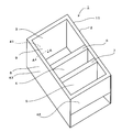
- FIG. 2 shows a perspective view of the heat insulation box 2 as viewed from the front.
- the inner box 9 is formed of a resin molded product
- the outer box 8 is formed of a steel plate.
- the outer box 8 is arranged on the outer side of the inner box 9 with a predetermined distance from the inner box 9, and a foam heat insulating material 23 is filled therebetween.
- the outer box 8 is configured by connecting a top plate 41, side plates 43 and 44 (see FIG. 4), a back plate 40 (see FIG. 3), and a bottom plate.
- the top plate 41, the side plates 43 and 44, the back plate 40, and the bottom plate 42 form the top surface, both side surfaces, the back surface, and the bottom surface of the heat insulating box 2, respectively.
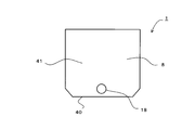
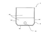
- FIG. 3 and 4 show a top view and a bottom view of the heat insulation box 2.
- the top plate 41 and the bottom plate 42 are respectively provided with inlets 18 and 19 through which a stock solution of the foam heat insulating material 23 is injected.
- a plurality of inlets 18 and 19 may be provided on the top plate 41 and the bottom plate 42, respectively.
- the heat insulating box 2 is arranged with the back plate 40 facing downward, and the stock solution of the foam heat insulating material 23 is injected from the injection ports 18 and 19.
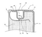
- FIG. 5 shows a bottom cross-sectional view taken along line AA in FIG.
- the inner box 9 has an extending portion 28 extending outward from the peripheral edge 27 of the opening 3a (the same applies to the openings 4a and 5a).
- a groove 29 is recessed in the center of the extended portion 28, and a front surface 35 that covers the groove 29 is provided in the outer box 8.
- FIG. 6 shows a perspective view of the heat insulation box 2 with the front face 35 omitted.
- the groove 29 is formed in an annular shape along the peripheral wall of the heat insulating box 2.
- a gas vent hole 30 is opened on the bottom surface 29 a of the groove 29, and a protrusion 31 is provided on the back side of the groove 29.
- the gas vent hole 30 is disposed on the inner side (inner box 9 side) than the protruding portion 31 and is formed to have a size (for example, a diameter of 1 mm) such that the foam heat insulating material 23 does not leak. Thereby, the gas generated when the foam heat insulating material 23 is filled is exhausted from the gas vent hole 30 into the groove 29 as indicated by an arrow D1.
- the front part 35 is formed by bending the front end of the outer box 8 made of a metal plate inward.
- the outer box 8 is formed with a holding portion 36 that is continuous with the front surface portion 35.
- the holding portion 36 is formed by folding a metal plate forming the outer box 8 at the inner edge of the front portion 35 and further bending it in a U shape outside the extending portion 28.
- the holding portion 36 is formed in a U shape, the front surface 28a of the extending portion 28 and the protruding portion 31 are elastically sandwiched. As a result, the inner box 9 is held by the outer box 8, and the foam heat insulating material 23 is filled up to the inner surface side of the protruding portion 31.
- FIG. 7 shows an enlarged front view of a portion X in FIG.
- the extending portion 28 of the inner box 9 is provided with a communication passage 9b adjacent to the left and right ends of the partition portion 6 for communicating the openings 3a, 4a and the groove portion 29, respectively.
- the communication path 9 b is provided adjacent to the left and right end portions of the partition portion 7.
- the front surface of the communication path 9 b is covered with the front surface portion 35.
- the front surface of the communication passage 9b inside the front surface portion 35 is exposed, but the communication passage 9b is adjacent to the partition portions 6 and 7, so that it is not noticeable, and the deterioration of the aesthetic appearance of the heat insulating box 2 can be suppressed.
- the gas filled in the groove 29 is exhausted into the openings 3a and 4a as shown by arrows D2 and D3 through the communication passage 9b.
- the foam heat insulating material 23 leaked from the gas vent hole 30 is held in the groove 29. Can do. Moreover, since the groove part 29 is covered with the front part 35 provided in the outer box 8, the leakage of the foam heat insulating material 23 is prevented. Therefore, it is not necessary to separately provide a cover for covering the gas vent hole 30, and the removal of the leaked foam heat insulating material 23 can be made unnecessary. Therefore, the cost of the heat insulation box 2 can be reduced.
- the holding portion 36 sandwiches the front surface 28a of the extending portion 28 and the projection portion 31 by elasticity, the inner box 9 can be easily held by the outer box 8.
- the communication passage 9b is provided adjacent to the partition portions 6 and 7 that form a plurality of sections by dividing the inside of the inner box 9 in the vertical direction, the foam insulation 23 can be easily filled through the communication passage 9b. Gas can be exhausted, and the communication passage 9b can be made inconspicuous, so that the appearance of the heat insulating box 2 can be prevented from being deteriorated.
- the inlets 18 and 19 into which the foam heat insulating material 23 is injected are provided in the upper surface plate 41 (upper surface) or the bottom surface plate 42 (bottom surface) of the heat insulating box 2, the inlets 18 and 19 are located at positions where it is difficult to see from the user.
- the appearance quality of the heat insulation box 2 can be improved.
- FIG. 8 is a front view of the right end portion of the partition portion 6 and the groove portion 29 (portion corresponding to the portion X in FIG. 6) of the heat insulation box 2 of the present embodiment.
- the same parts as those in the first embodiment are denoted by the same reference numerals.
- a communication path 37 that communicates with the groove 29 and extends inward from the inner edge of the front surface 35 is provided on the front surface of the partition 6. Further, a cover (not shown) that covers the front surface is provided on the front surface of the partition portion 6 at a predetermined distance from the partition portion 6. Thereby, gas is discharged in the directions of arrows D4 and D5 when foaming heat insulating material 23 is foamed through communication passage 37.
- the communication path 37 is similarly provided at the left end portion of the partition part 6, and the communication path 37 is also provided at the left and right end parts of the partition part 7. In addition, you may provide the communication path 37 in the upper and lower surfaces of the partition parts 6 and 7. FIG.
- the partition portion 6 is provided with the communication passage 37 on the partition portion 6 that communicates with the groove portion 29 and extends inward from the inner edge of the front surface portion 35, the foam heat insulating material is provided via the communication passage 37.
- the gas can be easily exhausted, and the communication passage 37 is made inconspicuous so that a decrease in the appearance of the heat insulating box 2 can be suppressed.
- the refrigerator 1 of 3rd Embodiment is demonstrated.
- the present embodiment is different from the first embodiment in the structure of the back surface portion 39 of the heat insulating box 2, and the other portions are the same as those in the first embodiment.
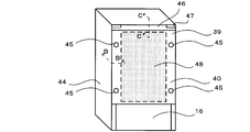
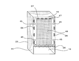
- 9 and 10 are side sectional views showing the heat insulation box 2 of the present embodiment, and perspective views seen from the back.
- the same parts as those in the first embodiment are denoted by the same reference numerals.
- a vacuum heat insulating material 48 is provided between the outer box 8 and the inner box 9 on the back surface 39 of the heat insulating box 2.
- the vacuum heat insulating material 48 is formed in a substantially rectangular shape having a uniform thickness, and the upper end extends to the vicinity of the upper surface plate 41 and the lower end extends to the vicinity of the machine room 16.
- the inlet 45 is provided in the back plate 40 provided in the back part 39.
- Four inlets 45 are provided at positions that do not overlap with the vacuum heat insulating material 48 when rear projected, and the stock solution of the foam heat insulating material 23 is injected from the respective injection ports 45.
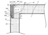
- FIG. 11 is a bottom cross-sectional view taken along the line BB in FIG. 10, and FIG. 12 is a view taken along arrow E in FIG.
- the side plate 44 is formed with a groove 44a extending in the vertical direction by bending the rear end into an S-shape.
- gas vent holes 44b are arranged in parallel in a vertical direction with a cycle y1 (about 100 to 200 mm) and a predetermined size (about 1 to 1.5 mm in diameter).
- the U-shaped portion 44d at the end of the side wall 44c abuts on the back plate 40 and is formed in a U-shape.
- the back plate 40 has a bent portion 40a that bends both side ends forward, and the bent portion 40a is inserted into the groove 44a.
- the bent portion 40a is provided with a protrusion 40b and a gas vent hole 40c in order from the back.
- the protrusions 40b have a diameter of about 0.5 to 1.0 mm and are arranged in parallel in the vertical direction with a period y3 (about 50 to 100 mm).
- the gas vent holes 40c have a predetermined diameter (about 1 to 1.5 mm) and are arranged in parallel in the vertical direction with a cycle y2 (about 100 to 200 mm).
- the side-by-side direction (up-down direction) in which the gas vent holes 44b of the side plate 44 are arranged is the same direction as the side-by-side direction in which the gas vent holes 40c are arranged. About 100 mm).
- the distance y0 from the center of the gas vent holes 40c, 44b to the bottom of the groove 44a is about 1/3 of the depth of the groove 44a. Further, the opposing side plates 44 are formed in the same manner.
- FIG. 13 shows a side cross-sectional view taken along the line CC in FIG. 10, and FIG. 14 shows a view taken in the direction of arrow F in FIG.
- a handle member 46 is provided at the rear end of the upper surface plate 41.
- the handle member 46 has a handle 47 and a groove 46a.
- the handle 47 is recessed at the left and right ends of the back surface of the handle member 46. Thereby, the handle 47 can be gripped when the user moves the heat insulating box 2.
- the groove part 46a is formed by opening the lower part, and the upper end part 40f of the back plate 40 is inserted into the groove part 46a.
- the upper end portion 40f is provided with a V-shaped portion 40d, and the tip end portion of the V-shaped portion 40d is in contact with the side wall 46b of the groove portion 46a.
- a gas vent hole 40h is provided in parallel with a predetermined diameter (about 1 to 1.5 mm) and a cycle y4 (about 50 to 100 mm) in the left-right direction.
- a predetermined gap is formed between the back side wall 46 c of the groove 46 a and the back plate 40.
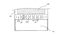
- FIG. 15 is a plan view showing a lower end portion of the back plate 40.
- a large number of gas vent holes 40k (diameter 1 to 1.5 mm) are provided at the lower end of the back plate 40.
- the first pattern formed by the five gas vent holes 40k is repeated in the left-right direction at a predetermined cycle y5 (for example, about 40 to 50 mm).
- the second pattern composed of the gas vent holes 40k having a smaller quantity than the first pattern is repeated at the cycle y5.
- the density of the gas vent hole 40k in the central portion in the left-right direction is larger than that at both ends.
- the gas vent hole 40k is covered with a cover (not shown) of the machine room 16. Further, the interval y6 between the upper gas vent hole 40k and the lower gas vent hole 40k of each pattern is formed to be about 15 to 20 mm.
- the heat insulation box 2 configured as described above, the heat insulation box 2 is arranged with the back plate 40 facing upward, and the stock solution of the foam heat insulating material 23 is injected from each inlet 45. At this time, when the foam heat insulating material 23 is filled between the inner box 9 and the outer box 8 and foams, gas is generated. At this time, the gas is discharged at the rear end of the side plate 44 from the passage 49 as shown by an arrow D6 through the gas vent holes 44b and 40c as shown in FIGS.
- the gas is discharged from the passage 50 at the upper end portion 40f of the back plate 40 through the gas vent hole 40h as shown by an arrow D7.
- the filling of the foam heat insulating material 23 is completed near the lower end of the back plate 40. For this reason, by providing a large number of gas vent holes 40k in the vicinity of the lower end of the back plate 40, the gas during filling can be reliably discharged as shown by the arrow D8.
- the side plate 44 has the bent portions 40a bent at both ends of the back plate 40 inserted in the groove portion 44a formed by bending the rear end.
- the gas vent hole 44b is provided in the side wall 44c of the groove part 44a, and the gas vent hole 40c is provided in the bending part 40a.
- the gas vent hole 44b and the gas vent hole 40c are arranged at positions where they do not overlap in the side projection. For this reason, the foam heat insulating material 23 exposed from the gas vent hole 44 b is held between the side wall 44 c and the bent portion 40 a, and exposure to the outside through the passage 49 is prevented.
- a gas vent hole 40h is provided in the upper end portion 40f of the back plate 40 inserted into the groove portion 46a provided in the handle member 46. For this reason, since the gas vent hole 40h is not exposed, it is not necessary to separately provide a member for covering them, and it is possible to reduce the cost of the heat insulation box 2 and the refrigerator 1 by preventing a decrease in aesthetic appearance.
- the gas vent hole 40k provided at the lower end of the back plate 40 is covered with a cover (not shown) of the machine chamber 16. For this reason, since the gas vent hole 40k is not exposed, it is not necessary to separately provide a member for covering them, and the cost of the heat insulating box 2 and the refrigerator 1 can be reduced by preventing a decrease in aesthetic appearance.
- the present invention can be used for a heat insulating box having a gas vent hole of a foam heat insulating material.
Landscapes
- Engineering & Computer Science (AREA)
- Chemical & Material Sciences (AREA)
- Combustion & Propulsion (AREA)
- Physics & Mathematics (AREA)
- Mechanical Engineering (AREA)
- Thermal Sciences (AREA)
- General Engineering & Computer Science (AREA)
- Refrigerator Housings (AREA)
Abstract
本発明は美観の低下を抑制して製造コストの削減を図ることのできる断熱箱体を提供する。前面に開口部3a、4a、5aを有する内箱9と、内箱9の外側を覆う外箱8と、の間に発泡断熱材23を充填した断熱箱体2を備えた断熱箱体2において、内箱9が開口部3a、4a、5aの周縁27から外側に延びる延設部28と、延設部28に凹設される溝部29とを有するとともに、外箱8が溝部29の前面を覆う前面部35を有し、溝部29の底面29aに発泡断熱材23の発泡時のガス抜孔30を設けた。
Description
本発明は発泡断熱材のガス抜孔を有する断熱箱体に関する。
従来の冷蔵庫等で使用される断熱箱体は特許文献1に開示されている。断熱箱体は前面に開口部を有する内箱と、内箱の外側を覆う外箱とを有し、内箱と外箱との間にはポリウレタンフォーム等の発泡断熱材が充填される。
断熱箱体の底面には注入口が設けられ、内箱の開口部の周縁から外側に延びる延設部には複数のガス抜孔が設けられる。
注入口からは発泡断熱材の原液が注入され、内箱と外箱との間に発泡断熱材が充填される。この時、外箱と内箱との間に発生するガスはガス抜孔から排気される。これにより、ボイドの発生を抑制して発泡断熱材を充填することができる。
上記従来の断熱箱体によると、発泡断熱材がガス抜孔から漏出する場合があり、漏出した発泡断熱材を除去するために製造コストが増加するという問題がある。さらに、ガス抜孔により美観が損なわれるため、ガス抜孔を覆う部材を設ける必要があり、断熱箱体の製造コストが増加するという問題もある。
本発明は、美観の低下を抑制して製造コストの削減を図ることのできる断熱箱体を提供することを目的とする。
上記目的を達成するために本発明は、前面に開口部を有する内箱と前記内箱の外側を覆う外箱との間に発泡断熱材を充填した断熱箱体において、前記内箱が前記開口部の周縁から外側に延びる延設部と、前記延設部に凹設される溝部とを有するとともに、前記外箱が前記溝部の前面を覆う前面部を有し、前記溝部の底面に前記発泡断熱材の発泡時のガス抜孔を設けたことを特徴とする。
また本発明は、上記構成の断熱箱体において、前記溝部の底面に後方に突出する突起部と、前記前面部に連続してU字状に屈曲する保持部と、を設け、前記保持部は前記延設部の前面と前記突起部との間を弾性により挟持することを特徴とする。
また本発明は、上記構成の断熱箱体において、前記内箱内を上下方向に仕切って複数の区画を形成する仕切部を備え、前記溝部に連通して前記前面部の内縁よりも内側に延びる連通路を前記仕切部上又は前記仕切部に隣接して前記延設部上に設けたことを特徴とする。
また本発明は、上記構成の断熱箱体において、前記断熱箱体の上面又は底面に前記発泡断熱材が注入される注入口が設けられることを特徴とする。
本発明によると、外箱が溝部の前面を覆う前面部を有し、溝部の底面にガス抜孔を設けたため、ガス抜孔から発泡断熱材が漏出した場合も溝部内に保持されて外観不良を防止することができる。これにより、美観の低下を抑制して製造コストの削減を図ることができる。
<第1実施形態>
以下に本発明の実施形態を図面を参照して説明する。図1は第1実施形態の冷蔵庫1を示す側面断面図である。冷蔵庫1は外箱8と内箱9との間にポリウレタンフォーム等の発泡断熱材23を充填した断熱箱体2を有している。
以下に本発明の実施形態を図面を参照して説明する。図1は第1実施形態の冷蔵庫1を示す側面断面図である。冷蔵庫1は外箱8と内箱9との間にポリウレタンフォーム等の発泡断熱材23を充填した断熱箱体2を有している。
断熱箱体2には上方から順に冷蔵室3、冷凍室4、野菜室5が設けられる。冷蔵室3と冷凍室4とは内箱9に予め別に形成され組み付けられる仕切部6によって仕切られ、冷凍室4と野菜室5とは内箱9に予め別に形成され組み付けられる仕切部7によって仕切られる。仕切部6、7内には発泡断熱材23が充填される。
冷蔵室3は貯蔵物を冷蔵保存し、前面の開口部3aは回動式の扉3bにより開閉される。冷凍室4は貯蔵物を冷凍保存し、前面の開口部4aは貯蔵物を収納する収納ケース12と一体に形成された引き出し式の扉4bにより開閉される。
野菜室5は貯蔵物を冷蔵室3よりも高温の冷蔵温度で冷蔵保存し、野菜や果物などを収納する。野菜室5の前面の開口部5aは収納ケース10と一体に形成された引き出し式の扉5bにより開閉される。
野菜室5の背面側には機械室16が設けられる。機械室16には冷凍サイクルを運転する圧縮機17が配される。機械室16の背面は機械室カバー(不図示)により塞がれる。
冷凍室4の背後には冷気が流通する冷気通路21が設けられる。冷気通路21には冷凍室4内に臨む吐出口21a及び戻り口21bが開口する。冷気通路21には冷凍サイクルの低温部となる冷却器15が配される。冷却器15の上方には送風ファン14が配される。
冷蔵室3の背後にはダンパ(不図示)を介して冷気通路21に連通する冷気通路22が設けられる。冷気通路22には冷蔵室3内に臨む吐出口22aが開口する。冷蔵室3には野菜室5に導通する導通路(不図示)が導出され、冷蔵室3から流出した冷気は導通路を介して野菜室5に吐出される。
図2は断熱箱体2の前方から見た斜視図を示している。内箱9は樹脂成形品により形成され、外箱8は鋼板により形成される。外箱8は内箱9に対して所定量隔てて内箱9の外側に配され、両者間に発泡断熱材23が充填される。
外箱8は上面板41、側面板43、44(図4参照)、背面板40(図3参照)及び底面板42を連結して構成される。上面板41、側面板43、44、背面板40及び底面板42は、それぞれ断熱箱体2の上面、両側面、背面及び底面を形成する。
図3、図4は断熱箱体2の上面図及び底面図を示している。上面板41及び底面板42には発泡断熱材23の原液が注入される注入口18、19がそれぞれ設けられる。断熱箱体2が大型の場合には、上面板41及び底面板42にそれぞれ複数の注入口18、19を設けてもよい。尚、断熱箱体2は背面板40を下方に面して配置して、注入口18、19から発泡断熱材23の原液が注入される。
図5は図2のA-A線で切断した底面断面図を示している。内箱9は開口部3a(開口部4a、5aも同様)の周縁27から外側に延びる延設部28を有している。延設部28の中央には溝部29が凹設され、外箱8には溝部29を覆う前面部35が設けられる。
図6は前面部35を省いた断熱箱体2の斜視図を示している。図5、図6において、溝部29は断熱箱体2の周壁に沿って環状に形成される。溝部29の底面29aにはガス抜孔30が開口し、溝部29の背面側には突起部31が突設される。
ガス抜孔30は突起部31よりも内側(内箱9側)に配され、発泡断熱材23が漏出しない程度の大きさ(例えば直径1mm)に形成される。これにより、発泡断熱材23が充填された際に発生するガスが矢印D1に示すようにガス抜孔30から溝部29内に排気される。
この時、ガス抜孔30から発泡断熱材23が漏出しても溝部29内に保持されるとともに溝部29が前面部35により覆われる。このため、漏出した発泡断熱材23を除去する必要がない。
前面部35は金属板から成る外箱8の前端を内側に折曲して形成される。また、外箱8には前面部35に連続する保持部36が形成される。保持部36は外箱8を形成する金属板を前面部35の内縁で折り返して延設部28の外側で更にU字状に屈曲して形成される。
保持部36はU字状に形成されるため、延設部28の前面28aと突起部31とを弾性により挟持する。これにより、外箱8により内箱9が保持され、発泡断熱材23は突起部31の内面側まで充填される。
図7は図6のX部を拡大した正面図を示している。内箱9の延設部28には仕切部6の左右の端部に隣接して開口部3a、4aと溝部29とをそれぞれ連通させる連通路9bが設けられる。また、連通路9bは仕切部7の左右の端部にも隣接して設けられる。連通路9bの前面は前面部35により覆われる。
この時、前面部35より内側の連通路9bの前面が露出するが、連通路9bが仕切部6、7に隣接するため目立たなく、断熱箱体2の美観の低下を抑制することができる。また、溝部29内に充填したガスは連通路9bを介して矢印D2、D3に示すように開口部3a、4a内に排気される。
本実施形態によると、内箱8の延設部28に凹設した溝部29の底面29aにガス抜孔30を設けたので、ガス抜孔30から漏出した発泡断熱材23を溝部29内に保持することができる。また、外箱8に設けた前面部35によって溝部29が覆われるため、発泡断熱材23の漏出が防止される。従って、ガス抜孔30を覆うカバーを別途設ける必要がなく、漏出した発泡断熱材23の除去を不要にできる。従って、断熱箱体2のコストを削減することができる。
また、保持部36は延設部28の前面28aと突起部31との間を弾性により挟持するため、外箱8により内箱9を容易に保持することができる。
また、内箱9内を上下方向に仕切って複数の区画を形成する仕切部6、7に隣接して連通路9bを設けたため、連通路9bを介して容易に発泡断熱材23の充填時のガスを排気することができるとともに、連通路9bを目立たなくして断熱箱体2の美観低下を抑制することができる。
また、断熱箱体2の上面板41(上面)又は底面板42(底面)に発泡断熱材23が注入される注入口18、19が設けられるため、ユーザから見えにくい位置に注入口18、19を配して断熱箱体2の外観品質を向上できる。
<第2実施形態>
次に、第2実施形態の冷蔵庫1について説明する。本実施形態は第1実施形態の連通路9b(図7参照)に替えて連通路37が設けられる。その他の部分は第1実施形態と同様である。図8は本実施形態の断熱箱体2の仕切部6の右の端部及び溝部29の正面図(図6のX部に相当する部分)である。説明の便宜上、第1実施形態と同様の部分には同一の符号を付している。
次に、第2実施形態の冷蔵庫1について説明する。本実施形態は第1実施形態の連通路9b(図7参照)に替えて連通路37が設けられる。その他の部分は第1実施形態と同様である。図8は本実施形態の断熱箱体2の仕切部6の右の端部及び溝部29の正面図(図6のX部に相当する部分)である。説明の便宜上、第1実施形態と同様の部分には同一の符号を付している。
仕切部6の前面には溝部29に連通して前面部35の内縁よりも内側に延びる連通路37が設けられている。また、仕切部6の前面には前面を覆うカバー(不図示)が仕切部6と所定距離だけ離れて設けられる。これにより、連通路37を介して発泡断熱材23の発泡時にはガスが矢印D4、D5の方向に排出される。
また、仕切部6の左端部にも同様に連通路37が設けられとともに、仕切部7の左右の端部にも連通路37が設けられる。尚、連通路37を仕切部6、7の上下面に設けてもよい。
本実施形態によると、仕切部6には溝部29に連通して前面部35の内縁よりも内側に延びる連通路37を仕切部6上に設けているため、連通路37を介して発泡断熱材23の発泡時にはガスを容易に排気することができるとともに、連通路37を目立たなくして断熱箱体2の美観低下を抑制することができる。
<第3実施形態>
次に、第3実施形態の冷蔵庫1について説明する。本実施形態は第1実施形態に対して断熱箱体2の背面部39の構造が異なっており、その他の部分は第1実施形態と同様である。図9、図10は本実施形態の断熱箱体2を示す側面断面図、背面から見た斜視図を示す。説明の便宜上、第1実施形態と同様の部分には同一の符号を付している。
次に、第3実施形態の冷蔵庫1について説明する。本実施形態は第1実施形態に対して断熱箱体2の背面部39の構造が異なっており、その他の部分は第1実施形態と同様である。図9、図10は本実施形態の断熱箱体2を示す側面断面図、背面から見た斜視図を示す。説明の便宜上、第1実施形態と同様の部分には同一の符号を付している。
断熱箱体2の背面部39の外箱8と内箱9との間には真空断熱材48が設けられている。真空断熱材48は厚さが均一の略矩形状に形成され、上端は上面板41の近傍まで、下端は機械室16の近傍まで延びている。
背面部39に設けられる背面板40には注入口45が設けられている。注入口45は真空断熱材48と背面投影した時に重ならない位置に4つ設けられ、それぞれの注入口45から発泡断熱材23の原液が注入される。
図11は図10のB-B線で切断した底面断面図を示し、図12は図11のE矢視図を示している。側面板44は後端をS字状に屈曲して上下に延びる溝部44aが形成されている。
溝部44aの側壁44cにはガス抜孔44bが上下方向に周期y1(100~200mm程度)で所定の大きさ(直径1~1.5mm程度)で並設されている。また、側壁44cの端部のU字部44dは背面板40に当接し、U字状に形成されている。
背面板40は両側端を前方に屈曲する屈曲部40aを有し、屈曲部40aは溝部44aに挿入されている。屈曲部40aには背面から遠い順に突起部40b、ガス抜孔40cが設けられている。突起部40bは直径0.5~1.0mm程度の大きさで、上下方向に周期y3(50~100mm程度)で並設されている。
突起部40bの先端が溝部44aの側壁44eに当接することにより、屈曲部40aと溝部44aとの間に所定の隙間が形成され、これにより発泡断熱材23の発泡時のガスが排出される通路49が形成される。
ガス抜孔40cは所定の直径(1~1.5mm程度)で、上下方向に周期y2(100~200mm程度)で並設されている。また、側面板44のガス抜孔44bが並ぶ並設方向(上下方向)と、ガス抜孔40cが並ぶ並設方向とは同じ方向であるが、側面投影した時に重ならないように上下に(周期50~100mm程度)ずれて配されている。
また、ガス抜孔40c、44bの中心から溝部44aの底部までの距離y0は溝部44aの深さの1/3程度である。また、対向する側面板44も同様に形成されている。
図13は図10のC-C線で切断した側面断面図を示し、図14は図13のF矢視図を示している。上面板41の後端には取手部材46が設けられている。取手部材46は取手47及び溝部46aを有している。取手47は取手部材46の背面の左右端に凹設されている。これにより、ユーザが断熱箱体2を移動する際に取手47を把持することができる。
溝部46aは下方を開口して形成され、溝部46aには背面板40の上端部40fが挿入されている。上端部40fにはV字部40dが設けられ、V字部40dの先端部が溝部46aの側壁46bと当接している。
V字部40dの下壁40eにはガス抜孔40hが所定の直径(1~1.5mm程度)で、左右方向に周期y4(50~100mm程度)で並設されている。また、溝部46aの背面側の側壁46cと背面板40との間には所定の隙間が形成されている。これにより、発泡断熱材23の発泡時のガスが排出される通路50が形成されている。
図15は背面板40の下端部を示す平面図である。背面板40の下端部には多数のガス抜孔40k(直径1~1.5mm)が設けられている。本実施形態では、5個のガス抜孔40kからまる第1パターンを左右方向に所定の周期y5(例えば、40~50mm程度)で繰り返されている。
また、背面板40の左右の端部では、第1パターンよりも数量の少ないガス抜孔40kからなる第2パターンが周期y5で繰り返されている。これにより、左右方向の中央部のガス抜孔40kの密度が両端部よりも大きくなっている。
ガス抜孔40kは機械室16のカバー(不図示)により、覆われている。また、夫々のパターンの上端のガス抜孔40kと下端のガス抜孔40kとの間隔y6は15~20mm程度で形成されている。
上記構成の断熱箱体2において、背面板40を上方に面して断熱箱体2が配置され、それぞれの注入口45から発泡断熱材23の原液が注入される。この時、内箱9と外箱8との間に発泡断熱材23が充填されて発泡する際、ガスが発生する。この時、ガスは側面板44の後端では図11、図16に示すようにガス抜孔44b、40cを介して通路49から矢印D6に示すように排出される。
また、図13、図16に示すようにガスは背面板40の上端部40fではガス抜孔40hを介して、通路50から矢印D7に示すように排出される。
また、各注入口45から注入量を制御することにより、背面板40の下端近傍で発泡断熱材23の充填が完了させるようになっている。このため、背面板40の下端近傍にガス抜孔40kを多数設けることにより、矢印D8に示すように充填時のガスを確実に排出することができる。
本実施形態によると、側面板44は後端を屈曲して形成される溝部44a内に背面板40の両側端を屈曲した屈曲部40aが挿入される。そして、溝部44aの側壁44cにはガス抜孔44bが設けられ、屈曲部40aにはガス抜孔40cが設けられている。
このため、ガス抜孔44b及びガス抜孔40cが露出しないため、これらを覆う部材を別途必要とせず、美観の低下を防止して、断熱箱体2及び冷蔵庫1のコストを削減することができる。
この時、ガス抜孔44bとガス抜孔40cとが側面投影において、重ならない位置に配置される。このため、ガス抜孔44bから露出した発泡断熱材23が側壁44cと屈曲部40aとの間に保持され、通路49を介した外側への露出が防止される。
また、取手部材46に設けた溝部46a内に挿入した背面板40の上端部40fにガス抜孔40hが設けられる。このため、ガス抜孔40hが露出しないため、これらを覆う部材を別途必要とせず、美観の低下を防止して、断熱箱体2及び冷蔵庫1のコストを削減することができる。
また、背面板40の下端に設けたガス抜孔40kが機械室16のカバー(不図示)で覆われる。このため、ガス抜孔40kが露出しないため、これらを覆う部材を別途必要とせず、美観の低下を防止して、断熱箱体2及び冷蔵庫1のコストを削減することができる。
本発明によると、発泡断熱材のガス抜孔を有する断熱箱体に利用することができる。
1 冷蔵庫
2 断熱箱体
3 冷蔵室
3a 開口部
4 冷凍室
4a 開口部
5 野菜室
5a 開口部
6、7 仕切部
8 外箱
9 内箱
9a 内壁
9b 連通路
10 収納ケース
11 小物ケース
12 収納ケース
14 送風ファン
15 冷却器
16 機械室
17 圧縮機
18 注入口
19 注入口
20 冷気通路
21 冷気通路
22 冷気通路
23 発泡断熱材
27 周縁
28 延設部
28a 前面
29 溝部
29a 底面
30 ガス抜孔
31 突起部
35 前面部
36 保持部
37 連通路
39 背面部
40 背面板
40a 屈曲部
40b 突起部
40c ガス抜孔
40d V字部
40e 下壁
40f 上端部
40h ガス抜孔
40k ガス抜孔
41 上面板
42 底面板
43 側面板
44 側面板
44a 溝部
44b ガス抜孔
44c 側壁
44d U字部
44e 側壁
45 注入口
46 取手部材
46a 溝部
46b 側壁
46c 側壁
47 取手
48 真空断熱材
49 通路
50 通路
2 断熱箱体
3 冷蔵室
3a 開口部
4 冷凍室
4a 開口部
5 野菜室
5a 開口部
6、7 仕切部
8 外箱
9 内箱
9a 内壁
9b 連通路
10 収納ケース
11 小物ケース
12 収納ケース
14 送風ファン
15 冷却器
16 機械室
17 圧縮機
18 注入口
19 注入口
20 冷気通路
21 冷気通路
22 冷気通路
23 発泡断熱材
27 周縁
28 延設部
28a 前面
29 溝部
29a 底面
30 ガス抜孔
31 突起部
35 前面部
36 保持部
37 連通路
39 背面部
40 背面板
40a 屈曲部
40b 突起部
40c ガス抜孔
40d V字部
40e 下壁
40f 上端部
40h ガス抜孔
40k ガス抜孔
41 上面板
42 底面板
43 側面板
44 側面板
44a 溝部
44b ガス抜孔
44c 側壁
44d U字部
44e 側壁
45 注入口
46 取手部材
46a 溝部
46b 側壁
46c 側壁
47 取手
48 真空断熱材
49 通路
50 通路
Claims (4)
- 前面に開口部を有する内箱と前記内箱の外側を覆う外箱との間に発泡断熱材を充填した断熱箱体において、
前記内箱が前記開口部の周縁から外側に延びる延設部と、前記延設部に凹設される溝部とを有するとともに、
前記外箱が前記溝部の前面を覆う前面部を有し、前記溝部の底面に前記発泡断熱材の発泡時のガス抜孔を設けたことを特徴とする断熱箱体。 - 前記溝部の底面に後方に突出する突起部と、前記前面部に連続してU字状に屈曲する保持部と、を設け、
前記保持部は前記延設部の前面と前記突起部との間を弾性により挟持することを特徴とする請求項1に記載の断熱箱体。 - 前記内箱内を上下方向に仕切って複数の区画を形成する仕切部を備え、前記溝部に連通して前記前面部の内縁よりも内側に延びる連通路を前記仕切部上又は前記仕切部に隣接して前記延設部上に設けたことを特徴とする請求項1又は2に記載の断熱箱体。
- 前記断熱箱体の上面又は底面に前記発泡断熱材が注入される注入口が設けられることを特徴とする請求項1~3のいずれかに記載の断熱箱体。
Applications Claiming Priority (2)
| Application Number | Priority Date | Filing Date | Title |
|---|---|---|---|
| JP2013-125590 | 2013-06-14 | ||
| JP2013125590A JP2015001329A (ja) | 2013-06-14 | 2013-06-14 | 断熱箱体 |
Publications (1)
| Publication Number | Publication Date |
|---|---|
| WO2014199665A1 true WO2014199665A1 (ja) | 2014-12-18 |
Family
ID=52021973
Family Applications (1)
| Application Number | Title | Priority Date | Filing Date |
|---|---|---|---|
| PCT/JP2014/054307 Ceased WO2014199665A1 (ja) | 2013-06-14 | 2014-02-24 | 断熱箱体 |
Country Status (3)
| Country | Link |
|---|---|
| JP (1) | JP2015001329A (ja) |
| CN (1) | CN204005030U (ja) |
| WO (1) | WO2014199665A1 (ja) |
Cited By (1)
| Publication number | Priority date | Publication date | Assignee | Title |
|---|---|---|---|---|
| WO2017211411A1 (en) * | 2016-06-08 | 2017-12-14 | Arcelik Anonim Sirketi | Refrigerator with improved manufacturability of the insulating foam material |
Families Citing this family (1)
| Publication number | Priority date | Publication date | Assignee | Title |
|---|---|---|---|---|
| JP6404684B2 (ja) * | 2014-11-06 | 2018-10-10 | ホシザキ株式会社 | 断熱パネル |
Citations (3)
| Publication number | Priority date | Publication date | Assignee | Title |
|---|---|---|---|---|
| JPS61130890U (ja) * | 1985-02-04 | 1986-08-15 | ||
| JPH04110590A (ja) * | 1990-08-30 | 1992-04-13 | Sanyo Electric Co Ltd | 断熱箱体 |
| JP2011226749A (ja) * | 2010-04-23 | 2011-11-10 | Panasonic Corp | 冷蔵庫 |
-
2013
- 2013-06-14 JP JP2013125590A patent/JP2015001329A/ja active Pending
-
2014
- 2014-02-21 CN CN201420075257.9U patent/CN204005030U/zh not_active Expired - Fee Related
- 2014-02-24 WO PCT/JP2014/054307 patent/WO2014199665A1/ja not_active Ceased
Patent Citations (3)
| Publication number | Priority date | Publication date | Assignee | Title |
|---|---|---|---|---|
| JPS61130890U (ja) * | 1985-02-04 | 1986-08-15 | ||
| JPH04110590A (ja) * | 1990-08-30 | 1992-04-13 | Sanyo Electric Co Ltd | 断熱箱体 |
| JP2011226749A (ja) * | 2010-04-23 | 2011-11-10 | Panasonic Corp | 冷蔵庫 |
Cited By (1)
| Publication number | Priority date | Publication date | Assignee | Title |
|---|---|---|---|---|
| WO2017211411A1 (en) * | 2016-06-08 | 2017-12-14 | Arcelik Anonim Sirketi | Refrigerator with improved manufacturability of the insulating foam material |
Also Published As
| Publication number | Publication date |
|---|---|
| JP2015001329A (ja) | 2015-01-05 |
| CN204005030U (zh) | 2014-12-10 |
Similar Documents
| Publication | Publication Date | Title |
|---|---|---|
| US9970703B2 (en) | Refrigerator and manufacturing method thereof | |
| JP2009115368A (ja) | 冷蔵庫 | |
| JP2011102679A (ja) | 冷蔵庫 | |
| JP2012021665A (ja) | 冷蔵庫 | |
| JP7335681B2 (ja) | 冷蔵庫 | |
| KR20180032854A (ko) | 냉장고 | |
| JP6448984B2 (ja) | 冷蔵庫 | |
| JP5882808B2 (ja) | 冷蔵庫 | |
| WO2014199665A1 (ja) | 断熱箱体 | |
| WO2012140854A1 (ja) | 冷蔵庫 | |
| JP5726139B2 (ja) | 断熱箱体及びこの断熱箱体を備えた冷蔵庫 | |
| JP2013057470A (ja) | 冷蔵庫 | |
| JP2019032161A (ja) | 冷蔵庫 | |
| JP6392144B2 (ja) | 冷蔵庫 | |
| KR101728731B1 (ko) | 냉장고 | |
| JP6675211B2 (ja) | 冷蔵庫 | |
| WO2015015884A1 (ja) | 冷蔵庫 | |
| JP7755939B2 (ja) | 冷蔵庫 | |
| JP7148675B2 (ja) | 冷蔵庫 | |
| JP2011202909A (ja) | 冷蔵庫 | |
| JP2011191026A (ja) | 冷蔵庫 | |
| JP2014219172A (ja) | 冷蔵庫 | |
| KR100998911B1 (ko) | 냉기덕트 및 그를 구비한 냉장고 | |
| JP6371563B2 (ja) | 冷蔵庫 | |
| JP3722154B1 (ja) | 冷蔵庫 |
Legal Events
| Date | Code | Title | Description |
|---|---|---|---|
| 121 | Ep: the epo has been informed by wipo that ep was designated in this application |
Ref document number: 14810222 Country of ref document: EP Kind code of ref document: A1 |
|
| NENP | Non-entry into the national phase |
Ref country code: DE |
|
| 122 | Ep: pct application non-entry in european phase |
Ref document number: 14810222 Country of ref document: EP Kind code of ref document: A1 |