WO2014196507A1 - ハイブリッド車 - Google Patents
ハイブリッド車 Download PDFInfo
- Publication number
- WO2014196507A1 WO2014196507A1 PCT/JP2014/064668 JP2014064668W WO2014196507A1 WO 2014196507 A1 WO2014196507 A1 WO 2014196507A1 JP 2014064668 W JP2014064668 W JP 2014064668W WO 2014196507 A1 WO2014196507 A1 WO 2014196507A1
- Authority
- WO
- WIPO (PCT)
- Prior art keywords
- motor
- hybrid vehicle
- engine
- output
- drive shaft
- Prior art date
Links
Images


Classifications
-
- B—PERFORMING OPERATIONS; TRANSPORTING
- B60—VEHICLES IN GENERAL
- B60K—ARRANGEMENT OR MOUNTING OF PROPULSION UNITS OR OF TRANSMISSIONS IN VEHICLES; ARRANGEMENT OR MOUNTING OF PLURAL DIVERSE PRIME-MOVERS IN VEHICLES; AUXILIARY DRIVES FOR VEHICLES; INSTRUMENTATION OR DASHBOARDS FOR VEHICLES; ARRANGEMENTS IN CONNECTION WITH COOLING, AIR INTAKE, GAS EXHAUST OR FUEL SUPPLY OF PROPULSION UNITS IN VEHICLES
- B60K6/00—Arrangement or mounting of plural diverse prime-movers for mutual or common propulsion, e.g. hybrid propulsion systems comprising electric motors and internal combustion engines ; Control systems therefor, i.e. systems controlling two or more prime movers, or controlling one of these prime movers and any of the transmission, drive or drive units Informative references: mechanical gearings with secondary electric drive F16H3/72; arrangements for handling mechanical energy structurally associated with the dynamo-electric machine H02K7/00; machines comprising structurally interrelated motor and generator parts H02K51/00; dynamo-electric machines not otherwise provided for in H02K see H02K99/00
- B60K6/20—Arrangement or mounting of plural diverse prime-movers for mutual or common propulsion, e.g. hybrid propulsion systems comprising electric motors and internal combustion engines ; Control systems therefor, i.e. systems controlling two or more prime movers, or controlling one of these prime movers and any of the transmission, drive or drive units Informative references: mechanical gearings with secondary electric drive F16H3/72; arrangements for handling mechanical energy structurally associated with the dynamo-electric machine H02K7/00; machines comprising structurally interrelated motor and generator parts H02K51/00; dynamo-electric machines not otherwise provided for in H02K see H02K99/00 the prime-movers consisting of electric motors and internal combustion engines, e.g. HEVs
- B60K6/22—Arrangement or mounting of plural diverse prime-movers for mutual or common propulsion, e.g. hybrid propulsion systems comprising electric motors and internal combustion engines ; Control systems therefor, i.e. systems controlling two or more prime movers, or controlling one of these prime movers and any of the transmission, drive or drive units Informative references: mechanical gearings with secondary electric drive F16H3/72; arrangements for handling mechanical energy structurally associated with the dynamo-electric machine H02K7/00; machines comprising structurally interrelated motor and generator parts H02K51/00; dynamo-electric machines not otherwise provided for in H02K see H02K99/00 the prime-movers consisting of electric motors and internal combustion engines, e.g. HEVs characterised by apparatus, components or means specially adapted for HEVs
- B60K6/24—Arrangement or mounting of plural diverse prime-movers for mutual or common propulsion, e.g. hybrid propulsion systems comprising electric motors and internal combustion engines ; Control systems therefor, i.e. systems controlling two or more prime movers, or controlling one of these prime movers and any of the transmission, drive or drive units Informative references: mechanical gearings with secondary electric drive F16H3/72; arrangements for handling mechanical energy structurally associated with the dynamo-electric machine H02K7/00; machines comprising structurally interrelated motor and generator parts H02K51/00; dynamo-electric machines not otherwise provided for in H02K see H02K99/00 the prime-movers consisting of electric motors and internal combustion engines, e.g. HEVs characterised by apparatus, components or means specially adapted for HEVs characterised by the combustion engines
-
- B—PERFORMING OPERATIONS; TRANSPORTING
- B60—VEHICLES IN GENERAL
- B60W—CONJOINT CONTROL OF VEHICLE SUB-UNITS OF DIFFERENT TYPE OR DIFFERENT FUNCTION; CONTROL SYSTEMS SPECIALLY ADAPTED FOR HYBRID VEHICLES; ROAD VEHICLE DRIVE CONTROL SYSTEMS FOR PURPOSES NOT RELATED TO THE CONTROL OF A PARTICULAR SUB-UNIT
- B60W20/00—Control systems specially adapted for hybrid vehicles
- B60W20/10—Controlling the power contribution of each of the prime movers to meet required power demand
-
- B—PERFORMING OPERATIONS; TRANSPORTING
- B60—VEHICLES IN GENERAL
- B60K—ARRANGEMENT OR MOUNTING OF PROPULSION UNITS OR OF TRANSMISSIONS IN VEHICLES; ARRANGEMENT OR MOUNTING OF PLURAL DIVERSE PRIME-MOVERS IN VEHICLES; AUXILIARY DRIVES FOR VEHICLES; INSTRUMENTATION OR DASHBOARDS FOR VEHICLES; ARRANGEMENTS IN CONNECTION WITH COOLING, AIR INTAKE, GAS EXHAUST OR FUEL SUPPLY OF PROPULSION UNITS IN VEHICLES
- B60K6/00—Arrangement or mounting of plural diverse prime-movers for mutual or common propulsion, e.g. hybrid propulsion systems comprising electric motors and internal combustion engines ; Control systems therefor, i.e. systems controlling two or more prime movers, or controlling one of these prime movers and any of the transmission, drive or drive units Informative references: mechanical gearings with secondary electric drive F16H3/72; arrangements for handling mechanical energy structurally associated with the dynamo-electric machine H02K7/00; machines comprising structurally interrelated motor and generator parts H02K51/00; dynamo-electric machines not otherwise provided for in H02K see H02K99/00
- B60K6/20—Arrangement or mounting of plural diverse prime-movers for mutual or common propulsion, e.g. hybrid propulsion systems comprising electric motors and internal combustion engines ; Control systems therefor, i.e. systems controlling two or more prime movers, or controlling one of these prime movers and any of the transmission, drive or drive units Informative references: mechanical gearings with secondary electric drive F16H3/72; arrangements for handling mechanical energy structurally associated with the dynamo-electric machine H02K7/00; machines comprising structurally interrelated motor and generator parts H02K51/00; dynamo-electric machines not otherwise provided for in H02K see H02K99/00 the prime-movers consisting of electric motors and internal combustion engines, e.g. HEVs
- B60K6/22—Arrangement or mounting of plural diverse prime-movers for mutual or common propulsion, e.g. hybrid propulsion systems comprising electric motors and internal combustion engines ; Control systems therefor, i.e. systems controlling two or more prime movers, or controlling one of these prime movers and any of the transmission, drive or drive units Informative references: mechanical gearings with secondary electric drive F16H3/72; arrangements for handling mechanical energy structurally associated with the dynamo-electric machine H02K7/00; machines comprising structurally interrelated motor and generator parts H02K51/00; dynamo-electric machines not otherwise provided for in H02K see H02K99/00 the prime-movers consisting of electric motors and internal combustion engines, e.g. HEVs characterised by apparatus, components or means specially adapted for HEVs
- B60K6/26—Arrangement or mounting of plural diverse prime-movers for mutual or common propulsion, e.g. hybrid propulsion systems comprising electric motors and internal combustion engines ; Control systems therefor, i.e. systems controlling two or more prime movers, or controlling one of these prime movers and any of the transmission, drive or drive units Informative references: mechanical gearings with secondary electric drive F16H3/72; arrangements for handling mechanical energy structurally associated with the dynamo-electric machine H02K7/00; machines comprising structurally interrelated motor and generator parts H02K51/00; dynamo-electric machines not otherwise provided for in H02K see H02K99/00 the prime-movers consisting of electric motors and internal combustion engines, e.g. HEVs characterised by apparatus, components or means specially adapted for HEVs characterised by the motors or the generators
-
- B—PERFORMING OPERATIONS; TRANSPORTING
- B60—VEHICLES IN GENERAL
- B60K—ARRANGEMENT OR MOUNTING OF PROPULSION UNITS OR OF TRANSMISSIONS IN VEHICLES; ARRANGEMENT OR MOUNTING OF PLURAL DIVERSE PRIME-MOVERS IN VEHICLES; AUXILIARY DRIVES FOR VEHICLES; INSTRUMENTATION OR DASHBOARDS FOR VEHICLES; ARRANGEMENTS IN CONNECTION WITH COOLING, AIR INTAKE, GAS EXHAUST OR FUEL SUPPLY OF PROPULSION UNITS IN VEHICLES
- B60K6/00—Arrangement or mounting of plural diverse prime-movers for mutual or common propulsion, e.g. hybrid propulsion systems comprising electric motors and internal combustion engines ; Control systems therefor, i.e. systems controlling two or more prime movers, or controlling one of these prime movers and any of the transmission, drive or drive units Informative references: mechanical gearings with secondary electric drive F16H3/72; arrangements for handling mechanical energy structurally associated with the dynamo-electric machine H02K7/00; machines comprising structurally interrelated motor and generator parts H02K51/00; dynamo-electric machines not otherwise provided for in H02K see H02K99/00
- B60K6/20—Arrangement or mounting of plural diverse prime-movers for mutual or common propulsion, e.g. hybrid propulsion systems comprising electric motors and internal combustion engines ; Control systems therefor, i.e. systems controlling two or more prime movers, or controlling one of these prime movers and any of the transmission, drive or drive units Informative references: mechanical gearings with secondary electric drive F16H3/72; arrangements for handling mechanical energy structurally associated with the dynamo-electric machine H02K7/00; machines comprising structurally interrelated motor and generator parts H02K51/00; dynamo-electric machines not otherwise provided for in H02K see H02K99/00 the prime-movers consisting of electric motors and internal combustion engines, e.g. HEVs
- B60K6/42—Arrangement or mounting of plural diverse prime-movers for mutual or common propulsion, e.g. hybrid propulsion systems comprising electric motors and internal combustion engines ; Control systems therefor, i.e. systems controlling two or more prime movers, or controlling one of these prime movers and any of the transmission, drive or drive units Informative references: mechanical gearings with secondary electric drive F16H3/72; arrangements for handling mechanical energy structurally associated with the dynamo-electric machine H02K7/00; machines comprising structurally interrelated motor and generator parts H02K51/00; dynamo-electric machines not otherwise provided for in H02K see H02K99/00 the prime-movers consisting of electric motors and internal combustion engines, e.g. HEVs characterised by the architecture of the hybrid electric vehicle
- B60K6/48—Parallel type
-
- B—PERFORMING OPERATIONS; TRANSPORTING
- B60—VEHICLES IN GENERAL
- B60K—ARRANGEMENT OR MOUNTING OF PROPULSION UNITS OR OF TRANSMISSIONS IN VEHICLES; ARRANGEMENT OR MOUNTING OF PLURAL DIVERSE PRIME-MOVERS IN VEHICLES; AUXILIARY DRIVES FOR VEHICLES; INSTRUMENTATION OR DASHBOARDS FOR VEHICLES; ARRANGEMENTS IN CONNECTION WITH COOLING, AIR INTAKE, GAS EXHAUST OR FUEL SUPPLY OF PROPULSION UNITS IN VEHICLES
- B60K6/00—Arrangement or mounting of plural diverse prime-movers for mutual or common propulsion, e.g. hybrid propulsion systems comprising electric motors and internal combustion engines ; Control systems therefor, i.e. systems controlling two or more prime movers, or controlling one of these prime movers and any of the transmission, drive or drive units Informative references: mechanical gearings with secondary electric drive F16H3/72; arrangements for handling mechanical energy structurally associated with the dynamo-electric machine H02K7/00; machines comprising structurally interrelated motor and generator parts H02K51/00; dynamo-electric machines not otherwise provided for in H02K see H02K99/00
- B60K6/20—Arrangement or mounting of plural diverse prime-movers for mutual or common propulsion, e.g. hybrid propulsion systems comprising electric motors and internal combustion engines ; Control systems therefor, i.e. systems controlling two or more prime movers, or controlling one of these prime movers and any of the transmission, drive or drive units Informative references: mechanical gearings with secondary electric drive F16H3/72; arrangements for handling mechanical energy structurally associated with the dynamo-electric machine H02K7/00; machines comprising structurally interrelated motor and generator parts H02K51/00; dynamo-electric machines not otherwise provided for in H02K see H02K99/00 the prime-movers consisting of electric motors and internal combustion engines, e.g. HEVs
- B60K6/50—Architecture of the driveline characterised by arrangement or kind of transmission units
-
- B—PERFORMING OPERATIONS; TRANSPORTING
- B60—VEHICLES IN GENERAL
- B60W—CONJOINT CONTROL OF VEHICLE SUB-UNITS OF DIFFERENT TYPE OR DIFFERENT FUNCTION; CONTROL SYSTEMS SPECIALLY ADAPTED FOR HYBRID VEHICLES; ROAD VEHICLE DRIVE CONTROL SYSTEMS FOR PURPOSES NOT RELATED TO THE CONTROL OF A PARTICULAR SUB-UNIT
- B60W10/00—Conjoint control of vehicle sub-units of different type or different function
- B60W10/04—Conjoint control of vehicle sub-units of different type or different function including control of propulsion units
- B60W10/06—Conjoint control of vehicle sub-units of different type or different function including control of propulsion units including control of combustion engines
-
- B—PERFORMING OPERATIONS; TRANSPORTING
- B60—VEHICLES IN GENERAL
- B60W—CONJOINT CONTROL OF VEHICLE SUB-UNITS OF DIFFERENT TYPE OR DIFFERENT FUNCTION; CONTROL SYSTEMS SPECIALLY ADAPTED FOR HYBRID VEHICLES; ROAD VEHICLE DRIVE CONTROL SYSTEMS FOR PURPOSES NOT RELATED TO THE CONTROL OF A PARTICULAR SUB-UNIT
- B60W10/00—Conjoint control of vehicle sub-units of different type or different function
- B60W10/04—Conjoint control of vehicle sub-units of different type or different function including control of propulsion units
- B60W10/08—Conjoint control of vehicle sub-units of different type or different function including control of propulsion units including control of electric propulsion units, e.g. motors or generators
-
- F—MECHANICAL ENGINEERING; LIGHTING; HEATING; WEAPONS; BLASTING
- F02—COMBUSTION ENGINES; HOT-GAS OR COMBUSTION-PRODUCT ENGINE PLANTS
- F02D—CONTROLLING COMBUSTION ENGINES
- F02D41/00—Electrical control of supply of combustible mixture or its constituents
- F02D41/30—Controlling fuel injection
- F02D41/3011—Controlling fuel injection according to or using specific or several modes of combustion
- F02D41/3017—Controlling fuel injection according to or using specific or several modes of combustion characterised by the mode(s) being used
- F02D41/3035—Controlling fuel injection according to or using specific or several modes of combustion characterised by the mode(s) being used a mode being the premixed charge compression-ignition mode
-
- B—PERFORMING OPERATIONS; TRANSPORTING
- B60—VEHICLES IN GENERAL
- B60K—ARRANGEMENT OR MOUNTING OF PROPULSION UNITS OR OF TRANSMISSIONS IN VEHICLES; ARRANGEMENT OR MOUNTING OF PLURAL DIVERSE PRIME-MOVERS IN VEHICLES; AUXILIARY DRIVES FOR VEHICLES; INSTRUMENTATION OR DASHBOARDS FOR VEHICLES; ARRANGEMENTS IN CONNECTION WITH COOLING, AIR INTAKE, GAS EXHAUST OR FUEL SUPPLY OF PROPULSION UNITS IN VEHICLES
- B60K6/00—Arrangement or mounting of plural diverse prime-movers for mutual or common propulsion, e.g. hybrid propulsion systems comprising electric motors and internal combustion engines ; Control systems therefor, i.e. systems controlling two or more prime movers, or controlling one of these prime movers and any of the transmission, drive or drive units Informative references: mechanical gearings with secondary electric drive F16H3/72; arrangements for handling mechanical energy structurally associated with the dynamo-electric machine H02K7/00; machines comprising structurally interrelated motor and generator parts H02K51/00; dynamo-electric machines not otherwise provided for in H02K see H02K99/00
- B60K6/20—Arrangement or mounting of plural diverse prime-movers for mutual or common propulsion, e.g. hybrid propulsion systems comprising electric motors and internal combustion engines ; Control systems therefor, i.e. systems controlling two or more prime movers, or controlling one of these prime movers and any of the transmission, drive or drive units Informative references: mechanical gearings with secondary electric drive F16H3/72; arrangements for handling mechanical energy structurally associated with the dynamo-electric machine H02K7/00; machines comprising structurally interrelated motor and generator parts H02K51/00; dynamo-electric machines not otherwise provided for in H02K see H02K99/00 the prime-movers consisting of electric motors and internal combustion engines, e.g. HEVs
- B60K6/42—Arrangement or mounting of plural diverse prime-movers for mutual or common propulsion, e.g. hybrid propulsion systems comprising electric motors and internal combustion engines ; Control systems therefor, i.e. systems controlling two or more prime movers, or controlling one of these prime movers and any of the transmission, drive or drive units Informative references: mechanical gearings with secondary electric drive F16H3/72; arrangements for handling mechanical energy structurally associated with the dynamo-electric machine H02K7/00; machines comprising structurally interrelated motor and generator parts H02K51/00; dynamo-electric machines not otherwise provided for in H02K see H02K99/00 the prime-movers consisting of electric motors and internal combustion engines, e.g. HEVs characterised by the architecture of the hybrid electric vehicle
- B60K6/48—Parallel type
- B60K2006/4808—Electric machine connected or connectable to gearbox output shaft
-
- B—PERFORMING OPERATIONS; TRANSPORTING
- B60—VEHICLES IN GENERAL
- B60Y—INDEXING SCHEME RELATING TO ASPECTS CROSS-CUTTING VEHICLE TECHNOLOGY
- B60Y2300/00—Purposes or special features of road vehicle drive control systems
- B60Y2300/43—Control of engines
-
- B—PERFORMING OPERATIONS; TRANSPORTING
- B60—VEHICLES IN GENERAL
- B60Y—INDEXING SCHEME RELATING TO ASPECTS CROSS-CUTTING VEHICLE TECHNOLOGY
- B60Y2300/00—Purposes or special features of road vehicle drive control systems
- B60Y2300/60—Control of electric machines, e.g. problems related to electric motors or generators
-
- B—PERFORMING OPERATIONS; TRANSPORTING
- B60—VEHICLES IN GENERAL
- B60Y—INDEXING SCHEME RELATING TO ASPECTS CROSS-CUTTING VEHICLE TECHNOLOGY
- B60Y2300/00—Purposes or special features of road vehicle drive control systems
- B60Y2300/91—Battery charging
-
- F—MECHANICAL ENGINEERING; LIGHTING; HEATING; WEAPONS; BLASTING
- F02—COMBUSTION ENGINES; HOT-GAS OR COMBUSTION-PRODUCT ENGINE PLANTS
- F02D—CONTROLLING COMBUSTION ENGINES
- F02D41/00—Electrical control of supply of combustible mixture or its constituents
- F02D41/0002—Controlling intake air
- F02D2041/001—Controlling intake air for engines with variable valve actuation
-
- Y—GENERAL TAGGING OF NEW TECHNOLOGICAL DEVELOPMENTS; GENERAL TAGGING OF CROSS-SECTIONAL TECHNOLOGIES SPANNING OVER SEVERAL SECTIONS OF THE IPC; TECHNICAL SUBJECTS COVERED BY FORMER USPC CROSS-REFERENCE ART COLLECTIONS [XRACs] AND DIGESTS
- Y02—TECHNOLOGIES OR APPLICATIONS FOR MITIGATION OR ADAPTATION AGAINST CLIMATE CHANGE
- Y02T—CLIMATE CHANGE MITIGATION TECHNOLOGIES RELATED TO TRANSPORTATION
- Y02T10/00—Road transport of goods or passengers
- Y02T10/10—Internal combustion engine [ICE] based vehicles
- Y02T10/40—Engine management systems
-
- Y—GENERAL TAGGING OF NEW TECHNOLOGICAL DEVELOPMENTS; GENERAL TAGGING OF CROSS-SECTIONAL TECHNOLOGIES SPANNING OVER SEVERAL SECTIONS OF THE IPC; TECHNICAL SUBJECTS COVERED BY FORMER USPC CROSS-REFERENCE ART COLLECTIONS [XRACs] AND DIGESTS
- Y02—TECHNOLOGIES OR APPLICATIONS FOR MITIGATION OR ADAPTATION AGAINST CLIMATE CHANGE
- Y02T—CLIMATE CHANGE MITIGATION TECHNOLOGIES RELATED TO TRANSPORTATION
- Y02T10/00—Road transport of goods or passengers
- Y02T10/60—Other road transportation technologies with climate change mitigation effect
- Y02T10/62—Hybrid vehicles
-
- Y—GENERAL TAGGING OF NEW TECHNOLOGICAL DEVELOPMENTS; GENERAL TAGGING OF CROSS-SECTIONAL TECHNOLOGIES SPANNING OVER SEVERAL SECTIONS OF THE IPC; TECHNICAL SUBJECTS COVERED BY FORMER USPC CROSS-REFERENCE ART COLLECTIONS [XRACs] AND DIGESTS
- Y10—TECHNICAL SUBJECTS COVERED BY FORMER USPC
- Y10S—TECHNICAL SUBJECTS COVERED BY FORMER USPC CROSS-REFERENCE ART COLLECTIONS [XRACs] AND DIGESTS
- Y10S903/00—Hybrid electric vehicles, HEVS
- Y10S903/902—Prime movers comprising electrical and internal combustion motors
- Y10S903/903—Prime movers comprising electrical and internal combustion motors having energy storing means, e.g. battery, capacitor
- Y10S903/93—Conjoint control of different elements
Definitions
- the present invention relates to a hybrid vehicle.
- a parallel hybrid vehicle that includes an engine and a regenerative motor, and that drives a motor according to a required output while driving a wheel mainly using the engine (for example, Patent Document 1).
- the engine is stopped and the wheels are driven only by the motor in the driving range where the required output of the vehicle is extremely high and the fuel consumption rate (fuel consumption rate) of the engine is very high.
- the engine and motor are used in combination to improve fuel efficiency by driving the engine in a low operating range.
- this hybrid vehicle secures electric power for driving the motor by converting kinetic energy into electric power (regenerative electric power) and storing (collecting) it by regenerative braking of the motor.
- the motor is connected to a drive shaft such as a propeller shaft via a transmission, which is convenient for this type of hybrid vehicle in which an IPM motor (Interior Permanent Magnet Synchronous Motor) such as a three-phase induction motor is used. It has a configuration. That is, the IPM motor generates a back electromotive force due to its structure, and thus it is difficult to generate torque in a high rotational speed range.
- the IPM motor is connected to the transmission as described above, and the rotational speed range of the motor is limited. Thus, it is possible to generate torque without hindrance over a wide speed range, that is, to output and regenerate power.
- the motor rotates at a speed limited by the transmission even though the wheels are rotating at a high speed, such as when braking at high speed.
- Regenerative power can only be recovered within a range of numbers. That is, it cannot be said that the kinetic energy of the wheel rotating at high speed can be recovered efficiently as regenerative power.
- kinetic energy is input to the motor via the transmission, and energy loss occurs here. Therefore, also in this respect, it is difficult to efficiently recover kinetic energy as regenerative power.
- An object of the present invention is to recover kinetic energy during traveling as regenerative power more efficiently in a hybrid vehicle.
- the parallel hybrid vehicle is an engine and a regenerative travel motor, and when the load is 10% or more of the maximum load, 75% of the maximum rotation speed
- a motor exhibiting motor characteristics with a motor efficiency of 90% or more at a rotational speed, and a transmission that transmits the power of the engine to a wheel drive shaft, wherein the motor does not pass through the transmission. It is connected to.
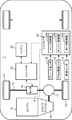
- 1 is a schematic configuration diagram of a hybrid vehicle according to an embodiment of the present invention.
- 2 is a graph showing engine characteristics (fuel consumption rate characteristics) of the hybrid vehicle shown in FIG. 1. It is a figure which shows the structure of the motor and inverter (power circuit) of the hybrid vehicle shown in FIG. It is a graph which shows the characteristic of the motor of the hybrid vehicle shown in FIG. 2 is a schematic cross-sectional view of a motor. It is a modification of the layout of a motor.
- FIG. 1 is a schematic configuration diagram of a hybrid vehicle 1 according to the present invention.
- the hybrid vehicle 1 includes a wheel 10, an axle 12 (corresponding to the wheel drive shaft of the present invention), an engine 14, a transmission 16, a differential 17, a motor 18, an inverter 20,
- the battery 22 and the controller 24 (corresponding to the control means of the present invention) are provided.
- Hybrid vehicle 1 is a so-called parallel type hybrid vehicle.
- the engine 14 and the motor 18 function as a driving source that outputs the driving force of the hybrid vehicle 1.
- traveling by only the engine 14 or traveling by only the motor 18 is realized depending on the driving conditions. . That is, traveling by both the engine and the motor is not performed.
- the motor 18 is driven only in an operating region where the required output of the vehicle is low, for example, when the vehicle starts and when it travels at a low speed immediately thereafter, and is otherwise used only for regeneration.
- the engine 14 is an in-line four-cylinder gasoline engine, and is connected to the axle 12 via a transmission 16.
- the engine 14 is set to a high compression ratio with a geometric compression ratio ⁇ of 13 to 18.
- the engine 14 has an operation region in which lean operation is performed at least in a partial load operation region (in other words, a medium load to a low load operation region).
- the excess air ratio ⁇ is 2 or more (preferably 2.5 or more) 8 or less, or G / F (air-fuel ratio indicating the ratio of EGR gas and fuel amount to fresh air amount) is 30 or more.
- the air-fuel mixture is made lean by setting it to 120 or less.
- the engine 14 is configured so that the effective expansion ratio becomes higher than the effective compression ratio of the engine 1 by setting the intake valve closing timing a predetermined amount later than the bottom dead center in the low load to medium load operation range. ing.
- the engine 14 does not perform such intake valve control in the high-load operation region, and the effective compression ratio and the effective expansion ratio are approximately the same. That is, in the engine 14, the ratio of the effective expansion ratio to the effective compression ratio is higher in the low load to medium load operation region than in the high load operation region.
- the ignition mode ignites the air-fuel mixture in the combustion chamber by driving the spark plug.
- the spark ignition mode and in other operating regions (in other words, medium to low load operating regions) where the excess air ratio ⁇ is set to 2 to 8 (or G / F is set to 30 to 120), ignition is performed.
- the mode is a compression ignition mode in which the air-fuel mixture in the combustion chamber is compressed and ignited.
- FIG. 2 is a graph showing the relationship (fuel consumption rate characteristics) between the output (kw) of the engine 14 and the fuel consumption rate (fuel consumption rate; g / kwh).
- the fuel consumption rate decreases (improves) as the output increases, and the fuel consumption rate reaches the minimum fuel consumption rate F_MIN at a specific output.
- a fuel consumption rate becomes substantially flat, and the minimum fuel consumption rate F_MIN or the fuel consumption rate close
- the output of the engine 14 showing a fuel consumption rate higher by 15% to 20% (15% in the illustrated example) than the minimum fuel consumption rate F_MIN is 10% of the maximum output. Therefore, in the driving range exceeding this output (O_10), the minimum fuel consumption rate F_MIN or a fuel consumption rate close thereto is maintained.
- the output of 10% or less of the maximum output is, for example, an output required in this hybrid vehicle 1 at a low load such as when the vehicle starts and at a subsequent low speed, and therefore in this hybrid vehicle 1.
- a low fuel consumption rate of less than 15% from the minimum fuel consumption rate F_MIN is realized.
- the motor 18 is connected to the axle 12 and connected to the battery 22 via the inverter 20. Electric power from the battery 14 is converted into AC power by the inverter 20 and supplied to the motor 18.
- the motor 18 receives this power supply and operates as an electric motor. That is, the vehicle travels when the driving force of the motor 18 is transmitted to the left and right wheels 10 via the axle 12.
- the motor 18 operates as a generator when the vehicle is decelerated.
- the AC power generated by the motor 18 is converted to DC power by the inverter 20 and then charged to the battery 22.
- the motor 18 will be described in detail later.
- the controller 24 controls the driving of the engine 14 and the motor 18 so as to obtain the driving state requested by the driver based on input signals from various sensors, and also ensures that the necessary power is ensured. Regenerative control is performed.
- the controller 24 is a controller based on a well-known microcomputer, and includes a central processing unit (CPU) that executes a program, a memory configured by, for example, RAM and ROM, and stores a program and data, and an electric signal. An input / output (I / O) bus.
- the controller 24 includes a main controller 24a, an engine controller 24b that controls the engine 14, and a motor controller 24c that controls the motor 18 (corresponding to the motor control means of the present invention) as functional configurations related to the present invention. Contains.
- the controllers 24a to 24c may be configured as individual controllers or may be configured as one controller.
- the controller 24 receives various information from a plurality of sensors provided in the vehicle.
- the vehicle 1 includes an accelerator opening sensor 30 that detects an accelerator opening corresponding to an accelerator pedal depression amount, and a brake sensor 32 that detects a brake pedal depression amount.
- a vehicle speed sensor 34 for detecting the traveling speed of the vehicle is provided, and signals from these sensors 30 to 34 are input to the controller 24.
- the controller 24, in particular, the main controller 24a calculates the driving condition, that is, the required output (drive torque) of the vehicle based on the input signals from the accelerator opening sensor 30 and the vehicle speed sensor 34, and based on the calculated required output. Thus, driving / stopping of the engine 14 and the motor 18 is determined.
- the main controller 24a determines whether or not the calculated required output of the vehicle is equal to or lower than a predetermined lower limit value. If the calculated output is equal to or lower than the lower limit value, the engine 14 is stopped and the wheels 10 are driven only by the motor 18. When this lower limit is exceeded, the wheel 10 is driven only by the engine 14.
- the lower limit value is set to a value of 10% of the maximum output of the engine 14.
- the engine 14 is driven only in an operation region (region other than the hatched region in FIG. 2) exceeding 10% of the maximum output.
- the motor 18 is driven only in the driving range where the required output of the vehicle is equal to or lower than the lower limit value, and is used only for regeneration in the driving range exceeding the lower limit value.
- the main controller 24a outputs an engine drive command signal to the engine controller 24b when driving the engine, and outputs a motor drive command signal to the motor controller 24c when driving the motor.
- the engine controller 24b sets the requested output to the target output (target drive torque), and based on the target drive torque, the throttle opening, the fuel injection pulse, etc. And a control signal is output to the throttle, injector, and the like.
- the motor controller 24c sets the required output to the target output (target drive torque), and based on the target drive torque, the inverter 20 (power described later) A control signal is output to the circuit 50). Thereby, the motor 18 is driven and controlled.
- the motor controller 24c calculates a target regenerative torque based on the signal and also supplies the inverter 20 (power circuit 50 described later) based on the target regenerative torque. Output a control signal. Thereby, the motor 18 is regeneratively controlled.
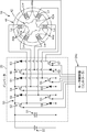
- FIG. 3 shows the configuration of the motor 18 and a power circuit 50 for supplying electric power thereto.
- a switched reluctance motor (hereinafter referred to as an SR motor) is used as the motor 18.
- the motor 18 includes a rotor 42 having a plurality of rotor salient pole portions 42a made of a magnetic material that protrudes radially outward, and a plurality of stator protrusions that are provided so as to surround the rotor 42 and protrude inward. And a stator 44 having a pole portion 44a.
- the rotor 42 is made of an iron core and has four rotor salient pole portions 42a.
- stator 44 has six stator salient pole portions 44a, and each stator salient pole portion 44a is wound to have three-phase excitation coils Lu, Lv, and Lw of U, V, and W phases. Is forming. That is, in the motor 18, the exciting coils Lu, Lv, and Lw of the stator 44 are energized in order, and the rotor salient pole portion 42a is magnetically attracted to the stator salient pole portion 44a, so that the drive torque and regeneration are applied to the rotor 42. Torque is generated.
- the power circuit 50 supplies power of the battery 22 to the motor 18 by PWM control by the motor controller 24c, that is, supplies power to the excitation coils Lu, Lv, and Lw.
- the power circuit 50 is included in the inverter 20.
- the power circuit 50 includes a capacitor 51, a first circuit unit having an IGBT (insulated gate bipolar transistor) 52 and a diode 58 connected in series with each other, and a second circuit unit having an IGBT 53 and a diode 59 connected in series with each other.
- a third circuit unit having an IGBT 54 and a diode 60 connected in series with each other, a fourth circuit unit having an IGBT 55 and a diode 61 connected in series with each other, and an IGBT 56 and a diode 62 connected in series with each other.
- One end of the coil Lu of the motor 18 is connected to the connection point between the IGBT 52 and the diode 58 in the first circuit unit, and the other end of the coil Lu is connected to the connection point between the IGBT 53 and the diode 59 in the second circuit unit.
- one end of the coil Lv of the motor 18 is connected to the connection point between the IGBT 54 and the diode 60 in the third circuit unit, and the other end of the coil Lv is connected to the connection point between the IGBT 55 and the diode 61 in the fourth circuit unit.
- one end of the coil Lw of the motor 18 is connected to the connection point between the IGBT 56 and the diode 62 in the fifth circuit unit, and the other end of the coil Lw is connected to the connection point between the IGBT 57 and the diode 63 in the sixth circuit unit. Is done.
- a control signal (PWM signal) having a duty ratio corresponding to the target drive torque / target regeneration torque is sent from the motor controller 24 c to the IGBTs 52, 54, 56 of the power circuit 50.
- PWM signal a control signal having a duty ratio corresponding to the target drive torque / target regeneration torque
- the IGBTs 52, 54, and 56 are turned on and off.
- a control signal for switching on / off of the IGBTs 53, 55, 57 is output from the motor controller 24c to the IGBTs 53, 55, 57 based on the rotation angle of the rotor 42 output from a rotation angle sensor (not shown) of the motor 18.
- FIG. 4 shows the relationship between the motor speed and torque (drive torque / regenerative torque) of the motor 18 (SR motor) when the motor load is 10% or more of the maximum load, and the motor speed and torque of the IPM motor. Shows the relationship.
- the solid line indicates the motor 18 (SR motor)
- the chain line indicates the IPM motor
- the broken line indicates the iso-output line.
- the motor 18 (SR motor) is still along the iso-output line even when the rotational speed S_IPM is exceeded, and the torque decreases gradually even in a region outside the iso-output line, which is higher. High torque can be obtained up to the rotational speed range.
- the motor 18 of this example when the motor load is 10% or more of the maximum load, the rotation is 75% of the maximum motor rotation speed S_MAX that is the maximum rotation speed that can be structurally compensated for a temperature rise or the like.
- the motor efficiency that is, the ratio of the generated torque T_SR of the motor 18 to the theoretical maximum output torque T_0 in the rotation speed S_75 is ensured to be 90% or more.
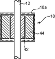
- the motor 18 is directly connected to the axle 12 without passing through the transmission 16, as shown in FIG.
- the motor 18 is a so-called hollow structure motor (hollow motor).
- the stator 44 is fixed to the inner peripheral surface of a cylindrical housing 18 a, and the stator 44 is disposed inside the stator 44.
- the rotor 42 is arranged.
- the motor 18 is disposed with respect to the axle 12 so that the axle 12 penetrates the rotor 42 and the stator 44, and the rotor 42 is fixed to the axle 12. Thereby, after the motor 18 is arranged on the same axis as the axle 12, the motor 18 is directly connected to the axle 12.
- the motor 18 is directly connected to the axle 12 at a position between the differential 17 and the wheel 10 without passing through the transmission 16 as described above. Therefore, driving of the wheel 10 by the motor 18 and recovery of regenerative power can be performed more efficiently. That is, when the motor 18 is driven, the driving force can be directly transmitted to the axle 12 without being lost by the transmission 16 or the like. On the other hand, when the motor 18 is regenerated, the kinetic energy at the time of braking is lost by the transmission 16 or the like. Without being input from the axle 12 to the motor 18.
- the SR motor having the motor characteristics that the motor efficiency at the rotation speed that is 75% of the maximum rotation speed is 90% or more is used as the motor 18. Since it is applied, the kinetic energy of the axle 12 rotating at high speed can be effectively recovered as regenerative power during high-speed traveling. Therefore, according to the hybrid vehicle 1, the kinetic energy generated by the motor 18 can be efficiently traveled by the hybrid vehicle 1 as compared with a conventional hybrid vehicle of this type in which the IPM motor is connected to the axle via the transmission. It can be used, and the kinetic energy at the time of braking can be recovered more efficiently as regenerative power.
- the hybrid vehicle 1 also includes an engine 14 having a fuel consumption rate characteristic in which the engine output showing a fuel consumption rate 15% higher than the minimum fuel consumption rate is only 10% or less of the maximum output, and the required output of the vehicle is In the driving range where the maximum output of the engine 14 is 10% or less (the driving range where the fuel consumption rate of the engine 14 is 15% or more higher than the minimum fuel consumption rate F_MIN), the engine 14 is stopped and the vehicle runs only with the motor 18, and the required output is In the driving range exceeding 10% of the maximum output (the driving range where the fuel consumption rate of the engine 14 is less than 15% from the minimum fuel consumption rate F_MIN), the engine 14 alone travels.
- the engine 14 is driven only in the driving range showing a low fuel consumption rate of less than 15% from the minimum fuel consumption rate F_MIN, while the motor 18 is driven at a low speed after the vehicle starts. Drives only when the load is low such as when driving. Therefore, it is possible to apply a small motor with a relatively low output while maintaining a low fuel consumption rate in the entire driving range, thereby reducing the vehicle weight and thus improving the fuel consumption rate and lowering the vehicle cost. There is also an advantage that it can be achieved.
- the control burden on the controller 24 can be reduced. That is, in the conventional hybrid vehicle in which the motor is connected to the axle via the transmission, complicated torque control is required so that the motor generates an appropriate torque (drive torque / regenerative torque) following the transmission switching.
- the burden of control by the controller 24 can be reduced by the amount that such complicated torque control is unnecessary.
- the motor 18 since the motor 18 is directly connected to the axle 12 without passing through the transmission 16, the motor 18 is disposed in the engine room in a relatively roomy area behind the engine. Can do.
- the motor 18 is disposed coaxially with the axle 12 so that the axle 12 penetrates the inside of the motor 18, so that a space occupied by the motor 18 and the axle 12 is partially. Duplicate. Accordingly, there is an advantage that the motor 18 can be efficiently arranged in a narrow space.
- the motor 18 is connected to the axle 12 at a position between the differential 17 and the right wheel 10 in the axle 12. , And may be connected to the axle 12 at a position between the differential 17 and the right wheel 10.
- a motor 18 of a type in which the rotor rotation shaft projects to the outside is applied, and the rotor rotation shaft and the axle 12 are parallel to each other at a position behind the axle 12 as shown in FIG. Then, after the motor 18 is arranged, the motor 18 may be connected to the axle 12 via a PTO (Power Take Off) 19.
- the motor 18 may be arranged in a state where the rotor rotation shaft and the axle 12 are orthogonal to each other.
- the motor 18 may be arranged in a relatively ample space between the driver's seat and the passenger seat.
- the hybrid vehicle 1 of the present invention has been described above, the hybrid vehicle 1 is an example of a preferred embodiment of the hybrid vehicle according to the present invention, and the specific configuration thereof does not depart from the gist of the present invention. It can be changed as appropriate.
- the present invention is a parallel hybrid vehicle.
- This hybrid vehicle is an engine and a regenerative travel motor, and when the load is 10% or more of the maximum load, the motor efficiency at the rotation speed that is 75% of the maximum rotation speed is 90% or more.
- the motor includes a motor exhibiting motor characteristics and a transmission that transmits the power of the engine to a wheel drive shaft, and the motor is connected to the wheel drive shaft without passing through the transmission.
- the motor since the motor is connected to the wheel drive shaft without passing through the transmission, the kinetic energy at the time of braking can be input to the motor without being lost by the transmission.
- the motor since the motor has a motor characteristic that the motor efficiency is 90% or more at the rotational speed that is 75% of the maximum rotational speed when the load is 10% or more of the maximum load, the high rotational speed that is difficult for the IPM motor.
- the regenerative torque can be efficiently generated even in the region, and therefore the kinetic energy of the wheel rotating at high speed can be effectively recovered as regenerative power.
- the motor efficiency is 90% or more at the rotation speed that is 75% of the maximum rotation speed. It is suitable as a motor for a hybrid vehicle.
- the engine has a fuel consumption rate characteristic in which the engine output showing a fuel consumption rate 15 to 20% higher than the lowest fuel consumption rate is only in the driving range of 10% or less of the maximum output. Is preferred.
- the engine in the driving range where the engine output exceeds 10% of the maximum output, the engine always maintains a low fuel consumption rate (low fuel consumption per engine output), so the vehicle runs on the engine in a wide driving range. And it becomes possible to restrict
- a control unit that controls the driving of the engine and the motor is provided, and the control unit calculates a target output of the engine according to an operating state of the hybrid vehicle, and the target output is the highest output.
- the control unit calculates a target output of the engine according to an operating state of the hybrid vehicle, and the target output is the highest output.
- the engine is stopped and the hybrid vehicle is driven by the motor.
- the hybrid vehicle is driven by the engine.
- the motor is driven only at the time of starting the vehicle and traveling at a low speed immediately thereafter, and the motor is used only for regeneration (power generation) in other operating regions. Therefore, it is possible to apply a small motor with a low output as the motor, which makes it possible to reduce the weight of the vehicle, improve the fuel efficiency, and reduce the vehicle cost.
- the motor has a hollow structure and is arranged coaxially with respect to the wheel drive shaft with the wheel drive shaft passing through the inside thereof.
- This configuration is advantageous in terms of layout because the motor can be compactly arranged coaxially with the wheel drive shaft.
- the motor may be connected to the wheel drive shaft in a state where the rotor rotation shaft is orthogonal to the wheel drive shaft.
Abstract
ハイブリッド車は、エンジンと、回生可能な走行用のモータであって、負荷が最大負荷の10%以上であるとき、最高回転数の75%となる回転数におけるモータ効率が90%以上となるモータ特性を示すモータと、前記エンジンの動力を車輪駆動軸に伝達するトランスミッションと、を含み、前記モータは、前記トランスミッションを介することなく前記車輪駆動軸に連結されている。
Description
本発明は、ハイブリッド車に関するものである。
従来、エンジンと回生可能なモータとを備え、主にエンジンを用いて車輪を駆動しながら、要求出力に応じてモータを駆動するパラレル式のハイブリッド車が知られている(例えば、特許文献1)。このハイブリッド車は、車両の要求出力がエンジンの燃費率(燃料消費率)が極めて高い低出力側の運転域ではエンジンを停止させてモータのみで車輪を駆動し、それ以外の運転域では、燃費率が低い運転領域でエンジンを駆動することによりエンジンとモータとを併用して燃費の改善を図る。他方、このハイブリッド車は、車両の減速時には、モータの回生制動により運動エネルギーを電力(回生電力)に変換して蓄電(回収)することで、モータ駆動用の電力を確保する。
このハイブリッド車では、モータがトランスミッションを介してプロペラシャフト等の駆動軸に連結されており、三相誘導電動機等のIPMモータ(Interior Permanent MagnetSyncronous モータ)が用いられるこの種のハイブリッド車にとっては都合の良い構成となっている。すなわち、IPMモータは、その構造上、逆起電力が発生するため、高い回転数領域でトルクを発生させることが難しいが、上記のようにトランスミッションに連結されて、モータの回転数域が制限されることで、広い速度域に亘ってトルクを支障なく発生させること、つまり動力の出力および回生を行うことが可能になっている。
しかし、モータがトランスミッションを介して駆動軸に連結される上記従来のハイブリッド車では、高速走行の制動時など、車輪が高速で回転しているにも拘わらず、モータは、トランスミッションにより制限された回転数の範囲内でしか回生電力を回収することができない。つまり、高速回転する車輪の運動エネルギーを必ずしも効率良く回生電力として回収できているとは言えなかった。また、上記従来のハイブリッド車では、トランスミッションを経由してモータに運動エネルギーが入力されるため、ここでエネルギーロスが生じる。従って、この点でも、運動エネルギーを効率良く回生電力として回収することが難しかった。
本発明は、ハイブリッド車において、走行中の運動エネルギーをより効率良く回生電力として回収することを目的とする。
そして、本発明の一の局面に係るパラレル式のハイブリッド車は、エンジンと、回生可能な走行用のモータであって、負荷が最大負荷の10%以上であるとき、最高回転数の75%となる回転数におけるモータ効率が90%以上となるモータ特性を示すモータと、前記エンジンの動力を車輪駆動軸に伝達するトランスミッションと、を含み、前記モータが、前記トランスミッションを介することなく前記車輪駆動軸に連結されているものである。
以下、添付図面を参照しながら本発明の好ましい実施の一形態について詳述する。
図1は、本発明に係るハイブリッド車1の概略構成図である。同図に示すように、ハイブリッド車1は、車輪10と、車軸12(本発明の車輪駆動軸に相当する)と、エンジン14と、トランスミッション16と、デフ17と、モータ18と、インバータ20と、バッテリ22と、コントローラ24(本発明の制御手段に相当する)と、を備えている。
ハイブリッド車1は、いわゆるパラレル式のハイブリッド車である。エンジン14およびモータ18は、ハイブリッド車1の駆動力を出力する駆動源として機能し、このハイブリッド車1では、運転条件に応じて、エンジン14のみによる走行、又はモータ18のみによる走行が実現される。つまり、エンジンとモータの双方による走行は行われない。なお、後述する通り、モータ18は、車両の要求出力が低い運転域、例えば車両の発進時及びその直後の低速走行時にのみ駆動され、それ以外は、回生にのみ用いられる。
エンジン14は、直列四気筒のガソリンエンジンであり、トランスミッション16を介して車軸12に連結されている。
詳細図を省略するが、エンジン14は、幾何学的圧縮比εが13以上18以下の高圧縮比に設定されている。また、エンジン14は、少なくとも部分負荷の運転領域(換言すれば、中負荷乃至低負荷の運転領域)においては、リーン運転を行う運転領域を有する。この運転領域では、空気過剰率λを2以上(好ましくは、2.5以上)8以下に、又は、G/F(EGRガス及び新気量に対する燃料量の比を示す空燃比)を30以上120以下に設定して、混合気をリーン化している。
また、エンジン14は、低負荷乃至中負荷領域の運転領域では、吸気弁閉時期を下死点より所定量遅く設定することによって、エンジン1の有効圧縮比よりも有効膨張比が高くなるようにしている。一方、エンジン14は、高負荷の運転領域においては、そのような吸気弁制御を行っておらず、有効圧縮比と有効膨張比が概ね一致している。つまり、このエンジン14は、有効圧縮比に対する有効膨張比の比率が、高負荷の運転領域に比べて、低負荷乃至中負荷の運転領域の方が高くなっている。
また、このエンジン14では、温間時に、全負荷を含む高負荷の運転領域において空気過剰率をλ=1にする場合は、点火モードが、点火プラグの駆動によって燃焼室内の混合気に点火する火花点火モードとされ、空気過剰率λを2~8(又はG/Fを30~120)に設定するような、それ以外の運転領域(換言すると中負荷乃至低負荷の運転領域)では、点火モードが、燃焼室内の混合気を圧縮着火させる圧縮着火モードとされる。
こうような構成により、エンジン14は、その図示熱効率が高められて、燃費性能が大幅に向上したものとなっている。図2は、このエンジン14の出力(kw)と燃費率(燃料消費率;g/kwh)との関係(燃費率特性)を示すグラフである。同図に示すように、このエンジン14では、出力の上昇に伴い燃費率が低下し(向上し)、特定の出力で燃費率が最低燃費率F_MINに達する。そして、当該出力を超える運転域では燃費率がほぼ横這いとなり、最低燃費率F_MIN又はそれに近い燃費率が維持される。例えば、このエンジン14では、最低燃費率F_MINよりも15%~20%(図示の例では15%)高い燃費率を示す当該エンジン14の出力は最高出力の10%である。従って、この出力(O_10)を超える運転域では、最低燃費率F_MIN又はそれ近い燃費率が維持される。
ここで、最高出力の10%以下の出力とは、例えばこのハイブリッド車1では、車両の発進時およびその後の低速走向時などの低負荷時に要求される出力であり、従って、このハイブリッド車1では、中負荷から高負荷に亘る運転域では、最低燃費率F_MINから15%未満の低い低燃費率が実現されている。
前記モータ18は、車軸12に連結されているとともに、インバータ20を介してバッテリ22に接続されている。モータ18には、バッテリ14からの電力がインバータ20により交流電力に変換されて供給される。モータ18は、この電力供給を受けて電動機として作動する。つまり、モータ18の駆動力が、車軸12を介して左右の車輪10に伝達されることにより車両が走行する。なお、モータ18は、車両の減速時には、発電機として作動する。モータ18で発生した交流電力は、インバータ20で直流電力に変換され後にバッテリ22に充電される。なお、このモータ18については後に詳述する。
前記コントローラ24は、各種センサからの入力信号に基づいて、ドライバの要求する走行状態が得られるようにエンジン14やモータ18の駆動制御を行うとともに、必要な電力が確保されるようにモータ18の回生制御などを行うものである。このコントローラ24は、周知のマイクロコンピュータをベースとするコントローラであって、プログラムを実行する中央演算処理装置(CPU)と、例えばRAMやROMにより構成されてプログラム及びデータを格納するメモリと、電気信号の入出力をする入出力(I/O)バスと、を備えている。コントローラ24は、本発明に関する機能構成として、メイン制御器24aと、エンジン14を制御するエンジン制御器24bと、モータ18を制御するモータ制御器24c(本発明のモータ制御手段に相当する)とを含んでいる。なお、各制御器24a~24cは、互いに個別のコントローラとして構成されていてもよく、1つのコントローラとして構成されていてもよい。
このコントローラ24には、車両に設けられた複数のセンサから種々の情報が入力されている。本発明の説明に必要な範囲で説明すると、車両1には、アクセルペダルの踏込み量に対応したアクセル開度を検出するアクセル開度センサ30と、ブレーキペダルの踏み込み量を検出するブレーキセンサ32と、車両の走行速度を検出する車速センサ34とが設けられており、これらセンサ30~34からの信号がコントローラ24に入力されている。
コントローラ24、特に、メイン制御器24aは、前記アクセル開度センサ30および車速センサ34からの入力信号に基づいて運転条件、すなわち車両の要求出力(駆動トルク)を算出し、算出した要求出力に基づいて、エンジン14およびモータ18の駆動/停止を決定する。ここで、メイン制御器24aは、算出した車両の要求出力が所定の下限値以下か否かを判定し、下限値以下であれば、エンジン14を停止してモータ18のみで車輪10を駆動し、この下限値を超えている場合には、エンジン14のみで車輪10を駆動する。当例では、上記下限値は、エンジン14の最高出力の10%の値に設定されている。従って、このハイブリッド車1では、エンジン14は、その最高出力の10%を超える運転域(図2のハッチング領域以外の領域)でのみ駆動される。他方、モータ18は、車両の要求出力が上記下限値以下の運転域でのみ駆動され、当該下限値を超える運転域では回生にのみ用いられる。
メイン制御器24aは、エンジンを駆動させる際には、エンジンの駆動指令信号をエンジン制御器24bに出力し、モータを駆動させる際には、モータの駆動指令信号をモータ制御器24cに出力する。
エンジン制御器24bは、車両の要求出力が前記下限値を超える場合には、要求出力を目標出力(目標駆動トルク)に設定するとともに、当該目標駆動トルクに基づいてスロットル開度、燃料噴射パルス等を算出し、スロットル、インジェクタ等に制御信号を出力する。
また、モータ制御器24cは、車両の要求出力が前記下限値以下の場合には、当該要求出力を目標出力(目標駆動トルク)に設定するとともに、当該目標駆動トルクに基づいてインバータ20(後記パワー回路50)に制御信号を出力する。これによりモータ18を駆動制御する。また、ブレーキセンサ32からの信号入力があった場合には、モータ制御器24cは、その信号に基づき目標回生トルクを算出するとともに、当該目標回生トルクに基づいてインバータ20(後記パワー回路50)に制御信号を出力する。これによりモータ18を回生制御する。
図3は、前記モータ18とこれに電力を供給するパワー回路50の構成を示している。
当例では、モータ18として、スイッチトリラクタンスモータ(以下、SRモータという)が用いられている。このモータ18は、径方向外側に向かって突出する磁性体からなる複数のロータ突極部42aを備えるロータ42と、このロータ42を囲むように設けられ、内側に向かって突出する複数のステータ突極部44aを有するステータ44とを備える。当例では、ロータ42は鉄芯からなり、4つのロータ突極部42aを有する。また、ステータ44は、6つのステータ突極部44aを有しており、各ステータ突極部44aは、それぞれ、巻線されてU、V、W相の三相の励磁コイルLu、Lv、Lwを形成している。つまり、このモータ18では、ステータ44の各励磁コイルLu、Lv、Lwに順番に通電され、ステータ突極部44aにロータ突極部42aが磁気吸引されることで、ロータ42に駆動トルクおよび回生トルクが発生する。
前記パワー回路50は、前記モータ制御器24cによるPWM制御によりバッテリ22の電力をモータ18に供給するもの、つまり、各励磁コイルLu、Lv、Lwへの通電を行うものである。このパワー回路50は、前記インバータ20に含まれている。
パワー回路50は、コンデンサ51と、互い直列に接続されたIGBT(絶縁ゲートバイポーラトランジスタ)52及びダイオード58を有する第1回路部と、互いに直列に接続されたIGBT53及びダイオード59を有する第2回路部と、互いに直列に接続されたIGBT54及びダイオード60を有する第3回路部と、互いに直列に接続されたIGBT55及びダイオード61を有する第4回路部と、互いに直列に接続されたIGBT56及びダイオード62を有する第5回路部と、互いに直列に接続されたIGBT57及びダイオード63を有する第6回路部とを有し、これらコンデンサ51及び回路部等がバッテリ4に対して各々並列に接続された回路構成を有する。そして、第1回路部のIGBT52とダイオード58との接続点に、モータ18のコイルLuの一端が接続され、第2回路部のIGBT53とダイオード59との接続点に、コイルLuの他端が接続されている。また、第3回路部のIGBT54とダイオード60との接続点に、モータ18のコイルLvの一端が接続され、第4回路部のIGBT55とダイオード61との接続点に、コイルLvの他端が接続されている。さらに、第5回路部のIGBT56とダイオード62との接続点に、モータ18のコイルLwの一端が接続され、第6回路部のIGBT57とダイオード63との接続点に、コイルLwの他端が接続される。
つまり、モータ18を駆動/回生制御する場合には、モータ制御器24cから目標駆動トルク/目標回生トルクに応じたデューティ比を有する制御信号(PWM信号)がパワー回路50のIGBT52、54、56に出力されることにより、当該IGBT52、54、56がオン、オフされる。また、モータ18の図外の回転角センサから出力されるロータ42の回転角に基づき、IGBT53、55、57のオンオフを切り替える制御信号がモータ制御器24cからIGBT53、55、57に出力される。
なお、このモータ18(SRモータ)には、ロータ42やステータ44に永久磁石が用いられておらず、よって、IPMモータのような逆起電力が発生しない。そのため、このモータ18では、IPMモータよりも高回転数域まで高いモータ効率が維持される。図4に、モータ負荷が最大負荷の10%以上であるときのモータ18(SRモータ)のモータ回転数とトルク(駆動トルク/回生トルク)との関係、および、IPMモータのモータ回転数とトルクとの関係を示す。図4において、実線はモータ18(SRモータ)を、鎖線はIPMモータを、破線は等出力線を示している。
図4に示されるように、IPMモータでは、回転数がS_IPMになるとトルクが急激に低下して等出力線を外れる。これに対して、モータ18(SRモータ)は、回転数S_IPMを越えてもなお等出力線に沿っているとともに、等出力線から外れた領域においてもそのトルクの低下は緩やかであり、より高い回転数域まで高いトルクを得ることができる。具体的には、当例のモータ18では、モータ負荷が最大負荷の10%以上であるとき、温度上昇等に対する構造上補償可能な最大回転数であるモータ最高回転数S_MAXの
75%となる回転数S_75において、モータ効率、すなわち、回転数S_75における理論上の最大出力トルクT_0に対するモータ18の発生トルクT_SRの割合が90%以上確保される。
75%となる回転数S_75において、モータ効率、すなわち、回転数S_75における理論上の最大出力トルクT_0に対するモータ18の発生トルクT_SRの割合が90%以上確保される。
なお、このハイブリッド車1では、前記モータ18は、図1に示すように、トランスミッション16を介すことなく車軸12に直接連結されている。詳しくは、図5に示すように、モータ18は、いわゆる中空構造のモータ(中空モータ)であり、例えば円筒状のハウジング18aの内周面に前記ステータ44が固定され、このステータ44の内側に前記ロータ42が配置された構造を有している。そして、車軸12がロータ42及びステータ44を貫通するように当該車軸12に対してモータ18が配置された上で、前記ロータ42が車軸12に固定されている。これにより、車軸12の同軸上にモータ18が配置された上で、当該モータ18が車軸12に直接連結されている。
以上のようなハイブリッド車1によれば、上記の通り、モータ18がトランスミッション16を介すことなく、デフ17と車輪10との間の位置で直接車軸12に連結されている。そのため、モータ18による車輪10の駆動や回生電力の回収をより効率良く行うことができる。すなわち、モータ18の駆動時には、その駆動力をトランスミッション16等でロスすることなく車軸12に直接伝達することができ、他方、モータ18の回生時には、制動時の運動エネルギーをトランスミッション16等でロスすることなく車軸12からモータ18に入力することができる。しかも、このハイブリッド車1では、モータ負荷が最大負荷の10%以上のとき、最高回転数の75%となる回転数におけるモータ効率が90%以上となるモータ特性を有するSRモータが上記モータ18として適用されているので、高速走行中、高速回転する車軸12の運動エネルギーを効果的に回生電力として回収することができる。従って、このハイブリッド車1によれば、IPMモータがトランスミッションを介して車軸に連結されている従来のこの種のハイブリッド車と比べると、モータ18が発生する運動エネルギーを効率良くハイブリッド車1の走行に使用することができるとともに、制動時の運動エネルギーをより効率良く回生電力として回収することができる。
また、このハイブリッド車1は、最低燃費率よりも15%高い燃費率を示すエンジン出力が最高出力の10%以下の運転域のみとなる燃費率特性を有するエンジン14を備え、車両の要求出力がエンジン14の最高出力の10%以下の運転域(エンジン14の燃費率が最低燃費率F_MINから15%以上高い運転域)では、エンジン14を停止させてモータ18のみで走行し、要求出力が前記最高出力の10%を超える運転域(エンジン14の燃費率が最低燃費率F_MINから15%未満の運転域)では、エンジン14のみで走行する。つまり、このハイブリッド車1によれば、エンジン14を、最低燃費率F_MINから15%未満の低い燃費率を示す運転域でのみ駆動する一方で、モータ18については、車両の発進時およびその後の低速走向時などの低負荷時にのみ駆動する。従って、全運転域において低い燃費率を維持しながらも、比較的低出力の小型モータを適用することが可能であり、これにより車両重量の軽減、ひいては燃費率の向上や車両コストの低廉化を図ることができるという利点もある。
また、上記ハイブリッド車1によれば、モータ18がトランスミッション16を介さずに直接車軸12に連結されているため、コントローラ24(モータ制御器24c)による制御負担を軽減することもできる。すなわち、モータがトランスミッションを介して車軸に連結されている従来のハイブリッド車では、トランスミッションの切り替えに追従してモータが適正トルク(駆動トルク/回生トルク)を発生するように複雑なトルク制御が必要となるが、このハイブリッド車1によれば、このような複雑なトルク制御が不要となる分、コントローラ24(モータ制御器24c)による制御負担を軽減することができる。
さらに、このハイブリッド車1によれば、モータ18がトランスミッション16を介さずに直接車軸12に連結されるため、エンジンルーム内のうち、エンジン後方の比較的余裕のある場所にモータ18を配置することができる。特に、このハイブリッド車1では、車軸12がモータ18の内側を貫通するように当該モータ18が車軸12に対してその同軸上に配置されることで、モータ18と車軸12の占有スペースが一部重複する。従って、狭いスペースにモータ18を効率良く配置することができるという利点もある。
なお、この実施形態のハイブリッド車1では、図1に示すように、モータ18は、車軸12のうち、デフ17と右側の車輪10との間の位置で車軸12に連結されているが、例えば、デフ17と右側の車輪10との間の位置で車軸12に連結されていてもよい。
また、ロータ回転軸が外部に突出するタイプのモータ18を適用し、図6(a)に示すように、車軸12よりも車両後方の位置に、ロータ回転軸と車軸12とが平行になる状態でモータ18を配置した上で、当該モータ18をPTO(Power Take Off)19を介して車軸12に連結するようにしてもよい。この場合、図6(b)に示すように、ロータ回転軸と車軸12とが直交する状態でモータ18を配置してもよい。この場合さらに、同図中の二点鎖線に示すように、運転席と助手席の間の比較的余裕のあるスペースを利用してモータ18を配置することも考えられる。
以上、本発明のハイブリッド車1について説明したが、このハイブリッド車1は、本発明に係るハイブリッド車の好ましい実施形態の例示であって、その具体的な構成は、本発明の要旨を逸脱しない範囲で適宜変更可能である。
以上説明した本発明をまとめると以下の通りである。
本発明は、パラレル式のハイブリッド車である。このハイブリッド車は、エンジンと、回生可能な走行用のモータであって、負荷が最大負荷の10%以上であるとき、最高回転数の75%となる回転数におけるモータ効率が90%以上となるモータ特性を示すモータと、前記エンジンの動力を車輪駆動軸に伝達するトランスミッションと、を含み、前記モータが、前記トランスミッションを介することなく前記車輪駆動軸に連結されているものである。
このハイブリッド車によれば、モータがトランスミッションを介すことなく車輪駆動軸に連結されているため、制動時の運動エネルギーをトランスミッションでロスすることなくモータに入力することができる。しかも、モータは、負荷が最大負荷の10%以上であるとき、最高回転数の75%となる回転数におけるモータ効率が90%以上となるモータ特性を有するため、IPMモータでは困難な高い回転数領域でも効率良く回生トルクを発生させることが可能であり、従って、高速回転する車輪の運動エネルギーを効果的に回生電力として回収することが可能となる。
この場合、スイッチトリラクタンスモータによれば、負荷が最大負荷の10%以上であるとき、最高回転数の75%となる回転数におけるモータ効率が90%以上という上記のモータ特性を備えるため、上記ハイブリッド車のモータとして好適である。
なお、このハイブリッド車において、前記エンジンは、最低燃費率よりも15~20%高い燃費率を示すエンジン出力が最高出力の10%以下の運転域のみとなる燃費率特性を有するものであるのが好適である。
この構成によれば、エンジン出力が最高出力の10%を超える運転域では、常にエンジンが低い燃費率率(エンジン出力当たりの燃料消費量少)を維持するため、広い運転域でエンジンにより車両走行し、モータに求められる運転域を、車両の要求出力が極低い運転域に制限することが可能となる。
この場合、例えば前記エンジンおよび前記モータの駆動を制御する制御手段を備え、この制御手段は、当該ハイブリッド車の運転状態に応じて前記エンジンの目標出力を算出し、この目標出力が前記最高出力の10%以下となる運転領域では、前記エンジンを停止させて当該ハイブリッド車を前記モータで走行させる一方、前記最高出力の10%を超える運転領域では、前記エンジンで当該ハイブリッド車を走行させ、前記モータには回生動作のみ行わせる、ように構成することができる。
この構成によれば、車両の発進及びその直後の低速走行時などにのみモータが駆動され、それ以外の運転域では、モータは回生(発電)にのみ用いられる。そのため、モータとして低出力の小型モータを適用することが可能となり、これにより、車重の軽量化ひいては燃費率の向上や車両コストの低廉化を図ることが可能となる。
なお、上記のハイブリッド車において、前記モータは、中空構造を有し、その内側を前記車輪駆動軸が貫通する状態で当該車輪駆動軸に対して同軸上に配置されているのが好適である。
この構成によれば、モータを車輪駆動軸と同軸上にコンパクトに配置することが可能となるため、レイアウト面で有利となる。
また、上記のハイブリッド車において、前記モータは、ロータ回転軸が前記車輪駆動軸に対して直交する状態で当該車輪駆動軸に連結されているものであってもよい。
この構成によれば、運転席と助手席の間のスペース等を利用してモータを配置するなど、車両の空きスペースを有効に使ってモータを配置することが可能となる。
Claims (6)
- パラレル式のハイブリッド車であって、
エンジンと、
回生可能な走行用のモータであって、負荷が最大負荷の10%以上であるとき、最高回転数の75%となる回転数におけるモータ効率が90%以上となるモータ特性を示すモータと、
前記エンジンの動力を車輪駆動軸に伝達するトランスミッションと、を含み、
前記モータは、前記トランスミッションを介することなく前記車輪駆動軸に連結されている、ことを特徴とするハイブリッド車。 - 請求項1に記載のハイブリッド車において、
前記モータは、スイッチトリラクタンスモータであることを特徴とするハイブリッド車。 - 請求項1又は2に記載のハイブリッド車において、
前記エンジンは、最低燃費率よりも15~20%高い燃費率を示すエンジン出力が最高出力の10%以下の運転域のみとなる燃費率特性を有する、ことを特徴とするハイブリッド車。 - 請求項3に記載のハイブリッド車において、
前記エンジンおよび前記モータの駆動を制御する制御手段を備え、この制御手段は、当該ハイブリッド車の運転状態に応じて前記エンジンの目標出力を算出し、この目標出力が前記最高出力の10%以下となる運転領域では、前記エンジンを停止させて当該ハイブリッド車を前記モータで走行させる一方、前記10%以下の運転領域を除く運転領域では、前記エンジンで当該ハイブリッド車を走行させ、前記モータには回生動作のみ行わせることを特徴とするハイブリッド車。 - 請求項1乃至4の何れか一項に記載のハイブリッド車において、
前記モータは、中空構造を有し、その内側を前記車輪駆動軸が貫通する状態で当該車輪駆動軸に対して同軸上に配置されていることを特徴とするハイブリッド車。 - 請求項1乃至4の何れか一項に記載のハイブリッド車において、
前記モータは、ロータ回転軸が前記車輪駆動軸に対して直交する状態で当該車輪駆動軸に連結されていることを特徴とするハイブリッド車。
Priority Applications (1)
| Application Number | Priority Date | Filing Date | Title |
|---|---|---|---|
| US14/895,730 US9868433B2 (en) | 2013-06-07 | 2014-06-03 | Hybrid vehicle |
Applications Claiming Priority (2)
| Application Number | Priority Date | Filing Date | Title |
|---|---|---|---|
| JP2013-120795 | 2013-06-07 | ||
| JP2013120795A JP2014237372A (ja) | 2013-06-07 | 2013-06-07 | ハイブリッド車 |
Publications (1)
| Publication Number | Publication Date |
|---|---|
| WO2014196507A1 true WO2014196507A1 (ja) | 2014-12-11 |
Family
ID=52008148
Family Applications (1)
| Application Number | Title | Priority Date | Filing Date |
|---|---|---|---|
| PCT/JP2014/064668 WO2014196507A1 (ja) | 2013-06-07 | 2014-06-03 | ハイブリッド車 |
Country Status (3)
| Country | Link |
|---|---|
| US (1) | US9868433B2 (ja) |
| JP (1) | JP2014237372A (ja) |
| WO (1) | WO2014196507A1 (ja) |
Families Citing this family (3)
| Publication number | Priority date | Publication date | Assignee | Title |
|---|---|---|---|---|
| KR101703601B1 (ko) * | 2015-07-13 | 2017-02-22 | 현대자동차 주식회사 | 차량의 제어방법 |
| JP6881350B2 (ja) | 2018-02-28 | 2021-06-02 | トヨタ自動車株式会社 | スイッチトリラクタンスモータの制御装置 |
| JP7003777B2 (ja) * | 2018-03-23 | 2022-01-21 | トヨタ自動車株式会社 | ハイブリッド車両の制御装置 |
Citations (4)
| Publication number | Priority date | Publication date | Assignee | Title |
|---|---|---|---|---|
| JPS59204402A (ja) * | 1983-05-06 | 1984-11-19 | Nissan Motor Co Ltd | ハイブリッド自動車用走行制御装置 |
| JP2000050584A (ja) * | 1998-07-27 | 2000-02-18 | Matsushita Electric Ind Co Ltd | 電動機 |
| JP2002160540A (ja) * | 2000-11-28 | 2002-06-04 | Aisin Seiki Co Ltd | ハイブリッド車用駆動装置 |
| JP2006159974A (ja) * | 2004-12-03 | 2006-06-22 | Toyota Motor Corp | 旋回走行を助ける電動発電機を備えた車輌とその運転方法 |
Family Cites Families (5)
| Publication number | Priority date | Publication date | Assignee | Title |
|---|---|---|---|---|
| US4305254A (en) * | 1980-02-20 | 1981-12-15 | Daihatsu Motor Co., Ltd. | Control apparatus and method for engine/electric hybrid vehicle |
| US6554088B2 (en) * | 1998-09-14 | 2003-04-29 | Paice Corporation | Hybrid vehicles |
| JP2000343965A (ja) | 1999-06-08 | 2000-12-12 | Nissan Diesel Motor Co Ltd | ハイブリッド車両 |
| GB2389827B (en) * | 2002-06-18 | 2005-12-14 | Magnetic Systems Technology Lt | Hub drive system |
| JP2013056620A (ja) * | 2011-09-08 | 2013-03-28 | Mazda Motor Corp | ハイブリッド自動車 |
-
2013
- 2013-06-07 JP JP2013120795A patent/JP2014237372A/ja active Pending
-
2014
- 2014-06-03 US US14/895,730 patent/US9868433B2/en active Active
- 2014-06-03 WO PCT/JP2014/064668 patent/WO2014196507A1/ja active Application Filing
Patent Citations (4)
| Publication number | Priority date | Publication date | Assignee | Title |
|---|---|---|---|---|
| JPS59204402A (ja) * | 1983-05-06 | 1984-11-19 | Nissan Motor Co Ltd | ハイブリッド自動車用走行制御装置 |
| JP2000050584A (ja) * | 1998-07-27 | 2000-02-18 | Matsushita Electric Ind Co Ltd | 電動機 |
| JP2002160540A (ja) * | 2000-11-28 | 2002-06-04 | Aisin Seiki Co Ltd | ハイブリッド車用駆動装置 |
| JP2006159974A (ja) * | 2004-12-03 | 2006-06-22 | Toyota Motor Corp | 旋回走行を助ける電動発電機を備えた車輌とその運転方法 |
Also Published As
| Publication number | Publication date |
|---|---|
| JP2014237372A (ja) | 2014-12-18 |
| US20160121874A1 (en) | 2016-05-05 |
| US9868433B2 (en) | 2018-01-16 |
Similar Documents
| Publication | Publication Date | Title |
|---|---|---|
| JP5852748B2 (ja) | 電源装置 | |
| CN107399318A (zh) | 混合动力车辆发动机起动器系统和方法 | |
| JP5217995B2 (ja) | 内燃機関の制御装置 | |
| JP6004106B2 (ja) | 内燃機関の制御装置 | |
| WO2012086021A1 (ja) | 車両、車両の制御方法および車両の制御装置 | |
| JP5505428B2 (ja) | 電力制御ユニットおよび電力制御ユニットの制御方法 | |
| WO2014196507A1 (ja) | ハイブリッド車 | |
| WO2014196508A1 (ja) | ハイブリッド車 | |
| CN108068796B (zh) | 控制车辆的驱动电动机的系统和方法 | |
| JP2010132015A (ja) | ハイブリッド車両の制御装置 | |
| US11271504B2 (en) | Motor control system | |
| EP3407482B1 (en) | Engine-equipped vehicle | |
| US10857870B2 (en) | Hybrid vehicle | |
| JP2021127015A (ja) | 移動体の制御装置 | |
| JP6186908B2 (ja) | ハイブリッド車 | |
| JP5387432B2 (ja) | ハイブリッド車両の制御装置 | |
| JP5012748B2 (ja) | ハイブリッド車両の制御装置 | |
| JPH03121928A (ja) | ハイブリッドエンジン | |
| EP3490137B1 (en) | Controller for switched reluctance motor | |
| JP2021127014A (ja) | 移動体の制御装置 | |
| JP5423047B2 (ja) | ハイブリッド車両の制御装置 | |
| JP6341135B2 (ja) | ハイブリッド車両の制御装置 | |
| JP2009219332A (ja) | 超電導モータ装置及び電動車両 | |
| JP6197398B2 (ja) | ハイブリッド車の制御装置 | |
| JP2019044643A (ja) | 制御装置 |
Legal Events
| Date | Code | Title | Description |
|---|---|---|---|
| 121 | Ep: the epo has been informed by wipo that ep was designated in this application |
Ref document number: 14807842 Country of ref document: EP Kind code of ref document: A1 |
|
| DPE1 | Request for preliminary examination filed after expiration of 19th month from priority date (pct application filed from 20040101) | ||
| WWE | Wipo information: entry into national phase |
Ref document number: 14895730 Country of ref document: US |
|
| NENP | Non-entry into the national phase |
Ref country code: DE |
|
| 122 | Ep: pct application non-entry in european phase |
Ref document number: 14807842 Country of ref document: EP Kind code of ref document: A1 |