WO2014196478A1 - レーザ加工ヘッド - Google Patents
レーザ加工ヘッド Download PDFInfo
- Publication number
- WO2014196478A1 WO2014196478A1 PCT/JP2014/064485 JP2014064485W WO2014196478A1 WO 2014196478 A1 WO2014196478 A1 WO 2014196478A1 JP 2014064485 W JP2014064485 W JP 2014064485W WO 2014196478 A1 WO2014196478 A1 WO 2014196478A1
- Authority
- WO
- WIPO (PCT)
- Prior art keywords
- laser processing
- members
- shear
- head
- processing head
- Prior art date
- Legal status (The legal status is an assumption and is not a legal conclusion. Google has not performed a legal analysis and makes no representation as to the accuracy of the status listed.)
- Ceased
Links
Images


Classifications
-
- B—PERFORMING OPERATIONS; TRANSPORTING
- B23—MACHINE TOOLS; METAL-WORKING NOT OTHERWISE PROVIDED FOR
- B23K—SOLDERING OR UNSOLDERING; WELDING; CLADDING OR PLATING BY SOLDERING OR WELDING; CUTTING BY APPLYING HEAT LOCALLY, e.g. FLAME CUTTING; WORKING BY LASER BEAM
- B23K26/00—Working by laser beam, e.g. welding, cutting or boring
- B23K26/70—Auxiliary operations or equipment
- B23K26/702—Auxiliary equipment
-
- B—PERFORMING OPERATIONS; TRANSPORTING
- B23—MACHINE TOOLS; METAL-WORKING NOT OTHERWISE PROVIDED FOR
- B23K—SOLDERING OR UNSOLDERING; WELDING; CLADDING OR PLATING BY SOLDERING OR WELDING; CUTTING BY APPLYING HEAT LOCALLY, e.g. FLAME CUTTING; WORKING BY LASER BEAM
- B23K26/00—Working by laser beam, e.g. welding, cutting or boring
- B23K26/14—Working by laser beam, e.g. welding, cutting or boring using a fluid stream, e.g. a jet of gas, in conjunction with the laser beam; Nozzles therefor
- B23K26/1462—Nozzles; Features related to nozzles
- B23K26/1488—Means for protecting nozzles, e.g. the tip surface
-
- B—PERFORMING OPERATIONS; TRANSPORTING
- B23—MACHINE TOOLS; METAL-WORKING NOT OTHERWISE PROVIDED FOR
- B23K—SOLDERING OR UNSOLDERING; WELDING; CLADDING OR PLATING BY SOLDERING OR WELDING; CUTTING BY APPLYING HEAT LOCALLY, e.g. FLAME CUTTING; WORKING BY LASER BEAM
- B23K37/00—Auxiliary devices or processes, not specially adapted for a procedure covered by only one of the other main groups of this subclass
- B23K37/006—Safety devices for welding or cutting
-
- B—PERFORMING OPERATIONS; TRANSPORTING
- B23—MACHINE TOOLS; METAL-WORKING NOT OTHERWISE PROVIDED FOR
- B23K—SOLDERING OR UNSOLDERING; WELDING; CLADDING OR PLATING BY SOLDERING OR WELDING; CUTTING BY APPLYING HEAT LOCALLY, e.g. FLAME CUTTING; WORKING BY LASER BEAM
- B23K37/00—Auxiliary devices or processes, not specially adapted for a procedure covered by only one of the other main groups of this subclass
- B23K37/02—Carriages for supporting the welding or cutting element
- B23K37/0241—Attachments between the welding or cutting element and the carriage
Definitions
- the present invention relates to a laser processing head [laser processing head] in a laser processing apparatus [laser processing processing machine].
- the laser processing device cuts a plate-like workpiece horizontally supported on the processing pallet.
- the processing pallet generally includes a skid having a plurality of support protrusions that support a workpiece from below.
- the cut piece cut and separated from the workpiece may fall between the support protrusions, and the upper end of the cut piece may protrude from the horizontal plane of the workpiece.
- the laser processing head of the laser processing apparatus may be damaged due to contact with the cut piece. Accordingly, proposals have been made to protect the laser processing head from contact with the cut piece (see Patent Documents 1 to 3 below).
- the laser processing heads disclosed in Patent Documents 1 to 3 are held by a spring biasing force or a magnet attracting force. At the time of contact with the cut piece (obstacle), the laser processing head swings against the above urging force and adsorption force, and the impact caused by the contact is alleviated. Further, when the oscillation of the laser processing head is detected by the sensor, the horizontal movement of the laser processing head is also stopped. The return of the laser processing head to the original state is performed by the above urging force and adsorption force.
- the laser processing head returns to the original state. Specifically, if the laser processing head is further swung to move the laser processing head away from the obstacle and the laser processing head is released after the obstacle is removed, the laser processing head returns to the original state.
- the urging force and adsorption force described above are held so that the machining head is held without oscillating when the laser machining head is accelerated and decelerated, and the machining head is oscillated when the laser machining head is in contact with an obstacle. It is difficult to adjust the value to an appropriate value.
- the shear pin (shear pin (s)) is broken by contact between the laser processing head and the obstacle, and the laser processing head is protected.
- the external force necessary to swing the laser processing head is determined by the diameter of the constricted portion of the shear pin. That is, the shear pin is broken by the necessary external force. For this reason, in order to adjust the required external force, it is necessary to prepare a plurality of types of shear pins in advance. In some cases, a new shear pin must be created, which increases costs.
- An object of the present invention is to provide a laser processing head that can be reliably protected by the breaking of a shear member when an external force of a predetermined value or more is applied.
- a feature of the present invention is a laser processing head, which includes a movable carriage having a base member, a head main body having an upper surface in contact with the lower surface of the base member, and a plurality of heads formed on the base member.
- a laser processing head comprising a plurality of shear members having a smaller outer diameter, and a plurality of elastic members provided between upper portions of the plurality of shear members and the base member, respectively.
- a plurality of shear members having an outer diameter smaller than the outer diameter of the support member are respectively provided on the upper portions of the plurality of support members provided on the upper surface of the head body, A plurality of elastic members are respectively provided between the base member through which the support member passes.
- a shaft through hole is formed in each of the central shaft portions of the plurality of support members, and the plurality of shear members are screwed onto the upper portions of the plurality of shaft through holes.
- a plurality of flange members respectively provided on the upper portions of the plurality of shear members are further provided, and a pipe member surrounding the plurality of shear members is interposed between the plurality of flange members and the plurality of support members.
- Each is preferably provided.
- one of the engagement step portion and the engagement projection is formed at the center of the lower surface of the base member, and the other of the engagement step portion and the engagement projection is formed at the center of the upper surface of the head body. Is preferable.
- the shear member is a screw member.
- the laser processing head 1 of this embodiment is mounted on a laser processing apparatus (not shown).
- the laser processing head 1 includes a carriage 3 as an attachment portion to the laser processing apparatus.
- the carriage 3 is moved in the XYZ axis direction by the laser processing apparatus, the laser processing head 1 is moved in the XYZ axis direction with respect to the workpiece.
- the laser processing head 1 is moved in the XYZ axis direction with respect to the workpiece.
- the carriage 3 is integrally provided with a base member 5.
- the upper surface of the head body 9 of the head 7 is in contact with the lower surface of the base member 5. More specifically, a through hole 11 is formed in the center of the base member 5, and a protective tube member 13 (not shown in FIG. 2) connected to the head body 9 passes through the through hole 11. .
- the protective tube member 13 protects a part of a laser light path from a laser oscillator (not shown) to a condenser lens (not shown) in the head body 9.
- An annular engagement step portion 15 is formed on the periphery of the through hole 11 on the lower surface of the base member 5.
- an engagement convex portion 17 that can be engaged with the engagement step portion 15 is formed on the upper surface of the head body 9, and the engagement protrusion 17 may be formed on the lower surface of the base member 5.
- a mechanism for bringing the lower surface of the base member 5 into contact with the upper surface of the head body 9 and engaging the engaging step portion 15 and the engaging convex portion 17 will be described.
- a plurality of insertion holes 19 are formed at equal intervals in the circumferential direction.
- a support member 21 is inserted into each insertion hole 19 so as to be movable up and down, and a lower end of the support member 21 is screwed to the head body 9.
- the support member 21 is formed as a column having a polygonal cross section so that the head member 9 can be easily attached to and removed from the upper surface.
- the support member 21 may be formed as a column having a flat portion for tool engagement formed on a part thereof so that the head member 9 can be easily attached to and removed from the upper surface. good.
- a shaft through hole 23 is formed in the shaft center portion of the support member 21.
- the lower end of a shear member 25 having an outer diameter smaller than the outer diameter of the support member 21 is screwed into the shaft through hole 23 of the support member 21.
- the shear member 25 is, for example, a commercially available small diameter screw (small diameter screw member), and can be easily obtained.
- a flange member 27 is provided on the upper portion of the shear member 25 as a spring seat.
- a pipe member 29 surrounding the shear member 25 is provided between the flange member 27 and the upper surface of the support member 21.
- an elastic member 31 such as a coil spring is attached between the flange member 27 and the base member 5 in a compressed state.
- the head 7 (head body 9) is urged upward by the elastic member 31, and the upper surface of the head body 9 and the lower surface of the base member 5 are brought into contact with each other. Further, since the engagement step 15 is formed at the center of the lower surface of the base member 5 and the engagement protrusion 17 is formed at the center of the upper surface of the head body 9, the engagement step 15 and the engagement protrusion 17 are formed. And the head 7 is easily positioned with respect to the carriage 3 (base member 5).
- the contact-side elastic member 31 is compressed and the head body 9 swings. To do. If the contact with the obstacle is finished immediately, the head main body 9 returns to the original position by the elastic restoring force of the elastic member 31. Also at this time, the engaging step 15 is formed at the center of the lower surface of the base member 5 and the engaging protrusion 17 is formed at the center of the upper surface of the head body 9. By engaging with the portion 17, the head 7 is easily returned to the original position with respect to the carriage 3 (base member 5).
- the shear member 25 is broken and the head main body 9 further swings.
- the swing is detected by a swing detection means (not shown) such as a sensor.
- the swing detecting means detects the swing of the head main body 9 to the extent that the shear member 25 is broken (that is, the shear member 25 is broken)
- the movement of the head 7 (head main body 9) through the carriage 3 is performed. Stopped.
- the joint between the support member 21 and the shear member 25 has a step. It is formed and stress tends to concentrate.
- the structure in which the shear member 25 is screwed onto the upper portion of the support member 25 also makes it easy to concentrate stress on the joint. For this reason, the shear member 25 is easily broken at the joint.
- the shear member 25 is a screw member (commercially available small diameter screw), stress tends to concentrate on the formation start portion of the screw groove. Also from this point, the shear member 25 is easily broken at the joint (formation start portion of the thread groove). Therefore, the shear member 25 that is easily broken when a predetermined external force is applied can be easily obtained.
- the shear member 25 When the shear member 25 is broken, the obstacle W is removed and replaced with a new shear member 25, and then the cutting of the workpiece W by the laser processing head 1 is resumed.
- the broken screw portion of the shear member 25 remains in the shaft through hole 23
- the support member 21 is removed from the head body 9 and a tool is inserted from the lower end of the shaft through hole 23. Then, the tool tip can be pressed against the lower end of the remaining screw portion, and the remaining screw portion can be rotated and removed from the support member 21 by frictional force.
- the shear member 25 is a commercially available small-diameter screw, the shear member 25 having a constant strength (the shear member 25 that breaks when an external force of a predetermined value or more acts) can be easily obtained.
- the pipe member 29 surrounding the shear member 25 is provided between the support member 21 and the flange member 27, the distance between the base member 5 and the flange member 27 can be kept constant. Therefore, the urging forces of the plurality of elastic members 31 can be held substantially constant, and the shear member 25 is broken against a constant external force regardless of the contact direction between the workpiece W and the head body 9, and the head body 9. Can be swung.
- the present invention is not limited to the above-described embodiment.
- the engagement step portion 15 is formed at the center of the lower surface of the base member 5, and the engagement convex portion 17 is formed at the center of the upper surface of the head body 9.
- an engagement convex portion may be formed at the center of the lower surface of the base member 5 and an engagement step portion may be formed at the center of the upper surface of the head body 9.
Landscapes
- Engineering & Computer Science (AREA)
- Physics & Mathematics (AREA)
- Optics & Photonics (AREA)
- Mechanical Engineering (AREA)
- Plasma & Fusion (AREA)
- Laser Beam Processing (AREA)
Abstract
レーザ加工ヘッドは、ベース部材を有する、移動可能なキャリッジと、前記ベース部材の下面と当接される上面を有するヘッド本体と、前記ベース部材に形成された複数の挿通孔と、前記複数の挿通孔にそれぞれ挿通され、前記ヘッド本体の上面に下端が取り付けられた複数の支持部材と、前記複数の支持部材の上部にそれぞれ取り付けられた、前記支持部材の外径よりも小さい外径を有する複数のシャー部材と、前記複数のシャー部材の上部と前記ベース部材との間にそれぞれ設けられた複数の弾性部材と備えている。上記レーザ加工ヘッドは、所定値以上の外力が作用したときにシャー部材の破断によって確実に保護され得る。
Description
本発明は、レーザ加工装置[laser processing machine]におけるレーザ加工ヘッド[laser processing head]に関する。
レーザ加工装置は、加工パレット上に水平に支持された板状ワークを切断する。加工パレットは、一般に、ワークを下方より支持する複数の支持突起を有するスキッドを備えている。ワークから切断分離された切断片が支持突起の間に落ちて、切断片の上端がワークの水平面から突出することがある。この場合、レーザ加工装置のレーザ加工ヘッドが切断片と接触して損傷する場合がある。従って、切断片との接触からレーザ加工ヘッドを保護する提案もなされている(下記特許文献1~3参照)。
上記特許文献1~3に開示されたレーザ加工ヘッドは、スプリングの付勢力や磁石の吸着力によって保持されている。切断片(障害物)との接触時には、上記の付勢力や吸着力に抗してレーザ加工ヘッドが揺動し、接触による衝撃が緩和される。また、レーザ加工ヘッドの揺動がセンサによって検知されると、レーザ加工ヘッドの水平移動も停止される。レーザ加工ヘッドの元の状態への復帰は、上記の付勢力や吸着力によって行われる。
従って、障害物が除去されれば、レーザ加工ヘッドは元の状態に復帰する。具体的には、レーザ加工ヘッドを更に揺動させてレーザ加工ヘッドを障害物から離し、障害物の除去後にレーザ加工ヘッドを解放すれば、レーザ加工ヘッドは元の状態に復帰する。このような構成では、レーザ加工ヘッドの加減速時には加工ヘッドを揺動させずに保持し、レーザ加工ヘッドと障害物との接触時には加工ヘッドが揺動するように、上記の付勢力や吸着力を適正値に調節することが難しい。
上記特許文献2(図2)に開示された構成では、レーザ加工ヘッドと障害物との接触によってシャーピン[shear pin(s)]が破断して、レーザ加工ヘッドが保護される。この構成によれば、シャーピンの括れ部[constricted portion]の径によって、レーザ加工ヘッドを揺動させるのに必要な外力が決定される。即ち、この必要な外力によって、シャーピンが破断される。このため、必要な外力を調整するには、複数種類のシャーピンを予め用意する必要がある。場合によってはシャーピンを新たに作成しなければならず、コスト高となる。
本発明の目的は、所定値以上の外力が作用したときにシャー部材の破断によって確実に保護され得るレーザ加工ヘッドを提供することにある。
本発明の特徴は、レーザ加工ヘッドであって、ベース部材を有する、移動可能なキャリッジと、前記ベース部材の下面と当接される上面を有するヘッド本体と、前記ベース部材に形成された複数の挿通孔と、前記複数の挿通孔にそれぞれ挿通され、前記ヘッド本体の上面に下端が取り付けられた複数の支持部材と、前記複数の支持部材の上部にそれぞれ取り付けられた、前記支持部材の外径よりも小さい外径を有する複数のシャー部材と、前記複数のシャー部材の上部と前記ベース部材との間にそれぞれ設けられた複数の弾性部材と備えた、レーザ加工ヘッドを提供する
上記特徴によれば、ヘッド本体の上面に設けられた複数の支持部材の上部に、支持部材の外径よりも小さい外径を有する複数のシャー部材がそれぞれ設けられ、複数のシャー部材の上部と支持部材が貫通しているベース部材との間に複数の弾性部材がそれぞれ設けられる。このため、ヘッド本体の下部が障害物と接触すると、弾性部材が変形されると共に、支持部材とシャー部材との接合に応力が集中してシャー部材が容易に破断する。この結果、レーザ加工ヘッド(時に、ヘッドやヘッド本体)を確実に保護することができる。
ここで、前記複数の支持部材の中心軸部には、それぞれ軸貫通孔が形成されており、前記複数のシャー部材は、上記複数の軸貫通孔の上部に螺着されている、ことが好ましい。
また、前記複数のシャー部材の上部にそれぞれ設けられた複数のフランジ部材をさらに備えており、前記複数のフランジ部材と前記複数の支持部材との間に、前記複数のシャー部材を囲むパイプ部材がそれぞれ設けられている、ことが好ましい。
また、前記ベース部材の下面中央に、係合段部及び係合凸部の一方が形成され、前記ヘッド本体の上面中央に前記係合段部及び前記係合凸部の他方が形成されている、ことが好ましい。
また、前記シャー部材が、ネジ部材である、ことが好ましい。
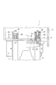
図1に示されるように、本実施形態のレーザ加工ヘッド1は、レーザ加工装置(図示せず)に装着される。このため、レーザ加工ヘッド1は、レーザ加工装置への取付部としてのキャリッジ3を備えている。レーザ加工装置によってキャリッジ3がXYZ軸方向に移動されることで、レーザ加工ヘッド1がワークに対してXYZ軸方向に移動される。この移動のための構成には種々の構成があるが、何れもよく知られた構成であるので詳しい説明は省略する。
キャリッジ3は、ベース部材5を一体的に備えている。ベース部材5の下面には、ヘッド7のヘッド本体9の上面が当接されている。より詳細には、ベース部材5の中央には貫通孔11が形成されており、ヘッド本体9に接続された保護チューブ部材13(図2には図示せず)が貫通孔11を貫通している。保護チューブ部材13は、レーザ発振器(図示せず)からヘッド本体9内の集光レンズ(図示せず)へのレーザ光路の一部を保護する。
ベース部材5の下面の貫通孔11の周縁には、環状の係合段部15が形成されている。一方、ヘッド本体9の上面には、係合段部15と係合可能な係合凸部17が形成されている。なお、ヘッド本体9の上面に係合段部15が形成され、ベース部材5の下面に係合凸部17が形成されてもよい。
ベース部材5の下面とヘッド本体9の上面とを当接させ、かつ、係合段部15と係合凸部17とを係合させる機構について説明する。貫通孔11の周囲には複数の挿通孔19が周方向に等間隔に形成されている。また、各挿通孔19には、上下動可能に支持部材21が挿通されており、支持部材21の下端はヘッド本体9に螺着されている。支持部材21は、ヘッド本体9の上面への取り付け、及び、上面からの取り外しを容易に行なえるように、多角形断面を有する支柱として形成されている。なお、支持部材21は、ヘッド本体9の上面への取り付け、及び、上面からの取り外しを容易に行なえるように、その一部に工具係合用の平面部が形成された支柱として形成されても良い。前記支持部材21の軸心部には軸貫通孔23が形成されている。
支持部材21の軸貫通孔23には、支持部材21の外径よりも小さい外径を有するシャー部材25の下端が螺着されている。シャー部材25は、例えば、市販の小径ネジ(小径のネジ部材)であり、容易に入手できる。シャー部材25の上部にはスプリング座としてフランジ部材27が設けられている。また、フランジ部材27と支持部材21の上面との間には、シャー部材25を囲むパイプ部材29が設けられている。さらに、フランジ部材27とベース部材5との間にはコイルスプリング等の弾性部材31が圧縮状態で取り付けられている。
上述した機構によって、ヘッド7(ヘッド本体9)は、弾性部材31によって上方に付勢され、ヘッド本体9の上面とベース部材5の下面とは当接される。また、ベース部材5の下面中央に係合段部15が形成され、かつ、ヘッド本体9の上面中央に係合凸部17が形成されているので、係合段部15と係合凸部17とが係合され、キャリッジ3(ベース部材5)に対してヘッド7が容易に位置決めされる。
キャリッジ3を介してヘッド7が移動されたときに、ヘッド本体9の下部のノズル等が障害物(ワークW等)と接触すると、接触側の弾性部材31が圧縮されてヘッド本体9が揺動する。障害物との接触が直ぐ終了すれば、弾性部材31の弾性復元力によってヘッド本体9は元の位置に復帰する。この時も、ベース部材5の下面中央に係合段部15が形成され、かつ、ヘッド本体9の上面中央に係合凸部17が形成されているので、係合段部15と係合凸部17との係合によって、キャリッジ3(ベース部材5)に対してヘッド7が容易に元の位置に復帰される。
しかし、障害物との接触によるヘッド本体9の揺動が大きい場合は、図3(B)に示されるように、シャー部材25が破断してヘッド本体9がさらに揺動する。シャー部材25が破断される程度までヘッド本体9が揺動すると、その揺動がセンサなどの揺動検出手段(図示せず)によって検出される。揺動検出手段によってシャー部材25が破断される程度のヘッド本体9の揺動(即ち、シャー部材25の破断)が検出されると、キャリッジ3を介したヘッド7(ヘッド本体9)の移動が停止される。
シャー部材25の外径は支持部材21の外径よりも小さく、かつ、シャー部材25の下端は支持部材21に螺着されているので、支持部材21とシャー部材25との接合部は段差を形成しており応力が集中しやすい。シャー部材25が、支持部材25の上部に螺着されている構造も、上記接合部に応力を集中させやすくしている。このため、シャー部材25は上記接合部で破断されやすい。また、シャー部材25はネジ部材(市販の小径ネジ)であるので、ネジ溝の形成開始部分に応力が集中しやすい。この点からも、シャー部材25は接合部(ネジ溝の形成開始部分)で破断されやすい。従って、所定の外力が作用したときに破断しやすいシャー部材25は容易に入手できる。
シャー部材25が破断したときには、障害物を除去し、かつ、新しいシャー部材25へと交換した後に、レーザ加工ヘッド1によるワークWの切断が再開される。なお、破断したシャー部材25のネジ部分が軸貫通孔23内に残っている場合には、支持部材21をヘッド本体9から取り外し、軸貫通孔23の下端から工具を挿入する。そして、工具先端を残っているネジ部分の下端に押圧当接させ、摩擦力によって残っているネジ部分を回転させて支持部材21から取り外すことができる。
上述したように、シャー部材25は市販の小径ネジであるので、一定強度のシャー部材25(所定値以上の外力が作用したときに破断するシャー部材25)を容易に入手できる。また、支持部材21とフランジ部材27との間に、シャー部材25を囲むパイプ部材29が設けられているので、ベース部材5とフランジ部材27との間隔を一定に保持できる。従って、複数の弾性部材31の付勢力をほぼ一定に保持することができ、ワークWとヘッド本体9との接触方向にかかわりなく、一定の外力に対してシャー部材25を破断させてヘッド本体9を揺動させることができる。
本発明は、上述した実施形態に限定されない。例えば、上記実施形態では、ベース部材5の下面中央に係合段部15が形成され、かつ、ヘッド本体9の上面中央に係合凸部17が形成された。しかし、ベース部材5の下面中央に係合凸部が形成され、かつ、ヘッド本体9の上面中央に係合段部が形成されてもよい。
Claims (5)
- レーザ加工ヘッドであって、
ベース部材を有する、移動可能なキャリッジと、
前記ベース部材の下面と当接される上面を有するヘッド本体と、
前記ベース部材に形成された複数の挿通孔と、
前記複数の挿通孔にそれぞれ挿通され、前記ヘッド本体の上面に下端が取り付けられた複数の支持部材と、
前記複数の支持部材の上部にそれぞれ取り付けられた、前記支持部材の外径よりも小さい外径を有する複数のシャー部材と、
前記複数のシャー部材の上部と前記ベース部材との間にそれぞれ設けられた複数の弾性部材と備えた、レーザ加工ヘッド。 - 請求項1に記載のレーザ加工ヘッドであって、
前記複数の支持部材の中心軸部には、それぞれ軸貫通孔が形成されており、
前記複数のシャー部材は、上記複数の軸貫通孔の上部に螺着されている、レーザ加工ヘッド。 - 請求項1又は2に記載のレーザ加工ヘッドであって、
前記複数のシャー部材の上部にそれぞれ設けられた複数のフランジ部材をさらに備えており、
前記複数のフランジ部材と前記複数の支持部材との間に、前記複数のシャー部材を囲むパイプ部材がそれぞれ設けられている、レーザ加工ヘッド。 - 請求項1~3の何れか一項に記載のレーザ加工ヘッドであって、
前記ベース部材の下面中央に、係合段部及び係合凸部の一方が形成され、前記ヘッド本体の上面中央に前記係合段部及び前記係合凸部の他方が形成されている、レーザ加工ヘッド。 - 請求項1~4の何れか一項に記載のレーザ加工ヘッドであって、
前記シャー部材が、ネジ部材である、レーザ加工ヘッド。
Priority Applications (1)
| Application Number | Priority Date | Filing Date | Title |
|---|---|---|---|
| CN201480032073.7A CN105263666B (zh) | 2013-06-07 | 2014-05-30 | 激光加工头 |
Applications Claiming Priority (2)
| Application Number | Priority Date | Filing Date | Title |
|---|---|---|---|
| JP2013-120354 | 2013-06-07 | ||
| JP2013120354A JP6035206B2 (ja) | 2013-06-07 | 2013-06-07 | レーザ加工ヘッド装置 |
Publications (1)
| Publication Number | Publication Date |
|---|---|
| WO2014196478A1 true WO2014196478A1 (ja) | 2014-12-11 |
Family
ID=52008122
Family Applications (1)
| Application Number | Title | Priority Date | Filing Date |
|---|---|---|---|
| PCT/JP2014/064485 Ceased WO2014196478A1 (ja) | 2013-06-07 | 2014-05-30 | レーザ加工ヘッド |
Country Status (3)
| Country | Link |
|---|---|
| JP (1) | JP6035206B2 (ja) |
| CN (1) | CN105263666B (ja) |
| WO (1) | WO2014196478A1 (ja) |
Cited By (1)
| Publication number | Priority date | Publication date | Assignee | Title |
|---|---|---|---|---|
| EP3130426A1 (de) * | 2015-08-13 | 2017-02-15 | TRUMPF Werkzeugmaschinen GmbH + Co. KG | Werkzeugmaschine mit einer stanzvorrichtung und einer laserbearbeitungsvorrichtung |
Families Citing this family (1)
| Publication number | Priority date | Publication date | Assignee | Title |
|---|---|---|---|---|
| JP7595097B2 (ja) | 2023-01-16 | 2024-12-05 | 株式会社アマダ | 過負荷保護装置及びレーザ加工装置 |
Citations (2)
| Publication number | Priority date | Publication date | Assignee | Title |
|---|---|---|---|---|
| JPH07178546A (ja) * | 1993-12-22 | 1995-07-18 | Koike Sanso Kogyo Co Ltd | トーチ保持構造 |
| US20120168413A1 (en) * | 2009-09-10 | 2012-07-05 | Fronius International Gmbh | Collision protection device |
Family Cites Families (4)
| Publication number | Priority date | Publication date | Assignee | Title |
|---|---|---|---|---|
| JP2659627B2 (ja) * | 1991-05-29 | 1997-09-30 | 株式会社アマダメトレックス | トーチ保護装置 |
| JPH0565490U (ja) * | 1992-02-07 | 1993-08-31 | ヤマザキマザック株式会社 | レーザ加工ヘッド |
| CN201350546Y (zh) * | 2009-02-17 | 2009-11-25 | 武汉奥华光电器件有限公司 | 悬臂移动式激光机 |
| DE202010008855U1 (de) * | 2010-10-21 | 2010-12-30 | Trumpf Werkzeugmaschinen Gmbh + Co. Kg | Bewegungseinheit für einen Bearbeitungskopf einer Werkzeugmaschine |
-
2013
- 2013-06-07 JP JP2013120354A patent/JP6035206B2/ja active Active
-
2014
- 2014-05-30 WO PCT/JP2014/064485 patent/WO2014196478A1/ja not_active Ceased
- 2014-05-30 CN CN201480032073.7A patent/CN105263666B/zh active Active
Patent Citations (2)
| Publication number | Priority date | Publication date | Assignee | Title |
|---|---|---|---|---|
| JPH07178546A (ja) * | 1993-12-22 | 1995-07-18 | Koike Sanso Kogyo Co Ltd | トーチ保持構造 |
| US20120168413A1 (en) * | 2009-09-10 | 2012-07-05 | Fronius International Gmbh | Collision protection device |
Cited By (4)
| Publication number | Priority date | Publication date | Assignee | Title |
|---|---|---|---|---|
| EP3130426A1 (de) * | 2015-08-13 | 2017-02-15 | TRUMPF Werkzeugmaschinen GmbH + Co. KG | Werkzeugmaschine mit einer stanzvorrichtung und einer laserbearbeitungsvorrichtung |
| CN106563947A (zh) * | 2015-08-13 | 2017-04-19 | 通快机床两合公司 | 包括冲压装置和激光加工装置的机床 |
| US10010972B2 (en) | 2015-08-13 | 2018-07-03 | Trumpf Werkzeugmaschinen Gmbh + Co. Kg | Machine tool comprising a punching device and a laser machining device |
| CN106563947B (zh) * | 2015-08-13 | 2020-02-18 | 通快机床两合公司 | 包括冲压装置和激光加工装置的机床 |
Also Published As
| Publication number | Publication date |
|---|---|
| CN105263666A (zh) | 2016-01-20 |
| JP2014237149A (ja) | 2014-12-18 |
| JP6035206B2 (ja) | 2016-11-30 |
| CN105263666B (zh) | 2016-11-23 |
Similar Documents
| Publication | Publication Date | Title |
|---|---|---|
| JP6041189B2 (ja) | スナップリングの装着冶具 | |
| KR101594423B1 (ko) | 레이저 용접용 다목적 지그 장치 | |
| US6797917B1 (en) | Laser machining head | |
| JP5451454B2 (ja) | レーザ加工機 | |
| CN105263666B (zh) | 激光加工头 | |
| KR101099644B1 (ko) | 분리형 마그넷 안전장치를 구비한 로봇 | |
| KR20150037433A (ko) | 쿨런트 노즐장치 | |
| US9358641B2 (en) | Laser machining device | |
| CN108136601A (zh) | 用于机器人校准的剪断销 | |
| JPH07178546A (ja) | トーチ保持構造 | |
| KR101142543B1 (ko) | 레이저 가공헤드의 충격 감지장치 | |
| JP6608867B2 (ja) | ねじ部材供給装置のねじ部材取出機構 | |
| JP2005066682A (ja) | 電極チップ脱却治具及びこれを使用した電極チップ脱却方法 | |
| JP7245056B2 (ja) | 加工ヘッド装置 | |
| KR102230524B1 (ko) | 드릴천공 중앙잔재물 배출이 용이한 다이아몬드세그먼트를 구비하는 코어드릴 | |
| KR101569085B1 (ko) | 탭 척 | |
| JP2011088159A (ja) | レーザ加工機の加工ヘッド | |
| JPH04104271U (ja) | 熱切断機用ト−チの破損防止装置 | |
| JP5917382B2 (ja) | 多関節型ロボットによる精密嵌め合い作業方法およびその作業方法に用いられる多関節型ロボット用ハンド | |
| KR20130035441A (ko) | 체인 핀 보정 지그 | |
| JP7105678B2 (ja) | 連結装置、加工装置、および連結装置の組立方法 | |
| JP2017064825A (ja) | シール部材の組付方法及びシール部材の組付装置 | |
| JP4534687B2 (ja) | 工具クランプ機構、工作機械 | |
| CN105546018A (zh) | 防尘罩的制造工具及防尘罩的制造方法 | |
| RU2516202C2 (ru) | Быстрозажимной цанговый патрон |
Legal Events
| Date | Code | Title | Description |
|---|---|---|---|
| WWE | Wipo information: entry into national phase |
Ref document number: 201480032073.7 Country of ref document: CN |
|
| 121 | Ep: the epo has been informed by wipo that ep was designated in this application |
Ref document number: 14807144 Country of ref document: EP Kind code of ref document: A1 |
|
| NENP | Non-entry into the national phase |
Ref country code: DE |
|
| 122 | Ep: pct application non-entry in european phase |
Ref document number: 14807144 Country of ref document: EP Kind code of ref document: A1 |