WO2014192980A1 - 液体適用装置及び液体適用方法 - Google Patents
液体適用装置及び液体適用方法 Download PDFInfo
- Publication number
- WO2014192980A1 WO2014192980A1 PCT/JP2014/067407 JP2014067407W WO2014192980A1 WO 2014192980 A1 WO2014192980 A1 WO 2014192980A1 JP 2014067407 W JP2014067407 W JP 2014067407W WO 2014192980 A1 WO2014192980 A1 WO 2014192980A1
- Authority
- WO
- WIPO (PCT)
- Prior art keywords
- suction
- web
- liquid
- liquid application
- drum
- Prior art date
- Legal status (The legal status is an assumption and is not a legal conclusion. Google has not performed a legal analysis and makes no representation as to the accuracy of the status listed.)
- Ceased
Links
Images


Classifications
-
- A—HUMAN NECESSITIES
- A61—MEDICAL OR VETERINARY SCIENCE; HYGIENE
- A61F—FILTERS IMPLANTABLE INTO BLOOD VESSELS; PROSTHESES; DEVICES PROVIDING PATENCY TO, OR PREVENTING COLLAPSING OF, TUBULAR STRUCTURES OF THE BODY, e.g. STENTS; ORTHOPAEDIC, NURSING OR CONTRACEPTIVE DEVICES; FOMENTATION; TREATMENT OR PROTECTION OF EYES OR EARS; BANDAGES, DRESSINGS OR ABSORBENT PADS; FIRST-AID KITS
- A61F13/00—Bandages or dressings; Absorbent pads
- A61F13/15—Absorbent pads, e.g. sanitary towels, swabs or tampons for external or internal application to the body; Supporting or fastening means therefor; Tampon applicators
- A61F13/15577—Apparatus or processes for manufacturing
-
- A—HUMAN NECESSITIES
- A61—MEDICAL OR VETERINARY SCIENCE; HYGIENE
- A61F—FILTERS IMPLANTABLE INTO BLOOD VESSELS; PROSTHESES; DEVICES PROVIDING PATENCY TO, OR PREVENTING COLLAPSING OF, TUBULAR STRUCTURES OF THE BODY, e.g. STENTS; ORTHOPAEDIC, NURSING OR CONTRACEPTIVE DEVICES; FOMENTATION; TREATMENT OR PROTECTION OF EYES OR EARS; BANDAGES, DRESSINGS OR ABSORBENT PADS; FIRST-AID KITS
- A61F13/00—Bandages or dressings; Absorbent pads
- A61F13/15—Absorbent pads, e.g. sanitary towels, swabs or tampons for external or internal application to the body; Supporting or fastening means therefor; Tampon applicators
- A61F13/84—Accessories, not otherwise provided for, for absorbent pads
- A61F13/8405—Additives, e.g. for odour, disinfectant or pH control
Definitions
- the present invention relates to a liquid application apparatus and a liquid application method for applying a liquid to a web being conveyed.
- the absorbent article in order to improve the feel and texture of absorbent articles such as paper diapers and sanitary napkins, is composed of a low-viscosity liquid such as a lotion, a softener, and a water-soluble antibacterial agent.
- a method of applying to a sheet is disclosed.
- Patent Document 2 discloses a method for manufacturing an absorbent article in which an absorbent article in which a liquid (skin care agent) is applied to a web (component sheet) being conveyed is continuously manufactured.
- the web may be wrinkled or slack due to its elasticity during transportation, and as a result, the web may meander. Moreover, the liquid applied to the web may not be sufficiently impregnated in the thickness direction of the web.
- Patent Documents 1 and 2 do not mention this at all.
- an object of the present invention is to sufficiently impregnate the inside of the web with a low-viscosity liquid applied to the web while reducing the occurrence of web wrinkles and sagging during web conveyance and suppressing web meandering. Another object is to provide a liquid application apparatus and a liquid application method.
- a liquid application apparatus for applying a liquid having a viscosity in a range of 0.05 to 4 Pa ⁇ s to a continuously conveyed web used for manufacturing an absorbent article, A tank containing the liquid; A liquid application nozzle for applying the liquid to one side of the web; A pump for supplying the liquid in the tank to the liquid application nozzle via a tube; A suction device having a surface facing the other side of the web; With The surface of the suction device includes at least a suction area for sucking the web; A liquid application device is provided.
- a liquid application method for applying a liquid having a viscosity in a range of 0.05 to 4 Pa ⁇ s to a continuously conveyed web used for manufacturing an absorbent article A tank containing the liquid; A liquid application nozzle for applying the liquid to one side of the web; A pump for supplying the liquid in the tank to the liquid application nozzle via a tube; A suction device having a surface facing the other side of the web; And having The surface of the suction device includes at least a suction area for sucking the web; Preparing a liquid application device; Sucking the web in the suction area by the suction device; Applying a liquid to the web; including, A liquid application method is provided.
- the inside of the web is sufficiently impregnated with the low-viscosity liquid applied to the web while suppressing the occurrence of web wrinkles and sagging to suppress the meandering of the web.
- a liquid application apparatus and a liquid application method are provided.
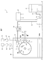
- FIG. 1 is a schematic view of a liquid application apparatus according to a first embodiment of the present invention.
- FIG. 3 is a sectional view taken along line III-III in FIG. 2.
- the diagram which shows the outer periphery of the suction drum of the liquid application apparatus which concerns on 1st embodiment of this invention, an inlet roll, and an outlet roll.
- the partial cross-sectional schematic of the liquid application apparatus which concerns on 2nd embodiment of this invention.
- FIG. 6 is a partial cross-sectional schematic view of a liquid application apparatus according to a modification of the second embodiment of the present invention, similar to FIG. 5.
- FIG. 1 is a schematic view of a liquid application apparatus 1 according to the first embodiment of the present invention.
- the liquid application apparatus 1 applies a low-viscosity liquid to one surface 3ff of the web 3 being conveyed.
- the web 3 is composed of a bonded sheet in which an absorbent body is bonded to a top sheet of a disposable diaper or a sanitary napkin with a certain interval in the conveying direction MD.
- the web 3 is a product, semi-finished product or material of an absorbent article.
- Absorbent articles include paper diapers and sanitary napkins.
- the liquid application apparatus 1 includes a suction drum 5 (corresponding to a suction apparatus).
- the suction drum 5 has a surface 5 f that faces the other surface 3 fs of the web 3.
- the web 3 is sucked by the surface 5 f of the suction drum 5, and the liquid is applied on the surface 5 f of the suction drum 5.
- the structure and operation of the suction drum 5 will be described in detail later.
- the liquid application apparatus 1 further includes an inlet roll 7a and an outlet roll 7b, which are, for example, free rolls having no drive source.
- the web 3 is guided to the suction drum 5 by the inlet roll 7a, specifically, on the surface 5f of the suction drum 5, and is guided to the subsequent process by the outlet roll 7b.
- the liquid application apparatus 1 includes a tank 11 that stores a liquid and a nozzle 13 (corresponding to a liquid application nozzle) that applies the liquid to the sheet 3.
- the liquid application apparatus 1 further includes a pump 17 that supplies the liquid stored in the tank 11 to the nozzle 13 via the tube 15.
- the supply amount of the pump 17 can be changed.
- the tank 11 is disposed at a position higher than the pump 17. As a result, the liquid in the tank 11 reaches the pump 17 by its own weight.
- a filter 19 for removing impurities mixed in the liquid is disposed in the tube 15 between the tank 11 and the pump 17.
- a liquid meter 21 is disposed in the portion of the tube 15 between the pump 17 and the nozzle 13.
- the liquid meter 21 detects the amount of liquid flowing through the tube 15, that is, the amount of liquid actually applied to the sheet 3. Therefore, the amount of liquid actually applied to the sheet 3 can be easily detected.
- the amount of liquid supplied from the liquid application apparatus 1 to the sheet 3 is considerably small, and is about 10 ml / min. Therefore, the liquid meter 21 used in the first embodiment is a Coriolis flow meter.
- the Coriolis flow meter is suitable for measuring such a small amount of liquid.
- the liquid meter 21 is in other forms.
- the Coriolis flow meter is a flow meter that uses the principle of Coriolis force. That is, for example, when a tube is vibrated while a liquid to be measured is circulated in a U-shaped or linear tube, the tube is distorted. The magnitude of this strain depends on the flow rate of liquid flowing through the tube. Accordingly, the liquid flow rate can be detected by detecting the magnitude of the tube distortion.
- the nozzle 13 includes a liquid ejection path (not shown), a pneumatically driven nozzle valve (not shown) that opens or closes the liquid ejection path, and an air chamber (not shown). Prepare inside. That is, when air pressure is applied to the air chamber of the nozzle 13, the nozzle valve is opened and the liquid is ejected from the liquid flow path. On the other hand, when the application of air pressure to the air chamber is stopped, the nozzle valve is closed and the ejection of liquid is stopped.
- the liquid application apparatus 1 further includes a first compressor 23.
- the air chamber of the nozzle 13 and the first compressor 23 are connected via a first air tube 25.
- a nozzle valve opening / closing electromagnetic valve 27 is disposed in a first air tube 25 between the nozzle 13 and the first compressor 23.
- the nozzle 13 includes an air flow passage (not shown) in communication with or adjacent to the liquid flow passage.
- the liquid application apparatus 1 further includes a second compressor 29.
- the air flow passage of the nozzle 13 is connected to the second compressor 29 via the second air tube 31.
- Another electromagnetic valve 33 and a regulator 35 for adjusting the air pressure in the second air tube 31 are attached to the second air tube 31.
- the electromagnetic valve 33 When the electromagnetic valve 33 is opened, compressed air is ejected from the air flow passage, and thus the liquid ejected from the liquid flow passage through the outlet 13o is atomized and applied to the sheet 3.
- the electromagnetic valve 33 is closed, the supply of compressed air to the air flow passage is stopped.
- liquid is ejected from the nozzle 13 without using compressed air.
- the liquid is applied to the web 3 by, for example, a brush or a roller.
- the nozzle 13 is provided with one air outlet 13o, and the air outlet 13o is directed to the center of the suction drum 5 and thus perpendicular to the one surface 3ff of the web 3. Yes.
- the liquid ejected from the blower outlet 13o spreads, for example, in a conical shape having the blower outlet 13o as a vertex, and is applied to one surface 3ff of the web 3 with a certain area.
- the application range of the web width direction CD (FIG. 3) orthogonal to the conveyance direction MD, The distance between one surface 3ff of the web 3 is changed.
- the application time of the liquid is lengthened.
- the nozzle is provided with a plurality of outlets aligned in the width direction CD (FIG. 3) of the web 3 in order to increase the application range of the liquid in the width direction CD (FIG. 3) of the web. ing.
- the application range of the liquid in the web width direction CD (FIG. 3) can be changed without changing the distance of the nozzle 13 from the surface 5f of the suction drum 5.
- the liquid has a viscosity in the range of 0.05 to 4 Pa ⁇ s at least when applied to the sheet 3.
- the liquid has a viscosity in the range of 0.05 to 4 Pa ⁇ s at 20 to 25 ° C. and 1 atm.
- the liquid is a liquid having a higher viscosity.
- the liquid is a liquid having a lower viscosity.
- the liquid is, for example, petroleum hydrocarbon, animal or vegetable oil or fat, animal or vegetable wax, fatty acid ester compound, alkyl ethoxylate, fatty acid ester ethoxylate, fatty alcohol, polysiloxane, or the like.
- the liquid is a pH adjusting agent, an antibacterial agent, a fragrance, a fragrance or the like.
- the liquid is transferred from the liquid application apparatus 1 to the web 3.
- the web is a combined sheet of the top sheet and the absorbent body of the disposable diaper, and corresponds to the longitudinal central portion of the disposable diaper.
- the liquid is intermittently applied to another part of the disposable diaper, or any part of another absorbent article.
- the liquid is applied to the web 3 continuously from the liquid application device 1 in the transport direction MD.
- the liquid application apparatus 1 further includes a controller 37.
- the controller 37 includes a computer having a CPU (microprocessor), a memory, an input port, and an output port.
- a liquid meter 21 or the like is connected to the input port of the controller 37.
- the output port of the controller 37 is connected to the pump 17 and the solenoid valve 27 for opening / closing the nozzle valve.
- the pump 17 and the electromagnetic valve 27 are controlled based on a signal from the controller 37.
- the web 3 conveying operation is controlled by the controller 37, and intermittent injection of the liquid by the nozzle 13, specifically, the timing of opening and closing the solenoid valve 27 for opening and closing the nozzle valve. Is synchronized with. As a result, the liquid can be applied to a desired portion of the one surface 3ff of the web 3.
- FIG. 2 is an enlarged view of FIG. 1 around the suction drum 5, and FIG. 3 is a cross-sectional view taken along line III-III of FIG.
- the suction drum 5 includes a rotating portion 5r that rotates together with the drum shaft 5ds, and a non-rotating non-rotating portion 5s that is positioned inside the suction drum 5, and these are made of a hard material such as metal.
- Each of the rotating portion 5r and the non-rotating portion 5s extends continuously in the rotation direction of the suction drum 5.
- One end (not shown) of the drum shaft 5ds is connected to a rotational drive device (not shown), which is a motor, for example, and the rotational portion 5r of the suction drum 5 can be rotationally driven by the driving force.
- the radial direction RD refers to a direction perpendicular to the extending direction of the drum shaft 5 ds.
- the rotating portion 5r includes a side surface portion 5rs, an outer peripheral base portion 5rc, and a mesh portion 5rm.
- the side surface portion 5rs that constitutes one side surface of the suction drum 5 is connected to the other end 5dse of the drum shaft 5ds by connecting means such as a bolt.
- the outer periphery base part 5rc which comprises the outer peripheral part of the suction drum 5 with the mesh part 5rm is connected with the radial direction outermost part of the side part 5rs by the connection means which is a volt
- the mesh portion 5rm is formed by stacking a plurality of mesh-like sheets that are nets made of, for example, a metal or a resin material.
- the non-rotating part 5s includes a hollow shaft 5ss and a side wall 5sw.
- the hollow shaft 5ss has a drum shaft 5ds inserted substantially coaxially in the hollow portion.
- a bearing 5br is provided between the outer peripheral surface of the drum shaft 5ds and the inner peripheral surface of the hollow shaft 5ss.
- the hollow shaft 5ss is fixed to, for example, an equipment wall (not shown) so as not to rotate and to support the load of the entire suction drum 5.
- the hollow shaft 5ss is connected at its outer peripheral surface to a side wall 5sw extending in the radial direction RD of the suction drum 5 between the outer surface of the hollow shaft 5ss and the inner surface of the outer peripheral base portion 5rc by a connecting means such as a bolt.
- a ring-shaped body 5sr made of felt, for example, is attached to the radially outermost part of the side wall 5sw. Since the ring-shaped body 5sr continuously extends in the rotation direction of the suction drum 5, the ring-shaped body 5sr has a ring shape.
- the ring-shaped body 5sr reduces the sliding resistance between the rotating outer peripheral base 5rc and the non-rotating side wall 5sw while ensuring a certain hermeticity.
- the material of the ring-shaped body 5sr is not limited to felt as long as it exhibits the above function, and may be another material.
- the suction drum 5 has a hollow portion 5h defined by the hollow shaft 5ss, the side wall 5sw, the ring-shaped body 5sr, and the outer peripheral base 5rc.
- the side wall 5sw of the suction drum 5 is provided with an exhaust hole 5swv, and one end of the duct 41 is connected to the suction drum 5 in the exhaust hole 5swv.
- the inside of the duct 41 communicates with the hollow portion 5h.
- the other end of the duct 41 is connected to an exhaust pump (not shown) that discharges air inside the hollow portion 5h in the direction F.
- one duct 41 and one exhaust pump are used.
- a plurality of exhaust holes 5swv are provided in the side wall 5sw, and the plurality of exhaust pumps are respectively connected to the suction drum 5 via the duct 41. By connecting, the amount of suction can be increased.
- the outer peripheral base 5rc is provided with a number of through holes 5rcp penetrating from the outer peripheral surface of the outer peripheral base 5rc to the inner peripheral surface.
- the through holes 5rcp are provided so as to be distributed substantially uniformly on the surface of the outer peripheral base portion 5rc.
- FIG. 3 the through holes 5 rcp provided on the inner surface of the outer peripheral base portion 5 rc are shown, but from the viewpoint of easy viewing, only a part of them is shown in the drawing.
- seat as mentioned above can let air pass. Therefore, the hollow portion 5 h communicates with the outside of the suction drum 5.
- the exhaust pump (not shown) discharges air from the hollow portion 5h, while the hollow portion 5h includes the web 3 positioned on the mesh portion 5rm and the mesh portion 5rm from the outside of the suction drum 5. Then, air is introduced through the through hole 5rcp of the outer peripheral base 5rc.
- the surface 5f of the suction drum 5 that faces the other surface 3fs of the web 3 is the outer surface of the mesh portion 5rm.
- the suction drum 5 is provided with a partition 43 in contact with a part of the inner surface of the outer peripheral base portion 5rc inside the hollow portion 5h.
- the partition 43 is attached to the hollow shaft 5ss or the side wall 5sw by a jig (not shown).
- the contact portion between the partition 43 and the inner surface of the outer peripheral base portion 5rc is made of felt, for example, for the same purpose as the ring-shaped body 5sr.
- the partition 43 prevents the intake air from the outside of the suction drum 5 through the through hole 5rcp of the outer peripheral base portion 5rc at the contact portion.
- the surface 5f of the suction drum 5 is a length area along the outer periphery of the suction drum 5, and a suction area AS for sucking the web 3, and the web 3 and a non-suction area AN that does not suck 3.
- the suction drum 5 is not provided with the partition 43, and the surface 5f of the suction drum 5 is the suction area AS that sucks the web 3 all around, and thus does not include the non-suction area AN. .
- the suction drum 5 sucks the web 3 in the suction area AS included in the surface 5f facing the other surface 3fs opposite to the one surface 3ff to which the liquid is applied.
- the through holes 5rcp are provided so as to be distributed substantially uniformly on the surface of the outer peripheral base portion 5rc.
- the mesh part 5rm of the above-mentioned structure is provided in the outer surface of the suction drum 5, the path
- the web 3 is attracted to the surface 5 f and held by being sucked by the suction drum 5.
- the web 3 is conveyed along with the rotation of the suction drum 5, and is conveyed by the suction drum 5 in the liquid application apparatus 1 of the first embodiment.
- liquid application apparatus 1 of the first embodiment According to the liquid application apparatus 1 of the first embodiment, the following operational effects can be achieved.
- the portion of the web 3 located in the suction region AS of the surface 5f of the suction drum 5 is held on the surface 5f by being sucked with a substantially uniform suction force as a whole. Be transported. As a result, when the web 3 is transported, the occurrence of wrinkles and sagging of the web 3 is reduced, and consequently, the meandering of the web 3 can be suppressed.
- the liquid applied to the one surface 3ff of the web 3 By sucking the liquid applied to the one surface 3ff of the web 3 from the other surface 3fs of the web 3, the liquid is moved from the one surface 3ff side to the other surface 3fs side inside the web 3. be able to. As a result, the liquid applied to the web 3 can be sufficiently impregnated inside the web 3. In addition, in order to fully exhibit this effect, it is preferable that the air permeability of the web 3 is high.
- the web 3 according to the first embodiment is a combined sheet of a top sheet and an absorbent body, and generally does not include a material having low air permeability such as a plastic film included in a back sheet of an absorbent article. Therefore, the air permeability of the web 3 is high and preferable.
- the suction area AS of the surface 5 f of the suction drum 5 is a length area along the outer periphery of the suction drum 5 corresponding to at least the application range of the liquid by the nozzle 13 to the web 3.
- the liquid application area AA is preferably included. This is because in the suction area AS on the surface 5f of the suction drum 5, it is difficult for wrinkles and sagging to occur on the web 3, so that the liquid can be appropriately applied to a desired range of the one surface 3ff of the web 3.
- the suction area AS does not include the liquid application area AA.
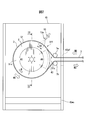
- FIG. 4 is a diagram showing the outer periphery of the suction drum 5, the inlet roll 7a and the outlet roll 7b of the liquid application apparatus according to the first embodiment of the present invention. 4 is a view of the suction drum 5, the inlet roll 7a, and the outlet roll 7b when viewed in the direction in which the drum shaft 5ds of the suction drum 5 extends.
- the contact point between the outer circumference of the suction drum 5 and the inlet roll 7a and the outer circumference of the suction drum 5 is a first point P1, and the common tangent L2 of the outer circumference of the suction drum 5 and the outlet roll 7b.
- the outer periphery of the suction drum 5 is defined as a second point P2.
- the surface 5f of the suction drum 5 is a length along the surface 5f of the suction drum 5 from the first point P1 to the second point P2 along the outer periphery in the direction opposite to the rotation direction R of the suction drum 5.
- the area APP preferably includes a non-suction area AN (FIG. 2) that prevents the web 3 from being suctioned.
- the area APP does not include the non-suction area AN (FIG. 2).
- the range of the non-suction area AN (FIG. 2) is defined by the size and position of the partition 43 in the circumferential direction of the suction drum 5.
- the liquid application apparatus 1 preferably further includes a cover 45 in which the suction drum 5 and the nozzle 13 are accommodated. This is because it is possible to prevent the liquid ejected from the nozzle 13 from being scattered to the surroundings, and further, it is possible to prevent dust such as fiber scraps flying from the outside of the liquid application apparatus 1 from adhering to the web 3. .
- the cover 45 has a box shape in which the four sides and the upper side are surrounded. In another embodiment, the liquid application apparatus 1 does not include the cover 45.
- At least one surface of the cover 45 is made of a transparent material so that the inside of the cover 45 can be visually recognized even during use.
- the front surface of the cover 45 is made of a transparent material.
- the cover 45 is provided with a first opening 45 wf for carrying the web 3 in and out of the cover 45.
- the cover 45 is provided with a second opening 45ws positioned vertically below the first opening 45wf.
- the second opening 45ws By providing the second opening 45ws separately from the first opening 45wf, more air can be introduced into the cover, and the intake efficiency from the outside of the suction drum 5 can be improved.
- the second opening 45ws is positioned lower than the first opening 45wf in the vertical direction, dust such as fiber dust that may have risen around the cover 45 is sucked into the cover 45. Can be suppressed.
- a plurality of second openings 45ws may be provided on any surface of the cover 45 as long as the second openings 45ws are vertically lower than the first openings 45wf.
- the second opening 45ws is provided with a filter (not shown) so as not to suck dust such as fiber waste.
- the cover 45 is not provided with the second opening 45ws.
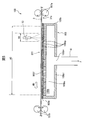
- FIG. 5 is a schematic partial cross-sectional view of the liquid application apparatus 100 according to the second embodiment of the present invention.
- the mechanism for ejecting the liquid from the nozzle 13 is the same as that in FIG.
- the second embodiment is mainly different from the first embodiment in that the web 3 is sucked using a suction box 105 (corresponding to a suction device) instead of the suction drum 5 (FIG. 1 and the like).
- the web 3 is conveyed in the conveying direction MD by the conveying devices 107 a and 107 b on the surface 105 f on the upper side in the vertical direction of the suction box 105.
- the suction box 105 has a rectangular parallelepiped shape as a whole, and includes a main body portion 105b constituting an outer portion of the suction box 105 and a hollow portion 105h positioned inside the main body portion 105b.
- an exhaust hole 105bv is provided in the lower part 105bl of the main body part 105b of the suction box 105, and one end of the duct 41 is connected to the suction box 105 in the exhaust hole 105bv. .
- the inside of the duct 41 communicates with the hollow portion 105h.
- the other end of the duct 41 is connected to an exhaust pump (not shown) that discharges air in the hollow portion 105 h in the direction F.
- a plurality of exhaust holes 105bv are provided in the main body portion 105b, and a plurality of exhaust pumps are connected to the suction box 105 via the ducts 41, respectively. Can be increased.
- the upper portion 105bu of the main body portion 105b is provided with a large number of through holes 105bp.
- the through holes 105bp are provided so as to be distributed substantially uniformly over the entire surface of the upper portion 105bu.
- the mesh part 105m similar to the mesh part 5rm of 1st embodiment is provided in the surface of the vertical direction upper side of the suction box 105.
- seat can let air pass. Therefore, the hollow portion 105 h communicates with the outside of the suction box 105.
- the surface 105f of the suction box 105 facing the other surface 3fs of the web 3 is the outer surface of the mesh portion 105m.
- the surface 105 f of the suction box 105 is a length area of the surface 105 f within the range where the through hole 105 bp is provided, and can suck the web 3.
- the area AS is included.
- the web 3 is different from the first embodiment in that the web 3 slides on the surface 105f of the suction box 105. However, it is conveyed to the suction box 105 while being sucked with a substantially uniform suction force as a whole. As a result, when the web 3 is conveyed, the occurrence of wrinkles and sagging of the web 3 is reduced as in the first embodiment, and consequently, the meandering of the web 3 can be suppressed.
- the suction area AS is at least the length area of the surface 105f of the suction box 105 and includes the liquid application area AA to which the liquid is applied.
- the suction area AS does not include the liquid application area AA.
- FIG. 6 is a partial cross-sectional schematic view of a liquid application apparatus 100 according to a modification of the second embodiment of the present invention, similar to FIG. In this modification, the liquid application apparatus 100 further includes a mesh belt 109.
- the mesh belt 109 is wound around a pair of rollers 109 a and 109 b around the suction box 105.
- the mesh belt 109 is a breathable endless belt formed of a mesh-like sheet, which is a net made of a material such as metal or resin.
- At least one of the pair of rollers 109a and 109b is rotationally driven by a drive source such as a servo motor (not shown) so that the mesh belt 109 moves in the transport direction MD on the surface 105f of the suction box 105.
- a drive source such as a servo motor (not shown) so that the mesh belt 109 moves in the transport direction MD on the surface 105f of the suction box 105.
- an exhaust hole 105bv is provided in one side part 105bs of the main body part 105b, and one end of the duct is formed in the exhaust hole so that the suction belt 109 and the duct (not shown) do not interfere with each other. 105bv. The other end of the duct is connected to an exhaust pump (not shown).
- the liquid application apparatus 100 of the present modification includes an inlet roll 7a and an outlet roll 7b.
- the web 3 is guided on the mesh belt 109 by the inlet roll 7a and guided to the subsequent process by the outlet roll 7b.
- the web 3 positioned on the mesh belt 109 is sucked and held on the outer surface of the mesh belt 109 by being sucked by the suction box 105 in the suction area AS. As a result, the web 3 is conveyed along with the movement of the mesh belt 109, and is conveyed by the mesh belt 109 in the liquid application apparatus 100 of the present modification.
- the portion of the web 3 positioned on the suction area AS of the surface 105f of the suction box 105 is held on the outer surface of the mesh belt 109 by being sucked with a substantially uniform suction force as a whole. It is conveyed while. As a result, the generation of wrinkles and sagging during conveyance is reduced, and consequently the meandering of the web 3 can be suppressed.
- the liquid application apparatus 100 of the second embodiment does not include the cover 45 included in the liquid application apparatus 1 of the first embodiment.
- a modified embodiment in which the liquid application apparatus 100 according to the second embodiment includes the cover 45 that accommodates the nozzle 13 and the suction box 105 therein is also included in the scope of the present invention.
- the present invention is defined as follows.
- a liquid application apparatus for applying a liquid having a viscosity in the range of 0.05 to 4 Pa ⁇ s to a continuously conveyed web used for manufacturing an absorbent article, A tank containing the liquid; A liquid application nozzle for applying the liquid to one side of the web; A pump for supplying the liquid in the tank to the liquid application nozzle via a tube; A suction device having a surface facing the other side of the web; With The surface of the suction device includes at least a suction area for sucking the web; Liquid application equipment.
- the suction region includes at least a liquid application region to which the liquid is applied.
- the liquid application apparatus according to (1).
- the suction device is a suction drum,
- the surface of the suction device is an outer peripheral surface of the suction drum;
- the web is conveyed along with the rotation of the suction drum while being sucked by the suction driven drum.
- the surface of the suction device has a contact point between the outer periphery of the suction drum and the outlet roll as a first point, and the common tangent of the outer periphery of the suction drum and the inlet roll and the outer periphery of the suction drum.
- the contact point with the outer periphery of the suction drum is a second point, the web is placed in a region from the first point to the second point along the outer periphery in the direction opposite to the rotation direction of the suction drum. Including a non-suction area that is made non-suction, The liquid application apparatus according to (3).
- the suction device is a suction box
- the surface of the suction device is a surface on the upper side in the vertical direction of the suction box
- the web is conveyed on the surface of the suction box while being sucked by the suction box.
- the liquid application nozzle and the suction device further include a cover accommodated therein.
- the liquid application apparatus according to any one of (1) to (6).
- the cover includes A first opening for carrying the web into and out of the cover; A second opening located vertically below the first opening; Is provided, The liquid application apparatus according to (7).
- the liquid is intermittently applied to the web.
- the liquid application apparatus according to any one of (1) to (8).
- a liquid application method for applying a liquid having a viscosity in a range of 0.05 to 4 Pa ⁇ s to a continuously conveyed web used for manufacturing an absorbent article A tank containing the liquid; A liquid application nozzle for applying the liquid to one side of the web; A pump for supplying the liquid in the tank to the liquid application nozzle via a tube; A suction device having a surface facing the other side of the web; And having The surface of the suction device includes at least a suction area for sucking the web; Preparing a liquid application device; Sucking the web in the suction area by the suction device; Applying a liquid to the web; including, Liquid application method.
Landscapes
- Health & Medical Sciences (AREA)
- Engineering & Computer Science (AREA)
- Vascular Medicine (AREA)
- Epidemiology (AREA)
- Biomedical Technology (AREA)
- Heart & Thoracic Surgery (AREA)
- Life Sciences & Earth Sciences (AREA)
- Animal Behavior & Ethology (AREA)
- General Health & Medical Sciences (AREA)
- Public Health (AREA)
- Veterinary Medicine (AREA)
- Manufacturing & Machinery (AREA)
- Absorbent Articles And Supports Therefor (AREA)
- Coating Apparatus (AREA)
Priority Applications (3)
| Application Number | Priority Date | Filing Date | Title |
|---|---|---|---|
| KR1020157021781A KR102047580B1 (ko) | 2013-07-22 | 2014-06-30 | 액체 적용 장치 및 액체 적용 방법 |
| CN201480001920.3A CN104487036B (zh) | 2013-07-22 | 2014-06-30 | 液体施加装置及液体施加方法 |
| IN312DEN2015 IN2015DN00312A (https=) | 2013-07-22 | 2014-06-30 |
Applications Claiming Priority (2)
| Application Number | Priority Date | Filing Date | Title |
|---|---|---|---|
| JP2013-151632 | 2013-07-22 | ||
| JP2013151632A JP5748806B2 (ja) | 2013-07-22 | 2013-07-22 | 液体適用装置及び液体適用方法 |
Publications (2)
| Publication Number | Publication Date |
|---|---|
| WO2014192980A1 true WO2014192980A1 (ja) | 2014-12-04 |
| WO2014192980A4 WO2014192980A4 (ja) | 2015-01-15 |
Family
ID=51988989
Family Applications (1)
| Application Number | Title | Priority Date | Filing Date |
|---|---|---|---|
| PCT/JP2014/067407 Ceased WO2014192980A1 (ja) | 2013-07-22 | 2014-06-30 | 液体適用装置及び液体適用方法 |
Country Status (6)
| Country | Link |
|---|---|
| JP (1) | JP5748806B2 (https=) |
| KR (1) | KR102047580B1 (https=) |
| CN (1) | CN104487036B (https=) |
| IN (1) | IN2015DN00312A (https=) |
| TW (1) | TWI638647B (https=) |
| WO (1) | WO2014192980A1 (https=) |
Cited By (1)
| Publication number | Priority date | Publication date | Assignee | Title |
|---|---|---|---|---|
| CN107106349A (zh) * | 2014-12-25 | 2017-08-29 | 尤妮佳股份有限公司 | 吸收性物品的制造方法及吸收性物品的制造装置 |
Families Citing this family (3)
| Publication number | Priority date | Publication date | Assignee | Title |
|---|---|---|---|---|
| JP5748807B2 (ja) * | 2013-07-22 | 2015-07-15 | ユニ・チャーム株式会社 | 液体適用装置及び液体適用方法 |
| WO2020178665A2 (en) * | 2019-03-02 | 2020-09-10 | Lohia Corp Limited | A composite bag and a method of and an apparatus for making it |
| JP2024052297A (ja) * | 2022-09-30 | 2024-04-11 | 花王株式会社 | 機能性複合シートの製造方法 |
Citations (7)
| Publication number | Priority date | Publication date | Assignee | Title |
|---|---|---|---|---|
| US5711994A (en) * | 1995-12-08 | 1998-01-27 | Kimberly-Clark Worldwide, Inc. | Treated nonwoven fabrics |
| JP2000505847A (ja) * | 1996-12-20 | 2000-05-16 | ザ、プロクター、エンド、ギャンブル、カンパニー | 粒子状材料を含むドライレイされた構造体 |
| JP2000303347A (ja) * | 1999-03-22 | 2000-10-31 | Gerold Fleissner | 動水式穿穴加工によって有穴フリース材料を製造する方法と装置 |
| WO2011122355A1 (ja) * | 2010-03-29 | 2011-10-06 | ユニ・チャーム株式会社 | 不織布シート |
| JP2011200633A (ja) * | 2010-03-01 | 2011-10-13 | Kao Corp | 吸収性物品の製造方法 |
| JP2013063385A (ja) * | 2011-09-16 | 2013-04-11 | Kao Corp | 塗布方法及び吸収性物品の製造方法 |
| WO2013150835A1 (ja) * | 2012-04-02 | 2013-10-10 | ユニ・チャーム株式会社 | 適用装置及び適用方法 |
Family Cites Families (10)
| Publication number | Priority date | Publication date | Assignee | Title |
|---|---|---|---|---|
| JP3462232B2 (ja) * | 1993-03-25 | 2003-11-05 | 花王株式会社 | 吸収体の製造方法及び製造装置 |
| US5711991A (en) * | 1995-11-20 | 1998-01-27 | Aluminum Company Of America | Process for making lithographic sheet material having a thermoplastic adhesive layer |
| US7082645B2 (en) | 2002-10-16 | 2006-08-01 | Kimberly-Clark Worldwide, Inc. | Fiber blending apparatus and method |
| JP3992597B2 (ja) | 2002-11-21 | 2007-10-17 | 花王株式会社 | 嵩高不織布の製造方法 |
| US7943813B2 (en) * | 2002-12-30 | 2011-05-17 | Kimberly-Clark Worldwide, Inc. | Absorbent products with enhanced rewet, intake, and stain masking performance |
| JP4025212B2 (ja) | 2003-01-31 | 2007-12-19 | 大王製紙株式会社 | 吸収性物品の製造方法 |
| JP2011143240A (ja) | 2009-12-14 | 2011-07-28 | Kao Corp | 吸収性物品の製造方法 |
| CN102573732B (zh) * | 2009-12-14 | 2016-06-08 | 花王株式会社 | 吸收性物品的制造方法 |
| JP5748807B2 (ja) * | 2013-07-22 | 2015-07-15 | ユニ・チャーム株式会社 | 液体適用装置及び液体適用方法 |
| US9572729B2 (en) | 2013-09-30 | 2017-02-21 | Kimberly-Clark Worldwide, Inc. | Method of forming an absorbent structure |
-
2013
- 2013-07-22 JP JP2013151632A patent/JP5748806B2/ja active Active
-
2014
- 2014-06-30 KR KR1020157021781A patent/KR102047580B1/ko active Active
- 2014-06-30 IN IN312DEN2015 patent/IN2015DN00312A/en unknown
- 2014-06-30 WO PCT/JP2014/067407 patent/WO2014192980A1/ja not_active Ceased
- 2014-06-30 CN CN201480001920.3A patent/CN104487036B/zh active Active
- 2014-07-22 TW TW103125113A patent/TWI638647B/zh active
Patent Citations (7)
| Publication number | Priority date | Publication date | Assignee | Title |
|---|---|---|---|---|
| US5711994A (en) * | 1995-12-08 | 1998-01-27 | Kimberly-Clark Worldwide, Inc. | Treated nonwoven fabrics |
| JP2000505847A (ja) * | 1996-12-20 | 2000-05-16 | ザ、プロクター、エンド、ギャンブル、カンパニー | 粒子状材料を含むドライレイされた構造体 |
| JP2000303347A (ja) * | 1999-03-22 | 2000-10-31 | Gerold Fleissner | 動水式穿穴加工によって有穴フリース材料を製造する方法と装置 |
| JP2011200633A (ja) * | 2010-03-01 | 2011-10-13 | Kao Corp | 吸収性物品の製造方法 |
| WO2011122355A1 (ja) * | 2010-03-29 | 2011-10-06 | ユニ・チャーム株式会社 | 不織布シート |
| JP2013063385A (ja) * | 2011-09-16 | 2013-04-11 | Kao Corp | 塗布方法及び吸収性物品の製造方法 |
| WO2013150835A1 (ja) * | 2012-04-02 | 2013-10-10 | ユニ・チャーム株式会社 | 適用装置及び適用方法 |
Cited By (1)
| Publication number | Priority date | Publication date | Assignee | Title |
|---|---|---|---|---|
| CN107106349A (zh) * | 2014-12-25 | 2017-08-29 | 尤妮佳股份有限公司 | 吸收性物品的制造方法及吸收性物品的制造装置 |
Also Published As
| Publication number | Publication date |
|---|---|
| IN2015DN00312A (https=) | 2015-06-12 |
| JP2015019927A (ja) | 2015-02-02 |
| CN104487036A (zh) | 2015-04-01 |
| KR102047580B1 (ko) | 2019-11-21 |
| TWI638647B (zh) | 2018-10-21 |
| JP5748806B2 (ja) | 2015-07-15 |
| KR20160033647A (ko) | 2016-03-28 |
| TW201529051A (zh) | 2015-08-01 |
| WO2014192980A4 (ja) | 2015-01-15 |
| CN104487036B (zh) | 2016-09-07 |
Similar Documents
| Publication | Publication Date | Title |
|---|---|---|
| JP4542900B2 (ja) | 複数の重ね合わされた繊維層を持つ物品を空気形成する方法及び装置 | |
| JP4905973B2 (ja) | 吸引装置、シートの搬送方法、吸収体の製造方法及び不織布の嵩回復方法 | |
| JP5748806B2 (ja) | 液体適用装置及び液体適用方法 | |
| US9540768B2 (en) | Sheet manufacturing apparatus | |
| EP3396040B1 (en) | Device for manufacturing particulate-containing article and method for manufacturing particulate-containing article | |
| CN105007873B (zh) | 吸收体的制造装置 | |
| TW201134459A (en) | Method and device for manufacturing absorption body | |
| US20090212468A1 (en) | Apparatus and method for forming air-laid absorbent cores | |
| JP5748807B2 (ja) | 液体適用装置及び液体適用方法 | |
| CN102112080B (zh) | 用于制造吸收体的装置及方法 | |
| JP5936663B2 (ja) | 吸収性物品を製造する方法 | |
| CN104411277B (zh) | 吸收体制造装置 | |
| JP5068140B2 (ja) | 粉粒体の撒布方法および装置 | |
| JP3195748U (ja) | 可搬式トウバンド開繊装置及び繊維シート製造装置 | |
| CN102791915A (zh) | 处理层压产品的设备 | |
| JP5296663B2 (ja) | 吸収体の製造方法及び製造装置 | |
| JP2010136880A (ja) | 粉粒体の撒布装置および粉粒体の撒布方法 | |
| JP7296301B2 (ja) | 吸収体の製造方法 | |
| JP4786745B2 (ja) | エアレイド物品を製造する装置 | |
| US20260060847A1 (en) | Method and apparatus for producing a hygienic article | |
| JP2013027588A (ja) | 吸収体の製造装置及び製造方法 | |
| JP4884194B2 (ja) | 吸収体の製造装置及び製造方法 | |
| JP5989053B2 (ja) | 吸収体の製造装置 | |
| JPWO2002002858A1 (ja) | ロール仕上方法、およびロール仕上機 |
Legal Events
| Date | Code | Title | Description |
|---|---|---|---|
| 121 | Ep: the epo has been informed by wipo that ep was designated in this application |
Ref document number: 14804021 Country of ref document: EP Kind code of ref document: A1 |
|
| WWE | Wipo information: entry into national phase |
Ref document number: IDP00201500526 Country of ref document: ID |
|
| ENP | Entry into the national phase |
Ref document number: 20157021781 Country of ref document: KR Kind code of ref document: A |
|
| NENP | Non-entry into the national phase |
Ref country code: DE |
|
| 122 | Ep: pct application non-entry in european phase |
Ref document number: 14804021 Country of ref document: EP Kind code of ref document: A1 |