WO2014192152A1 - Dispositif électronique et programme de commande - Google Patents
Dispositif électronique et programme de commande Download PDFInfo
- Publication number
- WO2014192152A1 WO2014192152A1 PCT/JP2013/065264 JP2013065264W WO2014192152A1 WO 2014192152 A1 WO2014192152 A1 WO 2014192152A1 JP 2013065264 W JP2013065264 W JP 2013065264W WO 2014192152 A1 WO2014192152 A1 WO 2014192152A1
- Authority
- WO
- WIPO (PCT)
- Prior art keywords
- unit
- region
- imaging
- area
- image
- Prior art date
Links
Images


Classifications
-
- H—ELECTRICITY
- H04—ELECTRIC COMMUNICATION TECHNIQUE
- H04N—PICTORIAL COMMUNICATION, e.g. TELEVISION
- H04N23/00—Cameras or camera modules comprising electronic image sensors; Control thereof
- H04N23/60—Control of cameras or camera modules
- H04N23/62—Control of parameters via user interfaces
-
- G—PHYSICS
- G06—COMPUTING; CALCULATING OR COUNTING
- G06T—IMAGE DATA PROCESSING OR GENERATION, IN GENERAL
- G06T7/00—Image analysis
- G06T7/10—Segmentation; Edge detection
- G06T7/11—Region-based segmentation
-
- G—PHYSICS
- G06—COMPUTING; CALCULATING OR COUNTING
- G06T—IMAGE DATA PROCESSING OR GENERATION, IN GENERAL
- G06T7/00—Image analysis
- G06T7/10—Segmentation; Edge detection
- G06T7/194—Segmentation; Edge detection involving foreground-background segmentation
-
- H—ELECTRICITY
- H04—ELECTRIC COMMUNICATION TECHNIQUE
- H04N—PICTORIAL COMMUNICATION, e.g. TELEVISION
- H04N23/00—Cameras or camera modules comprising electronic image sensors; Control thereof
- H04N23/60—Control of cameras or camera modules
- H04N23/63—Control of cameras or camera modules by using electronic viewfinders
- H04N23/631—Graphical user interfaces [GUI] specially adapted for controlling image capture or setting capture parameters
- H04N23/632—Graphical user interfaces [GUI] specially adapted for controlling image capture or setting capture parameters for displaying or modifying preview images prior to image capturing, e.g. variety of image resolutions or capturing parameters
-
- H—ELECTRICITY
- H04—ELECTRIC COMMUNICATION TECHNIQUE
- H04N—PICTORIAL COMMUNICATION, e.g. TELEVISION
- H04N23/00—Cameras or camera modules comprising electronic image sensors; Control thereof
- H04N23/60—Control of cameras or camera modules
- H04N23/63—Control of cameras or camera modules by using electronic viewfinders
- H04N23/633—Control of cameras or camera modules by using electronic viewfinders for displaying additional information relating to control or operation of the camera
-
- H—ELECTRICITY
- H04—ELECTRIC COMMUNICATION TECHNIQUE
- H04N—PICTORIAL COMMUNICATION, e.g. TELEVISION
- H04N25/00—Circuitry of solid-state image sensors [SSIS]; Control thereof
- H04N25/10—Circuitry of solid-state image sensors [SSIS]; Control thereof for transforming different wavelengths into image signals
- H04N25/11—Arrangement of colour filter arrays [CFA]; Filter mosaics
- H04N25/13—Arrangement of colour filter arrays [CFA]; Filter mosaics characterised by the spectral characteristics of the filter elements
- H04N25/134—Arrangement of colour filter arrays [CFA]; Filter mosaics characterised by the spectral characteristics of the filter elements based on three different wavelength filter elements
-
- H—ELECTRICITY
- H04—ELECTRIC COMMUNICATION TECHNIQUE
- H04N—PICTORIAL COMMUNICATION, e.g. TELEVISION
- H04N25/00—Circuitry of solid-state image sensors [SSIS]; Control thereof
- H04N25/50—Control of the SSIS exposure
- H04N25/53—Control of the integration time
- H04N25/533—Control of the integration time by using differing integration times for different sensor regions
-
- H—ELECTRICITY
- H04—ELECTRIC COMMUNICATION TECHNIQUE
- H04N—PICTORIAL COMMUNICATION, e.g. TELEVISION
- H04N25/00—Circuitry of solid-state image sensors [SSIS]; Control thereof
- H04N25/70—SSIS architectures; Circuits associated therewith
- H04N25/76—Addressed sensors, e.g. MOS or CMOS sensors
-
- H—ELECTRICITY
- H04—ELECTRIC COMMUNICATION TECHNIQUE
- H04N—PICTORIAL COMMUNICATION, e.g. TELEVISION
- H04N25/00—Circuitry of solid-state image sensors [SSIS]; Control thereof
- H04N25/70—SSIS architectures; Circuits associated therewith
- H04N25/79—Arrangements of circuitry being divided between different or multiple substrates, chips or circuit boards, e.g. stacked image sensors
-
- G—PHYSICS
- G06—COMPUTING; CALCULATING OR COUNTING
- G06T—IMAGE DATA PROCESSING OR GENERATION, IN GENERAL
- G06T2207/00—Indexing scheme for image analysis or image enhancement
- G06T2207/10—Image acquisition modality
- G06T2207/10004—Still image; Photographic image
Definitions
- the present invention relates to an electronic device and a control program.
- an electronic device including an imaging element in which a backside illumination type imaging chip and a signal processing chip are stacked (hereinafter, this imaging element is referred to as a multilayer imaging element) has been proposed (for example, see Patent Document 1).
- the multilayer imaging element is laminated so that the back-illuminated imaging chip and the signal processing chip are connected via a micro bump for each block unit including a plurality of pixels.
- the change in the image corresponding to the change in the accumulation condition for each area is confirmed in the live view image by making the accumulation condition for the first area and the accumulation condition for the second area different in the live view image.
- the imaging unit has an imaging device and can capture the first region and the second region, and the live corresponding to the first region and the second region captured by the imaging unit.
- an electronic apparatus including a control unit that displays a view image on a display unit, and a changing unit that changes a storage condition for a first region of a live view image and a storage condition for a second region.
- the display unit that has the imaging element and can display the live view image captured by the imaging unit that captures the first region and the second region, and the first image captured by the imaging unit.
- an electronic device including a control unit that displays a menu for setting imaging conditions of a live view image on the display unit when a live view image corresponding to the first region and the second region is displayed on the display unit Is done.
- the first region captured by the image capturing unit and the first region captured by the image capturing unit are included in the control device of the electronic device that includes the image capturing element and includes the image capturing unit capable of capturing the first region and the second region.
- the electronic apparatus control device includes a display unit that includes the imaging element and can display the live view image captured by the imaging unit that captures the first region and the second region.
- First display processing for displaying live view images corresponding to the first region and the second region captured by the imaging unit on the display unit, and imaging conditions for the live view image when the first display processing is performed
- a control program for executing a second display process for displaying a menu for setting the display on the display unit.
- the change in the image corresponding to the change of the storage condition for each region is changed in the live view image. Can be confirmed.
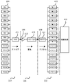
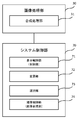
- FIG. 2 is a functional block diagram of an image processing unit and a system control unit in the first embodiment.
- FIG. It is a flowchart for demonstrating the imaging
- FIG. 1 is a cross-sectional view of a multilayer image sensor.
- the multilayer image sensor 100 is described in Japanese Patent Application No. 2012-139026 filed earlier by the applicant of the present application.
- the imaging device 100 includes an imaging chip 113 that outputs a pixel signal corresponding to incident light, a signal processing chip 111 that processes the pixel signal, and a memory chip 112 that stores the pixel signal.
- the imaging chip 113, the signal processing chip 111, and the memory chip 112 are stacked, and are electrically connected to each other by a conductive bump 109 such as Cu.
- incident light is incident mainly in the positive direction of the Z axis indicated by the white arrow.
- the surface on the side where incident light is incident is referred to as a back surface.
- the left direction of the paper orthogonal to the Z axis is the X axis plus direction
- the front side of the paper orthogonal to the Z axis and X axis is the Y axis plus direction.
- the coordinate axes are displayed so that the orientation of each figure can be understood with reference to the coordinate axes of FIG.
- the imaging chip 113 is a back-illuminated MOS image sensor.
- the PD layer 106 is disposed on the back side of the wiring layer 108.
- the PD layer 106 includes a plurality of photodiodes (Photodiode; hereinafter referred to as PD) 104 that are two-dimensionally arranged and accumulate electric charges according to incident light, and a transistor 105 provided corresponding to the PD 104. .
- a color filter 102 is provided on the incident light incident side of the PD layer 106 via a passivation film 103.
- the color filter 102 is a filter that passes a specific wavelength region of visible light.
- the color filter 102 has a plurality of types that transmit different wavelength regions, and has a specific arrangement corresponding to each of the PDs 104. The arrangement of the color filter 102 will be described later.
- a set of the color filter 102, the PD 104, and the transistor 105 forms one pixel.
- a microlens 101 is provided on the incident light incident side of the color filter 102 corresponding to each pixel.
- the microlens 101 condenses incident light toward the corresponding PD 104.
- the wiring layer 108 includes a wiring 107 that transmits a pixel signal from the PD layer 106 to the signal processing chip 111.
- the wiring 107 may be multilayer, and a passive element and an active element may be provided.
- a plurality of bumps 109 are disposed on the surface of the wiring layer 108. The plurality of bumps 109 are aligned with the plurality of bumps 109 provided on the opposing surface of the signal processing chip 111. Then, by pressing the imaging chip 113 and the signal processing chip 111, the aligned bumps 109 are joined and electrically connected.
- a plurality of bumps 109 are arranged on the mutually facing surfaces of the signal processing chip 111 and the memory chip 112. These bumps 109 are aligned with each other. Then, when the signal processing chip 111 and the memory chip 112 are pressurized or the like, the aligned bumps 109 are joined and electrically connected.
- the bonding between the bumps 109 is not limited to Cu bump bonding by solid phase diffusion, and micro bump bonding by solder melting may be employed. Further, for example, about one bump 109 may be provided for one unit group described later. Therefore, the size of the bump 109 may be larger than the pitch of the PD 104. In addition, a bump larger than the bump 109 corresponding to the pixel region may be provided in a peripheral region other than the pixel region where the pixels are arranged (the pixel region 113A shown in FIG. 2).
- the signal processing chip 111 has a TSV (Through-Silicon Via) 110 that connects circuits provided on the front and back surfaces to each other.
- the TSV 110 is provided in the peripheral area.
- the TSV 110 may be provided in the peripheral area of the imaging chip 113 or the memory chip 112.
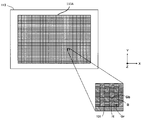
- FIG. 2 is a diagram for explaining a pixel array and a unit group of the imaging chip.
- FIG. 2 particularly shows a state where the imaging chip 113 is observed from the back side.
- An area where pixels are arranged in the imaging chip 113 is referred to as a pixel area 113A.
- a pixel area 113A 20 million or more pixels are arranged in a matrix.
- 16 pixels of 4 pixels ⁇ 4 pixels adjacent to each other form one unit group 131.
- the grid lines in FIG. 2 indicate a concept in which adjacent pixels are grouped to form a unit group 131.
- the number of pixels forming the unit group 131 is not limited to this, and may be about 1000, for example, 32 pixels ⁇ 64 pixels, or more or less.
- the unit group 131 includes four so-called Bayer arrays, which are composed of four pixels of green pixels Gb and Gr, a blue pixel B, and a red pixel R, vertically and horizontally.
- the green pixel is a pixel having a green filter as the color filter 102, and receives light in the green wavelength band of incident light.
- the blue pixel is a pixel having a blue filter as the color filter 102 and receives light in the blue wavelength band.
- the red pixel is a pixel having a red filter as the color filter 102 and receives light in the red wavelength band.
- FIG. 3 is a circuit diagram corresponding to the unit group of the imaging chip.
- a rectangle surrounded by a dotted line typically represents a circuit corresponding to one pixel. Note that at least some of the transistors described below correspond to the transistor 105 in FIG.
- the unit group 131 is formed of 16 pixels.
- the 16 PDs 104 corresponding to the respective pixels are each connected to the transfer transistor 302.
- the gate of each transfer transistor 302 is connected to a TX wiring 307 to which a transfer pulse is supplied.
- the TX wiring 307 is commonly connected to the 16 transfer transistors 302.
- each transfer transistor 302 is connected to the source of the corresponding reset transistor 303, and a so-called floating diffusion FD (charge detection unit) between the drain of the transfer transistor 302 and the source of each reset transistor 303 is connected to the amplifier transistor 304. Connected to the gate.
- the drain of each reset transistor 303 is connected to a Vdd wiring 310 to which a power supply voltage is supplied.
- the gate of each reset transistor 303 is connected to a reset wiring 306 to which a reset pulse is supplied.
- the reset wiring 306 is commonly connected to the 16 reset transistors 303.
- each amplification transistor 304 is connected to a Vdd wiring 310 to which a power supply voltage is supplied.
- the source of each amplification transistor 304 is connected to the drain of each corresponding selection transistor 305.
- the gate of each selection transistor 305 is connected to a decoder wiring 308 to which a selection pulse is supplied.
- the decoder wiring 308 is provided independently for each of the 16 selection transistors 305.
- the source of each selection transistor 305 is connected to a common output wiring 309.
- the load current source 311 supplies current to the output wiring 309. That is, the output wiring 309 for the selection transistor 305 is formed by a source follower. Note that the load current source 311 may be provided on the imaging chip 113 side or may be provided on the signal processing chip 111 side.
- a reset pulse is applied to the reset transistor 303 through the reset wiring 306.
- a transfer pulse is applied to the transfer transistor 302 through the TX wiring 307.
- the potentials of the PD 104 and the floating diffusion FD are reset.
- the PD 104 converts the incident light received into charges and accumulates them. Thereafter, when the transfer pulse is applied again without the reset pulse being applied, the charge accumulated in the PD 104 is transferred to the floating diffusion FD. As a result, the potential of the floating diffusion FD changes from the reset potential to the signal potential after charge accumulation.
- a selection pulse is applied to the selection transistor 305 through the decoder wiring 308, the change in the signal potential of the floating diffusion FD is transmitted to the output wiring 309 through the amplification transistor 304 and the selection transistor 305.
- the reset wiring 306 and the TX wiring 307 are common to the 16 pixels forming the unit group 131. That is, the reset pulse and the transfer pulse are simultaneously applied to all 16 pixels. Therefore, all the pixels forming the unit group 131 start charge accumulation at the same timing and end charge accumulation at the same timing. However, the pixel signal corresponding to the accumulated charge is selectively output to the output wiring 309 by sequentially applying the selection pulse to each selection transistor 305. In addition, the reset wiring 306, the TX wiring 307, and the output wiring 309 are provided separately for each unit group 131.
- the charge accumulation time can be controlled for each unit group 131.
- pixel signals with different charge accumulation times can be output between the unit groups 131. More specifically, while one unit group 131 performs charge accumulation once, the other unit group 131 repeats charge accumulation several times and outputs a pixel signal each time, so that Each frame for moving images can be output at a different frame rate between the unit groups 131.
- FIG. 4 is a block diagram showing a functional configuration of the image sensor.
- the analog multiplexer 411 sequentially selects the 16 PDs 104 that form the unit group 131. Then, the multiplexer 411 outputs each pixel signal of the 16 PDs 104 to the output wiring 309 provided corresponding to the unit group 131.
- the multiplexer 411 is formed on the imaging chip 113 together with the PD 104.
- the pixel signal of the analog signal output via the multiplexer 411 is amplified by the amplifier 412 formed in the signal processing chip 111. Then, the pixel signal amplified by the amplifier 412 is processed by a signal processing circuit 413 that performs correlated double sampling (CDS) and analog / digital (Analog / Digital) conversion, which is formed in the signal processing chip 111. Correlated double sampling signal processing is performed, and A / D conversion (conversion from an analog signal to a digital signal) is performed. The pixel signal is subjected to correlated double sampling signal processing in the signal processing circuit 413, whereby noise of the pixel signal is reduced. The A / D converted pixel signal is transferred to the demultiplexer 414 and stored in the pixel memory 415 corresponding to each pixel. The demultiplexer 414 and the pixel memory 415 are formed in the memory chip 112.
- CDS correlated double sampling
- analog / digital Analog / Digital
- the arithmetic circuit 416 processes the pixel signal stored in the pixel memory 415 and passes it to the subsequent image processing unit.
- the arithmetic circuit 416 may be provided in the signal processing chip 111 or may be provided in the memory chip 112. Note that FIG. 4 shows connections for one unit group 131, but actually these exist for each unit group 131 and operate in parallel. However, the arithmetic circuit 416 may not exist for each unit group 131. For example, one arithmetic circuit 416 may perform sequential processing while sequentially referring to the values in the pixel memory 415 corresponding to each unit group 131.
- the output wiring 309 is provided corresponding to each of the unit groups 131.
- the image sensor 100 is formed by stacking an image pickup chip 113, a signal processing chip 111, and a memory chip 112. For this reason, by using the electrical connection between the chips using the bumps 109 for the output wirings 309, the wirings can be routed without enlarging each chip in the surface direction.
- the pixel region 113A of the image sensor 100 is divided into a plurality of blocks.
- the plurality of blocks are defined to include at least one unit group 131 per block.
- pixels included in each block are controlled by different control parameters. That is, pixel signals having different control parameters are acquired for a pixel group included in a block and a pixel group included in another block.
- the control parameter include a charge accumulation time or accumulation count, a frame rate, a gain, a thinning rate, the number of addition rows or addition columns to which pixel signals are added, the number of digitization bits, and the like.
- the control parameter may be a parameter in image processing after obtaining an image signal from a pixel.
- the charge accumulation time refers to the time from the start of PD 104 accumulation until the end.
- the number of times of charge accumulation refers to the number of times the PD 104 accumulates charges per unit time.
- the frame rate is a value representing the number of frames processed (displayed or recorded) per unit time in a moving image.
- the unit of the frame rate is expressed by fps (Frames Per Second). The higher the frame rate, the smoother the movement of the subject in the video.
- the gain means a gain factor (amplification factor) of the amplifier 412.
- This ISO sensitivity is a photographic film standard established by ISO and represents how much light the photographic film can record.
- ISO sensitivity is also used when expressing the sensitivity of the image sensor 100.
- the ISO sensitivity is a value representing the ability of the image sensor 100 to capture light.
- Increasing the gain improves the ISO sensitivity. For example, when the gain is doubled, the electrical signal (pixel signal) is also doubled, and the brightness is appropriate even when the amount of incident light is half.
- the gain is increased, noise included in the electric signal is also amplified, so that noise increases.
- the thinning-out rate refers to the ratio of the number of pixels in which pixel signals are not read out with respect to the total number of pixels in a predetermined area. For example, when the thinning rate of a predetermined area is 0, it means that pixel signals are read from all pixels in the predetermined area. Further, when the thinning rate of the predetermined area is 0.5, it means that the pixel signal is read from half of the pixels in the predetermined area. Specifically, when the unit group 131 is a Bayer array, it is read as a pixel from which pixel signals are alternately read out every other unit of the Bayer array in the vertical direction, that is, every two pixels (two rows) of the pixel unit. Pixels that are not output are set.
- the resolution of the image is reduced when the pixel signal readout is thinned out.
- 20 million or more pixels are arranged in the image sensor 100, for example, even if thinning is performed at a thinning rate of 0.5, an image can be displayed with 10 million or more pixels. For this reason, it is considered that the reduction in resolution is not a concern for the user.
- the number of added rows refers to the number of vertical pixels (number of rows) to be added when pixel signals of pixels adjacent in the vertical direction are added.
- the number of added columns refers to the number of horizontal pixels (number of columns) to be added when pixel signals of pixels adjacent in the horizontal direction are added.
- Such addition processing is performed in the arithmetic circuit 416, for example.
- the arithmetic circuit 416 performs the process of adding the pixel signals of a predetermined number of pixels adjacent in the vertical direction or the horizontal direction, thereby obtaining the same effect as the process of reading out the pixel signals by thinning out at a predetermined thinning rate.
- the average value may be calculated by dividing the added value by the number of rows or columns added by the arithmetic circuit 416.
- the digitization bit number refers to the bit number when the signal processing circuit 413 converts an analog signal into a digital signal in A / D conversion. As the number of bits of the digital signal increases, brightness, color change, and the like are expressed in more detail.
- the accumulation condition refers to a condition related to charge accumulation in the image sensor 100.
- the accumulation condition refers to the charge accumulation time or number of accumulations, the frame rate, and the gain among the control parameters described above. Since the frame rate can change according to the charge accumulation time and the number of times of accumulation, the frame rate is included in the accumulation condition. Further, the amount of light for proper exposure changes according to the gain, and the charge accumulation time or number of times of accumulation can also change according to the amount of light for proper exposure. For this reason, the gain is included in the accumulation condition.
- the imaging condition is a condition related to imaging of the subject.
- the imaging condition refers to a control parameter including the above accumulation condition.
- the imaging conditions include control parameters (for example, charge accumulation time or accumulation count, frame rate, gain) for controlling the image sensor 100, as well as control parameters (for controlling reading of signals from the image sensor 100). For example, a thinning rate), a control parameter for processing a signal from the image sensor 100 (for example, the number of addition rows or addition columns for adding pixel signals, the number of digitization bits, the image processing unit 30 described later performs image processing) Is also included.
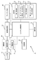
- FIG. 5 is a block diagram showing the configuration of the electronic device according to the first embodiment.
- the electronic device 1 includes a lens unit 10, an imaging unit 20, an image processing unit 30, a work memory 40, a display unit 50, an operation unit 55, a recording unit 60, and a system control unit 70.
- the lens unit 10 is an imaging optical system composed of a plurality of lens groups.
- the lens unit 10 guides the light flux from the subject to the imaging unit 20.
- the lens unit 10 may be integrated with the electronic device 1 or may be an interchangeable lens that can be attached to and detached from the electronic device 1. Further, the lens unit 10 may have a built-in focus lens or a zoom lens.
- the imaging unit 20 includes an imaging device 100 and a driving unit 21.
- the drive unit 21 is a control circuit that controls driving of the image sensor 100 in accordance with an instruction from the system control unit 70.
- the drive unit 21 controls the timing (or timing cycle) at which the reset pulse and the transfer pulse are applied to the reset transistor 303 and the transfer transistor 302, respectively, thereby reducing the charge accumulation time or accumulation count as a control parameter. Control.
- the drive unit 21 controls the frame rate by controlling the timing (or timing cycle) at which the reset pulse, the transfer pulse, and the selection pulse are applied to the reset transistor 303, the transfer transistor 302, and the selection transistor 305, respectively.
- the drive unit 21 controls the thinning rate by setting pixels to which the reset pulse, the transfer pulse, and the selection pulse are applied.
- the drive unit 21 controls the ISO sensitivity of the image sensor 100 by controlling the gain (also referred to as gain factor or amplification factor) of the amplifier 412.
- the driving unit 21 sends an instruction to the arithmetic circuit 416 to set the number of added rows or the number of added columns to which the pixel signals are added.
- the drive unit 21 sets the number of bits for digitization by sending an instruction to the signal processing circuit 413.
- the drive unit 21 performs block setting in the pixel area (imaging area) 113 ⁇ / b> A of the image sensor 100. In this way, the drive unit 21 functions as an image sensor control unit that causes the image sensor 100 to capture an image under different image capturing conditions for each of a plurality of blocks and output a pixel signal.
- the system control unit 70 instructs the drive unit 21 on the block position, shape, range, and the like.
- the image sensor 100 delivers the pixel signal from the image sensor 100 to the image processing unit 30.
- the image processing unit 30 uses the work memory 40 as a work space, performs various image processing on the raw image data composed of pixel signals of each pixel, and generates image data.
- the image processing unit 30 has a CPU, and the CPU executes various image processes. For example, the image processing unit 30 generates an RGB image signal by performing color signal processing on a signal obtained by the Bayer array.
- the image processing unit 30 performs image processing such as white balance adjustment, sharpness adjustment, gamma correction, and gradation adjustment on the RGB image signal. Further, the image processing unit 30 performs a process of compressing in a predetermined compression format (JPEG format, MPEG format, etc.) as necessary.
- the image data generated in the image processing unit 30 is recorded in the recording unit 60 via the system control unit 70. Further, the image data generated by the image processing unit 30 is output to the display unit 50 via the system control unit 70 and displayed on the display unit 50.
- the image processing unit 30 performs a process of synthesizing image data based on an image captured continuously a plurality of times, in addition to the above-described process. By such processing, noise is removed.
- Parameters that are referred to when the image processing unit 30 performs image processing are also included in the control parameters (imaging conditions). For example, parameters such as color signal processing, white balance adjustment, gradation adjustment, and compression rate are included in the control parameters.
- the signal read from the image sensor 100 changes according to the charge accumulation time, and the parameters referred to when performing image processing also change according to the change in the signal.
- the image processing unit 30 sets different control parameters for each block, and executes image processing such as color signal processing based on these control parameters.
- the image processing unit 30 extracts frames at predetermined timings from among a plurality of frames obtained in time series from the imaging unit 20. Alternatively, the image processing unit 30 discards frames at a predetermined timing among a plurality of frames obtained in time series from the imaging unit 20. Thereby, since the amount of data can be reduced, it is possible to reduce the load of subsequent processing. Further, the image processing unit 30 calculates one or a plurality of frames to be interpolated between the frames based on a plurality of frames obtained in time series from the imaging unit 20. Then, the image processing unit 30 adds the calculated one or more frames between the frames. As a result, a moving image with smoother motion can be reproduced during moving image reproduction.
- the drive part 21 is comprised so that the thinning-out rate may be controlled, it is not restricted to such a structure.
- the drive unit 21 reads pixel signals from all pixels, but the image processing unit 30 or the arithmetic circuit 416 controls the thinning rate by discarding predetermined pixel signals out of the read pixel signals. Good.
- the work memory 40 temporarily stores image data and the like when image processing by the image processing unit 30 is performed.
- the display unit 50 is configured by a liquid crystal display panel, for example. As shown in FIG. 5, the display unit 50 includes a first display unit 51, a first touch panel (selection unit, first operation unit) 52, a second display unit 53, and a second touch panel (first touch panel). 2 operation part) 54.
- the first display unit 51 displays images (still images, moving images, live view images) captured by the imaging unit 20 and various types of information.
- the first touch panel 52 is formed on the display screen of the first display unit 51.
- the first touch panel 52 outputs a signal indicating a position touched by the user to the system control unit 70 when the user designates an area.
- the second display unit 53 displays a menu for the user to set imaging conditions (control parameters).
- the second touch panel 54 is formed on the display screen of the second display unit 53.
- the second touch panel 54 outputs a signal indicating the position touched by the user to the system control unit 70 when the user sets the imaging condition.
- the operation unit 55 includes a shutter button, a recording start button, and various operation switches that are operated by the user.
- the operation unit 55 outputs a signal corresponding to the operation by the user to the system control unit 70.
- the recording unit 60 has a card slot into which a storage medium such as a memory card can be mounted.
- the recording unit 60 stores the image data and various data generated by the image processing unit 30 in a recording medium mounted in the card slot.
- the recording unit 60 has an internal memory.
- the recording unit 60 may be configured to record the image data and various data generated by the image processing unit 30 in an internal memory.
- the system control unit 70 controls the overall processing and operation of the electronic device 1.
- the system control unit 70 has a CPU (Central Processing) Unit).
- the system control unit 70 divides the imaging surface (pixel area 113A) of the imaging device 100 (imaging chip 113) into a plurality of blocks, and different charge accumulation times (or charge accumulation times) and frame rates among the blocks. Get an image with a gain. Therefore, the system control unit 70 instructs the drive unit 21 about the block position, shape, range, and accumulation condition for each block.
- the system control unit 70 causes an image to be acquired with a different thinning rate between blocks, the number of addition rows or addition columns to which pixel signals are added, and the number of digitization bits.
- the system control unit 70 instructs the drive unit 21 on the imaging conditions for each block (the thinning rate, the number of added rows or columns to which pixel signals are added, and the number of digitization bits). Further, the image processing unit 30 executes image processing under imaging conditions (control parameters such as color signal processing, white balance adjustment, gradation adjustment, and compression rate) that are different between blocks. For this reason, the system control unit 70 instructs the image processing unit 30 on the imaging conditions for each block (control parameters such as color signal processing, white balance adjustment, gradation adjustment, and compression rate).
- the system control unit 70 causes the recording unit 60 to record the image data generated in the image processing unit 30. Further, the system control unit 70 causes the first display unit 51 of the display unit 50 to display an image by outputting the image data generated in the image processing unit 30 to the display unit 50. Alternatively, the system control unit 70 reads out the image data recorded in the recording unit 60 and outputs the image data to the display unit 50, thereby causing the first display unit 51 of the display unit 50 to display an image.
- the images displayed on the first display unit 51 include still images, moving images, and live view images.
- the live view image is an image displayed on the first display unit 51 by sequentially outputting the image data generated by the image processing unit 30 to the display unit 50.
- the live view image is used for the user to confirm the image of the subject imaged by the imaging unit 20.
- the live view image is also called a through image or a preview image.
- the image processing unit 30 is realized by the CPU executing processing based on the control program.
- the system control unit 70 is realized by the CPU executing processing based on the control program.
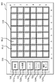
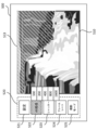
- FIG. 6 is a diagram showing an example of a display screen in the display unit.
- the display screen 500 of the display unit 50 is provided with an image display area 510 and an operation button display area 520.
- the image display area 510 is an area for displaying an image captured by the imaging unit 20, that is, a still image, a moving image, and a live view image.
- the operation button display area 520 is an area for displaying a menu for the user to set imaging conditions and the like.
- the image display area 510 and the operation button display area 520 are provided in one display screen 500.
- the image display area 510 corresponds to the first display unit 51
- the operation button display area 520 corresponds to the second display unit 53.
- a plurality of blocks B (i, j) are set.
- a first touch panel 52 is provided on the image display area 510.
- a plurality of touch areas P (i, j) are formed so as to overlap each of the plurality of blocks B (i, j).
- the operation button display area 520 is provided in the vicinity of the image display area 510.
- a menu for the user to set the area, imaging conditions, and imaging mode is displayed.
- a menu for setting a region by the user is a setting button 521.
- the menu for the user to set imaging conditions includes an ISO sensitivity button 522 (also referred to as a menu related to gain), a shutter speed button 523 (also referred to as a menu related to charge accumulation time), and a frame.
- a rate button 524 (which is also referred to as a frame rate menu).
- the menu for the user to set the shooting mode is a shooting mode button 525.
- setting button 521 the ISO sensitivity button 522, the shutter speed button 523, the frame rate button 524, and the shooting mode button 525 are simply referred to as “setting 521”, “ISO sensitivity 522”, respectively.
- the setting 521 is a button that is pressed when the user sets (selects) an area in the image display area 510 in units of blocks.
- the ISO sensitivity 522 is a button that is pressed when the user sets the ISO sensitivity (that is, gain).
- the shutter 523 is a button that is pressed when the user sets the shutter speed (that is, the exposure time). The shutter speed corresponds to the charge accumulation time.
- the frame rate 524 is a button that is pressed when the user sets the frame rate of a moving image or a live view image.
- the shooting mode 525 is a button that is pressed when the user selects whether to manually set the imaging condition or to automatically set the imaging condition.
- the second touch panel 54 is provided on the operation button display area 520.
- the touch area 521 a is formed so as to overlap the setting 521.
- the touch area 522 a is formed so as to overlap the ISO sensitivity 522.
- the touch area 523 a is formed so as to overlap the shutter 523.
- the touch area 524a is formed to overlap the frame rate 524.
- the touch area 525a is formed so as to overlap the shooting mode 525.
- the first touch panel 52 and the second touch panel 54 may be configured with separate touch panels or may be configured with one touch panel.
- the touch area P (i, j) of the touch panel corresponds to the first touch panel 52
- the touch areas 521a to 525a correspond to the second touch panel 54.
- FIG. 7 is a functional block diagram of the image processing unit and the system control unit in the first embodiment.
- the image processing unit 30 includes a synthesis processing unit 31.
- the synthesis processing unit 31 performs a process of synthesizing images picked up multiple times at high speed. By such processing, noise included in the image is reduced. That is, this process functions as a noise reduction.
- the system control unit 70 includes a display control unit (control unit) 71, a change unit 72, a selection unit 73, and an imaging control unit (image composition unit) 74.
- the display control unit 71 performs control to display an image (still image, moving image, live view image) on the first display unit 51 by outputting the image data to the display unit 50.
- the display control unit 71 performs control for displaying a preset menu image on the second display unit 53.
- the changing unit 72 performs control to change the imaging condition (including the accumulation condition) according to the touch operation of the second touch panel 54 by the user or automatically.
- the selection unit 73 performs control to select an area in the image display area 510 in units of blocks in response to a touch operation on the first touch panel 52 by the user.
- the imaging control unit (image composition unit) 74 executes imaging control according to the operation of the shutter button (operation unit 55) by the user.
- the “first area” is a selection unit in the image display area 510 of the display screen 500 according to a user operation or automatically.
- the “second area” refers to an area in the pixel area 113 ⁇ / b> A of the image sensor 100 corresponding to an area selected by the selection unit 73 in response to a user operation in the image display area 510 of the display screen 500. Refers to an area.
- the first region and the second region may be one and the other of the two divided regions, or may be one of the regions divided into three or more and the other.
- FIG. 8 is a flowchart for explaining a photographing operation executed by the system control unit according to the first embodiment.
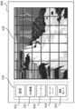
- 9 to 12 are diagrams showing display examples of the display screen when a small number of blocks are set in the image display area.
- the system control unit 70 starts the shooting operation (step S1). ).
- the user performs an operation of selecting whether to shoot a still image or a moving image in advance.
- the display control unit 71 displays the live view image captured by the imaging unit 20 on the first display unit 51 (image display area 510) (step S2).
- a waterfall live view image is displayed in the image display area 510.
- the user selects an area in the image display area 510, the user touches the setting 521 (that is, the touch area 521a) with a finger.
- an area in the image display area 510 can be selected, that is, the first touch panel 52 can detect a touch operation.
- the user touches the block B (i, j) set in the image display area 510 with a finger (or traces with the finger) to select an area in the image display area 510 in units of blocks.
- the first touch panel 52 outputs a detection signal corresponding to the touch area P (i, j) touched by the user to the system control unit 70.
- the selection unit 73 recognizes the area selected by the user based on the detection signal from the first touch panel 52.
- the area 511 is selected by the user.
- This region 511 is a background region behind the waterfall (a region with a white line in FIG. 10).
- the area 511 includes blocks B (3, 1) to B (8, 1), B (4, 2) to B (8, 2), B (5, 3) to B (8, 3). ), B (6, 4) to B (8, 4).
- the selection unit 73 determines whether or not an area has been selected by the user (step S3). If it is determined that the area is selected by the user, the selection unit 73 sets the area 511 selected by the user (step S4). Specifically, the selection unit 73 outputs an instruction signal that instructs the drive unit 21 of the position of the block selected by the user.
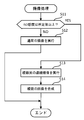
- the changing unit 72 determines whether or not the auto mode (automatic mode) has been selected as the shooting mode by the user (step S5).
- the user touches the shooting mode 525 (that is, the touch area 525a). Then, the user selects a manual mode (manual mode) or an auto mode (automatic mode) among the photographing modes.
- the changing unit 72 determines that the auto mode is not selected as the shooting mode, that is, when it is determined that the manual mode is selected as the shooting mode, the imaging condition is determined according to the operation of the second touch panel 54 by the user. (Including storage conditions) is set (step S6).
- the user touches the ISO sensitivity 522 (that is, the touch area 522a).
- the second touch panel 54 outputs a detection signal corresponding to the touch area 522 a touched by the user to the system control unit 70.
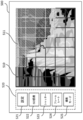
- the display control unit 71 displays a plurality of ISO sensitivity values next to the ISO sensitivity 522. In the example illustrated in FIG. 11, “100”, “200”, “400”, “800”, and “1600” are displayed as the ISO sensitivity.
- the changing unit 71 sets a new touch area on the second touch panel 54 so as to overlap the area of each value of ISO sensitivity.
- the user touches one of the ISO sensitivity values.
- the second touch panel 54 outputs a detection signal corresponding to the touch area touched by the user to the system control unit 70.
- the changing unit 72 sets the ISO sensitivity value touched by the user. Specifically, the changing unit 72 outputs an instruction signal for instructing a gain corresponding to the ISO sensitivity selected by the user to the driving unit 21.
- the user performs the same operation as the ISO sensitivity setting when setting the shutter speed (charge accumulation time) and frame rate. That is, the user touches the shutter 523 (that is, the touch area 523a) or the frame rate 524 (that is, the touch area 524a) when setting the shutter speed or the frame rate as the imaging condition.
- the second touch panel 54 outputs a detection signal corresponding to the touch area 523a or 524a touched by the user to the system control unit 70.
- the display control unit 71 displays a plurality of shutter speed or frame rate values next to the shutter 523 or the frame rate 524.
- the user touches either the shutter speed or the frame rate value.
- the change unit 72 sets the shutter speed or frame rate value touched by the user. Specifically, the changing unit 72 outputs an instruction signal for instructing the shutter speed or frame rate selected by the user to the driving unit 21.
- the driving unit 21 receives an instruction signal that instructs the area of the pixel area 113A corresponding to the area 511 selected by the user in units of blocks. Further, the drive unit 21 receives an instruction signal for instructing an imaging condition selected by the user. In response to this, the drive unit 21 drives the imaging unit 20 so as to perform imaging in the designated imaging condition (shutter speed, ISO sensitivity, frame rate) in the region of the pixel region 113A corresponding to the region 511.
- the shutter speed is set when capturing a still image
- the frame rate is set when capturing a moving image.
- the image (live view image in the region 511) displayed in the region 511 in the image display region 510 changes.
- the ISO sensitivity is increased, the subject is brightly imaged even with a small amount of light. Also, the dark part of the live view image becomes brighter.
- the shutter speed is increased, blurring of a moving subject is reduced. Further, when the frame rate is increased, the movement of the subject in the moving image becomes smooth.
- the user can confirm the image of the selected region that changes in accordance with the change in the imaging condition in the live view image by selecting the region and setting the imaging condition in the selected region.
- the imaging condition selected by the user may not be a condition suitable for proper exposure.
- the user can also recognize that the exposure condition is overexposed or underexposed by changing the imaging condition.
- the user can recognize how the image changes when the imaging condition is changed. Therefore, the user can take an image after creating an image by changing the imaging conditions before taking the image.
- steps S1 to S6 as described above are repeated until the user performs a half-pressing operation (step S8) of the shutter (recording start button when shooting a moving image) of the operation unit 55.
- a half-pressing operation step S8 of the shutter (recording start button when shooting a moving image) of the operation unit 55.
- an area 512 other than the area 511 is selected from the image display area 510.
- the live view image displayed in the area 512 in the image display area 510 changes according to the selection of the ISO sensitivity 522, the shutter 523, and the frame rate 524 by the user.
- a region 512 shown in FIG. 12 is a waterfall region (a region with a white line in FIG. 12).
- the area 512 includes blocks B (1,1) to B (2,1), B (1,2) to B (3,2), B (1,3) to B (4,3 ), B (1,4) to B (5,4), B (1,5) to B (8,5), B (1,6) to B (8,6).
- the changing unit 72 automatically sets the imaging condition of the area 511 selected by the user (step S7). At this time, the changing unit 72 changes the imaging condition based on at least one of the contrast and the color change of the image in the region 511 in the live view image. For example, the changing unit 72 changes the imaging conditions (ISO sensitivity, shutter speed, frame rate) so that the contrast between the bright part and the dark part of the image in the region 511 is maximized. The changing unit 72 changes the imaging conditions (ISO sensitivity, shutter speed, frame rate) so that the color change of the image in the region 511 becomes the most vivid. In addition, the changing unit 72 changes the imaging condition so that the contrast of the image in the region 511 is maximized and the color change of the image in the region 511 is the most vivid.
- the imaging conditions ISO sensitivity, shutter speed, frame rate
- step S8 The processing when the auto mode is selected as the photographing mode (steps S1 to S5, S7) is repeatedly executed until the user performs a half-pressing operation (step S8) of the shutter of the operation unit 55.
- the changing unit 72 automatically sets the imaging condition based on at least one of the contrast and the color change of the image in the region 512 (step S7).
- the live view images displayed in the areas 511 and 512 in the image display area 510 change according to the ISO sensitivity, shutter speed, or frame rate value changed by the changing unit 72.
- the imaging conditions for each area that can be set by the user are not limited to ISO sensitivity, shutter speed, and frame rate.
- the above-described thinning rate, the number of addition rows or addition columns to which pixel signals are added, the number of digitization bits, and the like may be set as imaging conditions for each region.
- parameters such as color signal processing, white balance adjustment, gradation adjustment, and compression rate may be set as imaging conditions for each region.
- the system control unit 70 determines whether or not a half-pressing operation (SW1 operation) of the shutter or the recording start button has been performed (step S8).
- the half-press operation is used as an instruction to start shooting preparation.
- the system control unit 70 performs auto focus (AF) control and the like for automatically performing focus adjustment.
- the system control unit 70 determines whether or not the shutter or the recording start button is fully pressed (SW2 operation) (step S9). If it is determined that the full-press operation has been performed, the imaging control unit 74 performs an imaging process that causes the imaging element 100 to perform imaging (step S10).
- FIG. 13 is a flowchart illustrating an example of an imaging process according to the first embodiment.
- the imaging control unit 74 determines whether or not the ISO sensitivity is set to a predetermined value or higher by the user or automatically (step S11). If the imaging control unit 74 determines that the ISO sensitivity is not set to a predetermined value or higher, the imaging control unit 74 causes the imaging unit 20 to perform normal imaging (step S12). That is, a still image is acquired by one imaging as usual. At this time, imaging is performed according to the imaging conditions for each region selected as described above.
- the imaging control unit 74 instructs the image processing unit 30 to synthesize a plurality of images that have been continuously captured a plurality of times (step S14).
- the composition processing unit 31 composes a plurality of images based on an instruction from the imaging control unit 74 and generates a still image.
- the ISO sensitivity is increased, noise is likely to occur.
- noise is reduced by combining a plurality of images captured at high speed.
- step S10 when imaging a moving image, the imaging control part 74 performs normal imaging, without performing the process shown to step S11 of FIG. 13 (step S12). That is, in the case of capturing a moving image, a plurality of continuous images and a combination of a plurality of images shown in step S13 are not performed.
- each block set in the image display area 510 is a large area block. However, blocks in an area smaller than the blocks shown in FIGS. 9 to 12 may be set in the image display area 510.
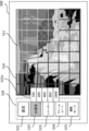
- 14 to 16 are diagrams showing display examples of the display screen when a large number of blocks are set in the image display area. In the examples shown in FIGS. 14 to 16, the block is the same area as the unit group or an area including several unit groups.
- the user When the user selects an area, after touching the setting 521, the user traces his / her finger along the boundary of the area to be selected as shown in FIG. By such a selection method, a region can be selected more finely.
- the operation for changing the imaging condition is the same as that described with reference to FIGS. That is, as shown in FIG. 14, the user selects a region 513.
- This region 513 is the background region behind the waterfall (the region where the white line in FIG. 14 is drawn).
- the user touches the ISO sensitivity 522 a plurality of ISO sensitivity values appear next to the ISO sensitivity 522 as shown in FIG.
- the user touches one of the ISO sensitivity values to set the ISO sensitivity.
- the user touches the shutter 523 or the frame rate 524 to set the shutter speed or the frame rate.
- the user touches the setting 521, the user selects the area 514 by tracing his / her finger along the boundary of the area to be selected as shown in FIG. Then, as described above, the user touches the ISO sensitivity 522, the shutter 523, and the frame rate 524 to set the ISO sensitivity, shutter speed, and frame rate in the area 514. Similarly to the case described with reference to FIG. 9 to FIG. 12, it is possible to automatically change the imaging condition for each area by touching the imaging mode 525 and changing the imaging mode. .
- the imaging unit 20 that includes the imaging device 100 and can capture the first region and the second region, and the first region and the second region captured by the imaging unit 20 are used.
- a control unit 71 that displays a live view image corresponding to the area on the display unit 50, and a changing unit 72 that makes the accumulation condition of the first area of the live view image different from the accumulation condition of the second area are included.
- a change in the image corresponding to the change in the accumulation condition for each region can be confirmed in the live view image. Therefore, the user can create an image by changing the imaging conditions for each region before starting to capture a still image or a moving image. It can be said that such processing performs editing before imaging of an image.
- the changing unit 72 is configured to make the accumulation time of the first area different from the accumulation time of the second area. Accordingly, the user can edit an image with different accumulation times (shutter speeds) for each region, and can take an image after confirming the edited image.
- the changing unit 72 is configured to make the frame rate of the first area different from the frame rate of the second area. Therefore, the user can edit the image by changing the frame rate for each region, and can take an image after confirming the edited image.
- the changing unit 72 is configured to make the gain of the first region different from the gain of the second region. Therefore, the user can edit the image with different gains (ISO sensitivity) for each region, and can take an image after confirming the edited image.
- the changing unit 72 is configured to make the accumulation condition of the first area different from the accumulation condition of the second area based on at least one of the contrast and the color change of the live view image. Therefore, an optimum accumulation condition can be automatically set for each region based on at least one of contrast and color change.
- a selection unit 73 capable of selecting the first area and the second area of the live view image is provided. Therefore, the user can select an arbitrary area. Or the selection part 73 can select the area
- the selection unit 73 includes the first operation unit 52 that selects a part of the live view image, the user can select an area while viewing the live view image. Moreover, since the 1st operation part 52 has the touchscreen formed in the display part 50, the user can select an area
- the second operation unit 54 for selecting a menu (setting 521 in the operation button display area 520, ISO sensitivity 522, shutter 523, frame rate 524, shooting mode 525) is provided, the user can perform imaging conditions by touching the touch panel. Etc. can be selected. For this reason, an imaging condition etc. can be selected easily by simple operation.
- the control unit 71 displays at least one of a menu related to gain (ISO sensitivity 522), a menu related to accumulation time (shutter 523), and a menu related to frame rate (frame rate 524), the gain and accumulation time are displayed. And at least one of the frame rates can be selected by a touch operation on the touch panel. Further, since the control unit 71 displays the menu in the vicinity of the live view image, it is possible to change the imaging condition while confirming the change of the live view image corresponding to the change of the imaging condition. Therefore, the operability by the user is improved.
- the electronic device 1 according to the first embodiment shown in FIG. 5 includes devices such as a digital camera, a smartphone, a mobile phone, and a personal computer having an imaging function.
- the display unit 50 may be provided outside the electronic device.
- each of the system control unit 70 and the display unit 50 is provided with a communication unit that transmits and receives signals (image data, control signals, and the like) by wire or wirelessly.
- the image processing unit 30 and the system control unit 70 may be configured integrally. In this case, the system control unit having one CPU executes the processing based on the control program, thereby taking on the functions of the image processing unit 30 and the system control unit 70.
- the selection of the area in the image display area 510 is performed manually.
- the selection of the area can also be performed automatically (automatically).
- the region and the imaging condition are set according to the movement of the moving subject.
- the second embodiment also has a function of imaging only an area selected by the user or an area automatically selected.
- FIG. 17 is a functional block diagram of the image processing unit and the system control unit in the second embodiment.
- the image processing unit 30 ⁇ / b> A includes a synthesis processing unit 31 and a detection unit 32. Since the composition processing unit 31 has the same configuration as that described with reference to FIG.
- the detection unit 32 performs a process of detecting a moving subject (for example, a waterfall shown in FIG. 9 or the like).
- the configuration of the system control unit 70 is the same as the configuration described with reference to FIG.
- the configuration (lens unit 10, imaging unit 20, work memory 40, display unit 50, recording unit 60) other than the image processing unit 30 and the system control unit 70 is the same as the configuration shown in FIG.
- FIG. 18 is a flowchart for explaining a photographing operation executed by the system control unit according to the second embodiment.
- the system control unit 70 starts shooting (step S1). ).
- the display control unit 71 displays the live view image captured by the imaging unit 20 on the first display unit 51 (image display area 510) (step S2).
- the user sets the shooting mode.
- the shooting mode 525 that is, the touch area 525a
- a manual mode manual mode
- an auto mode automatic mode
- the system control unit 70 determines whether or not auto is selected as the shooting mode 525 (step S21). When it is determined that the auto mode is not selected as the shooting mode, that is, when it is determined that the manual mode is selected as the shooting mode, the selection unit 73 performs the same processing as steps S3 and S4 illustrated in FIG. . Subsequently, the changing unit 72 performs the same process as step S6 shown in FIG.
- the selection unit 73 automatically sets the area and the imaging condition based on the live view image displayed in the image display area 510 (step S22). .
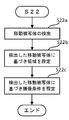
- FIG. 19 is a flowchart showing an example of the automatic setting process (step S22) of the area and the imaging condition.
- the system control unit 70 instructs the image processing unit 30 to detect a moving subject (step S22a).
- the detection unit 32 compares a plurality of image data obtained in a time series from the live view image, and detects a moving subject and a non-moving subject (subject that has not moved). Then, the detection unit 32 outputs the detection result to the system control unit 70 together with the image data.
- the selection unit 73 sets a moving subject region and a non-moving subject region based on the detection result of the detection unit 32 (step S22b).
- the changing unit 72 sets imaging conditions for the moving subject region and the non-moving subject region based on the detection result of the detecting unit 32 (step S22c). For example, for the moving subject area, the ISO sensitivity is increased and the shutter speed is increased. When a moving image is being captured, the frame rate of the moving subject area is set higher than the frame rate of the non-moving subject area. For the non-moving subject area, the ISO sensitivity is made lower than the ISO sensitivity of the moving subject area, and the shutter speed is made slower than the shutter speed of the moving subject area. When a moving image is being captured, the frame rate of the non-moving subject area is set lower than the frame rate of the moving subject area.
- the area and imaging condition automatic setting processing shown in FIG. 19 is an example, and the area and imaging conditions may be set by other methods.
- the selection unit 73 sets the region by specifying the boundary of the region based on the contrast and color change between the bright part and the dark part in the live view image. May be.
- the changing unit 72 may change the imaging condition based on at least one of the contrast and the color change of the image in the region 511 in the live view image. You may apply combining the process which sets such an area
- the system control unit 70 determines whether or not a half-press operation (SW1 operation) of the shutter or the recording start button has been performed (step S8). When the half-press operation is performed, the system control unit 70 determines whether or not the shutter or the recording start button is fully pressed (the operation of SW2) (step S9). If it is determined that the full-press operation has been performed, the imaging control unit 74 performs an imaging process that causes the imaging element 100 to perform imaging (step S23).
- SW1 operation half-press operation
- FIG. 20 is a flowchart illustrating an example of an imaging process according to the second embodiment.
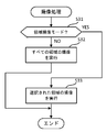
- the imaging control unit 74 determines whether or not the area imaging mode is set by the user (step S31).
- the area imaging mode is a mode in which imaging is performed only for an area selected by the user or an automatically set area.
- the user sets the area imaging mode by operating the operation unit 55, the second touch panel 54 (for example, a touch operation in the shooting mode 525), or the like before executing the imaging process.
- the imaging control unit 74 determines that the area imaging mode is not set, the imaging control unit 74 executes imaging for all the areas of the image display area 510 (step S32). In this case, for example, processing similar to steps S11 to S14 in FIG. 13 is performed. On the other hand, when it is determined that the area imaging mode is set, the imaging control unit 74 executes imaging only for the area selected in the image display area 510 (step S33). At this time, imaging is performed under imaging conditions set in the selected area.
- FIG. 21 is a diagram showing a display example of the display screen when only the selected area is imaged. As shown in FIG. 21, when the waterfall region 513 is selected, only the region 513 is imaged, and the other regions are not imaged.
- the detection unit 32 that detects the moving subject is provided, and the changing unit 72 determines the accumulation condition of the first region and the second region according to the detection result of the detection unit 32.
- the storage conditions are different from each other. Accordingly, it is possible to set an imaging condition suitable for the movement of the moving subject.
- the selection unit 73 is configured to set the first region and the second region according to the detection result of the detection unit 32. Therefore, the area of the moving subject can be reliably extracted. Also in the second embodiment, the same effects as those described in the first embodiment can be obtained.
- the second embodiment has a function of imaging only the area selected by the user or the area automatically selected. Therefore, it is possible to perform imaging only for an area that the user wants to image. According to such a configuration, the user can acquire various material images having high utility value, for example.
- the imaging conditions for each region that can be set by the user are not limited to ISO sensitivity, shutter speed, and frame rate.
- the above-described thinning rate, the number of addition rows or addition columns to which pixel signals are added, the number of digitization bits, and the like may be set as imaging conditions for each region.
- parameters such as color signal processing, white balance adjustment, gradation adjustment, and compression rate may be set as imaging conditions for each region.
- the image processing unit 30A is realized by the CPU executing a process based on the control program.
- FIG. 22 is a block diagram illustrating configurations of an imaging apparatus and an electronic apparatus according to the third embodiment.
- the imaging apparatus 1A is an apparatus that captures an image of a subject.
- the imaging apparatus 1A includes a lens unit 10, an imaging unit 20, an image processing unit 30, a work memory 40, an operation unit 55, a recording unit 60, and a first system control unit 70A.
- the configurations of 10, the imaging unit 20, the image processing unit 30, the work memory 40, the operation unit 55, and the recording unit 60 are the same as those illustrated in FIG. Accordingly, the same components are denoted by the same reference numerals, and redundant description is omitted.
- the electronic device 1B is a device that displays images (still images, moving images, live view images).
- the electronic apparatus 1B includes a display unit 50 and a second system control unit (control unit) 70B.
- the configuration of the display unit 50 in the electronic device 1B is the same as the configuration illustrated in FIG. Accordingly, the same components are denoted by the same reference numerals, and redundant description is omitted.
- the first system control unit 70A includes a first communication unit 75A.
- the second system control unit 70B has a second communication unit 75B.
- the first communication unit 75A and the second communication unit 75B transmit and receive signals to each other in a wired or wireless manner.
- the first system control unit 70A has only a configuration corresponding to, for example, the imaging control unit 74 in the configuration illustrated in FIG.
- the second system control unit 70B has a configuration corresponding to, for example, the display control unit 71, the change unit 72, and the selection unit 73 in the configuration illustrated in FIG.
- the first system control unit 70A receives the second image data (the image data image-processed by the image processing unit 30 and the image data recorded in the recording unit 60) via the first communication unit 75A. It transmits to the communication part 75B.
- the second system control unit 70B causes the display unit 50 to display the image data received by the second communication unit 75B. Further, the second system control unit 70B causes the second display unit 53 to display a preset menu image.
- the second system control unit 70B performs control to change the imaging condition (including the accumulation condition) according to the touch operation of the second touch panel 54 by the user or automatically. Further, the second system control unit 70B performs control for selecting an area in the image display area 510 in block units in response to a touch operation of the first touch panel 52 by the user or automatically.
- the first system control unit 70A executes imaging control in accordance with an operation of a shutter button (an operation unit that instructs to start capturing a still image or a moving image provided on the electronic device 1B side) by the user.
- 7 (display control unit 71, change unit 72, selection unit 73, and imaging control unit 74) may be provided in either the first system control unit 70A or the second system control unit 70B. 7 may be provided in the first system control unit 70A or the second system control unit 70B, and a part of the configuration shown in FIG. 7 is provided in the first system control unit 70A. 7 may be provided in the second system control unit 70B.
- the imaging device 1A includes, for example, a digital camera, a smartphone, a mobile phone, and a personal computer that have an imaging function and a communication function
- the electronic device 1B includes, for example, a smartphone, a mobile phone, and a portable personal computer that have a communication function. Consists of a portable terminal such as a computer.
- the image processing unit 30 shown in FIG. 22 is realized by the CPU executing processing based on the control program. Further, the first system control unit 70A illustrated in FIG. 22 is realized by the CPU executing processing based on the control program. Further, the second system control unit 70B shown in FIG. 22 is realized by the CPU executing processing based on the control program.
- the display unit 50 that includes the imaging device 100 and can display the live view image captured by the imaging unit 20 that captures the first region and the second region, and the imaging Control that causes the display unit 50 to display a menu for setting imaging conditions for the live view image when live view images corresponding to the first area and the second area captured by the unit 20 are displayed on the display unit 50.
- the live view image captured by the imaging device 1A is edited using a mobile terminal such as a smartphone, and the edited live view image is confirmed. Imaging can be performed above.
- the image processing unit 30 and the first system control unit 70A may be configured integrally.
- the system control unit having one CPU performs the processing based on the control program, thereby performing the function of the image processing unit 30 and the function of the first system control unit 70A.
- buttons 521 to 525 are arranged in a predetermined order. That is, the setting 521 is arranged at the top, the ISO sensitivity 522 is arranged second from the top (ie, below the setting 521), and the shutter 523 is arranged third from the top (ie, below the ISO sensitivity 522), The frame rate 524 is arranged fourth from the top (ie, below the shutter 523), and the shooting mode 525 is arranged at the bottom.
- the display control unit 71 changes the arrangement of the buttons 521 to 525 in accordance with the subject in the area to display.
- the display control part 71 displays a button with a high priority by the display mode different from the display mode of another button.
- FIG. 23 is a diagram showing a display example of the display screen in the fourth embodiment.
- the setting 521 is arranged at the top
- the shutter 523 is arranged second from the top (ie, below the setting 521)
- the frame rate 524 is third from the top (ie, below the shutter 523).
- the ISO sensitivity 522 is arranged fourth from the top (that is, below the frame rate 524), and the shooting mode 525 is arranged at the bottom.
- the shutter 523 is a button in a larger area than the other buttons (setting 521, ISO sensitivity 522, frame rate 524, shooting mode 525).
- the touch area 521a is formed so as to overlap the setting 521. Further, the touch area 523 a is formed so as to overlap the shutter 523. Further, the touch area 524a is formed to overlap the frame rate 524. Further, the touch area 522 a is formed so as to overlap the ISO sensitivity 522. Further, the touch area 525a is formed so as to overlap the shooting mode 525. Note that the touch area 523a is larger than the other button areas in accordance with the size of the shutter 523 area.
- the system control unit 70 instructs the image processing unit 30 to detect a moving subject.
- the detection unit 32 detects a moving subject and a non-moving subject by comparing a plurality of image data obtained in time series from the live view image. Then, the detection unit 32 outputs the detection result to the system control unit 70 together with the image data.
- the display control unit 71 determines whether a moving subject is included in the area selected by the selection unit 73 based on the detection result of the detection unit 32. If the display control unit 71 determines that the moving subject is included in the area selected by the selection unit 73, the display control unit 71 raises the shutter 523, which is a button for setting the shutter speed, as shown in FIG. Is displayed at the second position. In addition, the display control unit 71 displays the shutter 523 larger than the other buttons.
- the way the moving subject is captured changes due to the change in shutter speed. For example, when the moving subject is a waterfall, by increasing (fastening) the shutter speed, the image of the waterfall waterfall stops instantaneously. On the other hand, by lowering (slowing) the shutter speed, an image in which the waterfall water flow looks like a thread is obtained. Thus, for a moving subject, the shutter speed has a greater effect on how the subject is photographed than in other imaging conditions. Therefore, the display control unit 71 determines that the priority of the shutter speed is higher than other imaging conditions when a moving subject is included in the area. Then, the display control unit 71 moves the position of the shutter 523 upward and displays the shutter 523 as a button in a large area.
- a button with a high priority is arrange
- a button with a higher priority that is, an imaging condition
- the user can be prompted to operate a button with a higher priority.
- the frame rate greatly affects the smoothness of movement of the moving subject. Therefore, when capturing a moving subject moving image, the display control unit 71 determines that the priority of the frame rate is higher than other imaging conditions. Then, the display control unit 71 moves the position of the frame rate 524 upward and displays the frame rate 524 as a button in a large area.
- the display control unit 71 changes the button arrangement and the display mode (size) depending on whether or not the subject in the area is a moving subject.
- the configuration is not limited to this. .
- the system control unit 70 instructs the image processing unit 30 to detect the brightness of the image.
- the image processing unit 30 detects the brightness of the image in the region based on the live view image. Then, the image processing unit 30 outputs the detection result to the system control unit 70 together with the image data.
- the display control unit 71 determines whether the brightness of the image in the area selected by the selection unit 73 is a value within a predetermined range based on the brightness detection result by the image processing unit 30. When the display control unit 71 determines that the brightness of the image in the region is not a value within the predetermined range, the display control unit 71 displays the ISO sensitivity 522 that is a button for setting the ISO sensitivity at the second position from the top. In addition, the display control unit 71 displays the ISO sensitivity 522 larger than other buttons.
- the display control unit 71 determines that the priority of ISO sensitivity is higher than other imaging conditions when the image in the region is not a value within the predetermined range. Then, the display control unit 71 moves the position of the ISO sensitivity 522 upward and displays the ISO sensitivity 522 as a button in a large area.
- a button with a high priority is arrange
- a button with a higher priority that is, an imaging condition
- the user can be prompted to operate a button with a higher priority.
- a display mode that makes a high-priority button stand out a display mode that changes the color of the button or blinks the button in addition to increasing the button may be used.
- a plurality of imaging condition values may be displayed beside the button to make the button with a high priority stand out.
- positioning of a button may be sufficient, and the structure which changes only the display mode of a button may be sufficient.
- the arrangement of the buttons may be changed to change the display mode of the buttons.
- the user selects an area after pressing the setting 521.
- the user presses the shooting mode 525 and selects the manual mode as the shooting mode.
- the user changes the imaging condition for each region.
- the display control unit 71 places the setting 521 at the top and increases the setting 521.
- the display control unit 71 places the shooting mode 525 at the top and enlarges the shooting mode 525.
- the display control unit 71 arranges any one of the ISO sensitivity 522, the shutter 523, and the frame rate 524 at the top according to the subject (image) for each region, and further presses the top button. Enlarge.
- the convenience of operation by the user is improved by changing the arrangement and display mode of the buttons in the order according to the user's operation procedure.
- the lens unit 10 and the recording unit may not be provided. That is, these configurations may be different from the electronic device 1.
- the lens unit 10 and the recording unit 60 may be configured separately in the imaging apparatus 1A.
- the arrangement of the color filters 102 is a Bayer arrangement, but an arrangement other than this arrangement may be used. Further, the number of pixels forming the unit group 131 only needs to include at least one pixel. In addition, the block only needs to include at least one pixel. Therefore, it is possible to execute imaging under different imaging conditions for each pixel.
- part or all of the configuration of the drive unit 21 may be mounted on the imaging chip 113, or part or all of the configuration may be mounted on the signal processing chip 111. Further, a part of the configuration of the image processing unit 30 may be mounted on the imaging chip 113 or the signal processing chip 111. Further, a part of the configuration of the system control unit 70 may be mounted on the imaging chip 113 or the signal processing chip 111.
- the ISO sensitivity, the shutter speed, and the frame rate are all changeable as the imaging conditions. However, it is sufficient that at least one of them can be changed.
- the imaging conditions are automatically set, the best mode imaging conditions for optimal exposure may be presented to the user, and a live view image in which the imaging conditions are changed step by step may be displayed. You may make it show to a user.
- the operation button display area 520 is provided in the vicinity of the image display area 510, but may be provided in a position that is not in the vicinity of the image display area 510. Further, the operation button display area 520 may be disposed at a position overlapping the image display area 510. Further, instead of the user touching the second touch panel 54, the operation unit 55 may be operated.
- the user operates the first touch panel 52 to select an area, and the second touch panel 54 is operated to set the imaging condition and the like.
- the configuration is not limited to this, and the user may be configured to select an area by operating the operation unit 55 and set an imaging condition or the like.
- the user selects the area manually, and selects whether to set the imaging condition manually or automatically by setting the shooting mode.
- the user selects whether to manually set the area and the imaging condition or to set the imaging condition by setting the shooting mode.
- the user may set all of the area and the imaging condition only by manual operation.
- the area may be automatically set, and the imaging condition may be selected manually or automatically by setting the shooting mode.
- the system control unit 70 may automatically set a large area block and a small area block. For example, the system control unit 70 (selection unit 73) automatically recognizes the boundary of the region. Next, the system control unit 70 (selection unit 73) sets a block of a small area in a block of a large area when the block of the area having a large boundary is crossed. Then, the system control unit 70 sets an area along the boundary of the area in block units of a small area.
- the imaging condition of the live view image displayed on the first display unit 51 is the same as the imaging condition when imaging is performed according to the shutter operation. . This is because an image actually captured in the live view image can be confirmed.
- the imaging condition of the live view image may be different from the imaging condition of the actually captured image. In this case, the imaging condition is changed to such an extent that the user can recognize the actually captured image based on the live view image.
Landscapes
- Engineering & Computer Science (AREA)
- Multimedia (AREA)
- Signal Processing (AREA)
- Physics & Mathematics (AREA)
- Computer Vision & Pattern Recognition (AREA)
- General Physics & Mathematics (AREA)
- Theoretical Computer Science (AREA)
- Human Computer Interaction (AREA)
- Spectroscopy & Molecular Physics (AREA)
- Studio Devices (AREA)
- Transforming Light Signals Into Electric Signals (AREA)
Abstract
Priority Applications (6)
| Application Number | Priority Date | Filing Date | Title |
|---|---|---|---|
| CN201380070839.6A CN104937924B (zh) | 2013-05-31 | 2013-05-31 | 电子设备及控制方法 |
| EP13885640.6A EP3007434B1 (fr) | 2013-05-31 | 2013-05-31 | Dispositif électronique et programme de commande |
| US14/760,953 US11290652B2 (en) | 2013-05-31 | 2013-05-31 | Electronic apparatus and control program |
| PCT/JP2013/065264 WO2014192152A1 (fr) | 2013-05-31 | 2013-05-31 | Dispositif électronique et programme de commande |
| JP2014557907A JP6075393B2 (ja) | 2013-05-31 | 2013-05-31 | 電子機器及び制御プログラム |
| CN201811501809.7A CN110086980B (zh) | 2013-05-31 | 2013-05-31 | 电子设备 |
Applications Claiming Priority (1)
| Application Number | Priority Date | Filing Date | Title |
|---|---|---|---|
| PCT/JP2013/065264 WO2014192152A1 (fr) | 2013-05-31 | 2013-05-31 | Dispositif électronique et programme de commande |
Publications (1)
| Publication Number | Publication Date |
|---|---|
| WO2014192152A1 true WO2014192152A1 (fr) | 2014-12-04 |
Family
ID=51988220
Family Applications (1)
| Application Number | Title | Priority Date | Filing Date |
|---|---|---|---|
| PCT/JP2013/065264 WO2014192152A1 (fr) | 2013-05-31 | 2013-05-31 | Dispositif électronique et programme de commande |
Country Status (5)
| Country | Link |
|---|---|
| US (1) | US11290652B2 (fr) |
| EP (1) | EP3007434B1 (fr) |
| JP (1) | JP6075393B2 (fr) |
| CN (2) | CN104937924B (fr) |
| WO (1) | WO2014192152A1 (fr) |
Cited By (13)
| Publication number | Priority date | Publication date | Assignee | Title |
|---|---|---|---|---|
| JP2016171415A (ja) * | 2015-03-12 | 2016-09-23 | 富士フイルム株式会社 | 撮影装置および方法 |
| WO2016159143A1 (fr) * | 2015-03-30 | 2016-10-06 | 株式会社ニコン | Dispositif électronique et produit de programme informatique |
| JP2017005481A (ja) * | 2015-06-09 | 2017-01-05 | キヤノン株式会社 | 撮像装置 |
| JP2018533687A (ja) * | 2015-10-13 | 2018-11-15 | コンチネンタル オートモーティヴ ゲゼルシャフト ミット ベシュレンクテル ハフツングContinental Automotive GmbH | 自動車用の圧送装置 |
| WO2018235382A1 (fr) * | 2017-06-21 | 2018-12-27 | 富士フイルム株式会社 | Dispositif d'imagerie, procédé de commande pour dispositif d'imagerie, et programme de commande pour dispositif d'imagerie |
| WO2019065915A1 (fr) * | 2017-09-29 | 2019-04-04 | 株式会社ニコン | Dispositif de compression d'image animée, équipement électronique, et programme de compression d'image animée |
| EP3358821A4 (fr) * | 2015-09-30 | 2019-04-24 | Nikon Corporation | Dispositif d'imagerie et dispositif de traitement d'informations |
| JP2020043582A (ja) * | 2019-11-14 | 2020-03-19 | 株式会社ニコン | 電子機器 |
| JP2020053960A (ja) * | 2018-09-19 | 2020-04-02 | キヤノン株式会社 | 撮像装置、該撮像装置の制御方法、及びプログラム |
| JP2020092394A (ja) * | 2018-12-07 | 2020-06-11 | キヤノン株式会社 | 画像処理装置、画像処理方法 |
| US10810716B2 (en) | 2015-09-30 | 2020-10-20 | Nikon Corporation | Image capturing device, image processing device and display device for setting different exposure conditions |
| JP2021036677A (ja) * | 2019-11-14 | 2021-03-04 | 株式会社ニコン | 電子機器 |
| US11184559B2 (en) | 2017-08-02 | 2021-11-23 | Sony Corporation | Image processing device, image processing method, and imaging device |
Families Citing this family (21)
| Publication number | Priority date | Publication date | Assignee | Title |
|---|---|---|---|---|
| JP6155871B2 (ja) | 2013-06-11 | 2017-07-05 | 株式会社リコー | 情報処理システム、装置、方法、及びプログラム |
| CN105934944B (zh) * | 2013-11-26 | 2020-08-14 | 株式会社尼康 | 摄像元件及摄像装置 |
| WO2016067386A1 (fr) * | 2014-10-29 | 2016-05-06 | オリンパス株式会社 | Dispositif de capture d'image à semi-conducteurs |
| CN105141853B (zh) * | 2015-08-18 | 2019-02-05 | 联想(北京)有限公司 | 图像处理方法以及电子设备 |
| US20190141263A1 (en) * | 2016-06-09 | 2019-05-09 | Sony Corporation | Control device and control method |
| KR102619666B1 (ko) * | 2016-11-23 | 2023-12-29 | 삼성전자주식회사 | 이미지 센서 패키지 |
| US20190052803A1 (en) * | 2017-08-09 | 2019-02-14 | Canon Kabushiki Kaisha | Image processing system, imaging apparatus, image processing apparatus, control method, and storage medium |
| JP7297406B2 (ja) | 2017-12-18 | 2023-06-26 | キヤノン株式会社 | 制御装置、撮像装置、制御方法およびプログラム |
| JP2019175228A (ja) * | 2018-03-29 | 2019-10-10 | 京セラドキュメントソリューションズ株式会社 | 表示装置 |
| JP7200493B2 (ja) * | 2018-03-29 | 2023-01-10 | 京セラドキュメントソリューションズ株式会社 | 監視システム |
| JP7075271B2 (ja) * | 2018-04-20 | 2022-05-25 | キヤノン株式会社 | 画像処理装置、情報表示装置、制御方法、及びプログラム |
| JP7075272B2 (ja) | 2018-04-20 | 2022-05-25 | キヤノン株式会社 | 画像処理装置、情報表示装置、制御方法、及びプログラム |
| JP7299680B2 (ja) * | 2018-08-23 | 2023-06-28 | キヤノン株式会社 | 撮像装置及び撮像システム |
| JP6683280B1 (ja) | 2018-10-19 | 2020-04-15 | ソニー株式会社 | センサ装置、信号処理方法 |
| US10917563B2 (en) * | 2018-12-07 | 2021-02-09 | Canon Kabushiki Kaisha | Image processing apparatus, image processing method, and non-transitory computer-readable storage medium |
| JP7348756B2 (ja) * | 2019-06-21 | 2023-09-21 | キヤノン株式会社 | 撮像装置、制御方法及びプログラム |
| JP2022010684A (ja) * | 2020-06-29 | 2022-01-17 | キヤノン株式会社 | 電子機器およびその制御方法およびプログラム |
| JP2022151987A (ja) | 2021-03-29 | 2022-10-12 | キヤノン株式会社 | 撮像装置 |
| JP2023014831A (ja) * | 2021-07-19 | 2023-01-31 | キヤノン株式会社 | 撮像装置及びその制御方法及びプログラム |
| JP2023044339A (ja) * | 2021-09-17 | 2023-03-30 | キヤノン株式会社 | 撮像装置、撮像装置の制御方法、プログラムおよび記憶媒体 |
| US11849209B2 (en) * | 2021-12-01 | 2023-12-19 | Comoto Holdings, Inc. | Dynamically operating a camera based on a location of the camera |
Citations (6)
| Publication number | Priority date | Publication date | Assignee | Title |
|---|---|---|---|---|
| JP2004340991A (ja) * | 2003-05-13 | 2004-12-02 | Fuji Photo Film Co Ltd | カメラ |
| JP2005354568A (ja) * | 2004-06-14 | 2005-12-22 | Sony Corp | 物理情報取得方法および物理情報取得装置並びに物理量分布検知の半導体装置 |
| JP2006049361A (ja) | 2004-07-30 | 2006-02-16 | Sony Corp | 半導体モジュール及びmos型固体撮像装置 |
| JP2006197192A (ja) * | 2005-01-13 | 2006-07-27 | Sony Corp | 撮像装置及び撮像結果の処理方法 |
| JP2010021697A (ja) * | 2008-07-09 | 2010-01-28 | Sony Corp | 撮像素子、カメラ、撮像素子の制御方法、並びにプログラム |
| JP2012139026A (ja) | 2010-12-27 | 2012-07-19 | Alpine Electronics Inc | 消費電力制御システム |
Family Cites Families (37)
| Publication number | Priority date | Publication date | Assignee | Title |
|---|---|---|---|---|
| JP2003259211A (ja) | 2002-03-04 | 2003-09-12 | Nissan Motor Co Ltd | 画像処理装置及び画像処理方法 |
| US8049293B2 (en) | 2005-03-07 | 2011-11-01 | Sony Corporation | Solid-state image pickup device, electronic apparatus using such solid-state image pickup device and method of manufacturing solid-state image pickup device |
| JP2007081629A (ja) * | 2005-09-13 | 2007-03-29 | Konica Minolta Photo Imaging Inc | 撮像装置 |
| JP4680753B2 (ja) * | 2005-11-15 | 2011-05-11 | ルネサスエレクトロニクス株式会社 | 画像処理方法、画像処理装置及び撮像装置 |
| JP2007228019A (ja) * | 2006-02-21 | 2007-09-06 | Olympus Corp | 撮像装置 |
| US7653299B2 (en) * | 2006-04-28 | 2010-01-26 | Eastman Kodak Company | Imaging apparatus |
| TWI311438B (en) * | 2006-08-28 | 2009-06-21 | Advanced Semiconductor Eng | Image sensor module |
| JP4899803B2 (ja) | 2006-11-06 | 2012-03-21 | ソニー株式会社 | 画像処理装置、カメラ装置、画像処理方法、およびプログラム |
| JP5029195B2 (ja) * | 2007-07-31 | 2012-09-19 | 株式会社ニコン | 露出制御装置および撮像装置 |
| JP2009182832A (ja) | 2008-01-31 | 2009-08-13 | Fujifilm Corp | 撮影装置およびスルー画表示方法 |
| WO2009102616A2 (fr) * | 2008-02-12 | 2009-08-20 | Datalogic Scanning, Inc. | Systèmes et procédés pour former une image composite de multiples parties d'un objet à partir de multiples perspectives |
| JP5262247B2 (ja) | 2008-03-31 | 2013-08-14 | カシオ計算機株式会社 | 撮像装置、撮像方法及びプログラム |
| US20090290052A1 (en) * | 2008-05-23 | 2009-11-26 | Panavision Imaging, Llc | Color Pixel Pattern Scheme for High Dynamic Range Optical Sensor |
| JP5224942B2 (ja) * | 2008-06-30 | 2013-07-03 | キヤノン株式会社 | 固体撮像装置 |
| JP5543098B2 (ja) * | 2008-11-14 | 2014-07-09 | キヤノン株式会社 | 撮像装置 |
| JP5655291B2 (ja) | 2009-11-05 | 2015-01-21 | 株式会社ニコン | 電子カメラ |
| KR20110076729A (ko) * | 2009-12-18 | 2011-07-06 | 삼성전자주식회사 | 전자 셔터를 이용한 다단계 노출 이미지 획득 방법 및 이를 이용한 촬영 장치 |
| US8625021B2 (en) * | 2010-08-30 | 2014-01-07 | Canon Kabushiki Kaisha | Image capture with region-based adjustment of imaging properties |
| US8823829B2 (en) * | 2010-09-16 | 2014-09-02 | Canon Kabushiki Kaisha | Image capture with adjustment of imaging properties at transitions between regions |
| JP5574423B2 (ja) * | 2010-09-24 | 2014-08-20 | カシオ計算機株式会社 | 撮像装置、表示制御方法及びプログラム |
| US8780241B2 (en) | 2011-01-25 | 2014-07-15 | Aptina Imaging Corporation | Digitally graded neutral density filter |
| JP2012175234A (ja) | 2011-02-18 | 2012-09-10 | Sony Corp | 撮像装置、撮像素子、および撮像制御方法、並びにプログラム |
| TWI429282B (zh) * | 2011-02-23 | 2014-03-01 | Pixart Imaging Inc | 影像感測器 |
| JP2012182657A (ja) * | 2011-03-01 | 2012-09-20 | Sony Corp | 撮像装置、および撮像装置制御方法、並びにプログラム |
| KR101786049B1 (ko) * | 2011-04-29 | 2017-10-16 | 삼성전자 주식회사 | 디지털 촬영 장치, 디지털 촬영 장치 제어 방법, 및 컴퓨터 판독가능 저장매체 |
| JP2013005017A (ja) * | 2011-06-13 | 2013-01-07 | Sony Corp | 撮像装置、および撮像装置制御方法、並びにプログラム |
| WO2013044149A1 (fr) * | 2011-09-21 | 2013-03-28 | Aptina Imaging Corporation | Capteurs d'image dotés de multiples lentilles ayant des polarisations variables |
| JP2013088579A (ja) | 2011-10-17 | 2013-05-13 | Olympus Imaging Corp | 撮像装置 |
| JP5536010B2 (ja) * | 2011-11-02 | 2014-07-02 | カシオ計算機株式会社 | 電子カメラ、撮像制御プログラム及び撮像制御方法 |
| JP2013143730A (ja) * | 2012-01-12 | 2013-07-22 | Sony Corp | 撮像素子、撮像装置、電子機器および撮像方法 |
| CN102903090B (zh) * | 2012-01-20 | 2015-11-25 | 李文松 | 全景立体图像合成方法、装置、系统和浏览装置 |
| JP6046966B2 (ja) * | 2012-04-19 | 2016-12-21 | キヤノン株式会社 | 画像処理装置及び画像処理方法、プログラム、並びに記憶媒体 |
| RU2649967C2 (ru) | 2012-05-02 | 2018-04-06 | Никон Корпорейшн | Устройство формирования изображений |
| EP2665257B1 (fr) * | 2012-05-16 | 2014-09-10 | Harvest Imaging bvba | Capteur d'image et procédé de lecture à faible consommation d'énergie de sous-image |
| JP6156787B2 (ja) * | 2012-07-25 | 2017-07-05 | パナソニックIpマネジメント株式会社 | 撮影観察装置 |
| JP2014120844A (ja) * | 2012-12-14 | 2014-06-30 | Ricoh Co Ltd | 画像処理装置および撮像装置 |
| US9661243B2 (en) * | 2013-03-15 | 2017-05-23 | Forza Silicon Corporation | CMOS image sensor with column-wise selective charge-domain binning |
-
2013
- 2013-05-31 US US14/760,953 patent/US11290652B2/en active Active
- 2013-05-31 EP EP13885640.6A patent/EP3007434B1/fr active Active
- 2013-05-31 JP JP2014557907A patent/JP6075393B2/ja active Active
- 2013-05-31 WO PCT/JP2013/065264 patent/WO2014192152A1/fr active Application Filing
- 2013-05-31 CN CN201380070839.6A patent/CN104937924B/zh active Active
- 2013-05-31 CN CN201811501809.7A patent/CN110086980B/zh active Active
Patent Citations (6)
| Publication number | Priority date | Publication date | Assignee | Title |
|---|---|---|---|---|
| JP2004340991A (ja) * | 2003-05-13 | 2004-12-02 | Fuji Photo Film Co Ltd | カメラ |
| JP2005354568A (ja) * | 2004-06-14 | 2005-12-22 | Sony Corp | 物理情報取得方法および物理情報取得装置並びに物理量分布検知の半導体装置 |
| JP2006049361A (ja) | 2004-07-30 | 2006-02-16 | Sony Corp | 半導体モジュール及びmos型固体撮像装置 |
| JP2006197192A (ja) * | 2005-01-13 | 2006-07-27 | Sony Corp | 撮像装置及び撮像結果の処理方法 |
| JP2010021697A (ja) * | 2008-07-09 | 2010-01-28 | Sony Corp | 撮像素子、カメラ、撮像素子の制御方法、並びにプログラム |
| JP2012139026A (ja) | 2010-12-27 | 2012-07-19 | Alpine Electronics Inc | 消費電力制御システム |
Non-Patent Citations (1)
| Title |
|---|
| See also references of EP3007434A4 |
Cited By (41)
| Publication number | Priority date | Publication date | Assignee | Title |
|---|---|---|---|---|
| US9973714B2 (en) | 2015-03-12 | 2018-05-15 | Fujifilm Corporation | Imaging device and method |
| JP2016171415A (ja) * | 2015-03-12 | 2016-09-23 | 富士フイルム株式会社 | 撮影装置および方法 |
| US10567638B2 (en) | 2015-03-30 | 2020-02-18 | Nikon Corporation | Electronic device and computer program product for setting image capturing conditions for multiple regions in image capturing sensor |
| CN107409177A (zh) * | 2015-03-30 | 2017-11-28 | 株式会社尼康 | 电子设备和计算机程序产品 |
| CN112954181A (zh) * | 2015-03-30 | 2021-06-11 | 株式会社尼康 | 电子设备 |
| JP2016192606A (ja) * | 2015-03-30 | 2016-11-10 | 株式会社ニコン | 電子機器、およびプログラム |
| CN107409177B (zh) * | 2015-03-30 | 2021-03-30 | 株式会社尼康 | 一种电子设备 |
| WO2016159143A1 (fr) * | 2015-03-30 | 2016-10-06 | 株式会社ニコン | Dispositif électronique et produit de programme informatique |
| US20200162662A1 (en) * | 2015-03-30 | 2020-05-21 | Nikon Corporation | Electronic device and computer program product |
| US11800074B2 (en) | 2015-03-30 | 2023-10-24 | Nikon Corporation | Electronic device and computer program product |
| EP3280129A4 (fr) * | 2015-03-30 | 2018-10-03 | Nikon Corporation | Dispositif électronique et produit de programme informatique |
| JP2017005481A (ja) * | 2015-06-09 | 2017-01-05 | キヤノン株式会社 | 撮像装置 |
| US10810716B2 (en) | 2015-09-30 | 2020-10-20 | Nikon Corporation | Image capturing device, image processing device and display device for setting different exposure conditions |
| US11641522B2 (en) | 2015-09-30 | 2023-05-02 | Nikon Corporation | Image-capturing device and image processing device |
| US11095830B2 (en) | 2015-09-30 | 2021-08-17 | Nikon Corporation | Image-capturing device and image processing device |
| US11716545B2 (en) | 2015-09-30 | 2023-08-01 | Nikon Corporation | Image capturing device, image processing device and display device for setting different exposure conditions |
| EP3358821A4 (fr) * | 2015-09-30 | 2019-04-24 | Nikon Corporation | Dispositif d'imagerie et dispositif de traitement d'informations |
| US10638037B2 (en) | 2015-09-30 | 2020-04-28 | Nikon Corporation | Image-capturing device and image processing device |
| JP2022093341A (ja) * | 2015-09-30 | 2022-06-23 | 株式会社ニコン | 撮像装置 |
| JP7363953B2 (ja) | 2015-09-30 | 2023-10-18 | 株式会社ニコン | 撮像装置 |
| US10634235B2 (en) | 2015-10-13 | 2020-04-28 | Continental Automotive Gmbh | Delivery device for a motor vehicle |
| JP2018533687A (ja) * | 2015-10-13 | 2018-11-15 | コンチネンタル オートモーティヴ ゲゼルシャフト ミット ベシュレンクテル ハフツングContinental Automotive GmbH | 自動車用の圧送装置 |
| WO2018235382A1 (fr) * | 2017-06-21 | 2018-12-27 | 富士フイルム株式会社 | Dispositif d'imagerie, procédé de commande pour dispositif d'imagerie, et programme de commande pour dispositif d'imagerie |
| CN110771142B (zh) * | 2017-06-21 | 2021-11-19 | 富士胶片株式会社 | 摄像装置、摄像装置的控制方法及摄像装置的控制程序 |
| JPWO2018235382A1 (ja) * | 2017-06-21 | 2020-04-23 | 富士フイルム株式会社 | 撮像装置、撮像装置の制御方法、及び撮像装置の制御プログラム |
| CN110771142A (zh) * | 2017-06-21 | 2020-02-07 | 富士胶片株式会社 | 摄像装置、摄像装置的控制方法及摄像装置的控制程序 |
| US11140331B2 (en) | 2017-06-21 | 2021-10-05 | Fujifilm Corporation | Image capturing apparatus, control method for image capturing apparatus, and control program for image capturing apparatus |
| US11184559B2 (en) | 2017-08-02 | 2021-11-23 | Sony Corporation | Image processing device, image processing method, and imaging device |
| WO2019065915A1 (fr) * | 2017-09-29 | 2019-04-04 | 株式会社ニコン | Dispositif de compression d'image animée, équipement électronique, et programme de compression d'image animée |
| JPWO2019065915A1 (ja) * | 2017-09-29 | 2020-11-05 | 株式会社ニコン | 動画圧縮装置、電子機器、および動画圧縮プログラム |
| CN111194547B (zh) * | 2017-09-29 | 2022-04-29 | 株式会社尼康 | 视频压缩装置、电子设备以及存储介质 |
| JP7400471B2 (ja) | 2017-09-29 | 2023-12-19 | 株式会社ニコン | 動画圧縮装置および動画圧縮プログラム |
| US11589059B2 (en) | 2017-09-29 | 2023-02-21 | Nikon Corporation | Video compression apparatus, electronic apparatus, and video compression program |
| US11178406B2 (en) | 2017-09-29 | 2021-11-16 | Nikon Corporation | Video compression apparatus, electronic apparatus, and video compression program |
| CN111194547A (zh) * | 2017-09-29 | 2020-05-22 | 株式会社尼康 | 视频压缩装置、电子设备以及视频压缩程序 |
| JP7442989B2 (ja) | 2018-09-19 | 2024-03-05 | キヤノン株式会社 | 撮像装置、該撮像装置の制御方法、及びプログラム |
| JP2020053960A (ja) * | 2018-09-19 | 2020-04-02 | キヤノン株式会社 | 撮像装置、該撮像装置の制御方法、及びプログラム |
| JP7257783B2 (ja) | 2018-12-07 | 2023-04-14 | キヤノン株式会社 | 画像処理装置、画像処理方法 |
| JP2020092394A (ja) * | 2018-12-07 | 2020-06-11 | キヤノン株式会社 | 画像処理装置、画像処理方法 |
| JP2020043582A (ja) * | 2019-11-14 | 2020-03-19 | 株式会社ニコン | 電子機器 |
| JP2021036677A (ja) * | 2019-11-14 | 2021-03-04 | 株式会社ニコン | 電子機器 |
Also Published As
| Publication number | Publication date |
|---|---|
| US20160112644A1 (en) | 2016-04-21 |
| EP3007434B1 (fr) | 2021-11-03 |
| EP3007434A4 (fr) | 2017-02-08 |
| US11290652B2 (en) | 2022-03-29 |
| JPWO2014192152A1 (ja) | 2017-02-23 |
| CN104937924A (zh) | 2015-09-23 |
| CN110086980A (zh) | 2019-08-02 |
| JP6075393B2 (ja) | 2017-02-08 |
| CN110086980B (zh) | 2022-06-24 |
| EP3007434A1 (fr) | 2016-04-13 |
| CN104937924B (zh) | 2019-01-04 |
Similar Documents
| Publication | Publication Date | Title |
|---|---|---|
| JP6075393B2 (ja) | 電子機器及び制御プログラム | |
| JP7192843B2 (ja) | 撮像素子及び電子機器 | |
| US11206353B2 (en) | Electronic apparatus, method for controlling electronic apparatus, and control program for setting image-capture conditions of image sensor | |
| JP6780745B2 (ja) | 電子機器 | |
| JP6372488B2 (ja) | 電子機器 | |
| JP6375607B2 (ja) | 電子機器、電子機器の制御方法、及び制御プログラム | |
| JP6561428B2 (ja) | 電子機器、制御方法、及び制御プログラム | |
| JP6409883B2 (ja) | 電子機器及び制御プログラム | |
| JP2016072896A (ja) | 記録装置、プログラム、記録方法、および、記録媒体 | |
| JP7176591B2 (ja) | 電子機器 | |
| JP2018117375A (ja) | 電子機器、電子機器の制御方法、及び制御プログラム | |
| JP7283488B2 (ja) | 撮像素子及び電子機器 | |
| JP6822507B2 (ja) | 電子機器 | |
| JP2016158294A (ja) | 電子機器、電子機器の制御方法、及び制御プログラム | |
| JP2020171054A (ja) | 電子機器 | |
| CN109742094B (zh) | 摄像元件以及电子设备 | |
| JP2018148590A (ja) | 電子機器、及び撮像素子 |
Legal Events
| Date | Code | Title | Description |
|---|---|---|---|
| ENP | Entry into the national phase |
Ref document number: 2014557907 Country of ref document: JP Kind code of ref document: A |
|
| 121 | Ep: the epo has been informed by wipo that ep was designated in this application |
Ref document number: 13885640 Country of ref document: EP Kind code of ref document: A1 |
|
| WWE | Wipo information: entry into national phase |
Ref document number: 14760953 Country of ref document: US |
|
| WWE | Wipo information: entry into national phase |
Ref document number: 2013885640 Country of ref document: EP |
|
| NENP | Non-entry into the national phase |
Ref country code: DE |