WO2014192043A1 - Procédé de moulage par pressage d'un tuyau d'acier et procédé de fabrication de ce dernier - Google Patents
Procédé de moulage par pressage d'un tuyau d'acier et procédé de fabrication de ce dernier Download PDFInfo
- Publication number
- WO2014192043A1 WO2014192043A1 PCT/JP2013/003435 JP2013003435W WO2014192043A1 WO 2014192043 A1 WO2014192043 A1 WO 2014192043A1 JP 2013003435 W JP2013003435 W JP 2013003435W WO 2014192043 A1 WO2014192043 A1 WO 2014192043A1
- Authority
- WO
- WIPO (PCT)
- Prior art keywords
- pipe
- open
- seam gap
- press
- steel
- Prior art date
Links
Images


Classifications
-
- B—PERFORMING OPERATIONS; TRANSPORTING
- B21—MECHANICAL METAL-WORKING WITHOUT ESSENTIALLY REMOVING MATERIAL; PUNCHING METAL
- B21D—WORKING OR PROCESSING OF SHEET METAL OR METAL TUBES, RODS OR PROFILES WITHOUT ESSENTIALLY REMOVING MATERIAL; PUNCHING METAL
- B21D5/00—Bending sheet metal along straight lines, e.g. to form simple curves
- B21D5/01—Bending sheet metal along straight lines, e.g. to form simple curves between rams and anvils or abutments
- B21D5/015—Bending sheet metal along straight lines, e.g. to form simple curves between rams and anvils or abutments for making tubes
-
- B—PERFORMING OPERATIONS; TRANSPORTING
- B21—MECHANICAL METAL-WORKING WITHOUT ESSENTIALLY REMOVING MATERIAL; PUNCHING METAL
- B21C—MANUFACTURE OF METAL SHEETS, WIRE, RODS, TUBES OR PROFILES, OTHERWISE THAN BY ROLLING; AUXILIARY OPERATIONS USED IN CONNECTION WITH METAL-WORKING WITHOUT ESSENTIALLY REMOVING MATERIAL
- B21C37/00—Manufacture of metal sheets, bars, wire, tubes or like semi-manufactured products, not otherwise provided for; Manufacture of tubes of special shape
- B21C37/06—Manufacture of metal sheets, bars, wire, tubes or like semi-manufactured products, not otherwise provided for; Manufacture of tubes of special shape of tubes or metal hoses; Combined procedures for making tubes, e.g. for making multi-wall tubes
- B21C37/08—Making tubes with welded or soldered seams
- B21C37/0815—Making tubes with welded or soldered seams without continuous longitudinal movement of the sheet during the bending operation
-
- B—PERFORMING OPERATIONS; TRANSPORTING
- B21—MECHANICAL METAL-WORKING WITHOUT ESSENTIALLY REMOVING MATERIAL; PUNCHING METAL
- B21D—WORKING OR PROCESSING OF SHEET METAL OR METAL TUBES, RODS OR PROFILES WITHOUT ESSENTIALLY REMOVING MATERIAL; PUNCHING METAL
- B21D5/00—Bending sheet metal along straight lines, e.g. to form simple curves
- B21D5/01—Bending sheet metal along straight lines, e.g. to form simple curves between rams and anvils or abutments
-
- B—PERFORMING OPERATIONS; TRANSPORTING
- B21—MECHANICAL METAL-WORKING WITHOUT ESSENTIALLY REMOVING MATERIAL; PUNCHING METAL
- B21D—WORKING OR PROCESSING OF SHEET METAL OR METAL TUBES, RODS OR PROFILES WITHOUT ESSENTIALLY REMOVING MATERIAL; PUNCHING METAL
- B21D51/00—Making hollow objects
Definitions
- the present invention relates to a method for forming a thick-walled steel pipe by press bending and a method for manufacturing the steel pipe.
- edge bending bending processing
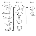
- the two dies 1a and 1b of the lower mold are adjusted to a predetermined interval, the steel sheet S is set thereon, and the tip of the punch 2 of the upper mold The punch tip 22 is pushed into a position corresponding to the distance between the two dies 1a and 1b, bending deformation is performed, and then the steel sheet S is moved by a predetermined length in the width direction and the upper die is pushed again. Repeat once.
- the steel sheet is sequentially formed from the end (A in the figure) on the one side in the width direction of the steel sheet toward the center part (C in the figure) in the width direction of the steel sheet (first half), and formed to the front of the center part in the width direction of the steel sheet.
- the steel sheet is formed in order from the end (B in the drawing) on the opposite side in the steel plate width direction toward the central portion (C in the drawing) in the steel plate width direction (second half), and finally the central portion in the steel plate width direction (in the drawing).
- an open pipe is manufactured, which is a tubular body that is formed into a cylindrical shape and whose plate ends facing each other are not welded.
- the dotted line is the position of the steel sheet S in a state where the punch 2 is not in contact with the steel sheet S.
- table rollers (not shown) are provided on the left and right sides of the dies 1a and 1b.
- the table roller can support the points B and C in a dotted line shape in the upper left diagram of FIG. 3 and can convey the steel plate S in the left-right direction in the drawing.
- Fig. 4 is a schematic diagram of an open tube.
- the open tube 3 is a tube in which a plate material as a material is formed into a cylindrical shape, and plate end portions (open seam edges) 31 a and 31 b facing each other are not welded. .
- a gap g between facing open seam edges is a seam gap.
- the tube axis direction L of the open tube 3 coincides with the longitudinal direction of the punch.
- the open pipe is then transported in the longitudinal direction of the steel pipe (the direction perpendicular to the paper surface) and sent to the next process. For this reason, after the final pass forming, which is the final bending process, the seam gap g of the open tube 3 must be wider than the thickness of the punch beam 21 that supports the punch tip 22 of the upper mold.
- the above-mentioned seam gap g of the open pipe 3 is constrained by a reduction device, and in this state, the abutted open seam edges are welded by a welding machine to obtain a straight seam welded steel pipe. If necessary, the cylindrical shape is corrected by expanding or reducing the diameter of the welded steel pipe.
- a press die provided with a mechanism for adjusting the interval between the dies of the lower die disclosed in Patent Document 1 can be used.
- the seam gap is required to be as small as possible in the final press at the bending press.
- the final press adjusts the open pipe seam gap by gradually increasing the amount of punch reduction.
- the punch press amount of the final press is increased, the seam gap amount is decreased. Conversely, when the punch press amount is small, the seam gap amount is increased.
- the punch reduction amount is increased, and even after the open seam edge contacts the punch support portion, the punch reduction amount is further increased. There is a technology to bend the open pipe.
- the yield strength of the steel sheet also affects the seam gap. This is because when the steel sheet is subjected to bending deformation, the amount of springback after the bending deformation varies depending on the yield strength of the steel sheet. For example, when the final pass press molding is performed under the same pressing conditions and the press load is completely removed, the seam gap is small when the yield strength of the steel sheet S is low, and the seam gap is high when the yield strength of the steel sheet S is high. Becomes larger.
- the seam gap tends to be large because it is usually noted that the amount of punch reduction is not excessive.
- the variation in the seam gap is also increased. If the seam gap is too large, the restraining force required to close and restrain the seam gap during welding becomes large, so that the reduction device becomes large. Further, in order to cope with variations in the seam gap, it takes a lot of time to manually adjust the reduction amount of the reduction device in the welding machine.
- the bending shape can be adjusted by adjusting the die interval of the lower mold.
- the second step adjusts the die interval of the lower mold and performs correction processing. .
- the unloaded state that is, the bending shape in the state where the spring back is generated is measured, and according to the measurement result
- the correction process as the second step is performed. Therefore, in order to reset the die interval of the lower mold, it takes time for the resetting.
- an object of the present invention is to provide a method for press forming a steel pipe with little variation in seam gap.
- the gist of the present invention is as follows.
- the open pipe as the molding material is subjected to the specific seam gap during the final press bending process.
- the method of press forming a steel pipe characterized in that the open pipe is subjected to processing of the additional reduction amount based on the above relationship from the state.
- [3] A method for manufacturing a steel pipe, characterized in that an open seam edge of an open pipe formed by the press forming method according to [1] or [2] is butted and welded.
- FIG. 1 is a diagram showing the relationship between the yield strength difference and the seam gap according to the present invention.
- FIG. 2 is a diagram showing the relationship between the yield strength difference and the seam gap according to the prior art.
- FIG. 3 is a schematic diagram for explaining a forming process in the steel pipe manufacturing process.
- FIG. 4 is a schematic diagram of an open tube.
- FIG. 5 is a schematic diagram for explaining the end bending molding process, FIG. 5A shows a set state during end bending, FIG. 5B shows a state after end bending load, and FIG. 5C shows a state after end bending unloading.
- FIG. 6 is a schematic diagram for explaining the press forming process, FIG. 6A shows a loaded state, FIG. 6B shows a state after unloading, and FIG. 6C shows a tube cross-sectional shape after press forming.
- the range from the upper limit to the lower limit of the yield strength of welded steel pipes of X80 grade is 138 MPa.
- the yield strength range is about the same in the steel plate.
- the steel sheet as a raw material is manufactured by the TMCP method, and therefore the yield strength is likely to vary due to variations in the component conditions, rolling conditions, and cooling conditions.
- end bending was performed as shown in FIG.
- 41 is an end bending lower mold
- 42 is an end bending upper mold.
- End bending was performed so that the end bending angle j (FIG. 5B) was 28 degrees during press loading in a range h (FIG. 5A) having a width of 240 mm at the end in the width direction of the steel plate.
- the bending angle k (FIG. 5C) at the end in the width direction of the steel plate after the unloading of the press load was 23 degrees.
- the punch 2 (upper die) having a radius R of the punch tip 22 shown in FIG. 6A was bent 11 times sequentially from the steel plate width direction end to the steel plate width direction.
- the molding method at this time is shown in FIG.
- the punch 2 (upper die) is composed of a punch beam 21 and a punch tip 22 and the lower die is composed of dies 1a and 1b.
- the total value of the eleven bending angles and the bending angle of the end bending are combined to obtain the entire bending angle (f in FIG. 6C) excluding the seam gap.
- the amount of bending is generally adjusted by directly controlling the amount of movement of the punch 2 with a press device.
- the amount by which the punch 2 is lowered from the state in which the punch tip 22 is in contact with the upper surface position of the steel plate (hereinafter, the amount by which the punch 2 is lowered from a certain reference point is referred to as the amount of reduction, and unless otherwise specified, the upper surface of the steel plate. Processing was performed with a fixed position).
- FIG. 2 shows the relationship between the yield strength difference, which is the difference in the yield strength of the steel plate with respect to 640 MPa, which is the standard value of the yield strength of the steel plate, and the seam gap when unloaded after pressing.
- the bending process in the intermediate process is performed by the conventional forming method, and the relationship between the yield strength difference when the amount of reduction in the final forming pass (11th) is changed and the seam gap in the unloaded state after pressing. Is shown in FIG. In FIG. 1, the result (graph b) of the prior art shown in FIG. 2 is entered for reference.
- Graph c is an example of the present invention, in which the open seam edge is further reduced by 9 mm after contacting the punch beam 21 of the upper mold so that the deformation amount in the final forming pass (the 11th time) is the same.
- the difference in seam gap in the unloaded state after pressing is as small as 20 mm, and it can be seen that a substantially uniform seam gap can be obtained regardless of the yield strength of the steel sheet.
- Graph a is an example where the open seam edge is rolled down until it touches the punch beam part of the upper mold. Compared to the prior art (graph b, constant reduction), the deviation of the seam gap in the unloaded state after pressing is smaller, but the seam gap in the unloaded state is larger than in the above-described example of the present invention. .
- both of the open seam edges are in contact with the two punch beams 21 as seam gaps as an index of a specific shape in the middle of the final press in which the amount of reduction to be further added is constant.
- the time point was adopted.
- the amount of reduction to be further added is preliminarily preformed or refer to past production results. To grasp and decide.
- the seam gap is the punch beam 21.
- the present invention is not limited to this.
- the determination that the seam gap has reached a specific value can be made by using, for example, a detector that can measure the end position of the plate at any time or a simple detector that determines that a certain position has been reached. Is possible.
- a light emitter and a light receiver are provided in the punch beam 21, and the amount of light received by the light receiver changes due to the open seam edge of the open tube blocking the route from the light projector to the light receiver.
- the position of the edge can be detected. Further, if the time point when the open seam edge comes into contact with the punch beam 21 of the upper mold 2 is detected, the position of the plate end portion is not always measured. For example, it can be realized by changing the electrical continuity state due to the contact between the open seam edge and the punch beam 21 or by providing a piezoelectric element in the planned contact portion in advance to confirm the presence or absence of the contact. .
- a signal may be sent to the reduction control device of the press forming apparatus, and the additional reduction amount determined in advance may be separately processed using this signal as a trigger.
- the additional reduction amount can be measured by measuring the movement amount of the punch 2.
- the specific seam gap is the same as the thickness of the punch beam 21, that is, when the time point when the open seam edge contacts the punch beam 21 is used as a reference, the open seam edge that contacts the punch beam 21 is the punch beam 21. It is also possible to detect the amount of sliding up 21 and control the amount of additional reduction based on the amount of sliding up.
- the open seam gap of the open pipe is continuously tack-welded using the continuous tack welding apparatus, and then the inner surface is welded and then the outer surface is welded.
- the main welding may be performed in the order of welding.
- the roundness of the steel pipe can be improved by expanding the pipe with the pipe expanding apparatus using the pipe expanding apparatus.
- the pipe expansion ratio ratio of the outer diameter change amount before and after the pipe expansion to the outer diameter of the pipe before the pipe expansion
- the tube expansion rate is preferably in the range of 0.5% to 1.2%.
- the upper die punch 2 uses a punch tip 22 having a radius of R415 mm, and the lower die 1 has an R100 mm die interval of 540 mm (the interval is two dice 1a of the lower die, 1b), and was divided into 11 times.
- the thickness of the punch beam 21 is 100 mm.
- Table 1 shows the width direction set position from the first pass to the tenth pass (distance from the center of the plate width at the center of the two dies of the lower mold) and the amount of reduction.
- the amount of reduction was determined such that when the yield strength of the steel sheet was 615 MPa, the bending at the entire circumference excluding the seam gap portion was the sum of the end bending and the 11 press formings.
- passes 1 to 5 mean the first half process
- passes 6 to 10 mean the second half process.
- Passes 1 to 5 corresponding to the first half of the process are sequentially formed from one end in the width direction of the steel sheet toward the center in the width direction of the steel sheet, and are formed to the front by the width of one press at the center in the width direction of the steel sheet.
- the passes 6 to 10 corresponding to the latter half process are sequentially formed from the opposite end of the steel plate in the width direction toward the center portion in the steel plate width direction.
- rolling is applied to the central part in the width direction of the steel sheet.
- the steel plate width direction position shown in Table 1 (the steel plate width direction position in the table is the distance in the A direction from the center C of the steel plate +, the B direction)
- the steel plate was pressed for 10 passes, and then the 11th pass was pressed to measure the seam gap in the unloaded state after pressing.
- the results (relationship between steel plate yield strength and seam gap after pressing) are shown in Table 2.
- the center of the plate width is set to be the center of the lower die, and in the present invention example, the width of the steel plate is set so that the seam gap after pressing is 125 mm with a steel plate having a yield strength of 615 MPa.
- the reduction amount which is the amount by which the punch 2 is lowered from the upper surface position of the steel plate so as to have a seam gap of 100 mm in the unloaded state after pressing with a 560 MPa steel plate having the lowest yield strength, is 48. It was 6 mm.
- Comparative Example 2 first, the oven seam edge of the open tube is rolled down until it comes into contact with the punch beam 21, and the seam gap in the unloaded state after the press is confirmed. After adjusting the interval, the reduction was repeated again.
- Comparative Example 1 although the time required for press forming is slightly shorter, in the steel plate J having the lowest yield strength, the open seam edge is in a state of sandwiching the punch beam 21, so that the forming material (open tube) is taken out. Since it was necessary to stop the line, it was difficult to adopt as industrial production.
- Comparative Example 2 although the shape is stable, the required time is 1.4 times that of the present invention example, and the production efficiency is inferior.
- the steel pipe press forming method and the steel pipe manufacturing method of the present invention are not limited to the manufacturing of large-diameter and thick-walled steel pipes, and can be applied to all methods of manufacturing steel pipes by performing a three-point bending press. it can.
Abstract
Priority Applications (5)
| Application Number | Priority Date | Filing Date | Title |
|---|---|---|---|
| RU2015155551A RU2648813C2 (ru) | 2013-05-30 | 2013-05-30 | Способ формовки стальной трубы и способ производства стальной трубы |
| CN201380077095.0A CN105246609B (zh) | 2013-05-30 | 2013-05-30 | 钢管的冲压成形方法及钢管的制造方法 |
| PCT/JP2013/003435 WO2014192043A1 (fr) | 2013-05-30 | 2013-05-30 | Procédé de moulage par pressage d'un tuyau d'acier et procédé de fabrication de ce dernier |
| EP13885877.4A EP3006129B1 (fr) | 2013-05-30 | 2013-05-30 | Procédé de moulage par pressage d'un tuyau d'acier et procédé de fabrication de ce dernier |
| JP2015519499A JP5967302B2 (ja) | 2013-05-30 | 2013-05-30 | 鋼管のプレス成形方法および鋼管の製造方法 |
Applications Claiming Priority (1)
| Application Number | Priority Date | Filing Date | Title |
|---|---|---|---|
| PCT/JP2013/003435 WO2014192043A1 (fr) | 2013-05-30 | 2013-05-30 | Procédé de moulage par pressage d'un tuyau d'acier et procédé de fabrication de ce dernier |
Publications (1)
| Publication Number | Publication Date |
|---|---|
| WO2014192043A1 true WO2014192043A1 (fr) | 2014-12-04 |
Family
ID=51988128
Family Applications (1)
| Application Number | Title | Priority Date | Filing Date |
|---|---|---|---|
| PCT/JP2013/003435 WO2014192043A1 (fr) | 2013-05-30 | 2013-05-30 | Procédé de moulage par pressage d'un tuyau d'acier et procédé de fabrication de ce dernier |
Country Status (5)
| Country | Link |
|---|---|
| EP (1) | EP3006129B1 (fr) |
| JP (1) | JP5967302B2 (fr) |
| CN (1) | CN105246609B (fr) |
| RU (1) | RU2648813C2 (fr) |
| WO (1) | WO2014192043A1 (fr) |
Cited By (3)
| Publication number | Priority date | Publication date | Assignee | Title |
|---|---|---|---|---|
| WO2018168563A1 (fr) | 2017-03-15 | 2018-09-20 | Jfeスチール株式会社 | Moule de presse et procédé de fabrication de tuyau en acier |
| WO2020054051A1 (fr) | 2018-09-14 | 2020-03-19 | Jfeスチール株式会社 | Procédé de fabrication de tuyau en acier et matrice de presse |
| JP2021524382A (ja) * | 2018-07-09 | 2021-09-13 | エス・エム・エス・グループ・ゲゼルシャフト・ミト・ベシュレンクテル・ハフツング | Jco成形プレスの拡張された制御 |
Families Citing this family (2)
| Publication number | Priority date | Publication date | Assignee | Title |
|---|---|---|---|---|
| CN108994120A (zh) * | 2018-08-01 | 2018-12-14 | 上海锆卓船舶设计有限公司 | 适用超高强度、超厚钢板的小直径圆筒的卷制方法及系统 |
| JP7108523B2 (ja) * | 2018-11-27 | 2022-07-28 | Hoya株式会社 | プレス成形装置、プレス成形方法及びプレス成形プログラム |
Citations (4)
| Publication number | Priority date | Publication date | Assignee | Title |
|---|---|---|---|---|
| JPH10166059A (ja) * | 1996-12-06 | 1998-06-23 | Mitsubishi Heavy Ind Ltd | 板の曲げ加工方法 |
| JPH11129031A (ja) | 1997-10-29 | 1999-05-18 | Mitsubishi Heavy Ind Ltd | プレス成形金型 |
| JP2003154411A (ja) * | 2001-09-10 | 2003-05-27 | Chuo Spring Co Ltd | プレス装置とプレス装置のプレス型 |
| JP2012170977A (ja) * | 2011-02-21 | 2012-09-10 | Jfe Steel Corp | 鋼管の製造方法 |
Family Cites Families (9)
| Publication number | Priority date | Publication date | Assignee | Title |
|---|---|---|---|---|
| SU366009A1 (ru) * | 1971-04-30 | 1973-01-16 | Научно исследовательский институт асбестоцементной промышленности | Стержневая мельница |
| FI74414C (fi) * | 1980-08-18 | 1988-02-08 | Sl Tuotanto Oy | Anordning foer framstaellning av ett metallroer. |
| TW449509B (en) * | 1998-11-04 | 2001-08-11 | Kawasaki Steel Co | Bending rolls, and pipe formed thereby |
| CN1738687A (zh) * | 2003-01-20 | 2006-02-22 | 新日本制铁株式会社 | 金属箔管及其制造方法与制造装置 |
| JP5511760B2 (ja) * | 2005-07-04 | 2014-06-04 | ホシザキ電機株式会社 | ショーケース |
| WO2012092909A1 (fr) * | 2011-01-07 | 2012-07-12 | Technische Universität Dortmund | Procédé pour la transformation incrémentielle de structures en tôle, en particulier pour la transformation de tubes ou similaires |
| DE102011009660B4 (de) * | 2011-01-27 | 2013-05-29 | Sms Meer Gmbh | Vorrichtung und Verfahren zum Umformen von Flachprodukten in Schlitzrohre oder Rohrvorprodukte |
| EP2529849B1 (fr) * | 2011-05-31 | 2021-03-10 | SMS group GmbH | Dispositif et procédé de fabrication de tuyaux fendus à partir de plaques de tôle |
| DE102011053676B4 (de) * | 2011-09-16 | 2016-09-08 | EISENBAU KRäMER GMBH | Rohrbiegemaschine |
-
2013
- 2013-05-30 EP EP13885877.4A patent/EP3006129B1/fr active Active
- 2013-05-30 JP JP2015519499A patent/JP5967302B2/ja active Active
- 2013-05-30 RU RU2015155551A patent/RU2648813C2/ru active
- 2013-05-30 WO PCT/JP2013/003435 patent/WO2014192043A1/fr active Application Filing
- 2013-05-30 CN CN201380077095.0A patent/CN105246609B/zh active Active
Patent Citations (4)
| Publication number | Priority date | Publication date | Assignee | Title |
|---|---|---|---|---|
| JPH10166059A (ja) * | 1996-12-06 | 1998-06-23 | Mitsubishi Heavy Ind Ltd | 板の曲げ加工方法 |
| JPH11129031A (ja) | 1997-10-29 | 1999-05-18 | Mitsubishi Heavy Ind Ltd | プレス成形金型 |
| JP2003154411A (ja) * | 2001-09-10 | 2003-05-27 | Chuo Spring Co Ltd | プレス装置とプレス装置のプレス型 |
| JP2012170977A (ja) * | 2011-02-21 | 2012-09-10 | Jfe Steel Corp | 鋼管の製造方法 |
Cited By (6)
| Publication number | Priority date | Publication date | Assignee | Title |
|---|---|---|---|---|
| WO2018168563A1 (fr) | 2017-03-15 | 2018-09-20 | Jfeスチール株式会社 | Moule de presse et procédé de fabrication de tuyau en acier |
| KR20190124769A (ko) | 2017-03-15 | 2019-11-05 | 제이에프이 스틸 가부시키가이샤 | 프레스 금형 및 강관의 제조 방법 |
| JP2021524382A (ja) * | 2018-07-09 | 2021-09-13 | エス・エム・エス・グループ・ゲゼルシャフト・ミト・ベシュレンクテル・ハフツング | Jco成形プレスの拡張された制御 |
| JP7185007B2 (ja) | 2018-07-09 | 2022-12-06 | エス・エム・エス・グループ・ゲゼルシャフト・ミト・ベシュレンクテル・ハフツング | Jco成形プレスの拡張された制御 |
| WO2020054051A1 (fr) | 2018-09-14 | 2020-03-19 | Jfeスチール株式会社 | Procédé de fabrication de tuyau en acier et matrice de presse |
| KR20210041032A (ko) | 2018-09-14 | 2021-04-14 | 제이에프이 스틸 가부시키가이샤 | 강관의 제조 방법 및 프레스 금형 |
Also Published As
| Publication number | Publication date |
|---|---|
| EP3006129B1 (fr) | 2019-07-10 |
| RU2015155551A (ru) | 2017-07-06 |
| CN105246609B (zh) | 2017-03-15 |
| EP3006129A1 (fr) | 2016-04-13 |
| JPWO2014192043A1 (ja) | 2017-02-23 |
| RU2648813C2 (ru) | 2018-03-28 |
| EP3006129A4 (fr) | 2016-06-22 |
| JP5967302B2 (ja) | 2016-08-10 |
| CN105246609A (zh) | 2016-01-13 |
Similar Documents
| Publication | Publication Date | Title |
|---|---|---|
| JP5967302B2 (ja) | 鋼管のプレス成形方法および鋼管の製造方法 | |
| KR101945091B1 (ko) | 벤딩 프레스 성형용 금형 | |
| JP6015997B1 (ja) | 鋼管の製造方法及びその方法に使用するプレス金型 | |
| JP6070967B2 (ja) | 溶接鋼管の製造方法 | |
| JP6607102B2 (ja) | 溶接鋼管の成形方法および成形装置並びに溶接鋼管の製造方法および製造設備 | |
| CN110461488B (zh) | 冲压模具及钢管的制造方法 | |
| KR101712885B1 (ko) | 강관의 제조 방법 | |
| WO2014188468A1 (fr) | Dispositif de presse à cintrer, procédé de presse à cintrer, dispositif de production de tube d'acier, et procédé de production de tube d'acier | |
| JP5135540B2 (ja) | 鋼管製造設備及び鋼管製造方法 | |
| JP6028931B2 (ja) | 鋼管の製造方法およびその製造装置 | |
| JP6566231B1 (ja) | 鋼板の端曲げ方法および装置並びに鋼管の製造方法および設備 | |
| EP3778050B1 (fr) | Procédé et dispositif pour cintrer le flanc d'une plaque d'acier, et procédé et équipement de fabrication de tuyau en acier | |
| JP6566232B1 (ja) | 鋼板の端曲げ方法および装置並びに鋼管の製造方法および設備 | |
| JP6282006B2 (ja) | 鋼管の製造方法およびその製造装置 | |
| JP6272717B2 (ja) | 板材のベンディングプレス成形方法及びそのベンディングプレス成形方法を用いた鋼管の製造方法 | |
| JP3990761B2 (ja) | 真円度の優れた溶接管の製造方法 | |
| EP3778051B1 (fr) | Procédé et dispositif de pliage d'un bord d'une plaque d'acier et procédé et installation pour la fabrication de tuyau en acier | |
| JP2004141936A (ja) | Uoe鋼管の製造方法 | |
| KR20230015974A (ko) | 강관의 진원도 예측 방법, 강관의 진원도 제어 방법, 강관의 제조 방법, 강관의 진원도 예측 모델의 생성 방법, 및 강관의 진원도 예측 장치 | |
| JP2000117325A (ja) | 断面多角形閉状態の管の製造方法及びそのための装置 | |
| JPS5897423A (ja) | 大径角形鋼管の製造装置 |
Legal Events
| Date | Code | Title | Description |
|---|---|---|---|
| 121 | Ep: the epo has been informed by wipo that ep was designated in this application |
Ref document number: 13885877 Country of ref document: EP Kind code of ref document: A1 |
|
| ENP | Entry into the national phase |
Ref document number: 2015519499 Country of ref document: JP Kind code of ref document: A |
|
| WWE | Wipo information: entry into national phase |
Ref document number: 2013885877 Country of ref document: EP |
|
| WWE | Wipo information: entry into national phase |
Ref document number: P1585/2015 Country of ref document: AE |
|
| NENP | Non-entry into the national phase |
Ref country code: DE |
|
| ENP | Entry into the national phase |
Ref document number: 2015155551 Country of ref document: RU Kind code of ref document: A |