WO2014189134A1 - 核医学診断装置および核医学画像生成方法 - Google Patents
核医学診断装置および核医学画像生成方法 Download PDFInfo
- Publication number
- WO2014189134A1 WO2014189134A1 PCT/JP2014/063716 JP2014063716W WO2014189134A1 WO 2014189134 A1 WO2014189134 A1 WO 2014189134A1 JP 2014063716 W JP2014063716 W JP 2014063716W WO 2014189134 A1 WO2014189134 A1 WO 2014189134A1
- Authority
- WO
- WIPO (PCT)
- Prior art keywords
- image
- time
- coincidence
- filter
- nuclear medicine
- Prior art date
- Legal status (The legal status is an assumption and is not a legal conclusion. Google has not performed a legal analysis and makes no representation as to the accuracy of the status listed.)
- Ceased
Links
Images




Classifications
-
- A—HUMAN NECESSITIES
- A61—MEDICAL OR VETERINARY SCIENCE; HYGIENE
- A61B—DIAGNOSIS; SURGERY; IDENTIFICATION
- A61B6/00—Apparatus or devices for radiation diagnosis; Apparatus or devices for radiation diagnosis combined with radiation therapy equipment
- A61B6/02—Arrangements for diagnosis sequentially in different planes; Stereoscopic radiation diagnosis
- A61B6/03—Computed tomography [CT]
- A61B6/037—Emission tomography
-
- A—HUMAN NECESSITIES
- A61—MEDICAL OR VETERINARY SCIENCE; HYGIENE
- A61B—DIAGNOSIS; SURGERY; IDENTIFICATION
- A61B6/00—Apparatus or devices for radiation diagnosis; Apparatus or devices for radiation diagnosis combined with radiation therapy equipment
- A61B6/52—Devices using data or image processing specially adapted for radiation diagnosis
- A61B6/5205—Devices using data or image processing specially adapted for radiation diagnosis involving processing of raw data to produce diagnostic data
-
- G—PHYSICS
- G01—MEASURING; TESTING
- G01T—MEASUREMENT OF NUCLEAR OR X-RADIATION
- G01T1/00—Measuring X-radiation, gamma radiation, corpuscular radiation, or cosmic radiation
- G01T1/29—Measurement performed on radiation beams, e.g. position or section of the beam; Measurement of spatial distribution of radiation
- G01T1/2914—Measurement of spatial distribution of radiation
- G01T1/2985—In depth localisation, e.g. using positron emitters; Tomographic imaging (longitudinal and transverse section imaging; apparatus for radiation diagnosis sequentially in different planes, steroscopic radiation diagnosis)
-
- A—HUMAN NECESSITIES
- A61—MEDICAL OR VETERINARY SCIENCE; HYGIENE
- A61B—DIAGNOSIS; SURGERY; IDENTIFICATION
- A61B6/00—Apparatus or devices for radiation diagnosis; Apparatus or devices for radiation diagnosis combined with radiation therapy equipment
- A61B6/46—Arrangements for interfacing with the operator or the patient
- A61B6/461—Displaying means of special interest
Definitions
- Embodiments described herein relate generally to a nuclear medicine diagnostic apparatus and a nuclear medicine image generation method.
- Nuclear medicine diagnostic devices such as PET (Positron Emission Tomography) devices, drugs (blood flow markers, tracers) containing radioisotopes (hereinafter referred to as RI) are selectively taken into specific tissues and organs in the body. Utilizing this property, gamma rays emitted from RI distributed in the living body are detected by a gamma ray detector disposed outside the living body. The detection result of gamma rays is used for generation of nuclear medicine images by imaging the dose distribution of gamma rays, diagnosis of functions of internal organs and the like.
- PET Positron Emission Tomography
- drugs blood flow markers, tracers
- RI radioisotopes
- TOF-PET a TOF-PET system
- TOF Time of Flight
- a position filter such as a Gaussian filter is applied to each occurrence position information (hereinafter referred to as position information) of the pair annihilation event obtained from the coincidence counting information.
- position information occurrence position information
- the occurrence position of the pair annihilation event is blurred by the position filter, so even if the nuclear medicine image is reconstructed with only one coincidence information, the user can accurately grasp the occurrence position of the pair annihilation event from this image. It ’s difficult.
- the scan method is a mode that scans while gradually shifting the relative positional relationship between the bed and the detector (hereinafter referred to as continuous scan mode)
- the coincidence count information is accumulated until the scan is completed, and the scan is completed.
- a method of reconstructing a nuclear medicine image based on the coincidence information accumulated later can be considered.
- the scan mode when the scan at one scan position is completed, one of the bed or the detector is moved to the next scan position and the next scan is repeated (hereinafter referred to as multi-bed scan mode).
- multi-bed scan mode a method of reconstructing a nuclear medicine image based on the accumulated coincidence information every time scanning at one scan position is completed can be considered.
- FIG. 1 is a block diagram showing an example of a nuclear medicine diagnostic apparatus according to a first embodiment of the present invention.
- the schematic block diagram which shows the structural example of the function implementation part by CPU of the control part which concerns on 1st Embodiment.
- (3A) is an explanatory view showing an example of a real-time image when it is assumed that the time resolution of the TOF-PET apparatus is ideally reduced as much as possible
- (3B) is a time resolution of the TOF-PET apparatus having a finite value. Explanatory drawing which shows an example of the real-time image in the case.
- Explanatory drawing which shows an example of the utilization method of the memory for real-time images, the memory for filter images, and the memory for display images when a real-time image and a filter image are superimposed and displayed on a display part.
- Explanatory drawing which shows an example of the utilization method of the memory for real-time images, the memory for filter images, and the memory for display images when only a filter image is displayed on a display part.
- the flowchart which shows the procedure at the time of producing
- the schematic block diagram which shows the structural example of the function implementation part by CPU of the control part which concerns on 2nd Embodiment.
- the flowchart which shows the procedure at the time of producing
- the schematic block diagram which shows the structural example of the function implementation part by CPU of the control part which concerns on 3rd Embodiment.
- the flowchart which shows the procedure at the time of producing
- a nuclear medicine diagnosis apparatus is based on output data of a plurality of detectors that detect gamma rays emitted from a radioisotope administered to a subject.
- a coincidence count data acquisition unit for acquiring coincidence count data indicating the position where each coincidence pair annihilation event is generated, and filtering the coincidence count data each time a condition necessary for the filter process is satisfied.
- a filter image generation unit that generates a filter image.
- FIG. 1 is a block diagram showing an example of a nuclear medicine diagnostic apparatus according to the first embodiment of the present invention.
- a TOF-PET apparatus is used as the nuclear medicine diagnostic apparatus according to the present invention.
- the nuclear medicine diagnosis apparatus performs a scan in a multi-bed scan mode in which the top plate is moved to the next scan position and the next scan is repeated when the scan at one scan position is completed.
- the nuclear medicine diagnostic apparatus 10 includes a scanner device 11 and an image processing device 12.
- the scanner device 11 includes a top plate 21, a top plate driving device 22, a plurality of detectors 23, a detector cover 24, and a data collection unit 25.
- the top plate 21 is configured such that a patient (subject) O can be placed thereon.
- the top plate driving device 22 is controlled by the image processing device 12 to move the top plate 21 up and down. Further, the top plate driving device 22 is controlled by the image processing device 12 to transfer the top plate 21 along the long axis direction of the top plate 21 to the opening of the central portion of the detector cover 24.
- the detector 23 is a detector that detects gamma rays emitted from a radioisotope contained in a medicine such as FDG (fluorodeoxyglucose) and administered to the patient O.
- a scintillator type detector or a semiconductor type detector may be used.
- the detector 23 detects a collimator for defining the incident angle of the gamma ray, a scintillator that emits an instantaneous flash when the collimated gamma ray is incident, and light emitted from the scintillator.
- a plurality of photomultiplier tubes arranged in a two-dimensional manner, and an electronic circuit for a scintillator.
- the scintillator is made of, for example, thallium activated sodium iodide NaI (Tl).
- the scintillator electronic circuit has information on the incident position of gamma rays in a detection plane constituted by a plurality of photomultiplier tubes based on the output of the plurality of photomultiplier tubes every time an event in which gamma rays are incident occurs. (Position information) and intensity information are generated and output to the data collection unit 25.
- the detector 23 includes a collimator, a plurality of gamma ray detecting semiconductor elements (hereinafter referred to as semiconductor elements) arranged in two dimensions for detecting collimated gamma rays, and a semiconductor detector.
- semiconductor elements a plurality of gamma ray detecting semiconductor elements (hereinafter referred to as semiconductor elements) arranged in two dimensions for detecting collimated gamma rays, and a semiconductor detector.
- semiconductor elements a plurality of gamma ray detecting semiconductor elements
- the semiconductor element is made of, for example, CdTe or CdZnTe (CZT).
- the semiconductor electronic circuit generates position information and intensity information based on the output of the semiconductor element and outputs them to the data collecting unit 25 every time an event in which gamma rays are incident occurs.
- the plurality of detectors 23 are arranged in the detector cover 24 in a hexagonal shape or a circular shape so as to surround the periphery of the patient O, for example.
- the arrangement of the plurality of detectors 23 is not limited to the ring arrangement type.
- the plurality of detectors 23 arranged on a flat plate can be rotated around the patient O while the two detectors 23 are opposed to each other with the patient O interposed therebetween. You may arrange
- the plurality of detectors 23 may be arranged in a multilayer ring so that images between adjacent layers can be acquired.
- the data collection unit 25 collects the outputs of the plurality of detectors 23 in the form of list mode, photomultiplier tube map image data, or the like.
- list mode gamma ray detection position information, intensity (energy) information, information indicating the relative position between the detector 23 and the patient O (such as the position and angle of the detector 23), and the detection time of the gamma ray are gamma ray pair annihilation. Collected for each event.
- the data collecting unit 25 may collect the outputs of the plurality of detectors 23 in the form of coincidence list mode data.
- the coincidence list mode data includes a gamma ray incident time difference (difference in detection time of annihilation gamma rays) within a predetermined time window width (for example, within 1 ns) and the incidence of each of two annihilation gamma rays in the list mode data. A combination in which both energies are within a predetermined energy window width is extracted.
- coincidence pair annihilation event the pair annihilation event corresponding to each of the extracted combinations is referred to as a coincidence pair annihilation event (simultaneous counting event). Further, the data indicating the occurrence position of the coincidence pair annihilation event obtained from the coincidence list mode data is referred to as coincidence count data.
- a position filter such as a Gaussian filter is applied to the occurrence position of the coincidence pair annihilation event obtained from the coincidence list mode data.
- the position filter is applied in consideration of an error in time of arrival (TOF) due to the time resolution of the detector system (for example, 500 psec). By blurring the position, the position information can be corrected to take account of the TOF measurement error.
- TOF time of arrival
- the coordinate point of the occurrence position of the coincidence event is obtained from the difference between the measurement times of both detectors that have detected the coincidence event, and the distribution is blurred along with the Gaussian function corresponding to the time resolution of the detector along the LOR. Is position information.
- the occurrence position of the pair annihilation event indicated by the coincidence count data is given as a line segment having a predetermined length along LOR (Line of Response).
- the image processing apparatus 12 includes a control unit 31, a display unit 32, an input unit 33, and a storage unit 34, as shown in FIG.
- the control unit 31 includes a storage medium such as a CPU, a RAM, and a ROM, and controls the processing operation of the image processing apparatus 12 according to a program stored in the storage medium.
- the CPU of the control unit 31 loads a nuclear medicine image generation program stored in a storage medium such as a ROM and data necessary for executing the program into the RAM, and determines the occurrence position of the pair annihilation event according to the program.
- a process for generating a nuclear medicine image that can be grasped by the user in real time is executed.
- the RAM of the control unit 31 provides a work area for temporarily storing programs and data executed by the CPU.
- the storage medium including the ROM of the control unit 31 stores a startup program for the image processing apparatus 12, a nuclear medicine image generation program, and various data necessary for executing these programs.
- a storage medium such as a ROM has a configuration including a recording medium readable by a CPU, such as a magnetic or optical recording medium or a semiconductor memory, and a part of programs and data in the storage medium. Or you may comprise so that all may be downloaded via an electronic network.
- the display unit 32 is configured by a general display output device such as a liquid crystal display or an OLED (Organic Light Emitting Diode) display, and displays various information such as a real-time image and a filter image under the control of the control unit 31.
- a general display output device such as a liquid crystal display or an OLED (Organic Light Emitting Diode) display
- OLED Organic Light Emitting Diode
- the input unit 33 is configured by a general input device such as a keyboard, a touch panel, or a numeric keypad, and outputs an operation input signal corresponding to a user operation to the control unit 31.
- a general input device such as a keyboard, a touch panel, or a numeric keypad
- the storage unit 34 has a configuration that includes a CPU-readable recording medium such as a magnetic or optical recording medium or a semiconductor memory, and some or all of the programs and data in the storage medium are stored in an electronic network. You may comprise so that it may be downloaded via.
- the storage unit 34 is controlled by the control unit 31 to store coincidence list mode data, a real-time image generated based on the coincidence list mode data, a filter image, and the like.
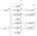
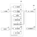
- FIG. 2 is a schematic block diagram illustrating a configuration example of a function realization unit by the CPU of the control unit 31 according to the first embodiment.
- this function realization part may be comprised by hardware logics, such as a circuit, without using CPU.
- the CPU of the control unit 31 performs at least a scan control unit 41, a coincidence list mode data acquisition unit 42 as a coincidence count data acquisition unit, a real-time image generation unit 43, and filter control by a nuclear medicine image generation program.
- Each unit 41-47 uses a required work area of the RAM as a temporary storage location for data.
- the storage unit 34 includes a raw data storage unit 51, a real-time image memory 52, a filter image memory 53, and a display image memory 54.
- the raw data storage unit 51 and the memories 52-54 may be physically independent storage media, or two or more (for example, the real-time image memory 52) for the memory space of the same storage medium.
- two of the filter image memory 53 may be virtually allocated.
- the scan control unit 41 receives a scan plan execution instruction from the user via the input unit 33, and controls the scanner device 11 based on the scan plan to execute a scan. As a result, information on the gamma rays emitted from the patient O is given from the scanner device 11 to the coincidence list mode data acquisition unit 42 via the data collection unit 25.
- the scan plan is a scan plan according to the multi-bed scan mode in which when the scan at one scan position is completed, the top plate 21 is moved to the next scan position and the next scan is repeated. .
- the coincidence list mode data acquisition unit 42 serving as the coincidence data acquisition unit obtains the coincidence list mode data based on the raw data received from the data collection unit 25. Created and stored in the raw data storage unit 51.
- the coincidence list mode data acquisition unit 42 causes the raw data storage unit 51 to store the raw data as it is. Note that even if the raw data received from the data collection unit 25 is not coincidence list mode data, it is stored in the raw data storage unit 51 as it is, and before the real-time image generation described below is performed (the coincidence list mode data is stored in the raw data storage unit 51). May be converted into coincidence list mode data.
- the coincidence list mode data stored in the raw data storage unit 51 by the coincidence list mode data acquisition unit 42 is also appropriately referred to as raw data, as is the output data of the plurality of detectors 23 received from the data collection unit 25. Shall.
- the data collection unit 25 collects the outputs of the plurality of detectors 23 for each gamma ray pair annihilation event and supplies the collected data to the control unit 31. For this reason, the coincidence list mode data acquisition unit 42 can update the coincidence list mode data for each pair-annihilation event counted simultaneously. Further, the coincidence list mode data acquisition unit 42 can acquire, for each coincidence event, data indicating the occurrence position of the coincidence event (coincidence data) based on the coincidence list mode data.
- the real-time image generation unit 43 detects a coincidence event every time the coincidence list mode data acquisition unit 42 acquires coincidence count data (data indicating the occurrence position of a coincidence counter-annihilation event (coincidence event)). Each time, an image (hereinafter referred to as a real-time image) on which an image indicating the occurrence position of the coincidence event is superimposed is generated and stored in the real-time image memory 52.
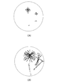
- FIG. 3 is an explanatory view showing an example of a real-time image when it is assumed that the time resolution of the TOF-PET apparatus is ideally reduced as much as possible.
- (3B) is an example of the time resolution of the TOF-PET apparatus. It is explanatory drawing which shows an example of the real-time image in the case of having a finite value.
- each of the images showing the coincidence event occurrence position is infinitely close to a point as shown in FIG. 3 (3A).
- the real-time image is an image in which these points are superimposed.
- the time resolution of an actual TOF-PET apparatus has a finite value (for example, 500 ps).
- the real-time image generated by the real-time image generation unit 43 according to the present embodiment is such that, as shown in FIG.
- the image is represented as a line segment having a predetermined length along (Line of Response).
- the real-time image according to the present embodiment is an image with a low spatial resolution of the occurrence position of the coincidence event, and it is difficult for the user to accurately determine the occurrence position of the coincidence event. It can be said that it is an image capable of grasping the occurrence position of. Therefore, according to this real-time image, the user is more real-time than in the case of reconstructing a nuclear medicine image based on the coincidence count information accumulated every time scanning at one scan position is completed in the multi-bed scan mode. In addition, the occurrence position of the coincidence event can be grasped.
- the filter control unit 44 determines whether or not the conditions necessary for the filter processing are satisfied. When the filter control unit 44 determines that the conditions necessary for the filter processing are satisfied, the filter control unit 44 generates the coincidence count data (or accumulates the coincidence count data). The filter image generation unit 45 is instructed to generate a filter image by performing a filtering process on real-time image data that is an image).
- a filter process used for filtered back projection can be used.
- Various types of filter processing used for filtered back projection are known, such as filter processing using a Shepp & Logan filter and 2D or 3D filter processing using a Ramp filter, and any of these can be applied. I can do things.
- the filter control unit 44 stores the number of coincidence events stored in the raw data storage unit 51 (simultaneous corresponding to each of the pair annihilation events). The number of pieces of count data) is acquired, and the filter image generation unit 45 may be instructed to generate a filter image every time a predetermined number is accumulated (for example, every 20 counts).
- T1 predetermined time
- the display control unit 46 develops at least one of the real-time image and the filter image in the display image memory 54 and causes the display unit 32 to display the image. That is, on the display unit 32, only the real-time image may be displayed, only the filter image may be displayed, or both may be displayed in a superimposed manner, or both may be displayed side by side in separate windows. May be.
- the end determination unit 47 controls the scanner device 11 via the scan control unit 41 so as to execute the scan at the next scan position when the scan at one scan position is completed. Further, the end determination unit 47 stops the operation of the scanner device 11 via the scan control unit 41 when the scans at all the scan positions are completed.
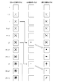
- FIG. 4 is an explanatory diagram illustrating an example of a method of using the real-time image memory 52, the filter image memory 53, and the display image memory 54 when the real-time image and the filter image are superimposed and displayed on the display unit 32. .
- the real-time image generation unit 43 superimposes one line-segment image indicating the generation position of the coincidence event on the real-time image memory 52 one by one every time a coincidence event is detected.
- the real-time image will be updated.
- a plurality of filter image generation units 45 may be provided. In this case, since filter image generation processing can be performed simultaneously in parallel, T1 ⁇ T may be satisfied. For example, when two filter image generation units 45 are provided, T1 ⁇ T / 2 may be satisfied.
- T1 + T for example, 2T1, etc.
- the display control unit 46 sequentially develops the contents in the display image memory 54. Further, when the filter image in the filter image memory 53 is updated, the display control unit 46 expands the contents in the display image memory 54. At this time, the real-time image previously developed in the display image memory 54 may be deleted, or the filter image may be superimposed while being left as it is.
- the real time image is erased every time the filter image is developed in the display image memory 54, and every time the real time image memory 52 is updated until the next filter image is updated.
- the filter image Since the filter image has higher spatial resolution than the real-time image, it is possible to accurately display the occurrence position of the coincidence event. For this reason, the user can confirm an image with better visibility. That is, the user can see an image with better visibility by displaying the filter image as compared with the case where only the real-time image is displayed.
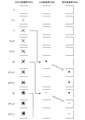
- FIG. 5 is an explanatory diagram showing an example of a method of using the real-time image memory 52, the filter image memory 53, and the display image memory 54 when only the filter image is displayed on the display unit 32.
- the display control unit 46 may develop only the filter image in the display image memory 54 as shown in FIG.
- the generation cycle of the filter image is time T1 ⁇ T, and this time T1 is shorter than the time required for scanning at one scan position. For this reason, even when only the filter image is displayed, the user reconstructs a nuclear medicine image based on the coincidence count information accumulated every time scanning is completed at one scan position in the multi-bed scan mode. Compared to the case, a filter image with a higher spatial resolution can be confirmed in real time, and the occurrence position of the coincidence event can be accurately grasped in real time.
- T1 can be further shortened.
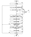
- FIG. 6 is a flowchart showing a procedure when the CPU of the control unit 31 shown in FIG. 1 generates a nuclear medicine image in which the user can grasp the occurrence position of the pair annihilation event in real time.
- This procedure starts when the patient O who has received a drug such as FDG is placed on the top board 21.
- a drug such as FDG
- FIG. 4 an example (see FIG. 4) in which a real-time image and a filter image are superimposed and displayed on the display unit 32 will be described.
- step S1 the scan control unit 41 receives an instruction to execute a scan plan in accordance with the multi-bed scan mode from the user via the input unit 33, and controls the scanner device 11 based on the scan plan. Start scanning.
- step S ⁇ b> 2 the coincidence list mode data acquisition unit 42 receives output data (raw data) from the plurality of detectors 23 from the data collection unit 25.
- step S3 the coincidence list mode data acquisition unit 42 determines whether or not the raw data received from the data collection unit 25 is coincidence list mode data. If it is not coincidence list mode data, the process proceeds to step S4. On the other hand, if it is coincidence list mode data, the process proceeds to step S5.
- step S4 the coincidence list mode data acquisition unit 42 creates coincidence list mode data based on the raw data received from the data collection unit 25.
- the coincidence list mode data acquisition unit 42 stores the coincidence list mode data (raw data) in the raw data storage unit 51.
- the raw data may not be coincidence list mode data, but may be stored in the raw data storage unit 51 as it is.
- the coincidence list mode data is created after the raw data is saved in step S6. It may be performed before real-time image generation.
- the coincidence list mode data acquisition unit 42 performs the simultaneous counting for each pair annihilation event.
- the coincidence list mode data can be updated. For this reason, steps S2-S5 may be executed concurrently with the following steps S6 and after.
- step S6 the real-time image generation unit 43 stores the coincidence event in the real-time image memory 52 every time the coincidence list mode data acquisition unit 42 obtains the coincidence count data, that is, every time a coincidence event is detected.
- a real-time image is generated by superimposing line segment images indicating the generation positions one by one, and is stored in the real-time image memory 52.
- step S 7 the display control unit 46 updates the image displayed on the display unit 32 by updating the contents of the display image memory 54 in accordance with the update of the real-time image memory 52.
- step S8 the filter control unit 44 determines whether or not a condition necessary for the filter processing used for the filtered back projection is satisfied. For example, the filter control unit 44 determines whether or not the period of time T required for the filter processing has arrived. If the conditions necessary for the filter processing are satisfied, the filter control unit 44 instructs the filter image generation unit 45 to generate a filter image, and the process proceeds to step S9. On the other hand, if the conditions necessary for the filter processing are not satisfied, the process returns to step S2.
- step S9 the filter image generation unit 45 performs filter processing on the coincidence count data (or real-time image data that is an image generated by accumulating the coincidence count data) to generate a filter image. And stored in the filter image memory 53.
- step S ⁇ b> 10 the display control unit 46 updates the image displayed on the display unit 32 by updating the contents of the display image memory 54 in accordance with the update of the filter image memory 53.
- step S11 the end determination unit 47 determines whether or not the scan at the current scan position has ended. If not completed, the process returns to step S2.
- step S12 the end determination unit 47 further determines whether the scan at all the scan positions is completed. If not completed, the end determination unit 47 controls the scanner device 11 via the scan control unit 41 to execute the scan at the next scan position in step S13, and returns to step S2. On the other hand, when the scans at all the scan positions are completed, the end determination unit 47 stops the operation of the scanner device 11 via the scan control unit 41, and the series of procedures is completed.
- the nuclear medicine diagnostic apparatus 10 can display at least one of a real-time image and a filter image on the display unit 32 in the multi-bed scan mode. For example, when displaying a real-time image, it is possible to display the real-time image on the display unit 32 while updating the real-time image at a cycle much shorter than the time required to complete scanning at one scan position in the multi-bed scan mode. it can. For this reason, the user can generate a coincidence event in real time as compared with the case where the nuclear medicine image is reconstructed based on the coincidence information accumulated every time the scan at one scan position is completed in the multi-bed scan mode. The position can be grasped.
- the filter image having a higher spatial resolution than that of the real-time image is updated at a cycle T1 that is much shorter than the time required to complete scanning at one scan position in the multi-bed scan mode. It can be displayed on the display unit 32. For this reason, the user can generate a coincidence event in real time as compared with the case where the nuclear medicine image is reconstructed based on the coincidence information accumulated every time the scan at one scan position is completed in the multi-bed scan mode. The position can be grasped. Further, by displaying the filter image as compared with the case where only the real-time image is displayed, the user can grasp the occurrence position of the coincidence event more accurately based on the filter image having excellent spatial resolution.
- the nuclear medicine diagnosis apparatus shown in the second embodiment is characterized in that the scan is performed in the continuous scan mode in which the entire imaging target region of the subject is scanned while gradually shifting the relative positional relationship between the bed and the detector 23. Different from the nuclear medicine diagnostic apparatus according to the embodiment.
- FIG. 7 is a schematic block diagram illustrating a configuration example of a function realization unit by the CPU of the control unit 31A according to the second embodiment.
- the data collection section 25A, the configuration of the control section 31A, and the configuration of the storage section 34A are the data collection section 25 and the control section of the nuclear medicine diagnosis apparatus 10 shown in the first embodiment. 31 and the storage unit 34. Since other configurations and operations are not substantially different from those of the nuclear medicine diagnostic apparatus 10 shown in FIG. 1, the same components are denoted by the same reference numerals and description thereof is omitted.
- the CPU of the control unit 31A performs at least a scan control unit 41A, a coincidence list mode data acquisition unit 42A as a coincidence count data acquisition unit, a real-time image generation unit 43, a filter control by a nuclear medicine image generation program. Functions as a unit 44, a filter image generation unit 45, a display control unit 46, and an end determination unit 47A. Each unit uses a required work area in the RAM as a temporary storage location for data.
- the scan control unit 41A receives a scan plan execution instruction in accordance with the continuous scan mode from the user via the input unit 33, and starts scanning by controlling the scanner device 11 based on the scan plan. .
- the coincidence list mode data acquisition unit 42A as the coincidence count data acquisition unit receives the raw data and bed position information which is information indicating the position of the top board 21 from the data collection unit 25A.
- bed position information is required to obtain information on which subject's position the outputs of the plurality of detectors 23 at each acquisition timing are derived from the gamma rays emitted.
- the coincidence list mode data acquisition unit 42A creates coincidence list mode data based on the raw data received from the data collection unit 25A, and sets the bed position The data is stored in the raw data storage unit 51A in association with the information.
- the coincidence list mode data acquisition unit 42A associates the raw data received from the data collection unit 25A with the bed position information and stores them in the raw data storage unit 51A. Even if the raw data received from the data collection unit 25A is not coincidence list mode data, the raw data and the bed position information are associated with each other and stored in the raw data storage unit 51A, and the raw data is generated before real-time image generation is performed. You may convert into coincidence list mode data.
- the end determination unit 47A stops the operation of the scanner device 11 via the scan control unit 41A.
- FIG. 8 is a flowchart showing a procedure when the CPU of the control unit 31A shown in FIG. 7 generates a nuclear medicine image in which the user can grasp the occurrence position of the pair annihilation event in real time.
- reference numerals with numbers added to S indicate steps in the flowchart.
- This procedure starts when the patient O who has received a drug such as FDG is placed on the top board 21.
- a drug such as FDG
- FIG. 4 an example (see FIG. 4) in which a real-time image and a filter image are superimposed and displayed on the display unit 32 will be described.
- symbol is attached
- the coincidence list mode data acquisition unit 42A acquires raw data and bed position information from the data collection unit 25A in step S21. .
- the coincidence list mode data acquisition unit 42A associates the coincidence list mode data (raw data) with the bed position information and stores them in the raw data storage unit 51A. Even if the raw data is not the coincidence list mode data in step S3, the raw data and the couch position information may be directly associated with each other and stored in the raw data storage unit 51A.
- the creation of the coincidence list mode data is as follows. It may be performed after the raw data is stored and before the real-time image generation in step S6.
- step S23 the end determination unit 47A determines whether or not the scan in the continuous scan mode is ended. If not completed, the process returns to step S21. On the other hand, when it is finished, a series of procedures is finished.
- the same effects as those of the nuclear medicine diagnostic apparatus according to the first embodiment can be obtained even in the continuous scan mode.
- the nuclear medicine diagnosis apparatus according to the first embodiment and the nuclear medicine diagnosis apparatus according to the second embodiment generate a real-time image by plotting coincidence events detected in real time on a real coordinate space, On the other hand, for example, a filter image subjected to 3D filter processing is generated.
- the nuclear medicine diagnostic apparatus shown in the third embodiment is sequentially reconstructed as soon as the number of coincidence events necessary for the reconstruction processing is accumulated by the nuclear medicine diagnostic apparatus capable of executing image reconstruction processing at high speed. An image is generated and displayed.
- the ability to execute reconstruction processing at high speed is shorter than the time required for scanning at one scan position in the multi-bed scan mode, and less than the time required for a series of scans in the continuous scan mode.
- the reconfiguration process can be executed in a short time.
- the nuclear medicine diagnosis apparatus does not perform scanning even when scanning is performed according to the continuous scan mode.
- a composition image can be generated.
- FIG. 9 is a schematic block diagram illustrating a configuration example of a function realization unit by the CPU of the control unit 31B according to the third embodiment.
- the nuclear medicine diagnosis apparatus 10 shown in the third embodiment is different from the control part 31 and the storage part 34 of the nuclear medicine diagnosis apparatus 10 shown in the first embodiment in the configuration of the control unit 31B and the storage unit 34B. Since other configurations and operations are not substantially different from those of the nuclear medicine diagnostic apparatus 10 shown in FIG. 1, the same components are denoted by the same reference numerals and description thereof is omitted.
- the CPU of the control unit 31 ⁇ / b> B uses at least a scan control unit 41, a coincidence list mode data acquisition unit 42 as a coincidence count data acquisition unit, a counting unit 61, and a reconstruction control unit by a nuclear medicine image generation program. 62, functions as a reconstructed image generation unit 63, a display control unit 46B, and an end determination unit 47.
- Each unit uses a required work area of the RAM as a temporary storage location for data.
- the counting unit 61 counts the number of coincidence counting events received from the data collecting unit 25. In addition, when not used by the reconstruction control unit 62, the counting unit 61 may not be provided.
- the reconstruction control unit 62 determines whether or not a condition necessary for the image reconstruction process is satisfied. When the reconstruction control unit 62 determines that the condition necessary for the image reconstruction process is satisfied, the image reconstruction process is performed based on the coincidence count data. To the reconstructed image generation unit 63 that generates a reconstructed image.
- condition necessary for the image reconstruction process a condition indicating that data necessary for the image reconstruction process has been collected may be used. It can be used that the number of counts is counted.
- the reconstructed image generation unit 63 may be used as a condition necessary for the image reconstruction process.
- the reconstructed image generation unit 63 generates a reconstructed image every time when a predetermined time (including zero) is added to the time required for image reconstruction.
- a predetermined time including zero
- the data for each reconstructed image for example, simultaneous coefficient data collected during a period of time within the time required for image reconstruction can be used.
- the reconstructed image generation unit 63 receives an instruction from the reconstruction control unit 62 to generate a reconstructed image every time the conditions necessary for the image reconstruction process are satisfied, and receives the coincidence count data (the raw data storage unit 51B). An image reconstruction process is performed based on the stored raw data to generate a reconstructed image.
- the reconstructed image generation unit 63 reconstructs each time a condition necessary for the image reconstruction process is satisfied, in parallel with the data collection process by the data collection unit 25 at the same scan position. Generate an image.
- the display control unit 46B develops the display image memory 54B for display on the display unit 32 each time a reconstructed image is generated by the reconstructed image generation unit 63.
- the data collection unit 25 the scan control unit 41, the coincidence list mode data acquisition unit 42, and the end determination unit 47 are included in the data collection unit according to the second embodiment. 25A, scan control unit 41A, coincidence list mode data acquisition unit 42A, and end determination unit 47A may be replaced.
- FIG. 10 is a flowchart showing a procedure when the CPU of the control unit 31B shown in FIG. 9 generates a nuclear medicine image in which the user can grasp the occurrence position of the pair annihilation event in real time by high-speed reconstruction image processing.
- reference numerals with numbers added to S indicate steps in the flowchart.
- This procedure starts when the patient O who has received a drug such as FDG is placed on the top board 21. Steps equivalent to those in FIG. 6 are denoted by the same reference numerals, and redundant description is omitted.
- FIG. 10 shows an example in which scanning is performed according to the multi-bed scan mode.
- step S31 the counting unit 61 counts the count number of the coincidence event received from the data collecting unit 25. Note that this step may not be executed when the count number is not used as a condition by the reconstruction control unit 62.
- step S32 the reconstruction control unit 62 determines whether a condition necessary for the image reconstruction process is satisfied. If the conditions necessary for the image reconstruction process are not satisfied, the process returns to step S2. On the other hand, if the conditions necessary for the image reconstruction process are satisfied, the process proceeds to step S33.
- step S33 the reconstructed image generation unit 63 performs image reconstruction processing at high speed based on the coincidence count data (raw data stored in the raw data storage unit 51B) to generate a reconstructed image.
- step S34 the display control unit 46B expands the reconstructed image generated by the reconstructed image generation unit 63 in the display image memory 54B and causes the display unit 32 to display the reconstructed image.
- step S3 even if the raw data is not the coincidence list mode data, the raw data may be stored in the raw data storage unit 51B as it is. In this case, the coincidence list mode data is created after the raw data is stored. It may be performed before the reconstructed image generation in step S33.
- the nuclear medicine diagnosis apparatus 10 has a shorter time than the time required for scanning at one scan position in the multi-bed scan mode, and the time required for a series of scans in the continuous scan mode.
- the reconstructed image can be displayed on the display unit 32 in a short time. For this reason, before the scan at one scan position is finished in the multi-bed scan mode or before the scan is finished in the continuous scan mode, the user can perform real-time operation based on the image reconstructed at high speed. The generation position of the coincidence event can be grasped.
- the nuclear medicine diagnostic apparatus 10 can perform image reconstruction processing on raw data, it can be applied to a PET apparatus that is not a TOF-PET apparatus.
- each step of the flowchart shows an example of processing that is performed in time series in the order described.
- the process to be executed is also included.
Landscapes
- Health & Medical Sciences (AREA)
- Life Sciences & Earth Sciences (AREA)
- Engineering & Computer Science (AREA)
- Medical Informatics (AREA)
- Molecular Biology (AREA)
- Physics & Mathematics (AREA)
- High Energy & Nuclear Physics (AREA)
- Biomedical Technology (AREA)
- Animal Behavior & Ethology (AREA)
- Optics & Photonics (AREA)
- Pathology (AREA)
- Radiology & Medical Imaging (AREA)
- Biophysics (AREA)
- Heart & Thoracic Surgery (AREA)
- Veterinary Medicine (AREA)
- Surgery (AREA)
- Nuclear Medicine, Radiotherapy & Molecular Imaging (AREA)
- General Health & Medical Sciences (AREA)
- Public Health (AREA)
- Computer Vision & Pattern Recognition (AREA)
- General Physics & Mathematics (AREA)
- Spectroscopy & Molecular Physics (AREA)
- Measurement Of Radiation (AREA)
- Nuclear Medicine (AREA)
- Human Computer Interaction (AREA)
Abstract
本発明の一実施形態に係る核医学診断装置は、被検体に投与された放射性同位元素から放射されるガンマ線を検出する複数の検出器の出力データにもとづいて、同時計数された対消滅イベントのそれぞれの発生位置を示す同時計数データを取得する同時計数データ取得部と、フィルタ処理に必要な条件が満たされるごとに、同時計数データに対してフィルタ処理を施してフィルタ画像を生成するフィルタ画像生成部と、を備えたものである。
Description
本発明の実施形態は、核医学診断装置および核医学画像生成方法に関する。
PET(Positron Emission Tomography)装置などの核医学診断装置は、放射性同位元素(Radio Isotope、以下RIという)を含む薬品(血流マーカ、トレーサ)が生体内の特定組織や臓器に選択的に取り込まれる性質を利用して、生体内に分布したRIから放射されるガンマ線を生体外に配設されたガンマ線の検出器で検出するようになっている。ガンマ線の検出結果は、ガンマ線の線量分布を画像化することによる核医学画像の生成や、体内臓器等の機能の診断などに利用される。
最近、同時計数された対消滅ガンマ線対のそれぞれの飛来時間(TOF、Time Of Flight)の差にもとづいて、LOR(Line of Response)上における対消滅イベントの発生位置をもとめるTOF-PET装置が開発されている。この種のTOF-PET装置によれば、従来のPET装置にくらべてより正確なガンマ線の線量分布を画像化することができる。
しかし、ガンマ線の速度は光速であるため、検出器系の時間分解能(たとえば500psecなど)に起因する飛来時間(TOF)の誤差を無視することができない。このため、一般に、同時計数情報から得られる対消滅イベントの発生位置情報(以下、位置情報という)のそれぞれに対して、ガウシアンフィルタなどの位置フィルタが施される。この結果、位置フィルタにより対消滅イベントの発生位置がぼかされるため、1つの同時計数情報のみで核医学画像を再構成しても、ユーザがこの画像から対消滅イベントの発生位置を正確に把握することは難しい。
ユーザが正確に対消滅イベントの発生位置を把握可能な核医学画像を生成する方法としては、多数の同時計数情報を蓄積してから核医学画像を再構成することが考えられる。
たとえば、スキャン方式が寝台と検出器の相対位置関係を徐々にずらしながらスキャンするモード(以下、コンティニュアススキャンモードという)の場合には、スキャンが終了するまで同時計数情報を蓄積し、スキャン終了後に蓄積した同時計数情報にもとづいて核医学画像を再構成する方法が考えられる。また、スキャン方式が1つのスキャン位置でのスキャンが終了すると次のスキャン位置へと寝台または検出器の一方を移動させて次のスキャンを行うことを繰り返すモード(以下、マルチベッドスキャンモードという)の場合には、1つのスキャン位置でのスキャンが終了するごとに、蓄積した同時計数情報にもとづいて核医学画像を再構成する方法が考えられる。
しかし、これらの方法では、スキャンが行われてからこのスキャンに対応する核医学画像をユーザに提示するまでに時間を要してしまい、ユーザが核医学画像を確認することができるようになる時点では、この画像に対応する位置のスキャンはすでに終了してしまっている。
本発明に係る核医学診断装置および核医学画像生成方法の実施の形態について、添付図面を参照して説明する。
本発明の一実施形態に係る核医学診断装置は、上述した課題を解決するために、被検体に投与された放射性同位元素から放射されるガンマ線を検出する複数の検出器の出力データにもとづいて、同時計数された対消滅イベントのそれぞれの発生位置を示す同時計数データを取得する同時計数データ取得部と、フィルタ処理に必要な条件が満たされるごとに、同時計数データに対してフィルタ処理を施してフィルタ画像を生成するフィルタ画像生成部と、を備えたものである。
(第1の実施形態)
図1は、本発明の第1実施形態に係る核医学診断装置の一例を示すブロック図である。なお、以下の説明では、本発明に係る核医学診断装置としてTOF-PET装置を用いる場合の一例について示す。
図1は、本発明の第1実施形態に係る核医学診断装置の一例を示すブロック図である。なお、以下の説明では、本発明に係る核医学診断装置としてTOF-PET装置を用いる場合の一例について示す。
本実施形態に係る核医学診断装置は、1つのスキャン位置でのスキャンが終了すると次のスキャン位置へと天板を移動させて次のスキャンを行うことを繰り返すマルチベッドスキャンモードによりスキャンを行う。
核医学診断装置10は、スキャナ装置11および画像処理装置12を有する。スキャナ装置11は、天板21、天板駆動装置22、複数の検出器23、検出器カバー24、データ収集部25を有する。
天板21は、患者(被検体)Oを載置可能に構成される。天板駆動装置22は、画像処理装置12に制御されて、天板21を昇降動させる。また、天板駆動装置22は、画像処理装置12に制御されて、検出器カバー24の中央部分の開口部へ天板21を天板21の長軸方向に沿って移送する。
検出器23は、FDG(フルオロデオキシグルコース)などの薬品に含まれて患者Oに投与された放射性同位元素から放射されるガンマ線を検出する検出器である。検出器23としては、シンチレータ型検出器を用いてもよいし、半導体型検出器を用いてもよい。
シンチレータ型検出器を用いる場合は、検出器23は、ガンマ線の入射角度を規定するためのコリメータ、コリメートされたガンマ線が入射すると瞬間的な閃光を発するシンチレータ、シンチレータから射出された光を検出するための2次元に配列された複数の光電子増倍管、およびシンチレータ用電子回路などを有する。
シンチレータは、たとえばタリウム活性化ヨウ化ナトリウムNaI(Tl)により構成される。シンチレータ用電子回路は、ガンマ線が入射する事象(イベント)が発生するごとに、複数の光電子増倍管の出力にもとづいて複数の光電子増倍管により構成される検出面内におけるガンマ線の入射位置情報(位置情報)および強度情報を生成しデータ収集部25に出力する。
一方、半導体型検出器を用いる場合は、検出器23は、コリメータ、コリメートされたガンマ線を検出するための2次元に配列された複数のガンマ線検出用半導体素子(以下、半導体素子という)および半導体用電子回路を有する。
半導体素子は、たとえばCdTeやCdZnTe(CZT)により構成される。半導体用電子回路は、ガンマ線が入射する事象(イベント)が発生するごとに、半導体素子の出力にもとづいて位置情報および強度情報を生成しデータ収集部25に出力する。
複数の検出器23は、たとえば患者Oの周囲を囲むように、六角形または円形に検出器カバー24内に配置される。なお、複数の検出器23の配置態様はリング配列型に限られず、たとえば平板上に配列された複数の検出器23が2つ患者Oを挟んで対向配置されつつ患者Oの周りに回転可能に保持される2検出器対向型に配置されてもよい。また、複数の検出器23は多層のリングに配列されて隣接する層間の画像を取得可能に構成されてもよい。
データ収集部25は、複数の検出器23の出力をリストモードや光電子増倍管のマップ画像データなどの形式で収集する。リストモードでは、ガンマ線の検出位置情報、強度(エネルギー)情報、検出器23と患者Oとの相対位置を示す情報(検出器23の位置や角度など)、およびガンマ線の検出時刻がガンマ線の対消滅イベントごとに収集される。
また、データ収集部25は、複数の検出器23の出力をコインシデンスリストモードデータの形式で収集してもよい。コインシデンスリストモードデータは、リストモードデータのうち、ガンマ線の入射時間差(対消滅ガンマ線の検出時間の差)が所定の時間ウインドウ幅(たとえば1ns以内など)にあり、かつ対消滅ガンマ線2つのそれぞれの入射エネルギーがともに所定のエネルギーウインドウ幅内にある組み合わせを抽出したものである。
以下、この抽出された組み合わせのそれぞれに対応する対消滅イベントを、同時計数された対消滅イベント(同時計数イベント)という。また、コインシデンスリストモードデータから得られる同時計数された対消滅イベントの発生位置を示すデータを同時計数データというものとする。
また、本実施形態では、このコインシデンスリストモードデータから得られる同時計数された対消滅イベントの発生位置に対してはガウシアンフィルタなどの位置フィルタが施される場合の例について説明する。位置フィルタは、検出器系の時間分解能(たとえば500psecなど)に起因する飛来時間(TOF)の誤差を考慮して施される。位置をぼかすことにより、位置情報をTOFの計測誤差を考慮したものに修正することができる。
具体的には、同時計数イベントを検出した両検出器の計測時刻の差から同時計数イベントの発生位置の座標点を求め、LORに沿って検出器の時間分解能に相当するガウス関数でぼかした分布を位置情報とする。このため、本実施形態において、同時計数データが示す対消滅イベントの発生位置は、LOR(Line of Response)に沿って所定の長さをもつ線分として与えられる。
画像処理装置12は、図1に示すように、制御部31、表示部32、入力部33および記憶部34を有する。
制御部31は、CPU、RAMおよびROMをはじめとする記憶媒体などにより構成され、この記憶媒体に記憶されたプログラムに従って画像処理装置12の処理動作を制御する。
制御部31のCPUは、ROMをはじめとする記憶媒体に記憶された核医学画像生成プログラムおよびこのプログラムの実行のために必要なデータをRAMへロードし、このプログラムに従って対消滅イベントの発生位置をユーザが把握可能な核医学画像をリアルタイムに生成するための処理を実行する。
制御部31のRAMは、CPUが実行するプログラムおよびデータを一時的に格納するワークエリアを提供する。制御部31のROMをはじめとする記憶媒体は、画像処理装置12の起動プログラム、核医学画像生成プログラムや、これらのプログラムを実行するために必要な各種データを記憶する。
なお、ROMをはじめとする記憶媒体は、磁気的もしくは光学的記録媒体または半導体メモリなどの、CPUにより読み取り可能な記録媒体を含んだ構成を有し、これら記憶媒体内のプログラムおよびデータの一部または全部は電子ネットワークを介してダウンロードされるように構成してもよい。
表示部32は、たとえば液晶ディスプレイやOLED(Organic Light Emitting Diode)ディスプレイなどの一般的な表示出力装置により構成され、制御部31の制御に従ってリアルタイム画像やフィルタ画像などの各種情報を表示する。
入力部33は、たとえばキーボード、タッチパネル、テンキーなどの一般的な入力装置により構成され、ユーザの操作に対応した操作入力信号を制御部31に出力する。
記憶部34は、磁気的もしくは光学的記録媒体または半導体メモリなどの、CPUにより読み取り可能な記録媒体を含んだ構成を有し、これら記憶媒体内のプログラムおよびデータの一部または全部は電子ネットワークを介してダウンロードされるように構成してもよい。記憶部34は、制御部31により制御されて、コインシデンスリストモードデータや、コインシデンスリストモードデータにもとづいて生成されるリアルタイム画像やフィルタ画像などを記憶する。
図2は、第1実施形態に係る制御部31のCPUによる機能実現部の構成例を示す概略的なブロック図である。なお、この機能実現部は、CPUを用いることなく回路などのハードウエアロジックによって構成してもよい。
図2に示すように、制御部31のCPUは、核医学画像生成プログラムによって、少なくともスキャン制御部41、同時計数データ取得部としてのコインシデンスリストモードデータ取得部42、リアルタイム画像生成部43、フィルタ制御部44、フィルタ画像生成部45、表示制御部46および終了判定部47として機能する。この各部41-47は、RAMの所要のワークエリアをデータの一時的な格納場所として利用する。
また、図2に示すように、記憶部34は、生データ保存部51、リアルタイム画像用メモリ52、フィルタ画像用メモリ53および表示画像用メモリ54を有する。なお、生データ保存部51および各メモリ52-54は、それぞれ物理的に独立した記憶媒体であってもよいし、同一の記憶媒体のメモリ空間に対して2以上を(たとえばリアルタイム画像用メモリ52およびフィルタ画像用メモリ53の2つなどを)仮想的に割り当ててもよい。
スキャン制御部41は、ユーザから入力部33を介してスキャン計画の実行指示を受けて、スキャン計画にもとづいてスキャナ装置11を制御することにより、スキャンを実行する。この結果、患者Oから放出されたガンマ線の情報がスキャナ装置11からデータ収集部25を介してコインシデンスリストモードデータ取得部42に与えられる。本実施形態において、スキャン計画は1つのスキャン位置でのスキャンが終了すると次のスキャン位置へと天板21を移動させて次のスキャンを行うことを繰り返すマルチベッドスキャンモードに沿ったスキャン計画である。
同時計数データ取得部としてのコインシデンスリストモードデータ取得部42は、データ収集部25から受けた生データがコインシデンスリストモードデータでないと、データ収集部25から受けた生データにもとづいてコインシデンスリストモードデータを作成して生データ保存部51に記憶させる。一方、生データがコインシデンスリストモードデータである場合は、コインシデンスリストモードデータ取得部42は、生データをそのまま生データ保存部51に記憶させる。なお、データ収集部25から受けた生データがコインシデンスリストモードデータでなくてもそのまま生データ保存部51に保存し、以下に述べるリアルタイム画像生成を行う前(コインシデンスリストモードデータを生データ保存部51から読み出した後)にコインシデンスリストモードデータに変換してもよい。
以下の説明では、このコインシデンスリストモードデータ取得部42により生データ保存部51に記憶されたコインシデンスリストモードデータも、データ収集部25から受けた複数の検出器23の出力データ同様、適宜生データというものとする。
データ収集部25はガンマ線の対消滅イベントごとに複数の検出器23の出力を収集して制御部31に与える。このため、コインシデンスリストモードデータ取得部42は、同時計数された対消滅イベントごとにコインシデンスリストモードデータを更新することができる。また、コインシデンスリストモードデータ取得部42は、同時計数イベントごとに、コインシデンスリストモードデータにもとづいてこの同時計数イベントの発生位置を示すデータ(同時計数データ)を取得することができる。
リアルタイム画像生成部43は、コインシデンスリストモードデータ取得部42が同時計数データ(同時計数された対消滅イベント(同時計数イベント)の発生位置を示すデータ)を取得するごとに、すなわち同時計数イベントの検知ごとに、同時計数イベントの発生位置を示す画像を重畳した画像(以下、リアルタイム画像という)を生成し、リアルタイム画像用メモリ52に記憶させる。
図3(3A)は、TOF-PET装置の時間分解能が理想的に限りなく小さくなったと仮定した場合のリアルタイム画像の一例を示す説明図であり、(3B)はTOF-PET装置の時間分解能が有限の値をもつ場合のリアルタイム画像の一例を示す説明図である。
TOF-PET装置の時間分解能が理想的に限りなく小さくなったと仮定した場合には、図3(3A)に示すように、同時計数イベントの発生位置を示す画像のそれぞれは限りなく点に近くなり、リアルタイム画像はこれらの点が重畳された画像となる。
しかし、現実のTOF-PET装置の時間分解能は有限の値(たとえば500psなど)を有する。このため、本実施形態に係るリアルタイム画像生成部43により生成されるリアルタイム画像は、図3(3B)に示すように、同時計数イベントの発生位置を示す画像のそれぞれが位置フィルタの影響によりLOR(Line of Response)に沿って所定の長さをもつ線分として表された画像となる。
このため、本実施形態に係るリアルタイム画像は同時計数イベントの発生位置の空間分解能が低い画像となり同時計数イベントの発生位置をユーザが的確に判断することは難しい画像ではあるものの、おおまかに同時計数イベントの発生位置を把握することはできる画像であるといえる。したがって、このリアルタイム画像によれば、ユーザは、マルチベッドスキャンモードにおいて1つのスキャン位置でのスキャンが終了するごとに蓄積した同時計数情報にもとづいて核医学画像を再構成する場合に比べ、よりリアルタイムに同時計数イベントの発生位置を把握することができる。
フィルタ制御部44は、フィルタ処理に必要な条件が満たされたか否かを判定し、フィルタ処理に必要な条件が満たされたと判定すると、同時計数データ(または同時計数データを蓄積して生成された画像であるリアルタイム画像のデータ)に対してフィルタ処理を施してフィルタ画像を生成するようフィルタ画像生成部45に指示する。
フィルタ処理としては、たとえばフィルタードバックプロジェクションに用いられるようなフィルタ処理を用いることができる。フィルタードバックプロジェクションに用いられるフィルタ処理としては、 Shepp&Loganフィルタを用いたフィルタ処理やRampフィルタを用いた2Dまたは3Dのフィルタ処理など従来各種のものが知られており、これらのうち任意のものを適用する事ができる。
また、フィルタ処理に必要な条件としては、たとえば所定の時間が経過したことや所定のカウント量が蓄積されたことなどを用いることができる。フィルタ処理に必要な条件として所定のカウント量が蓄積されたことを用いる場合、フィルタ制御部44はたとえば生データ保存部51に記憶された同時計数イベントの数(対消滅イベントのそれぞれに対応する同時計数データの数)の情報を取得し、所定の数が蓄積されるごと(たとえば20カウントごとなど)にフィルタ画像を生成するようフィルタ画像生成部45に指示するとよい。
以下の説明では、フィルタ制御部44がフィルタ処理に必要な条件として所定の時間T1が経過したことを用いるとともに、この所定の時間T1がフィルタ処理に要する時間Tである場合の例を適宜示す。なお、T1はT1≧Tであればよく、T1=Tである必要はない。
フィルタ画像生成部45は、所定の時間T1(≧T)が経過するごとに(たとえばT1=Tの場合はフィルタ処理に要する時間Tが経過するごとに)フィルタ制御部44からフィルタ画像を生成すべき旨の指示を受け、同時計数データ(または同時計数データを蓄積して生成された画像であるリアルタイム画像のデータ)に対してフィルタ処理を施してフィルタ画像を生成してフィルタ画像用メモリ53に記憶させる。
表示制御部46は、リアルタイム画像およびフィルタ画像の少なくとも一方を表示画像用メモリ54に展開して表示部32に表示させる。すなわち、表示部32には、リアルタイム画像のみを表示してもよいし、フィルタ画像のみを表示してもよいし、両者を重畳して表示してもよいし、両者を別ウインドウで並べて同時に表示してもよい。
終了判定部47は、1つのスキャン位置でのスキャンが終了した場合には次のスキャン位置でのスキャンを実行するようスキャン制御部41を介してスキャナ装置11を制御する。また、終了判定部47は、全てのスキャン位置でのスキャンが終了した場合にはスキャン制御部41を介してスキャナ装置11の動作を停止させる。
図4は、リアルタイム画像およびフィルタ画像が重畳されて表示部32に表示される場合のリアルタイム画像用メモリ52、フィルタ画像用メモリ53および表示画像用メモリ54の利用方法の一例を示す説明図である。
図4の左列に示すように、リアルタイム画像生成部43は、同時計数イベントの検知ごとに、リアルタイム画像用メモリ52に同時計数イベントの発生位置を示す線分画像を一本ずつ重畳していくことでリアルタイム画像を更新していく。
また、フィルタ画像生成部45は、最初の期間である時刻t=0~t=T1≧Tの期間(ただし、Tはフィルタ処理に要する時間)の経過を受けてフィルタ制御部44からフィルタ画像を生成すべき旨の指示を受ける。図4には、T1=Tである場合の例について示してある。そして、時刻t=T1において生データ保存部51に蓄積された同時計数データ(または時間t=T1においてリアルタイム画像用メモリ52に記憶されているリアルタイム画像のデータ)に対してフィルタ処理を行ってフィルタ画像を生成する。なお、フィルタ画像生成部45を複数設けてもよく、この場合、フィルタ画像生成処理を並列して同時に行うことができるため、T1<Tとしてもよい。たとえば、フィルタ画像生成部45を2つ備える場合、T1≧T/2としてもよい。
このフィルタ処理には時間Tを要するため、フィルタ画像生成部45は、時刻t=0~t=T1(≧T)の期間の同時計数データに対応するフィルタ画像について、時刻T1+T以降(たとえば2T1、図4のT1=Tの場合の例では時刻2T)においてフィルタ画像用メモリ53に記憶させることになる(図4の中列参照)。また、フィルタ画像生成部45は、時刻T1における前回のフィルタ画像生成指示から時間T1が経過した時刻2T1において、再びフィルタ制御部44からフィルタ画像を生成すべき旨の指示を受ける。このようにして、フィルタ画像生成部45は、時間T1が経過するごとに同時計数データに対してフィルタ処理を行ってフィルタ画像を生成することを繰り返す。
一方、表示制御部46は、リアルタイム画像用メモリ52が更新されるごとにその内容を順次表示画像用メモリ54に展開する。また、表示制御部46は、フィルタ画像用メモリ53のフィルタ画像が更新されると、その内容を表示画像用メモリ54に展開する。このとき、それまで表示画像用メモリ54に展開していたリアルタイム画像は消去してもよいし、そのままにしておきフィルタ画像を重畳させてもよい。
図4の右列には、表示画像用メモリ54にフィルタ画像を展開するごとにリアルタイム画像を消去するとともに、次のフィルタ画像の更新までのあいだにリアルタイム画像用メモリ52が更新されるごとにリアルタイム画像のうちフィルタ画像の更新後に新たに追加されたリアルタイム画像分を順次表示画像用メモリ54に重畳する場合の例について示した。
フィルタ画像のほうがリアルタイム画像よりも空間分解能が高いため、正確に同時計数イベントの発生位置を表示することができる。このため、ユーザはより視認性に優れた画像を確認することができる。すなわち、リアルタイム画像のみを表示する場合に比べ、フィルタ画像を表示することにより、ユーザはより視認性に優れた画像を見ることができる。
図5は、フィルタ画像のみが表示部32に表示される場合のリアルタイム画像用メモリ52、フィルタ画像用メモリ53および表示画像用メモリ54の利用方法の一例を示す説明図である。
図5に示すように、表示部32には、フィルタ画像のみが表示されるようにしてもよい。この場合、表示制御部46は、図5に示すようにフィルタ画像のみを表示画像用メモリ54に展開すればよい。フィルタ画像の生成周期は時間T1≧Tであり、この時間T1は1つのスキャン位置におけるスキャンに要する時間より短い。このため、フィルタ画像のみを表示する場合であっても、ユーザは、マルチベッドスキャンモードにおいて1つのスキャン位置でのスキャンが終了するごとに蓄積した同時計数情報にもとづいて核医学画像を再構成する場合に比べ、よりリアルタイムに空間分解能の高いフィルタ画像を確認することができ、同時計数イベントの発生位置をリアルタイムに正確に把握することができる。もちろん、上述の通り、フィルタ処理時間Tのフィルタ画像生成部45を複数備える場合には、並列処理によりフィルタ処理に要する時間を短縮できるため、T1をさらに短縮することが可能である。
次に、本実施形態に係る核医学診断装置および核医学画像生成方法の動作の一例について説明する。
図6は、図1に示す制御部31のCPUにより、対消滅イベントの発生位置をユーザが把握可能な核医学画像をリアルタイムに生成する際の手順を示すフローチャートである。図6において、Sに数字を付した符号は、フローチャートの各ステップを示す。なお、以下の説明では、T1=Tである場合の例について示す。
この手順は、FDGなどの薬剤を投与した患者Oが天板21に載置された時点でスタートとなる。なお、この手順では、リアルタイム画像とフィルタ画像を重畳して表示部32に表示させる場合の例(図4参照)について説明する。
まず、ステップS1において、スキャン制御部41はユーザから入力部33を介してマルチベッドスキャンモードに沿ったスキャン計画の実行指示を受けて、このスキャン計画にもとづいてスキャナ装置11を制御することにより、スキャンを開始する。
次に、ステップS2において、コインシデンスリストモードデータ取得部42は、データ収集部25から複数の検出器23の出力データ(生データ)を受ける。
次に、ステップS3において、コインシデンスリストモードデータ取得部42は、データ収集部25から受けた生データがコインシデンスリストモードデータであるか否かを判定する。コインシデンスリストモードデータでない場合はステップS4に進む。一方、コインシデンスリストモードデータである場合はステップS5に進む。
次に、ステップS4において、コインシデンスリストモードデータ取得部42は、データ収集部25から受けた生データにもとづいてコインシデンスリストモードデータを作成する。
次に、ステップS5において、コインシデンスリストモードデータ取得部42は、コインシデンスリストモードデータ(生データ)を生データ保存部51に記憶させる。なお、ステップS3において生データがコインシデンスリストモードデータでなくてもそのまま生データ保存部51に保存してもよく、この場合、コインシデンスリストモードデータの作成は、生データの保存の後、ステップS6のリアルタイム画像生成の前に行われればよい。
なお、データ収集部25はガンマ線の対消滅イベントごとに複数の検出器23の出力を収集して制御部31に与えるため、コインシデンスリストモードデータ取得部42は、同時計数された対消滅イベントごとにコインシデンスリストモードデータを更新することができる。このため、ステップS2-S5は、以下のステップS6以降と同時並行的に実行されてもよい。
次に、ステップS6において、リアルタイム画像生成部43は、コインシデンスリストモードデータ取得部42が同時計数データを取得するごとに、すなわち同時計数イベントの検知ごとに、リアルタイム画像用メモリ52に同時計数イベントの発生位置を示す線分画像を一本ずつ重畳していくことでリアルタイム画像を生成し、リアルタイム画像用メモリ52に記憶させる。
次に、ステップS7において、表示制御部46は、リアルタイム画像用メモリ52の更新に応じて表示画像用メモリ54の内容を更新することにより、表示部32に表示される画像を更新する。
次に、ステップS8において、フィルタ制御部44は、フィルタードバックプロジェクションに用いられるフィルタ処理に必要な条件が満たされたか否かを判定する。たとえば、フィルタ制御部44は、フィルタ処理に要する時間Tの周期が到来したか否かを判定する。フィルタ処理に必要な条件が満たされた場合は、フィルタ制御部44はフィルタ画像生成部45に対してフィルタ画像を生成すべき旨の指示を行い、ステップS9に進む。一方、フィルタ処理に必要な条件が満たされていない場合はステップS2に戻る。
次に、ステップS9において、フィルタ画像生成部45は、同時計数データ(または同時計数データを蓄積して生成された画像であるリアルタイム画像のデータ)に対してフィルタ処理を施してフィルタ画像を生成してフィルタ画像用メモリ53に記憶させる。
次に、ステップS10において、表示制御部46は、フィルタ画像用メモリ53の更新に応じて表示画像用メモリ54の内容を更新することにより、表示部32に表示される画像を更新する。
次に、ステップS11において、終了判定部47は、現在のスキャン位置でのスキャンが終了したか否かを判定する。終了していない場合は、ステップS2に戻る。
一方、現在のスキャン位置でのスキャンが終了した場合には、ステップS12において終了判定部47はさらに全てのスキャン位置でのスキャンが終了したか否かを判定する。終了していない場合は、終了判定部47は、ステップS13において次のスキャン位置でのスキャンを実行するようスキャン制御部41を介してスキャナ装置11を制御し、ステップS2に戻る。一方、全てのスキャン位置でのスキャンが終了した場合には、終了判定部47はスキャン制御部41を介してスキャナ装置11の動作を停止させ、一連の手順は終了となる。
以上の手順により、マルチベッドスキャンモードにおいて対消滅イベントの発生位置をユーザが把握可能な核医学画像をリアルタイムに生成することができる。
本実施形態に係る核医学診断装置10は、マルチベッドスキャンモードにおいてリアルタイム画像およびフィルタ画像の少なくとも一方を表示部32に表示させることができる。たとえば、リアルタイム画像を表示する場合、マルチベッドスキャンモードにおいて1つのスキャン位置でのスキャンが終了するまでに要する時間よりもはるかに短い周期で、リアルタイム画像を更新しつつ表示部32に表示させることができる。このため、ユーザは、マルチベッドスキャンモードにおいて1つのスキャン位置でのスキャンが終了するごとに蓄積した同時計数情報にもとづいて核医学画像を再構成する場合に比べ、よりリアルタイムに同時計数イベントの発生位置を把握することができる。
また、フィルタ画像を表示する場合、マルチベッドスキャンモードにおいて1つのスキャン位置でのスキャンが終了するまでに要する時間よりもはるかに短い周期T1で、リアルタイム画像よりも空間分解能が高いフィルタ画像を更新しつつ表示部32に表示させることができる。このため、ユーザは、マルチベッドスキャンモードにおいて1つのスキャン位置でのスキャンが終了するごとに蓄積した同時計数情報にもとづいて核医学画像を再構成する場合に比べ、よりリアルタイムに同時計数イベントの発生位置を把握することができる。また、リアルタイム画像のみを表示する場合に比べ、フィルタ画像を表示することにより、ユーザは空間分解能に優れたフィルタ画像にもとづいて同時計数イベントの発生位置をより正確に把握することができる。
また、フィルタ処理に必要な条件としてフィルタ処理に要する時間Tが経過したことを用いる場合、処理が詰まってしまう危険を未然に防ぐことができ確実にフィルタ処理を実行することができる。
(第2の実施形態)
次に、本発明に係る核医学診断装置および核医学画像生成方法の第2実施形態について説明する。
次に、本発明に係る核医学診断装置および核医学画像生成方法の第2実施形態について説明する。
この第2実施形態に示す核医学診断装置は、寝台と検出器23の相対位置関係を徐々にずらしながら被検体の撮影対象部位全体をスキャンするコンティニュアススキャンモードによりスキャンを行う点が第1実施形態に係る核医学診断装置と異なる。
図7は、第2実施形態に係る制御部31AのCPUによる機能実現部の構成例を示す概略的なブロック図である。
この第2実施形態に示す核医学診断装置10は、データ収集部25A、制御部31Aの構成および記憶部34Aの構成が第1実施形態に示す核医学診断装置10のデータ収集部25、制御部31および記憶部34と異なる。他の構成および作用については図1に示す核医学診断装置10と実質的に異ならないため、同じ構成には同一符号を付して説明を省略する。
図7に示すように、制御部31AのCPUは、核医学画像生成プログラムによって、少なくともスキャン制御部41A、同時計数データ取得部としてのコインシデンスリストモードデータ取得部42A、リアルタイム画像生成部43、フィルタ制御部44、フィルタ画像生成部45、表示制御部46および終了判定部47Aとして機能する。この各部は、RAMの所要のワークエリアをデータの一時的な格納場所として利用する。
スキャン制御部41Aは、ユーザから入力部33を介してコンティニュアススキャンモードに沿ったスキャン計画の実行指示を受けて、このスキャン計画にもとづいてスキャナ装置11を制御することにより、スキャンを開始する。
同時計数データ取得部としてのコインシデンスリストモードデータ取得部42Aは、データ収集部25Aから、生データおよび天板21の位置を示す情報である寝台位置情報を受ける。
コンティニュアススキャンモードでは、複数の検出器23が収集対象とする被検体の部位が時間とともに徐々に変化していく。このため、各収集タイミングにおける複数の検出器23の出力がどの被検体の位置から放射されたガンマ線に由来するものであるかの情報を得るために、寝台位置情報が必要となる。
そして、コインシデンスリストモードデータ取得部42Aは、データ収集部25Aから受けた生データがコインシデンスリストモードデータでないと、データ収集部25Aから受けた生データにもとづいてコインシデンスリストモードデータを作成し、寝台位置情報と関連付けて生データ保存部51Aに格納する。一方、生データがコインシデンスリストモードデータである場合は、コインシデンスリストモードデータ取得部42Aは、データ収集部25Aから受けた生データと寝台位置情報とを関連付けて生データ保存部51Aに記憶させる。なお、データ収集部25Aから受けた生データがコインシデンスリストモードデータでなくても、生データと寝台位置情報とを関連付けて生データ保存部51Aに保存し、リアルタイム画像生成を行う前に生データをコインシデンスリストモードデータに変換してもよい。
終了判定部47Aは、コンティニュアススキャンモードでのスキャンが終了すると、スキャン制御部41Aを介してスキャナ装置11の動作を停止させる。
次に、第2実施形態に係る核医学診断装置および核医学画像生成方法の動作の一例について説明する。
図8は、図7に示す制御部31AのCPUにより、対消滅イベントの発生位置をユーザが把握可能な核医学画像をリアルタイムに生成する際の手順を示すフローチャートである。図8において、Sに数字を付した符号は、フローチャートの各ステップを示す。
この手順は、FDGなどの薬剤を投与した患者Oが天板21に載置された時点でスタートとなる。なお、この手順では、リアルタイム画像とフィルタ画像を重畳して表示部32に表示させる場合の例(図4参照)について説明する。また、図6と同等のステップには同一符号を付し、重複する説明を省略する。
ステップS1でスキャン制御部41Aによりコンティニュアススキャンモードに沿ったスキャンが開始された後、ステップS21において、コインシデンスリストモードデータ取得部42Aは、データ収集部25Aから生データおよび寝台位置情報を取得する。
ステップS22において、コインシデンスリストモードデータ取得部42Aは、コインシデンスリストモードデータ(生データ)と寝台位置情報とを関連付けて生データ保存部51Aに記憶させる。なお、ステップS3において生データがコインシデンスリストモードデータでなくてもそのまま生データと寝台位置情報とを関連付けて生データ保存部51Aに保存してもよく、この場合、コインシデンスリストモードデータの作成は、生データの保存の後、ステップS6のリアルタイム画像生成の前に行われればよい。
また、ステップS23において、終了判定部47Aは、コンティニュアススキャンモードでのスキャンが終了したか否かを判定する。終了していない場合はステップS21に戻る。一方、終了した場合は、一連の手順は終了となる。
以上の手順により、コンティニュアススキャンモードにおいて対消滅イベントの発生位置をユーザが把握可能な核医学画像をリアルタイムに生成することができる。
本実施形態に係る核医学診断装置10によれば、コンティニュアススキャンモードにおいても第1実施形態に係る核医学診断装置と同様の効果を奏する。
(第3の実施形態)
次に、本発明に係る核医学診断装置および核医学画像生成方法の第3実施形態について説明する。
次に、本発明に係る核医学診断装置および核医学画像生成方法の第3実施形態について説明する。
第1実施形態に係る核医学診断装置および第2実施形態に係る核医学診断装置は、実座標空間上にリアルタイムに検出された同時計数イベントをプロットしてリアルタイム画像を生成し、このリアルタイム画像に対してたとえば3Dフィルタ処理を施したフィルタ画像を生成するものである。一方、この第3実施形態に示す核医学診断装置は、高速に画像再構成処理を実行可能な核医学診断装置により、再構成処理に必要な同時計数イベントの数が蓄積され次第、逐次再構成画像を生成して表示するものである。
ここで、高速に再構成処理を実行可能とは、マルチベッドスキャンモードにおいては1つのスキャン位置でのスキャンに要する時間よりも短い時間で、コンティニュアススキャンモードにおいては一連のスキャンに要する時間よりも短い時間で、再構成処理を実行可能であることをいうものとする。
なお、以下の説明では、マルチベッドスキャンモードに沿ったスキャンを行う場合の例について説明するが、第3実施形態に係る核医学診断装置はコンティニュアススキャンモードに沿ったスキャンであっても再構成画像を生成することができる。
図9は、第3実施形態に係る制御部31BのCPUによる機能実現部の構成例を示す概略的なブロック図である。
この第3実施形態に示す核医学診断装置10は、制御部31Bの構成および記憶部34Bの構成が第1実施形態に示す核医学診断装置10の制御部31および記憶部34と異なる。他の構成および作用については図1に示す核医学診断装置10と実質的に異ならないため、同じ構成には同一符号を付して説明を省略する。
図9に示すように、制御部31BのCPUは、核医学画像生成プログラムによって、少なくともスキャン制御部41、同時計数データ取得部としてのコインシデンスリストモードデータ取得部42、計数部61、再構成制御部62、再構成画像生成部63、表示制御部46Bおよび終了判定部47として機能する。この各部は、RAMの所要のワークエリアをデータの一時的な格納場所として利用する。
計数部61は、データ収集部25から受けた同時計数イベントのカウント数を計数する。なお、再構成制御部62により利用されない場合、この計数部61は備えられずともよい。
再構成制御部62は、画像再構成処理に必要な条件が満たされたか否かを判定し、画像再構成処理に必要な条件が満たされたと判定すると、同時計数データにもとづいて画像再構成処理を行って再構成画像を生成する再構成画像生成部63に指示する。
ここで、画像再構成方法としては、 フィルタードバックプロジェクションや逐次近似法など従来各種のものが知られており、これらのうち任意のものを適用する事ができる。
また、画像再構成処理に必要な条件としては、画像再構成処理に必要なだけのデータが集まったことを示す条件を用いるとよく、たとえば所定の時間が経過したことや、計数部61により所定のカウント数が計数されたことなどを用いることができる。
また、画像再構成処理に必要な条件として、再構成画像生成部63が画像再構成に要する時間が経過したことを用いてもよい。この場合、再構成画像生成部63は、画像再構成に要する時間に所定の時間(ゼロを含む)を加えた時間が経過するごとに再構成画像を生成する。この場合、各再構成画像用のデータとしては、たとえば画像再構成に要する時間以内の長さの期間に収集された同時係数データを用いることができる。
再構成画像生成部63は、画像再構成処理に必要な条件が満たされるごとに再構成制御部62から再構成画像を生成すべき旨の指示を受け、同時計数データ(生データ保存部51Bに記憶された生データ)にもとづいて画像再構成処理を行い、再構成画像を生成する。
たとえば、再構成画像生成部63は、マルチベッドスキャンモードにおいて、同一のスキャン位置におけるデータ収集部25によるデータの収集処理と並行して、画像再構成処理に必要な条件が満たされるごとに再構成画像を生成する。
表示制御部46Bは、再構成画像生成部63により再構成画像が生成されるごとに表示画像用メモリ54Bに展開して表示部32に表示させる。
なお、コンティニュアススキャンモードに沿ったスキャンを実行する場合は、データ収集部25、スキャン制御部41、コインシデンスリストモードデータ取得部42および終了判定部47を、第2実施形態に係るデータ収集部25A、スキャン制御部41A、コインシデンスリストモードデータ取得部42Aおよび終了判定部47Aに置き換えればよい。
次に、本実施形態に係る核医学診断装置および核医学画像生成方法の動作の一例について説明する。
図10は、図9に示す制御部31BのCPUにより、対消滅イベントの発生位置をユーザが把握可能な核医学画像を高速な再構成画像処理によってリアルタイムに生成する際の手順を示すフローチャートである。図10において、Sに数字を付した符号は、フローチャートの各ステップを示す。
この手順は、FDGなどの薬剤を投与した患者Oが天板21に載置された時点でスタートとなる。図6と同等のステップには同一符号を付し、重複する説明を省略する。
なお、図10にはマルチベッドスキャンモードに沿ってスキャンが行われる場合の例について示した。
ステップS31において、計数部61は、データ収集部25から受けた同時計数イベントのカウント数を計数する。なお、再構成制御部62により条件としてカウント数が利用されない場合、このステップは実行されずともよい。
ステップS32において、再構成制御部62は、画像再構成処理に必要な条件が満たされたか否かを判定する。画像再構成処理に必要な条件が満たされていない場合は、ステップS2に戻る。一方、画像再構成処理に必要な条件が満たされている場合はステップS33に進む。
次に、ステップS33において、再構成画像生成部63は、同時計数データ(生データ保存部51Bに記憶された生データ)にもとづいて高速に画像再構成処理を行い、再構成画像を生成する。
次に、ステップS34において、表示制御部46Bは、再構成画像生成部63により生成された再構成画像を、表示画像用メモリ54Bに展開して表示部32に表示させる。
以上の手順により、対消滅イベントの発生位置をユーザが把握可能な核医学画像を高速な再構成画像処理によってリアルタイムに生成することができる。なお、ステップS3において生データがコインシデンスリストモードデータでなくてもそのまま生データを生データ保存部51Bに保存してもよく、この場合、コインシデンスリストモードデータの作成は、生データの保存の後、ステップS33の再構成画像生成の前に行われればよい。
第3実施形態に係る核医学診断装置10は、マルチベッドスキャンモードにおいては1つのスキャン位置でのスキャンに要する時間よりも短い時間で、コンティニュアススキャンモードにおいては一連のスキャンに要する時間よりも短い時間で、再構成画像を表示部32に表示させることができる。このため、ユーザは、マルチベッドスキャンモードにおいて1つのスキャン位置でのスキャンが終了する前に、またはコンティニュアススキャンモードにおいてスキャンが終了する前に、高速に再構成された画像にもとづいてリアルタイムに同時計数イベントの発生位置を把握することができる。
また、本実施形態に係る核医学診断装置10は、生データに対して画像再構成処理を行うことができるため、TOF-PET装置ではないPET装置に対しても適用することができる。
なお、本発明のいくつかの実施形態を説明したが、これらの実施形態は、例として提示したものであり、発明の範囲を限定することは意図していない。これら新規な実施形態は、その他の様々な形態で実施されることが可能であり、発明の要旨を逸脱しない範囲で、種々の省略、置き換え、変更を行うことができる。これら実施形態やその変形は、発明の範囲や要旨に含まれるとともに、特許請求の範囲に記載された発明とその均等の範囲に含まれる。
また、本発明の実施形態では、フローチャートの各ステップは、記載された順序に沿って時系列的に行われる処理の例を示したが、必ずしも時系列的に処理されなくとも、並列的あるいは個別実行される処理をも含むものである。
Claims (13)
- 被検体に投与された放射性同位元素から放射されるガンマ線を検出する複数の検出器の出力データにもとづいて、同時計数された対消滅イベントのそれぞれの発生位置を示す同時計数データを取得する同時計数データ取得部と、
フィルタ処理に必要な条件が満たされるごとに、前記同時計数データに対して前記フィルタ処理を施してフィルタ画像を生成するフィルタ画像生成部と、
を備えた核医学診断装置。 - 前記フィルタ画像生成部は、
前記フィルタ処理に必要な所定の時間が経過するごとに前記同時計数データに対して前記フィルタ処理を施して前記フィルタ画像を生成する、
請求項1記載の核医学診断装置。 - 前記フィルタ画像生成部は、
前記対消滅イベントのそれぞれに対応する前記同時計数データの数が所定の数蓄積されるごとに、前記同時計数データに対して前記フィルタ処理を施して前記フィルタ画像を生成する、
請求項1記載の核医学診断装置。 - 前記同時計数データ取得部が前記同時計数された対消滅イベントに対応する前記同時計数データを取得するごとに、前記同時計数データのそれぞれに対応する対消滅イベントの発生位置を示す画像を重畳していくことにより、リアルタイム画像を生成するリアルタイム画像生成部、
をさらに備えた請求項1記載の核医学診断装置。 - 前記リアルタイム画像が生成されるごとに、表示部に前記リアルタイム画像を表示させる表示制御部、
をさらに備えた請求項4記載の核医学診断装置。 - 前記フィルタ画像が生成されるごとに、表示部に前記フィルタ画像を表示させる表示制御部、をさらに備えた請求項1記載の核医学診断装置。
- 前記表示制御部は、
前記フィルタ画像と前記リアルタイム画像とを重畳した画像を前記表示部に表示させる、
請求項5記載の核医学診断装置。 - 被検体に投与された放射性同位元素から放射されるガンマ線を検出する複数の検出器の出力データにもとづいて同時計数データを取得する同時計数データ取得部と、
画像再構成処理に必要な条件が満たされるごとに、前記同時計数データにもとづいて前記画像再構成処理を行い、スキャンが終了する以前にスキャン中の再構成画像を生成する再構成画像生成部と、
前記再構成画像が生成されるごとに表示部に前記再構成画像を表示させる表示制御部と、
を備えた核医学診断装置。 - 前記再構成画像生成部は、
所定の時間が経過するごとに前記所定の時間で収集された前記同時係数データにもとづいて前記画像再構成処理を行い、前記再構成画像を生成する、
請求項8記載の核医学診断装置。 - 前記再構成画像生成部は、
前記複数の検出器で同時計数された対消滅イベントが所定の数となるごとに、この所定の数の前記同時係数データにもとづいて前記画像再構成処理を行い、前記再構成画像を生成する、
請求項8記載の核医学診断装置。 - 前記再構成画像生成部は、
前記画像再構成処理に要する時間が経過するごとに、前記同時係数データにもとづいて前記画像再構成処理を行い、前記再構成画像を生成する、
請求項8記載の核医学診断装置。 - 前記同時計数データ取得部は、
前記同時計数データに対して寝台位置情報を関連付ける、
請求項1記載の核医学診断装置。 - 被検体に投与された放射性同位元素から放射されるガンマ線を検出する複数の検出器の出力データにもとづいて同時計数データを取得するステップと、
フィルタ処理に必要な条件が満たされるごとに、前記同時計数データに対して前記フィルタ処理を施してフィルタ画像を生成するステップと、
を有する核医学画像生成方法。
Priority Applications (1)
| Application Number | Priority Date | Filing Date | Title |
|---|---|---|---|
| US14/944,432 US20160073976A1 (en) | 2013-05-23 | 2015-11-18 | Nuclear medicine diagnostic apparatus and nuclear medicine image generating method |
Applications Claiming Priority (2)
| Application Number | Priority Date | Filing Date | Title |
|---|---|---|---|
| JP2013-109258 | 2013-05-23 | ||
| JP2013109258A JP2014228443A (ja) | 2013-05-23 | 2013-05-23 | 核医学診断装置および核医学画像生成プログラム |
Related Child Applications (1)
| Application Number | Title | Priority Date | Filing Date |
|---|---|---|---|
| US14/944,432 Continuation US20160073976A1 (en) | 2013-05-23 | 2015-11-18 | Nuclear medicine diagnostic apparatus and nuclear medicine image generating method |
Publications (1)
| Publication Number | Publication Date |
|---|---|
| WO2014189134A1 true WO2014189134A1 (ja) | 2014-11-27 |
Family
ID=51933684
Family Applications (1)
| Application Number | Title | Priority Date | Filing Date |
|---|---|---|---|
| PCT/JP2014/063716 Ceased WO2014189134A1 (ja) | 2013-05-23 | 2014-05-23 | 核医学診断装置および核医学画像生成方法 |
Country Status (3)
| Country | Link |
|---|---|
| US (1) | US20160073976A1 (ja) |
| JP (1) | JP2014228443A (ja) |
| WO (1) | WO2014189134A1 (ja) |
Cited By (1)
| Publication number | Priority date | Publication date | Assignee | Title |
|---|---|---|---|---|
| JP2016128840A (ja) * | 2011-04-06 | 2016-07-14 | 東芝メディカルシステムズ株式会社 | 核医学診断装置 |
Families Citing this family (6)
| Publication number | Priority date | Publication date | Assignee | Title |
|---|---|---|---|---|
| CA3228582A1 (en) | 2012-03-07 | 2013-09-12 | Ziteo, Inc. | Methods and systems for tracking and guiding sensors and instruments |
| US10617401B2 (en) | 2014-11-14 | 2020-04-14 | Ziteo, Inc. | Systems for localization of targets inside a body |
| US10001570B1 (en) * | 2015-02-27 | 2018-06-19 | University Health Network | Apparatus for high resolution PET imaging |
| CN105395209B (zh) * | 2015-12-01 | 2018-10-02 | 沈阳东软医疗系统有限公司 | 一种正电子发射断层扫描成像系统及方法 |
| CA3136002A1 (en) | 2019-04-09 | 2020-10-15 | Ziteo, Inc. | Methods and systems for high performance and versatile molecular imaging |
| JP7254656B2 (ja) * | 2019-07-18 | 2023-04-10 | キヤノンメディカルシステムズ株式会社 | 医用画像処理装置、医用画像診断装置及び核医学診断装置 |
Citations (6)
| Publication number | Priority date | Publication date | Assignee | Title |
|---|---|---|---|---|
| JPH03251784A (ja) * | 1990-02-28 | 1991-11-11 | Shimadzu Corp | Ect装置 |
| JP2003153893A (ja) * | 2001-11-21 | 2003-05-27 | Hitachi Medical Corp | 断層写真像の作成装置 |
| WO2011121737A1 (ja) * | 2010-03-30 | 2011-10-06 | 独立行政法人放射線医学総合研究所 | 核医学イメージング装置の画像化方法、システム、核医学イメージグシステム及び放射線治療制御システム |
| JP2011252855A (ja) * | 2010-06-03 | 2011-12-15 | Toshiba Corp | 核医学イメージング装置 |
| JP2012013716A (ja) * | 2011-10-17 | 2012-01-19 | Toshiba Corp | Pet装置 |
| JP2012225905A (ja) * | 2011-04-06 | 2012-11-15 | Toshiba Corp | 医用画像診断装置及び制御方法 |
Family Cites Families (5)
| Publication number | Priority date | Publication date | Assignee | Title |
|---|---|---|---|---|
| US7996060B2 (en) * | 2006-10-09 | 2011-08-09 | Biosense Webster, Inc. | Apparatus, method, and computer software product for registration of images of an organ using anatomical features outside the organ |
| US7983465B2 (en) * | 2007-05-09 | 2011-07-19 | Société De Commercialisation Des Produits De La Recherche Appliquée - Socpra Sciences Santé Et Humaines, S.E.C. | Image reconstruction methods based on block circulant system matrices |
| US8314380B2 (en) * | 2008-09-11 | 2012-11-20 | Siemens Medical Solutions Usa, Inc. | On-line TOF-PET mashed rebinning for continuous bed motion acquisitions |
| US8084741B2 (en) * | 2009-10-01 | 2011-12-27 | Kabushiki Kaisha Toshiba | Configurable coincidence pairing and filtering system and method for positron emission tomography |
| RU2014117639A (ru) * | 2011-10-06 | 2015-11-20 | Конинклейке Филипс Н.В. | Управляемая данными оптимизация логики принятия/отклонения события |
-
2013
- 2013-05-23 JP JP2013109258A patent/JP2014228443A/ja active Pending
-
2014
- 2014-05-23 WO PCT/JP2014/063716 patent/WO2014189134A1/ja not_active Ceased
-
2015
- 2015-11-18 US US14/944,432 patent/US20160073976A1/en not_active Abandoned
Patent Citations (6)
| Publication number | Priority date | Publication date | Assignee | Title |
|---|---|---|---|---|
| JPH03251784A (ja) * | 1990-02-28 | 1991-11-11 | Shimadzu Corp | Ect装置 |
| JP2003153893A (ja) * | 2001-11-21 | 2003-05-27 | Hitachi Medical Corp | 断層写真像の作成装置 |
| WO2011121737A1 (ja) * | 2010-03-30 | 2011-10-06 | 独立行政法人放射線医学総合研究所 | 核医学イメージング装置の画像化方法、システム、核医学イメージグシステム及び放射線治療制御システム |
| JP2011252855A (ja) * | 2010-06-03 | 2011-12-15 | Toshiba Corp | 核医学イメージング装置 |
| JP2012225905A (ja) * | 2011-04-06 | 2012-11-15 | Toshiba Corp | 医用画像診断装置及び制御方法 |
| JP2012013716A (ja) * | 2011-10-17 | 2012-01-19 | Toshiba Corp | Pet装置 |
Non-Patent Citations (1)
| Title |
|---|
| PHILIPPE, E.A. ET AL.: "Real-Time Image Reconstruction for Time-of-Flight Positron Emission Tomography (TOFPET)", NUCLEAR SCIENCE , IEEE TRANSACTIONS ON, 1982, pages 524 - 528, XP001440803 * |
Cited By (1)
| Publication number | Priority date | Publication date | Assignee | Title |
|---|---|---|---|---|
| JP2016128840A (ja) * | 2011-04-06 | 2016-07-14 | 東芝メディカルシステムズ株式会社 | 核医学診断装置 |
Also Published As
| Publication number | Publication date |
|---|---|
| JP2014228443A (ja) | 2014-12-08 |
| US20160073976A1 (en) | 2016-03-17 |
Similar Documents
| Publication | Publication Date | Title |
|---|---|---|
| US11179128B2 (en) | Methods and systems for motion detection in positron emission tomography | |
| WO2014189134A1 (ja) | 核医学診断装置および核医学画像生成方法 | |
| EP3224801B1 (en) | Multi-modality imaging system and method | |
| JP5610248B2 (ja) | 放射線断層撮影装置 | |
| CN102395317B (zh) | 放射线断层摄影装置 | |
| US10754048B2 (en) | Correcting count loss in pet system | |
| RU2597074C2 (ru) | Усовершенствование пространственной выборки для сбора данных пэт в виде списка, использующее спланированное перемещение стола/гентри | |
| US8921796B1 (en) | Multiple discriminator PET with pileup event detection | |
| JP2011153899A (ja) | 放射線断層撮影装置 | |
| JP2017215194A (ja) | 検出器及び放射線診断装置 | |
| JP5541005B2 (ja) | 放射線断層撮影装置 | |
| JP5310642B2 (ja) | 放射線断層撮影装置 | |
| JP6425885B2 (ja) | 核医学診断装置、画像処理装置および画像処理プログラム | |
| JP2013015481A (ja) | 放射線断層撮影装置 | |
| US9239393B2 (en) | Positron emission computed tomography apparatus and image processing apparatus | |
| JP4983984B2 (ja) | 放射線断層撮影装置 | |
| JP6249317B2 (ja) | 断層画像表示装置 | |
| JP6091852B2 (ja) | 核医学診断装置および画像処理プログラム | |
| JP5972620B2 (ja) | 核医学診断装置および画像処理装置 | |
| JP6682373B2 (ja) | Spect装置 | |
| JP2015001386A (ja) | 核医学診断装置及び画像処理装置 | |
| JP2023141790A (ja) | 核医学診断装置および吸収係数画像推定方法 | |
| KR20180058792A (ko) | 방사선 단층 촬영 장치 | |
| JP5920770B2 (ja) | X線コンピュータ断層撮影方法及びx線コンピュータ断層撮影システム | |
| JP4492272B2 (ja) | 複合型放射線撮像システム |
Legal Events
| Date | Code | Title | Description |
|---|---|---|---|
| 121 | Ep: the epo has been informed by wipo that ep was designated in this application |
Ref document number: 14801580 Country of ref document: EP Kind code of ref document: A1 |
|
| NENP | Non-entry into the national phase |
Ref country code: DE |
|
| 122 | Ep: pct application non-entry in european phase |
Ref document number: 14801580 Country of ref document: EP Kind code of ref document: A1 |