WO2014189111A1 - 室内熱交換器 - Google Patents
室内熱交換器 Download PDFInfo
- Publication number
- WO2014189111A1 WO2014189111A1 PCT/JP2014/063603 JP2014063603W WO2014189111A1 WO 2014189111 A1 WO2014189111 A1 WO 2014189111A1 JP 2014063603 W JP2014063603 W JP 2014063603W WO 2014189111 A1 WO2014189111 A1 WO 2014189111A1
- Authority
- WO
- WIPO (PCT)
- Prior art keywords
- heat exchanger
- refrigerant
- heat exchange
- heat
- pass
- Prior art date
- Legal status (The legal status is an assumption and is not a legal conclusion. Google has not performed a legal analysis and makes no representation as to the accuracy of the status listed.)
- Ceased
Links
Images

Classifications
-
- F—MECHANICAL ENGINEERING; LIGHTING; HEATING; WEAPONS; BLASTING
- F28—HEAT EXCHANGE IN GENERAL
- F28F—DETAILS OF HEAT-EXCHANGE AND HEAT-TRANSFER APPARATUS, OF GENERAL APPLICATION
- F28F9/00—Casings; Header boxes; Auxiliary supports for elements; Auxiliary members within casings
- F28F9/02—Header boxes; End plates
-
- B—PERFORMING OPERATIONS; TRANSPORTING
- B60—VEHICLES IN GENERAL
- B60H—ARRANGEMENTS OF HEATING, COOLING, VENTILATING OR OTHER AIR-TREATING DEVICES SPECIALLY ADAPTED FOR PASSENGER OR GOODS SPACES OF VEHICLES
- B60H1/00—Heating, cooling or ventilating devices
- B60H1/00642—Control systems or circuits; Control members or indication devices for heating, cooling or ventilating devices
- B60H1/00814—Control systems or circuits characterised by their output, for controlling particular components of the heating, cooling or ventilating installation
- B60H1/00878—Control systems or circuits characterised by their output, for controlling particular components of the heating, cooling or ventilating installation the components being temperature regulating devices
- B60H1/00899—Controlling the flow of liquid in a heat pump system
- B60H1/00921—Controlling the flow of liquid in a heat pump system where the flow direction of the refrigerant does not change and there is an extra subcondenser, e.g. in an air duct
-
- F—MECHANICAL ENGINEERING; LIGHTING; HEATING; WEAPONS; BLASTING
- F25—REFRIGERATION OR COOLING; COMBINED HEATING AND REFRIGERATION SYSTEMS; HEAT PUMP SYSTEMS; MANUFACTURE OR STORAGE OF ICE; LIQUEFACTION SOLIDIFICATION OF GASES
- F25B—REFRIGERATION MACHINES, PLANTS OR SYSTEMS; COMBINED HEATING AND REFRIGERATION SYSTEMS; HEAT PUMP SYSTEMS
- F25B39/00—Evaporators; Condensers
-
- F—MECHANICAL ENGINEERING; LIGHTING; HEATING; WEAPONS; BLASTING
- F28—HEAT EXCHANGE IN GENERAL
- F28D—HEAT-EXCHANGE APPARATUS, NOT PROVIDED FOR IN ANOTHER SUBCLASS, IN WHICH THE HEAT-EXCHANGE MEDIA DO NOT COME INTO DIRECT CONTACT
- F28D1/00—Heat-exchange apparatus having stationary conduit assemblies for one heat-exchange medium only, the media being in contact with different sides of the conduit wall, in which the other heat-exchange medium is a large body of fluid, e.g. domestic or motor car radiators
- F28D1/02—Heat-exchange apparatus having stationary conduit assemblies for one heat-exchange medium only, the media being in contact with different sides of the conduit wall, in which the other heat-exchange medium is a large body of fluid, e.g. domestic or motor car radiators with heat-exchange conduits immersed in the body of fluid
- F28D1/04—Heat-exchange apparatus having stationary conduit assemblies for one heat-exchange medium only, the media being in contact with different sides of the conduit wall, in which the other heat-exchange medium is a large body of fluid, e.g. domestic or motor car radiators with heat-exchange conduits immersed in the body of fluid with tubular conduits
- F28D1/0408—Multi-circuit heat exchangers, e.g. integrating different heat exchange sections in the same unit or heat exchangers for more than two fluids
- F28D1/0417—Multi-circuit heat exchangers, e.g. integrating different heat exchange sections in the same unit or heat exchangers for more than two fluids with particular circuits for the same heat exchange medium, e.g. with the heat exchange medium flowing through sections having different heat exchange capacities or for heating/cooling the heat exchange medium at different temperatures
-
- F—MECHANICAL ENGINEERING; LIGHTING; HEATING; WEAPONS; BLASTING
- F28—HEAT EXCHANGE IN GENERAL
- F28D—HEAT-EXCHANGE APPARATUS, NOT PROVIDED FOR IN ANOTHER SUBCLASS, IN WHICH THE HEAT-EXCHANGE MEDIA DO NOT COME INTO DIRECT CONTACT
- F28D1/00—Heat-exchange apparatus having stationary conduit assemblies for one heat-exchange medium only, the media being in contact with different sides of the conduit wall, in which the other heat-exchange medium is a large body of fluid, e.g. domestic or motor car radiators
- F28D1/02—Heat-exchange apparatus having stationary conduit assemblies for one heat-exchange medium only, the media being in contact with different sides of the conduit wall, in which the other heat-exchange medium is a large body of fluid, e.g. domestic or motor car radiators with heat-exchange conduits immersed in the body of fluid
- F28D1/04—Heat-exchange apparatus having stationary conduit assemblies for one heat-exchange medium only, the media being in contact with different sides of the conduit wall, in which the other heat-exchange medium is a large body of fluid, e.g. domestic or motor car radiators with heat-exchange conduits immersed in the body of fluid with tubular conduits
- F28D1/053—Heat-exchange apparatus having stationary conduit assemblies for one heat-exchange medium only, the media being in contact with different sides of the conduit wall, in which the other heat-exchange medium is a large body of fluid, e.g. domestic or motor car radiators with heat-exchange conduits immersed in the body of fluid with tubular conduits the conduits being straight
- F28D1/0535—Heat-exchange apparatus having stationary conduit assemblies for one heat-exchange medium only, the media being in contact with different sides of the conduit wall, in which the other heat-exchange medium is a large body of fluid, e.g. domestic or motor car radiators with heat-exchange conduits immersed in the body of fluid with tubular conduits the conduits being straight the conduits having a non-circular cross-section
- F28D1/05366—Assemblies of conduits connected to common headers, e.g. core type radiators
- F28D1/05391—Assemblies of conduits connected to common headers, e.g. core type radiators with multiple rows of conduits or with multi-channel conduits combined with a particular flow pattern, e.g. multi-row multi-stage radiators
-
- F—MECHANICAL ENGINEERING; LIGHTING; HEATING; WEAPONS; BLASTING
- F28—HEAT EXCHANGE IN GENERAL
- F28F—DETAILS OF HEAT-EXCHANGE AND HEAT-TRANSFER APPARATUS, OF GENERAL APPLICATION
- F28F9/00—Casings; Header boxes; Auxiliary supports for elements; Auxiliary members within casings
- F28F9/02—Header boxes; End plates
- F28F9/0202—Header boxes having their inner space divided by partitions
- F28F9/0204—Header boxes having their inner space divided by partitions for elongated header box, e.g. with transversal and longitudinal partitions
- F28F9/0214—Header boxes having their inner space divided by partitions for elongated header box, e.g. with transversal and longitudinal partitions having only longitudinal partitions
- F28F9/0217—Header boxes having their inner space divided by partitions for elongated header box, e.g. with transversal and longitudinal partitions having only longitudinal partitions the partitions being separate elements attached to header boxes
-
- F—MECHANICAL ENGINEERING; LIGHTING; HEATING; WEAPONS; BLASTING
- F28—HEAT EXCHANGE IN GENERAL
- F28F—DETAILS OF HEAT-EXCHANGE AND HEAT-TRANSFER APPARATUS, OF GENERAL APPLICATION
- F28F9/00—Casings; Header boxes; Auxiliary supports for elements; Auxiliary members within casings
- F28F9/02—Header boxes; End plates
- F28F9/026—Header boxes; End plates with static flow control means, e.g. with means for uniformly distributing heat exchange media into conduits
- F28F9/0265—Header boxes; End plates with static flow control means, e.g. with means for uniformly distributing heat exchange media into conduits by using guiding means or impingement means inside the header box
-
- F—MECHANICAL ENGINEERING; LIGHTING; HEATING; WEAPONS; BLASTING
- F28—HEAT EXCHANGE IN GENERAL
- F28F—DETAILS OF HEAT-EXCHANGE AND HEAT-TRANSFER APPARATUS, OF GENERAL APPLICATION
- F28F9/00—Casings; Header boxes; Auxiliary supports for elements; Auxiliary members within casings
- F28F9/02—Header boxes; End plates
- F28F9/026—Header boxes; End plates with static flow control means, e.g. with means for uniformly distributing heat exchange media into conduits
- F28F9/027—Header boxes; End plates with static flow control means, e.g. with means for uniformly distributing heat exchange media into conduits in the form of distribution pipes
- F28F9/0273—Header boxes; End plates with static flow control means, e.g. with means for uniformly distributing heat exchange media into conduits in the form of distribution pipes with multiple holes
-
- B—PERFORMING OPERATIONS; TRANSPORTING
- B60—VEHICLES IN GENERAL
- B60H—ARRANGEMENTS OF HEATING, COOLING, VENTILATING OR OTHER AIR-TREATING DEVICES SPECIALLY ADAPTED FOR PASSENGER OR GOODS SPACES OF VEHICLES
- B60H1/00—Heating, cooling or ventilating devices
- B60H1/00642—Control systems or circuits; Control members or indication devices for heating, cooling or ventilating devices
- B60H1/00814—Control systems or circuits characterised by their output, for controlling particular components of the heating, cooling or ventilating installation
- B60H1/00878—Control systems or circuits characterised by their output, for controlling particular components of the heating, cooling or ventilating installation the components being temperature regulating devices
- B60H2001/00957—Control systems or circuits characterised by their output, for controlling particular components of the heating, cooling or ventilating installation the components being temperature regulating devices comprising locations with heat exchange within the refrigerant circuit itself, e.g. cross-, counter-, or parallel heat exchange
Definitions
- the present invention relates to an indoor heat exchanger that functions as a condenser in a heat pump device such as a vehicle air conditioner.
- headers are connected to both sides of a tube group in which a plurality of refrigerant flow tubes are arranged in parallel, and one header is connected to the header.
- the refrigerant introduction pipe and the refrigerant lead-out pipe are connected, and the inside of the header is partitioned between the refrigerant introduction pipe connection side and the refrigerant lead-out pipe connection side. Then, the refrigerant introduced into the refrigerant introduction pipe connection side space from the refrigerant introduction pipe is caused to flow into the header on the opposite side from the tube group communicating with the refrigerant introduction pipe connection side space, and then flows into the remaining tube group. It leads to the refrigerant outlet pipe connection side space and is led out from the refrigerant outlet pipe.
- the indoor heat exchanger disclosed in Patent Document 1 is applied in a range where the supercooling temperature is 25 ° C. or less, and in a cryogenic environment that requires further supercooling, the blowout temperature (heat The variation in the temperature of the air blown from the exchanger increases (see FIG. 6 of Patent Document 1).
- the blowout temperature heat The variation in the temperature of the air blown from the exchanger increases (see FIG. 6 of Patent Document 1).
- the outside air temperature is ⁇ 10 ° C. or lower
- it is necessary to increase the condensing pressure by increasing the supercooling temperature of the indoor heat exchanger (condenser) to increase the condensing temperature to obtain a desired feeling of heating.
- This system can reduce costs compared to a structure that bypasses the vehicle interior heat exchanger during cooling. However, it is necessary to reduce pressure loss when high-temperature and high-pressure gas is circulated as it is during cooling.
- the present invention has been made paying attention to such a conventional problem, and suppresses the variation in the temperature of the indoor heat exchanger (condenser) during heating, and the pressure when passing the refrigerant in a gas state during cooling
- An object of the present invention is to provide an indoor heat exchanger capable of maintaining good cooling performance by suppressing loss.
- the indoor heat exchanger is: A pair of heat exchangers in which upper and lower ends of a tube group in which a plurality of refrigerant flow tubes extending in the vertical direction are arranged in parallel to each other are connected to upper and lower headers extending in the horizontal direction are formed, and the first heat upstream in the refrigerant flow direction
- the exchangers are arranged side by side on the downstream side in the air blowing direction into the room and the second heat exchanger on the downstream side in the refrigerant flow direction on the upstream side in the air blowing direction, and the first heat exchanger and the second heat exchanger are arranged.
- the heat exchange area on the most downstream side in the refrigerant flow direction is set larger than the heat exchange area on the upstream side
- the refrigerant passage area of each heat exchange region is set larger than the cross-sectional area of the refrigerant introduction pipe connected to the first heat exchanger, It is characterized by.
- the indoor heat exchanger according to the present invention has the following effects.
- a supercooling operation at a high level where the supercooling temperature exceeds 35 ° C. is performed, the low temperature region that is supercooled in the second heat exchanger increases, but the heat exchange between the first heat exchanger and the second heat exchanger
- the temperature change due to heat exchange with the blown air becomes moderate, and the expansion of the supercooling region can be suppressed as compared to a case where the regions are not defined.
- the supercooling region is kept within the most downstream heat exchange region, or the upstream side Even if it expands to the heat exchange area, it can be kept small.
- the supercooling region has a great influence on the temperature of the blown air passing through the region, the variation in the blowing temperature can be reduced by reducing the supercooling region as described above.
- the high-temperature and high-pressure gas refrigerant flows particularly in the first heat exchanger on the upstream side in the refrigerant flow direction, but the refrigerant passage area of the tube group in each heat exchange region (total cross-sectional area of the tube group) Is made larger than the cross-sectional area of the refrigerant introduction pipe, the increase in flow resistance can be suppressed and the cooling performance of the heat pump system can be maintained well.
- FIG. 4 is a sectional view taken along the line BB in FIG. 3.
- the C arrow side view of FIG. The top view and front view of the connection member which connect and connect a pair of headers arrange
- the outline perspective view which shows the flow of the refrigerant
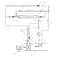
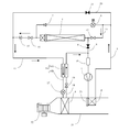
- FIG.1 and FIG.2 shows the outline
- the refrigerant circuit to which the vehicle interior heat exchanger according to the present invention is applied is not limited to this.
- the air conditioner includes a compressor 1, a first vehicle interior heat exchanger 2 disposed on the downstream side of the air passage 51 in the vehicle interior, a vehicle exterior heat exchanger 3 disposed outside the vehicle interior, and an air passage in the vehicle interior.
- 51 includes a second vehicle interior heat exchanger 4 disposed on the upstream side of 51.
- a fan 52 is disposed at the upstream end of the air passage 51, and a damper 53 that can freely open and close the air vent is attached to the air vent of the first vehicle interior heat exchanger 2.
- a first expansion valve 6 and a first check valve 7 are provided in the middle of the first refrigerant pipe 5 from the refrigerant discharge port of the compressor 1 through the first vehicle interior heat exchanger 2 to the vehicle exterior heat exchanger 3.
- a first on-off valve 9 and an accumulator 10 are interposed in the middle of the second refrigerant pipe 8 from the vehicle exterior heat exchanger 3 to the refrigerant inlet of the compressor 1.
- a third refrigerant pipe 11 is connected from the downstream side of the first expansion valve 6 of the first refrigerant pipe 5 to connect the exterior heat exchanger 3 and the first on-off valve 9, and the third refrigerant pipe 11 is connected to the third refrigerant pipe 11.
- the second on-off valve 12 is interposed.
- the first expansion valve 6 is substantially closed because the passage resistance is larger than that of the second on-off valve 12, but may be forcibly closed. Therefore, the first expansion valve 6 and the second on-off valve 12 are selectively opened.
- a fifth refrigerant pipe 18 extending from the second vehicle interior heat exchanger 4 to the first on-off valve 9 and the accumulator 10 is connected.
- the fifth refrigerant pipe 18 includes a fourth on-off valve 19 and an internal heat exchanger. Sixteen low temperature parts are interposed.
- the internal heat exchanger 16 exchanges heat between the high-temperature refrigerant that flows through the high-temperature part 16A and the low-temperature refrigerant that flows through the low-temperature part 16B.
- a sixth refrigerant pipe 20 is arranged from the upstream side of the first expansion valve 6 of the first refrigerant pipe 5 to the downstream side of the check valve 15 of the fourth refrigerant pipe 13, and the sixth refrigerant pipe 20 includes: A fifth on-off valve 21 is interposed.
- the high-temperature / high-pressure gas refrigerant pressurized by the compressor 1 flows into the first vehicle interior heat exchanger 2 and condenses by exchanging heat (dissipating heat) with the air blown from the fan 52. ⁇ Liquefied.
- the air is heated by this heat exchange.
- the heated air is blown into the passenger compartment to heat the passenger compartment.
- the liquid refrigerant is depressurized through the first expansion valve 6 to be in a gas-liquid mixed state, and flows into the vehicle exterior heat exchanger 3 through the first check valve 7.
- the refrigerant exchanges heat with the outside air (heat absorption) and is vaporized (gasified), and then returned to the inlet of the compressor 1 through the first on-off valve 9 and pressurized. Is repeated.
- the second on-off valve 12, the third on-off valve 14, and the fourth on-off valve 19 are opened, and the damper 53, the first expansion valve 6, the first on-off valve 9, and the fifth on-off valve 21 are closed. Is done.
- the refrigerant pressurized by the compressor 1 flows through the first vehicle interior heat exchanger 2, but the damper 53 is closed and air flow to the first vehicle interior heat exchanger 2 is blocked. Therefore, heat exchange (cooling) with the blown air is hardly performed, and the refrigerant flows out in a high-temperature / high-pressure gas state and flows into the vehicle exterior heat exchanger 3 via the second on-off valve 12.
- the exterior heat exchanger 3 functions as a condenser, and heat exchange (heat radiation) with the outside air condenses and liquefies the gas refrigerant.
- the liquid refrigerant passes through the third opening / closing valve 14, the check valve 15, and the low temperature portion 16A of the internal heat exchanger 16, reaches the second expansion valve 17, and is decompressed by the second expansion valve 17 to be in a gas-liquid mixed state.
- the refrigerant is gasified by exchanging heat (absorbing heat) with the air blown from the fan 52. The air cooled by this heat exchange is blown into the vehicle interior to cool the vehicle interior.
- the air that has been cooled and condensed by the second vehicle interior heat exchanger 4 to reduce moisture is transferred to the downstream first vehicle interior. It can be reheated by the heat exchanger 2 and blown air having a low relative humidity into the passenger compartment.
- the refrigerant that is supplied to the second vehicle interior heat exchanger 4 is opened by opening the fifth on-off valve 21 interposed in the sixth refrigerant pipe 20. The flow rate may be increased.
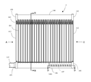
- FIG. 3 is a front view of the second vehicle interior heat exchanger 2 as viewed from the downstream side in the air blowing direction
- FIG. 4 is a view taken in the direction of arrow A in FIG. 3
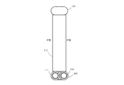
- FIG. 6 is a side view of FIG.
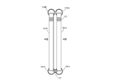
- a pair of tube groups 103A and 103B are formed in which a plurality of refrigerant flow tubes 101 having a flat passage section and extending in the vertical direction are arranged in parallel via corrugated fins 102 (only the upper part is shown in the figure).
- the tube groups 103A and 103B are opposed to each other, and are arranged in two rows on the upstream side and the downstream side with an interval in the blowing direction of the blowing path 51.
- Each refrigerant circulation tube 101 and corrugated fin 102 are fixed by brazing or the like.
- a pair of cylindrical headers extending in the horizontal direction is provided on each of the upper and lower sides of the two rows of tube groups 103A and 103B.
- the pair of headers 104A, 104B disposed on the upper side of the two rows of tube groups 103A, 103B each have a plurality of holes for inserting one end (upper end) of the refrigerant flow tube 101 of each tube group.
- the upper end portions of the tube groups 103A and 103B are inserted into the corresponding holes of the headers 104A and 104B and fixed by brazing.
- the upper headers 104A and 104B are fixed by brazing, with the open ends on both sides closed by the lid member 105.
- the pair of headers 106A and 106B disposed on the lower side of the refrigerant flow tube 101 has a plurality of holes for inserting the lower ends of the refrigerant flow tubes 11 of the tube groups 103A and 103B, respectively, like the headers 104A and 104B.
- the lower ends of the tube groups 103A and 103B are inserted into a plurality of corresponding holes in the headers 106A and 106B and fixed by brazing.
- One open end (the right side in the figure) of the lower headers 106A and 106B is closed by a lid member 108 and fixed by brazing.
- a pipe joint 109 having an opening at the center is fixed by brazing to the other open end (the left side in the figure) of the headers 106A and 106B, and a refrigerant inflow pipe 110 is connected to the pipe joint 109 on the header 106A side.
- the refrigerant outflow pipe 111 is connected and fixed to the pipe joint 109 on the header 106B side by brazing.
- the internal space of the headers 106A and 106B is partitioned into two by a disk-shaped partition member 106b in the intermediate portion in the axial direction.
- the partition member 106b is fixed by brazing to the inner walls of the pair of headers 106A and 106B.
- the two partition members 106b are provided at positions away from the refrigerant inflow pipe 110 and the refrigerant outflow pipe 111 from the central position of the internal space. Further, a plurality (nine in the figure) are provided on the opposing inner walls on the side (right side in the figure) on the side separated from the refrigerant inflow pipe 110 and the refrigerant outflow pipe 111 separated by the partition members 106b of the headers 106A and 106B. Boss through-hole 106c is formed.
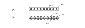
- connecting members 107 are formed on both sides of the flat portion of the plate-like member so that bosses 107a having communication holes 107b on the inside are projected, as shown in FIG.
- the boss portion 107a of the connection member 107 is passed through the boss through holes 106c of the headers 106A and 106B, and is fixed by brazing.
- the boss portion 107a of the connecting plate 107 is formed, for example, by forming a pair of burring so as to protrude from one surface of one plate material, and stacking them in the opposite direction and fixing them by brazing or the like. be able to. Or after making it protrude on the one side surface of one board
- the reinforcing plates 112 are brazed and fixed to both ends in the stacking direction of the tube groups 103A, 103B, 106A, 106B.
- the 1st vehicle interior heat exchanger 2 is arrange
- the heat exchanger (second heat exchanger) on the downstream side in the refrigerant flow direction is connected and connected through a communication hole.
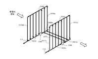
- the refrigerant flow in the first vehicle interior heat exchanger 2 having such a configuration is as shown by the arrow in FIG.
- the refrigerant flows into the header 106A on the lower side of the first heat exchanger from the refrigerant inflow pipe 110, and a plurality (14 in FIG. 3) of refrigerant circulation tubes facing the first header space 106Au on the front side of the partition plate 106b.
- 101 first tube group 103Au
- the refrigerant flows into the third header inner space 106Bu through the lower end openings of a plurality (ten in FIG. 3) of refrigerant circulation tubes 101 (third tube group 103Bu), and flows upward through the third tube group 103Bu.
- FIG. 1 When the vehicle interior heat exchanger 2 functions as a condenser during heating, the refrigerant contacts the outer surfaces of the tubes 101 while passing through the refrigerant flow tubes 101 of the two tube groups 103A and 103B as described above. In addition, heat is exchanged with the circulated air that circulates and is dissipated, and heat is exchanged with the corrugated fins 102 that are also cooled by the blast air that is in contact with the outer surface. Is done.
- the heat exchanger defined in four heat exchange regions constituted by the first to fourth tube groups (first to fourth passes) while reversing the refrigerant flow direction. Is referred to as a four-pass heat exchanger.
- the refrigerant flows from the refrigerant inflow pipe through all the tube groups of the first heat exchanger to the second heat exchanger at the same time, and flows through all the tube groups of the second heat exchanger at the same time and flows out from the refrigerant outflow pipe.
- the heat exchanger having two heat exchange regions is referred to as a two-pass heat exchanger.
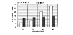
- FIG. 9 shows a comparison of the temperature difference between the four-pass indoor heat exchanger functioning as a condenser during heating (difference between the maximum and minimum outlet temperatures in the total heat exchange region) with that of the two-pass indoor heat exchanger. Show. However, the four-pass indoor heat exchanger was confirmed to have the same size (cross-sectional area in the direction perpendicular to the blowing direction) of the four heat exchange regions.
- the supercooling region where the liquid refrigerant condensed in the second heat exchanger on the downstream side is small is small, but the supercooling temperature is 40 ° C.
- the supercooling region is expanded.
- the heat exchange efficiency with the blown air is high, and compared with other regions, it is given to the blowout temperature of the blown air that has passed through the supercooling region and has been heat-exchanged. A large impact. As a result, the blowing temperature difference increases as the supercooling region increases.
- the 4-pass indoor heat exchanger When operating at a supercooling temperature of 30 ° C and 35 ° C where the supercooling region is small, the 4-pass indoor heat exchanger has a larger discharge temperature difference than the 2-pass indoor heat exchanger, but 15 ° C The following good levels are maintained.
- the refrigerant flow path is long and the temperature change of the refrigerant becomes gentle, so the expansion of the supercooling region can be suppressed and a little of the heat exchange region of the second heat exchanger is slightly reduced. It is suppressed to the extent of exceeding. As a result, an increase in the blowing temperature difference can be suppressed and maintained at a good level of 15 ° C. or less.
- the heat exchange area of the fourth path (fourth tube group) of the four-pass indoor heat exchanger is set larger than the heat exchange area of the third path (third tube group).
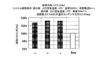
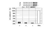
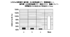
- 10 to 12 show the ratios of various state quantities to the two-pass indoor heat exchanger in which the sizes of the heat exchange areas of the first to fourth passes of the four-pass indoor heat exchanger are different, that is, heating.
- a COP ratio, a blowing temperature difference ratio, and a cooling COP ratio are shown.
- the heating conditions and cooling conditions are as shown in the figure, and the case of 45 ° C. supercooling operation is shown during heating.
- a is a heat exchange area of the third pass (second pass) set larger than the heat exchange area of the fourth pass (first pass). Specifically, the third pass (and the second pass). The number of tubes is 14 and the number of tubes in the fourth pass (and the first pass) is 10.
- b is the heat exchange area of the first to fourth passes set equal, and specifically, the number of tubes in each pass is twelve.
- the number of tubes in the fourth pass (and the first pass) is 14, and the number of tubes in the third pass (and the second pass) is 10.
- the four-pass indoor heat exchanger has obtained good results that exceed the two-pass indoor heat exchanger by 5% or more for both a, b, and c.
- the 4-pass indoor heat exchanger is significantly smaller than the 2-pass indoor heat exchanger (both b, c). Is the same as shown in FIG. 9), and in particular, in the case of c (the present embodiment), the blow-off temperature difference ratio can be further reduced.
- the larger the heat exchange area in the fourth pass the smaller the temperature difference between the blowout temperatures.
- the heat exchange area in the third pass becomes relatively small, the cooling operation of the system is performed.
- the passage resistance when the refrigerant is passed in the gas state increases, and the cooling COP decreases.
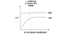
- FIG. 14 shows the relationship between the refrigerant passage area of the first heat exchanger (the smaller tube group total cross-sectional area of the first pass and the second pass) and COP, and is maintained substantially constant during heating. It has been shown that a good COP can be obtained when the area of the refrigerant passage is larger than the cross-sectional area of the refrigerant introduction pipe during cooling.
- the refrigerant passage area (total cross-sectional area of 10 tubes)
- the size is larger than the cross-sectional area.
- the cooling COP ratio c (this embodiment) is less than a and b, but 92.5% of the two-pass indoor heat exchanger can be secured. It is clear that the cooling performance can be maintained well.
- pass is not restricted to the example of the said embodiment, For example, it is good also as 50% (every 12 tubes), As in the embodiment, by matching the proportion of the heat exchange area between the fourth pass and the first pass (14 and 10 tubes), the first pass with the highest temperature and the fourth pass with the lowest temperature Therefore, it is possible to further reduce the variation in the blowing temperature.
- the common heat exchanger is changed in the left and right direction. It becomes possible to attach (the heat exchange area ratio of the first pass to the fourth pass does not change), and versatility is obtained and the cost can be reduced.
- the shape of the heat exchanger is normally set to be horizontally long, in the heat exchanger in which the refrigerant flow tube 101 is arranged in the vertical direction as in this embodiment, the refrigerant flow tube is placed horizontally as in Patent Document 1.
- the number of tubes per pass can be increased. Thereby, refrigerant
Landscapes
- Engineering & Computer Science (AREA)
- Physics & Mathematics (AREA)
- Thermal Sciences (AREA)
- Mechanical Engineering (AREA)
- General Engineering & Computer Science (AREA)
- Air-Conditioning For Vehicles (AREA)
- Heat-Exchange Devices With Radiators And Conduit Assemblies (AREA)
Abstract
Description
上下方向に延びる複数の冷媒流通チューブを互いに平行に配置したチューブ群の上下端部を水平方向に延びる上下のヘッダに連通接続した熱交換器を一対形成し、冷媒流通方向上流側の第1熱交換器を室内への空気送風方向の下流側、冷媒流通方向下流側の第2熱交換器を前記空気送風方向の上流側に並べて配置すると共に、前記第1熱交換器及び第2熱交換器の隣接するヘッダ同志を連通接続し、暖房時に35℃を超える過冷却運転が可能なコンデンサとして機能し、冷房時に冷媒をガス状態で通過させるカウンターフロー型の室内熱交換器であって、
前記第1熱交換器及び第2熱交換器の少なくとも一部のヘッダ内を水平方向複数の空間に仕切り、各熱交換器のチューブ群を、隣接するチューブ群相互間で冷媒流通方向を反転させた複数の熱交換領域に画成すると共に、前記第2熱交換器において、冷媒流通方向最下流側の熱交換領域を、上流側の熱交換領域より大きく設定し、
前記第1熱交換器において、前記各熱交換領域の冷媒通路面積を該第1熱交換器に接続された冷媒導入管の断面積より大きく設定したこと、
を特徴とする。
過冷却温度が35℃を超える高レベルの過冷却運転を行った場合、第2熱交換器において過冷却される低温領域が拡大するが、第1熱交換器及び第2熱交換器の熱交換領域をそれぞれ複数に画成することにより、送風空気との熱交換による温度変化が緩やかとなり、複数に画成しない場合に比較すると過冷却領域の拡大を抑制できる。
一方、冷房運転時は、特に冷媒流通方向上流側の第1熱交換器では高温・高圧のガス冷媒が流通するが、各熱交換領域におけるチューブ群の冷媒通路面積(チューブ群の総断面積)を冷媒導入管の断面積より大きくしたことにより、流通抵抗の増大を抑制してヒートポンプシステムの冷房性能を良好に維持することができる。
図1及び図2は、本発明に係る室内熱交換器(コンデンサ)を備えたヒートポンプ式の車両用空調装置における冷媒回路の概要を示す。なお、本発明に係る車室内熱交換器が適用される冷媒回路は、これに限らない。
コンプレッサ1の冷媒吐出口から第1車室内熱交換器2を経て車室外熱交換器3に至る第1冷媒配管5の途中には、第1膨張弁6及び第1逆止弁7が介装されている。車室外熱交換器3からコンプレッサ1の冷媒吸入口に至る第2冷媒配管8の途中には、第1開閉弁9及びアキュームレータ10が介装されている。
暖房時には、ダンパ53、第1膨張弁6及び第1開閉弁9が開とされ、第2開閉弁12、第3開閉弁14、第4開閉弁19及び第5開閉弁21が閉とされる。
図2に示すように、コンプレッサ1で加圧された冷媒は、第1車室内熱交換器2を流通するが、ダンパ53が閉とされて第1車室内熱交換器2への送風が遮断されているため、送風空気との熱交換(冷却)が殆ど行われず、冷媒は高温・高圧のガス状態のまま流出し、第2開閉弁12を介して車室外熱交換器3に流入する。
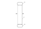
図3は、第2車室内熱交換器2を空気の送風方向下流側からみた正面図、図4は、図3のA矢視図、図5は、図3のB-B矢視断面図、図6は、図3のC矢視側面図である。
2列のチューブ群103A,103Bの上側に配設される一対のヘッダ104A,104Bは、それぞれ各チューブ群の冷媒流通チューブ101の一端部(上端部)を挿入するための複数の孔を有し、各チューブ群103A,103Bの上端部は、ヘッダ104A,104Bの対応する孔に挿入され、ろう付けして固定される。
冷媒流通チューブ101の下側に配設される一対のヘッダ106A,106Bは、ヘッダ104A,104Bと同様、それぞれ各チューブ群103A,103Bの冷媒流通チューブ11の下端部を挿入するための複数の孔を有し、各チューブ群103A,103Bの下端部は、ヘッダ106A,106Bの対応する複数の孔に挿入され、ろう付けして固定される。
ヘッダ106A,106Bの他方(図示左側)の開口端には、中央部を開口した管継手109がろう付けして固定され、ヘッダ106A側の管継手109には冷媒流入管110が接続してろう付け固定され、ヘッダ106B側の管継手109には冷媒流出管111が接続してろう付け固定される。
さらに、ヘッダ106A,106Bの仕切り部材106bで仕切られた、冷媒流入管110及び冷媒流出管111から離れた側(図示右側)の部分には、対向する内壁にそれぞれ複数(図では、9個)のボス貫通孔106cが形成される。
以上のように、第1車室内熱交換器2は、送風路の送風方向下流側に配置される冷媒流通方向上流側の熱交換器(第1熱交換器)と送風方向上流側に配置される冷媒流通方向下流側の熱交換器(第2熱交換器)とを、連通孔を介して連通接続して構成される。
冷媒は、冷媒流入管110から第1熱交換器の下側のヘッダ106A内に流入し、仕切り板106bより手前側の第1ヘッダ空間106Auに臨む複数(図3では14本)の冷媒流通チューブ101(第1チューブ群103Au)の下端開口から流入して、第1チューブ群103Auを上方に流動する。
次いで、第2ヘッダ空間106Ad内に臨む接続部材7のボス部107a内の連通孔107bを通って、隣接する第2熱交換器のヘッダ106Bの仕切り板106bより奥側の第3ヘッダ空間106Buに流入する。
暖房時に車室内熱交換器2がコンデンサとして機能する際は、冷媒は、上記のように2つのチューブ群103A,103Bの各冷媒流通チューブ101を通る間に、これら各チューブ101の外表面に接触しつつ流通する送風空気と熱交換して放熱されると共に、同じく外表面に接触する送風空気によって冷却されるコルゲートフィン102と熱交換して放熱されることにより、効率よく冷却されて凝縮・液化される。
図10~図12は、4パス型室内熱交換器の第1パス~第4パスの各熱交換領域の大きさが異なる組み合わせの2パス型室内熱交換器に対する各種状態量の比率、すなわち暖房COP比率、吹出し温度差比率、冷房COP比率を示す。暖房条件、冷房条件については、図に記載の通りであり、暖房時は45°Cの過冷却運転の場合を示す。
cは、上記本発明の実施形態に該当し、第4パスの熱交換領域(=第1パスの熱交換領域)を第4パスの熱交換領域(=第1パスの熱交換領域)より大きく設定したものであり、具体的には、第4パス(及び第1パス)のチューブ本数を14本、第3パス(及び第2パス)のチューブ本数を10本としたものである。
図11に示すように、吹出し温度差比率(小さいほど良好)については、4パス型室内熱交換器は、a,b,c共に、2パス型室内熱交換器より大幅に小さくなる(bについては、図9でも示したとおりである)が、特に、c(本実施形態)では吹出し温度差比率をより小さくすることができる。
Claims (4)
- 上下方向に延びる複数の冷媒流通チューブを互いに平行に配置したチューブ群の上下端部を水平方向に延びる上下のヘッダに連通接続した熱交換器を一対形成し、冷媒流通方向上流側の第1熱交換器を室内への空気送風方向の下流側、冷媒流通方向下流側の第2熱交換器を前記空気送風方向の上流側に並べて配置すると共に、前記第1熱交換器及び第2熱交換器の隣接するヘッダ同志を連通接続し、暖房時に35℃を超える過冷却運転が可能なコンデンサとして機能し、冷房時に冷媒をガス状態で通過させるカウンターフロー型の室内熱交換器であって、
前記第1熱交換器及び第2熱交換器の少なくとも一部のヘッダ内を水平方向複数の空間に仕切り、各熱交換器のチューブ群を、隣接するチューブ群相互間で冷媒流通方向を反転させた複数の熱交換領域に画成すると共に、前記第2熱交換器において、冷媒流通方向最下流側の熱交換領域を、上流側の熱交換領域より大きく設定し、
前記第1熱交換器において、前記各熱交換領域の冷媒通路面積を該第1熱交換器に接続された冷媒導入管の断面積より大きく設定したこと、
を特徴とする室内熱交換器。 - 前記第1熱交換器において、冷媒流通方向最上流側の熱交換領域を、下流側の熱交換領域より大きく設定したこと、
を特徴とする請求項1に記載の室内熱交換器。 - 前記第1熱交換器及び第2熱交換器のチューブ群をそれぞれ2個に画成し、前記第1熱交換器における冷媒流通方向上流側の熱交換領域と、前記第2熱交換器における冷媒流通方向下流側の熱交換領域の大きさを等しくし、前記第1熱交換器における冷媒流通方向下流側の熱交換領域と、前記第2熱交換器における冷媒流通方向上流側の熱交換領域の大きさを等しくしたことを特徴とする請求項2に記載の室内熱交換器。
- 車両用空調装置の車室への送風路に配設され、暖房時は、通気口を開とされ、冷房時は通気口を閉とされることと特徴とする請求項1~請求項3のいずれか1つに記載の室内熱交換器。
Priority Applications (3)
| Application Number | Priority Date | Filing Date | Title |
|---|---|---|---|
| US14/893,610 US20160109192A1 (en) | 2013-05-24 | 2014-05-22 | Interior heat exchanger |
| CN201480029621.0A CN105229406B (zh) | 2013-05-24 | 2014-05-22 | 室内热交换器 |
| DE112014002553.4T DE112014002553T5 (de) | 2013-05-24 | 2014-05-22 | Innenwärmetauscher |
Applications Claiming Priority (2)
| Application Number | Priority Date | Filing Date | Title |
|---|---|---|---|
| JP2013-110297 | 2013-05-24 | ||
| JP2013110297A JP6026956B2 (ja) | 2013-05-24 | 2013-05-24 | 室内熱交換器 |
Publications (1)
| Publication Number | Publication Date |
|---|---|
| WO2014189111A1 true WO2014189111A1 (ja) | 2014-11-27 |
Family
ID=51933662
Family Applications (1)
| Application Number | Title | Priority Date | Filing Date |
|---|---|---|---|
| PCT/JP2014/063603 Ceased WO2014189111A1 (ja) | 2013-05-24 | 2014-05-22 | 室内熱交換器 |
Country Status (5)
| Country | Link |
|---|---|
| US (1) | US20160109192A1 (ja) |
| JP (1) | JP6026956B2 (ja) |
| CN (1) | CN105229406B (ja) |
| DE (1) | DE112014002553T5 (ja) |
| WO (1) | WO2014189111A1 (ja) |
Families Citing this family (5)
| Publication number | Priority date | Publication date | Assignee | Title |
|---|---|---|---|---|
| CN110234523B (zh) * | 2017-02-10 | 2022-10-18 | 日本碍子株式会社 | 冷风暖风产生系统 |
| JP6678620B2 (ja) * | 2017-04-12 | 2020-04-08 | 日立ジョンソンコントロールズ空調株式会社 | 室外機および冷凍サイクル装置 |
| JP6963526B2 (ja) * | 2018-03-23 | 2021-11-10 | サンデン・オートモーティブクライメイトシステム株式会社 | 熱交換器 |
| EP3901536B1 (en) * | 2018-12-19 | 2023-12-06 | Mitsubishi Electric Corporation | Heat exchanger and refrigeration cycle device |
| DE102021208038A1 (de) * | 2021-07-26 | 2023-01-26 | Mahle International Gmbh | Verdampfer |
Citations (7)
| Publication number | Priority date | Publication date | Assignee | Title |
|---|---|---|---|---|
| JPH01131891A (ja) * | 1987-11-17 | 1989-05-24 | Nippon Denso Co Ltd | 熱交換器 |
| JP2001304775A (ja) * | 2000-04-26 | 2001-10-31 | Mitsubishi Heavy Ind Ltd | 車両用空気調和装置 |
| JP2002090076A (ja) * | 2000-09-14 | 2002-03-27 | Calsonic Kansei Corp | エバポレータ |
| JP2002147891A (ja) * | 2000-11-15 | 2002-05-22 | Science Kk | 冷凍サイクルからなる給湯装置 |
| JP2009121728A (ja) * | 2007-11-13 | 2009-06-04 | Denso Corp | 多面体構造の熱交換器及びその製造方法 |
| US20110100614A1 (en) * | 2007-11-09 | 2011-05-05 | Halla Climate Control Corp. | Heat exchanger |
| WO2012118198A1 (ja) * | 2011-03-03 | 2012-09-07 | サンデン株式会社 | 車両用空気調和装置 |
Family Cites Families (12)
| Publication number | Priority date | Publication date | Assignee | Title |
|---|---|---|---|---|
| US5685162A (en) * | 1991-04-26 | 1997-11-11 | Nippondenso Co., Ltd. | Automotive air conditioner having condenser and evaporator provided within air duct |
| EP0851188B8 (en) * | 1996-12-25 | 2006-01-11 | Calsonic Kansei Corporation | Condenser assembly structure |
| US20020007646A1 (en) * | 2000-06-20 | 2002-01-24 | Showa Denko K.K. | Condenser |
| US6745827B2 (en) * | 2001-09-29 | 2004-06-08 | Halla Climate Control Corporation | Heat exchanger |
| KR100638490B1 (ko) * | 2002-05-29 | 2006-10-25 | 한라공조주식회사 | 열교환기 |
| EP1582834B1 (en) * | 2004-04-02 | 2010-10-06 | Calsonic Kansei Corporation | Evaporator |
| DE102004018317A1 (de) * | 2004-04-13 | 2005-11-03 | Behr Gmbh & Co. Kg | Wärmeübertrager für Kraftfahrzeuge |
| CN101038115A (zh) * | 2006-03-19 | 2007-09-19 | 陈苏红 | 汽车空调装置双层薄型多段式平行流蒸发器 |
| US20110139421A1 (en) * | 2009-12-15 | 2011-06-16 | Delphi Technologies, Inc. | Flow distributor for a heat exchanger assembly |
| JP2011140291A (ja) * | 2010-01-11 | 2011-07-21 | Denso Corp | 車両用空調装置 |
| JP5200045B2 (ja) * | 2010-03-15 | 2013-05-15 | 本田技研工業株式会社 | 熱交換器 |
| FR2965606B1 (fr) * | 2010-09-30 | 2015-04-17 | Valeo Systemes Thermiques | Echangeur de chaleur pour vehicule automobile |
-
2013
- 2013-05-24 JP JP2013110297A patent/JP6026956B2/ja active Active
-
2014
- 2014-05-22 DE DE112014002553.4T patent/DE112014002553T5/de active Pending
- 2014-05-22 CN CN201480029621.0A patent/CN105229406B/zh active Active
- 2014-05-22 WO PCT/JP2014/063603 patent/WO2014189111A1/ja not_active Ceased
- 2014-05-22 US US14/893,610 patent/US20160109192A1/en not_active Abandoned
Patent Citations (7)
| Publication number | Priority date | Publication date | Assignee | Title |
|---|---|---|---|---|
| JPH01131891A (ja) * | 1987-11-17 | 1989-05-24 | Nippon Denso Co Ltd | 熱交換器 |
| JP2001304775A (ja) * | 2000-04-26 | 2001-10-31 | Mitsubishi Heavy Ind Ltd | 車両用空気調和装置 |
| JP2002090076A (ja) * | 2000-09-14 | 2002-03-27 | Calsonic Kansei Corp | エバポレータ |
| JP2002147891A (ja) * | 2000-11-15 | 2002-05-22 | Science Kk | 冷凍サイクルからなる給湯装置 |
| US20110100614A1 (en) * | 2007-11-09 | 2011-05-05 | Halla Climate Control Corp. | Heat exchanger |
| JP2009121728A (ja) * | 2007-11-13 | 2009-06-04 | Denso Corp | 多面体構造の熱交換器及びその製造方法 |
| WO2012118198A1 (ja) * | 2011-03-03 | 2012-09-07 | サンデン株式会社 | 車両用空気調和装置 |
Also Published As
| Publication number | Publication date |
|---|---|
| JP6026956B2 (ja) | 2016-11-16 |
| CN105229406B (zh) | 2017-12-08 |
| CN105229406A (zh) | 2016-01-06 |
| US20160109192A1 (en) | 2016-04-21 |
| JP2014228242A (ja) | 2014-12-08 |
| DE112014002553T5 (de) | 2016-02-25 |
Similar Documents
| Publication | Publication Date | Title |
|---|---|---|
| JP6097065B2 (ja) | ヒートポンプシステム | |
| JP5875918B2 (ja) | 車室内熱交換器及び車室内熱交換器のヘッダ間接続部材 | |
| JP2017144951A (ja) | 車両用空調装置 | |
| WO2013151008A1 (ja) | 熱交換器及びそれを用いたヒートポンプシステム | |
| JP6026956B2 (ja) | 室内熱交換器 | |
| JP2013002774A (ja) | パラレルフロー型熱交換器及びそれを搭載した空気調和機 | |
| JP2018012365A (ja) | 車両用空調装置 | |
| KR102170459B1 (ko) | 차량용 에어컨시스템 | |
| TWI671494B (zh) | 除濕裝置 | |
| WO2020129496A1 (ja) | 凝縮器、車両用空気調和装置 | |
| JP6537928B2 (ja) | 熱交換器及びヒートポンプシステム | |
| JP7414845B2 (ja) | 冷凍サイクル装置 | |
| KR102609386B1 (ko) | 열교환기 및 이를 포함하는 차량용 공조장치 | |
| WO2021002288A1 (ja) | 空気調和ユニット、熱交換器、および空気調和機 | |
| CN111512099B (zh) | 热交换器及制冷循环装置 | |
| JP7137092B2 (ja) | 熱交換器 | |
| KR102161475B1 (ko) | 차량용 에어컨 시스템 | |
| KR102692196B1 (ko) | 차량용 공조시스템 | |
| KR20150098141A (ko) | 열교환기 및 이를 갖는 공기조화기 | |
| JP7213628B2 (ja) | 熱交換器、車両用空気調和装置 | |
| JP6974062B2 (ja) | 熱交換器 | |
| KR100556231B1 (ko) | 에어컨용 증발기 | |
| KR100986467B1 (ko) | 버스용 천정형 에어컨 장치 | |
| WO2022264375A1 (ja) | 除湿装置 | |
| WO2020003968A1 (ja) | 熱交換器、車両用空気調和装置 |
Legal Events
| Date | Code | Title | Description |
|---|---|---|---|
| WWE | Wipo information: entry into national phase |
Ref document number: 201480029621.0 Country of ref document: CN |
|
| 121 | Ep: the epo has been informed by wipo that ep was designated in this application |
Ref document number: 14800709 Country of ref document: EP Kind code of ref document: A1 |
|
| WWE | Wipo information: entry into national phase |
Ref document number: 14893610 Country of ref document: US Ref document number: 112014002553 Country of ref document: DE |
|
| 122 | Ep: pct application non-entry in european phase |
Ref document number: 14800709 Country of ref document: EP Kind code of ref document: A1 |