WO2014188598A1 - 内燃機関の燃料噴射弁 - Google Patents
内燃機関の燃料噴射弁 Download PDFInfo
- Publication number
- WO2014188598A1 WO2014188598A1 PCT/JP2013/064523 JP2013064523W WO2014188598A1 WO 2014188598 A1 WO2014188598 A1 WO 2014188598A1 JP 2013064523 W JP2013064523 W JP 2013064523W WO 2014188598 A1 WO2014188598 A1 WO 2014188598A1
- Authority
- WO
- WIPO (PCT)
- Prior art keywords
- injection
- spray
- valve
- fuel
- injection control
- Prior art date
- Legal status (The legal status is an assumption and is not a legal conclusion. Google has not performed a legal analysis and makes no representation as to the accuracy of the status listed.)
- Ceased
Links
Images






Classifications
-
- F—MECHANICAL ENGINEERING; LIGHTING; HEATING; WEAPONS; BLASTING
- F02—COMBUSTION ENGINES; HOT-GAS OR COMBUSTION-PRODUCT ENGINE PLANTS
- F02D—CONTROLLING COMBUSTION ENGINES
- F02D41/00—Electrical control of supply of combustible mixture or its constituents
- F02D41/02—Circuit arrangements for generating control signals
- F02D41/14—Introducing closed-loop corrections
- F02D41/1497—With detection of the mechanical response of the engine
- F02D41/1498—With detection of the mechanical response of the engine measuring engine roughness
-
- F—MECHANICAL ENGINEERING; LIGHTING; HEATING; WEAPONS; BLASTING
- F02—COMBUSTION ENGINES; HOT-GAS OR COMBUSTION-PRODUCT ENGINE PLANTS
- F02B—INTERNAL-COMBUSTION PISTON ENGINES; COMBUSTION ENGINES IN GENERAL
- F02B23/00—Other engines characterised by special shape or construction of combustion chambers to improve operation
- F02B23/08—Other engines characterised by special shape or construction of combustion chambers to improve operation with positive ignition
- F02B23/10—Other engines characterised by special shape or construction of combustion chambers to improve operation with positive ignition with separate admission of air and fuel into cylinder
- F02B23/104—Other engines characterised by special shape or construction of combustion chambers to improve operation with positive ignition with separate admission of air and fuel into cylinder the injector being placed on a side position of the cylinder
-
- F—MECHANICAL ENGINEERING; LIGHTING; HEATING; WEAPONS; BLASTING
- F02—COMBUSTION ENGINES; HOT-GAS OR COMBUSTION-PRODUCT ENGINE PLANTS
- F02D—CONTROLLING COMBUSTION ENGINES
- F02D41/00—Electrical control of supply of combustible mixture or its constituents
- F02D41/30—Controlling fuel injection
- F02D41/38—Controlling fuel injection of the high pressure type
- F02D41/40—Controlling fuel injection of the high pressure type with means for controlling injection timing or duration
- F02D41/402—Multiple injections
-
- F—MECHANICAL ENGINEERING; LIGHTING; HEATING; WEAPONS; BLASTING
- F02—COMBUSTION ENGINES; HOT-GAS OR COMBUSTION-PRODUCT ENGINE PLANTS
- F02M—SUPPLYING COMBUSTION ENGINES IN GENERAL WITH COMBUSTIBLE MIXTURES OR CONSTITUENTS THEREOF
- F02M61/00—Fuel-injectors not provided for in groups F02M39/00 - F02M57/00 or F02M67/00
- F02M61/16—Details not provided for in, or of interest apart from, the apparatus of groups F02M61/02 - F02M61/14
- F02M61/18—Injection nozzles, e.g. having valve seats; Details of valve member seated ends, not otherwise provided for
- F02M61/1806—Injection nozzles, e.g. having valve seats; Details of valve member seated ends, not otherwise provided for characterised by the arrangement of discharge orifices, e.g. orientation or size
- F02M61/184—Discharge orifices having non circular sections
-
- F—MECHANICAL ENGINEERING; LIGHTING; HEATING; WEAPONS; BLASTING
- F02—COMBUSTION ENGINES; HOT-GAS OR COMBUSTION-PRODUCT ENGINE PLANTS
- F02D—CONTROLLING COMBUSTION ENGINES
- F02D41/00—Electrical control of supply of combustible mixture or its constituents
- F02D41/30—Controlling fuel injection
- F02D41/38—Controlling fuel injection of the high pressure type
- F02D2041/389—Controlling fuel injection of the high pressure type for injecting directly into the cylinder
-
- F—MECHANICAL ENGINEERING; LIGHTING; HEATING; WEAPONS; BLASTING
- F02—COMBUSTION ENGINES; HOT-GAS OR COMBUSTION-PRODUCT ENGINE PLANTS
- F02D—CONTROLLING COMBUSTION ENGINES
- F02D2200/00—Input parameters for engine control
- F02D2200/02—Input parameters for engine control the parameters being related to the engine
- F02D2200/021—Engine temperature
-
- F—MECHANICAL ENGINEERING; LIGHTING; HEATING; WEAPONS; BLASTING
- F02—COMBUSTION ENGINES; HOT-GAS OR COMBUSTION-PRODUCT ENGINE PLANTS
- F02D—CONTROLLING COMBUSTION ENGINES
- F02D2200/00—Input parameters for engine control
- F02D2200/02—Input parameters for engine control the parameters being related to the engine
- F02D2200/06—Fuel or fuel supply system parameters
- F02D2200/063—Lift of the valve needle
-
- F—MECHANICAL ENGINEERING; LIGHTING; HEATING; WEAPONS; BLASTING
- F02—COMBUSTION ENGINES; HOT-GAS OR COMBUSTION-PRODUCT ENGINE PLANTS
- F02D—CONTROLLING COMBUSTION ENGINES
- F02D2200/00—Input parameters for engine control
- F02D2200/02—Input parameters for engine control the parameters being related to the engine
- F02D2200/10—Parameters related to the engine output, e.g. engine torque or engine speed
- F02D2200/101—Engine speed
-
- F—MECHANICAL ENGINEERING; LIGHTING; HEATING; WEAPONS; BLASTING
- F02—COMBUSTION ENGINES; HOT-GAS OR COMBUSTION-PRODUCT ENGINE PLANTS
- F02D—CONTROLLING COMBUSTION ENGINES
- F02D2200/00—Input parameters for engine control
- F02D2200/02—Input parameters for engine control the parameters being related to the engine
- F02D2200/10—Parameters related to the engine output, e.g. engine torque or engine speed
- F02D2200/1015—Engines misfires
-
- F—MECHANICAL ENGINEERING; LIGHTING; HEATING; WEAPONS; BLASTING
- F02—COMBUSTION ENGINES; HOT-GAS OR COMBUSTION-PRODUCT ENGINE PLANTS
- F02D—CONTROLLING COMBUSTION ENGINES
- F02D35/00—Controlling engines, dependent on conditions exterior or interior to engines, not otherwise provided for
- F02D35/02—Controlling engines, dependent on conditions exterior or interior to engines, not otherwise provided for on interior conditions
- F02D35/023—Controlling engines, dependent on conditions exterior or interior to engines, not otherwise provided for on interior conditions by determining the cylinder pressure
-
- Y—GENERAL TAGGING OF NEW TECHNOLOGICAL DEVELOPMENTS; GENERAL TAGGING OF CROSS-SECTIONAL TECHNOLOGIES SPANNING OVER SEVERAL SECTIONS OF THE IPC; TECHNICAL SUBJECTS COVERED BY FORMER USPC CROSS-REFERENCE ART COLLECTIONS [XRACs] AND DIGESTS
- Y02—TECHNOLOGIES OR APPLICATIONS FOR MITIGATION OR ADAPTATION AGAINST CLIMATE CHANGE
- Y02T—CLIMATE CHANGE MITIGATION TECHNOLOGIES RELATED TO TRANSPORTATION
- Y02T10/00—Road transport of goods or passengers
- Y02T10/10—Internal combustion engine [ICE] based vehicles
- Y02T10/12—Improving ICE efficiencies
-
- Y—GENERAL TAGGING OF NEW TECHNOLOGICAL DEVELOPMENTS; GENERAL TAGGING OF CROSS-SECTIONAL TECHNOLOGIES SPANNING OVER SEVERAL SECTIONS OF THE IPC; TECHNICAL SUBJECTS COVERED BY FORMER USPC CROSS-REFERENCE ART COLLECTIONS [XRACs] AND DIGESTS
- Y02—TECHNOLOGIES OR APPLICATIONS FOR MITIGATION OR ADAPTATION AGAINST CLIMATE CHANGE
- Y02T—CLIMATE CHANGE MITIGATION TECHNOLOGIES RELATED TO TRANSPORTATION
- Y02T10/00—Road transport of goods or passengers
- Y02T10/10—Internal combustion engine [ICE] based vehicles
- Y02T10/40—Engine management systems
Definitions
- the present invention relates to a fuel injection valve for an internal combustion engine.
- Patent Document 1 describes a fuel injection valve for an internal combustion engine.
- the fuel injection valve described in Patent Document 1 includes a slit-shaped injection hole.
- an object of the present invention is to provide a fuel injection valve capable of changing the flow rate distribution in the spray.
- the present invention relates to a fuel injection valve for an internal combustion engine.
- the needle lift amount is variable.
- the fuel injection valve of the present invention includes an injection hole having a slit-like cross section obtained by bending a rectangle at the center in the longitudinal direction. According to this, the flow rate distribution in the spray changes by changing the needle lift amount. Therefore, by changing the needle lift amount according to the engine operation state and the combustion state, it is possible to select a spray with a more suitable flow rate distribution.
- the fuel injection valve according to the present invention is configured such that, for example, when the lift amount of the intake valve is the maximum lift amount, the central axis of the injection hole passes through the space between the intake valves and the end axis of the injection hole is the intake valve. It is attached to the part of the engine body on the side of the intake valve at the upper part of the cylinder so as to pass through the lower space. In this case, even if the injection direction is closer to the intake valve (that is, the injection angle is small), the attachment of the intake valve is suppressed. Therefore, the injection angle can be made smaller while suppressing the intake valve adhesion.
- the fuel jet is easily synchronized with the flow of intake air, atomization is promoted, and the combustion state is improved.
- the spray angle can be set to a larger angle while suppressing the intake valve adhesion.
- the injection hole may be formed so that the end region of the injection hole is closer to the needle seat portion than the central region of the injection hole. According to this, when the fuel injection is switched from the partial lift injection to the full lift injection, the ratio of the injection amount from the nozzle hole end region to the total injection amount becomes large (and therefore relatively occupies the total injection amount). On the other hand, when the fuel injection is switched from the full lift injection to the partial lift injection, the ratio of the injection amount from the injection hole central region to the total injection amount becomes large (the ratio of the injection amount from the injection hole central region becomes small). Therefore, the ratio of the injection amount from the nozzle hole end region to the total injection amount is relatively small). That is, the flow distribution in the spray can be changed by changing the needle lift amount. Therefore, the required flow rate distribution in the spray can be achieved by changing the needle lift amount.
- the injection hole may be formed so that a central region of the injection hole is closer to the needle seat portion than an end region of the injection hole. According to this, when the fuel injection is switched from the partial lift injection to the full lift injection, the ratio of the injection amount from the central region of the injection hole to the total injection amount becomes large (and therefore, the relative injection to the total injection amount). On the other hand, when the full lift injection is switched to the partial lift injection, the ratio of the injection amount from the injection hole end region to the total injection amount increases (therefore, the ratio of the injection amount from the hole end region becomes small). Relatively, the ratio of the injection amount from the central region of the nozzle hole to the total injection amount becomes small). That is, the flow distribution in the spray can be changed by changing the needle lift amount. Therefore, the required flow rate distribution in the spray can be achieved by changing the needle lift amount.
- another invention of the present application is a fuel injection valve including a nozzle hole having a slit-shaped cross section obtained by bending a rectangle at a center in a longitudinal direction thereof, wherein the needle lift amount is variable
- the present invention relates to a fuel injection control device for an internal combustion engine including a fuel injection valve in which the injection hole is formed so that an end region of the hole is closer to a needle seat portion than a central region of the injection hole.
- the fuel injection control device of the present invention switches the injection control from the full lift injection control to the partial lift injection control when the combustion state becomes worse than the predetermined combustion state during the full lift injection control.
- the flow rate of the spray end during full lift injection is the same as that of the spray end during partial lift injection. More than the flow rate. Therefore, it is conceivable that the bore wall surface adheres as a cause of the deterioration of the combustion state during the full lift injection control.
- the injection control is switched from the full lift injection control to the partial lift injection control, the flow rate at the spray end decreases. Therefore, since the bore wall surface adhesion is eliminated, the combustion state can be improved.
- the fuel injection control device of the present invention may switch the injection control from the partial lift injection control to the full lift injection control when the combustion state becomes worse than a predetermined combustion state during the partial lift injection control.
- the flow rate of the spray end during partial lift injection is the same as that of the spray end during full lift injection. Less than the flow rate. Therefore, as a cause of deterioration of the combustion state during partial lift injection control, it is conceivable that the fuel at the spray end is difficult to burn (that is, the fuel does not easily burn, that is, the combustion speed is slow).
- the injection control is switched from the partial lift injection control to the full lift injection control, the flow rate at the spray end increases. Thereby, since combustion of the fuel of a spray end part is improved, a combustion state can be improved.
- Still another invention of the present application is a fuel injection valve including a nozzle hole having a slit-shaped cross section obtained by bending a rectangle at its center in the longitudinal direction, the needle lift amount being variable
- the present invention relates to a fuel injection control device for an internal combustion engine provided with a fuel injection valve in which the injection hole is formed such that a central region of the injection hole is closer to a needle seat portion than an end region of the injection hole.
- the fuel injection control device according to the present invention when the combustion state is worse than the predetermined combustion state during the full lift injection control at the time of low rotation and high load, if the engine temperature is higher than the predetermined temperature, the injection control is changed from the full lift injection control. Switch to partial lift injection control.
- the flow rate of the spray end during full lift injection is the same as that of the spray end during partial lift injection. Less than the flow rate. Therefore, the difficulty of combustion of the fuel at the spray end can be considered as a cause of deterioration of the combustion state during the full lift injection control.
- the injection control is switched from the full lift injection control to the partial lift injection control, the flow rate at the spray end increases. Thereby, since combustion of the fuel of a spray end part is improved, a combustion state can be improved.
- the reason why the engine temperature is higher than the predetermined temperature as a condition for switching the injection control from the full lift injection control to the partial lift injection control is that the fuel amount at the spray end is changed by switching to the partial lift injection control. This is because there is a concern about deterioration of the combustion state due to the adhesion of the bore wall surface. That is, even if the switch to the partial lift injection control is performed and the bore wall surface adheres, if the engine temperature is high, the fuel adhering to the bore evaporates immediately, so that the combustion state is hardly deteriorated.
- the fuel injection control device of the present invention may switch the injection control from the partial lift injection control to the full lift injection control when the combustion state becomes worse than a predetermined combustion state during the partial lift injection control.
- the flow rate of the spray end during partial lift injection is the same as that of the spray end during full lift injection. More than the flow rate. Therefore, it is conceivable that the bore wall surface adheres as a cause of the deterioration of the combustion state during the partial lift injection control.
- the injection control is switched from the partial lift injection control to the full lift injection, the flow rate at the spray end decreases. Therefore, since the bore wall surface adhesion is eliminated, the combustion state can be improved.
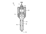
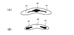
- FIG. 1 shows a fuel injection valve according to an embodiment of the present invention.
- FIG. 2A shows the change in the needle lift amount during full lift injection
- FIG. 2B shows the change in the needle lift amount during partial lift injection.
- FIG. 3 shows the vicinity of the injection hole of the fuel injection valve of the first embodiment.
- 4A shows the state of fuel spray during full lift injection
- FIG. 4B shows the state of fuel spray during partial lift injection.
- FIG. 5A is a diagram for explaining the spray angle at the time of full lift injection
- FIG. 5B is a diagram for explaining the spray angle at the time of partial lift injection.
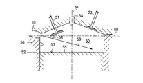
- FIG. 6 shows how the fuel injection valve of the first embodiment is attached to the main body of the internal combustion engine.
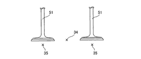
- FIG. 7 shows the relationship between the intake valve, the nozzle hole center axis, and the nozzle hole end axis.
- FIG. 8 shows the state of fuel spray injected from the fuel injection valve of the first embodiment.
- FIG. 9 shows the fuel injection control flow of the first embodiment.
- FIG. 10 shows the nozzle holes of the fuel injection valve of the second embodiment.
- FIG. 11A shows the state of fuel spray during full lift injection
- FIG. 11B shows the state of fuel spray during partial lift injection.
- FIG. 12 shows the fuel injection control flow of the second embodiment.
- FIG. 1 An embodiment of the fuel injector of the present invention is shown in FIG.
- 10 is a fuel injection valve (hereinafter “injection valve”)
- 11 is a nozzle
- 12 is a needle valve (valve element)
- 13 is a fuel injection hole (hereinafter “injection hole”)
- 14 is a fuel passage
- 15 is A solenoid
- 16 is a spring
- 17 is a fuel intake port
- 18 is an injection valve axis.
- the injection valve axis 18 is an axis extending in the longitudinal direction of the injection valve 10.
- the injection valve 10 is a so-called inner open type fuel injection valve.
- the injection valve 10 can selectively execute either one of the full lift injection and the partial lift injection.
- full lift injection is fuel injection that raises the needle valve 12 to the maximum lift amount (that is, maximum lift injection), and partial lift injection is shown in FIG. ),
- the needle lift amount can be controlled by controlling the energization time to the injection valve 10.
- FIG. 2A shows the needle lift amount of one full lift injection
- FIG. 2B shows the needle lift amount of three partial lift injections.
- FIG. 3A shows the tip of the injection valve 10 when the tip of the injection valve 10 is viewed from the outside of the injection valve 10 along the injection valve axis 18.
- 3B shows a cross section taken along line BB in FIG. 3A
- FIG. 3C shows a cross section taken along line CC in FIG. 3A.
- 11 is a nozzle
- 12 is a needle valve
- 13 is an injection hole
- 18 is an injection valve axis
- 20 is a sack
- 21 is a needle seat portion (hereinafter simply referred to as “seat portion”)
- 22 is a nozzle seat wall surface
- 23 is Needle seat wall surface
- 24 is an end surface of the injection hole
- 25 is a side surface of the injection hole
- 26 is a central region of the injection hole
- 27 is an end region of the injection hole
- 28 is an inlet
- 29 is an outlet
- 30 is a lateral width of the injection hole
- the hole longitudinal width, 32 is the bending angle
- 33 is the sack center
- 34 is the nozzle hole central axis
- 35 is the nozzle hole end axis.
- the sack center 33 is the center of the space constituting the sack 20 and is a point on the injection valve axis 18.
- the nozzle seat wall surface 22 is a wall surface on which the needle seat wall surface 23 is seated when the injection valve 10 is fully closed.
- the injection hole central axis 34 is an axis that penetrates the center of the injection hole 13 in the fuel flow direction (that is, the direction in which fuel flows in the injection hole).
- the nozzle hole end axis 35 is an axis passing through the end of the nozzle hole 13 in the fuel flow direction.
- the nozzle hole width 30 is a distance from the nozzle hole central axis 34 to the nozzle hole end face 24.
- the nozzle hole vertical width 31 is a distance between the nozzle hole side surfaces 25.
- the nozzle hole 13 has an inlet 28 and an outlet 29.
- the inlet 28 opens to the sack 20, and the fuel flows into the nozzle hole 13 from the inlet 28.
- the outlet 29 is open to the outside of the injection valve 10, and fuel is injected from the outlet 29.
- the inner region of the nozzle hole 13 is divided into a nozzle hole central region 26 and a nozzle hole end region 27.
- the nozzle hole central region 26 is a region extending from the inlet 28 to the outlet 29 along the nozzle hole central axis 34.
- the nozzle hole end region 27 is a region extending from the inlet 28 to the outlet 29 along each nozzle hole end axis 35 on both sides of the nozzle central region 26.
- the nozzle hole 13 when the nozzle hole 13 is viewed in its cross section, the nozzle hole 13 has a slit-like cross section obtained by bending a rectangle at the center in the longitudinal direction.
- the nozzle hole 13 when the nozzle hole 13 is viewed in its cross section, the nozzle hole 13 has a shape in which two parallelograms having the same shape are connected to each other at their short sides, and these short holes are connected to each other. Two parallelograms with respect to the sides have a shape that is line symmetric.
- the cross section of the nozzle hole is a section when the nozzle hole is cut along a plane perpendicular to the nozzle hole central axis 34.
- the nozzle hole lateral width 30 on one side of the nozzle hole central axis 34 is equal to the nozzle hole lateral width 30 on the other side of the nozzle hole central axis 34.
- the nozzle hole vertical width 31 is constant, and the nozzle hole vertical width 31 of the nozzle hole on one side of the nozzle hole central axis 34 is equal to the nozzle hole vertical width 31 on the other side of the nozzle hole central axis 34.
- the nozzle hole 13 when the nozzle hole 13 is viewed in a cross section BB, the nozzle hole 13 has a fan shape (strictly speaking, the center thereof) extending from the inlet 28 toward the outlet 29.
- a fan-shaped shape The cross section BB is a cross section when the nozzle hole is cut along two planes including the nozzle hole central axis 34 and each nozzle hole end axis 35. Therefore, the flow path area of the nozzle hole 13 gradually increases from the inlet 28 toward the outlet 29.
- the channel area of the outlet port 29 is larger than the channel area of the inlet port 28.
- the nozzle hole 13 when the nozzle hole 13 is viewed in its longitudinal section, the nozzle hole 13 has a rectangular shape.
- the vertical cross section of the injection hole is a cross section taken along a plane including the injection hole central axis 34 and the injection valve axis 18 or a plane including the injection hole end axis 35 and the injection valve axis 18. It is a cross section when cut.
- the nozzle hole 13 is formed at the tip of the nozzle 11 so that the nozzle hole central axis 34 intersects the sack center 33. Therefore, the nozzle hole end axis 35 does not intersect the sack center 33. Further, the nozzle hole 13 is formed such that the nozzle hole end region 27 is closer to the sheet portion 21 than the nozzle hole central region 26. That is, the nozzle hole is such that the distance between the end region 27 of the nozzle hole 13 and the closest sheet portion 21 is shorter than the distance between the central region 26 of the nozzle hole 13 and the closest sheet portion 21. 13 is formed. In other words, the nozzle hole 13 is formed such that the end region 27 of the nozzle hole 13 is close to the sheet portion 21 and the central region 26 of the nozzle hole 13 is far from the sheet portion 21.
- the injection hole central axis 34 coincides with the injection valve axis 18, but the injection hole central axis 34 may have an angle with respect to the injection valve axis 18.
- FIG. 4 shows fuel spray injected from the injection valve 10 of the first embodiment (hereinafter referred to as “spray”).
- FIG. 4 shows spraying when the tip of the injection valve 10 is viewed from the outside of the injection valve 10 along the injection valve axis 18.
- FIG. 4A shows spray during full lift injection
- FIG. 4B shows spray during partial lift injection.
- reference numeral 40 denotes spray sprayed from the nozzle hole central region 26 through the outlet 29 (hereinafter, “spray central part”), and 41 sprays from the nozzle hole end region 27 through the outlet 29. Spray (hereinafter “spray end”).
- the nozzle hole end region 27 is closer to the seat portion 21 than the nozzle hole central region 26.
- the flow rate (FIG. 4A) of the spray central portion 40 at the time of full lift injection is smaller than the flow rate of the spray central portion 40 at the time of partial lift injection (see FIG. 4B). That is, the ratio of the injection amount from the nozzle hole central region to the total injection amount at the time of full lift injection is smaller than the ratio of the injection amount from the nozzle hole central region to the total injection amount at the time of partial lift injection.
- the flow rate of the spray end 41 during full lift injection is larger than the flow rate of the spray end 41 during partial lift injection (see FIG. 4B). That is, the ratio of the injection amount from the nozzle hole end region to the total injection amount at the time of full lift injection is larger than the ratio of the injection amount from the nozzle hole end region to the total injection amount at the time of partial lift injection.
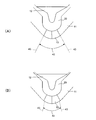
- the spray angle 42 during full lift injection (see FIG. 5A) is larger than the spray angle 42 during partial lift injection (see FIG. 5B).
- the penetration force at the time of full lift injection is larger than the penetration force at the time of partial lift injection.
- the spray angle 42 is an angle between the outer edges 43 of the spray, and the penetration force is a force that the spray travels in the cylinder.
- ⁇ Advantage 2 of Fuel Injection Valve of First Embodiment> The flow rate at the spray end during full lift injection is greater than the flow rate at the spray end during partial lift injection. For this reason, when full lift injection is selected as the injection mode, the flow rate of fuel flowing through the end region of the injection hole is large. Most of the deposits are deposited in the end region of the nozzle hole. Therefore, when there is a request to remove deposits accumulated in the nozzle holes or to suppress deposit accumulation in the nozzle holes, the deposits are deposited in the nozzle holes by selecting full lift injection as the injection mode. It is possible to remove the deposited deposit and to suppress the deposition of the deposit in the nozzle hole.
- the deposit is a substance generated by combustion in the cylinder, and is, for example, an unburned material such as fuel or lubricating oil.
- the combustion state can be grasped by, for example, the torque fluctuation amount, the in-cylinder pressure fluctuation amount, the engine speed fluctuation amount, the exhaust temperature, and the exhaust properties (for example, the unburned HC amount).
- the torque fluctuation amount is larger than a predetermined amount, or when the in-cylinder pressure fluctuation amount is larger than a predetermined amount, or when the engine rotational speed fluctuation amount is larger than a predetermined amount, or the exhaust
- the temperature is lower than the predetermined temperature, or when the exhaust property is worse than the predetermined property (for example, when the unburned HC amount is larger than the predetermined amount)
- the combustion state is worse than the predetermined combustion state.
- the torque fluctuation amount is the fluctuation amount of the engine output torque
- the fluctuation amount of the in-cylinder pressure is the fluctuation amount of the in-cylinder pressure (or the maximum value of the in-cylinder pressure) at the specific crank angle.
- the combustion state can be grasped by misfire, for example. That is, when the internal combustion engine has means for detecting misfire in the cylinder (for example, misfire sensor), when misfire occurs, or when the number of misfires within a predetermined time is greater than the predetermined number It can be determined that the combustion state is worse than the predetermined combustion state.
- misfire for example. That is, when the internal combustion engine has means for detecting misfire in the cylinder (for example, misfire sensor), when misfire occurs, or when the number of misfires within a predetermined time is greater than the predetermined number It can be determined that the combustion state is worse than the predetermined combustion state.
- the spray angle at the time of full lift injection is larger than the spray angle at the time of partial lift injection
- the penetration force at the time of full lift injection is larger than the penetration force at the time of partial lift injection. Therefore, according to the injection valve of the first embodiment, the spray having a more suitable characteristic in consideration of the spray angle and / or penetration force in addition to the flow rate distribution in the spray according to the engine operating state and the combustion state. Can be selected.
- the injection valve 10 is attached to a portion of the engine main body 52 on the side of the intake valve 51 in the upper part of the cylinder 50.
- the intake valve 51 is in the full lift state (that is, when the lift amount of the intake valve is the maximum lift amount, that is, the intake valve 51 is in the fully open state).
- the injection valve is a part of the engine body on the side of the intake valve on the upper side in the cylinder so that the central axis of the injection hole passes through the space between the intake valves and the axis of the injection hole end passes through the space below the intake valve. Attached to.
- the fuel injected from the central region of the injection hole through the outlet is usually the space between the intake valves 51. And the fuel injected from the nozzle hole end region through the outlet passes through the space below the intake valve 51.
- the bending angle of the injection hole 13 of the first embodiment is such that when the intake valve 51 is in the full lift state, the fuel injected from the central area of the injection hole through the outlet passes through the space between the intake valves 51.
- the angle is set such that the fuel injected from the nozzle hole end region through the outlet passes through the space below the intake valve 51.
- the bending angle of the nozzle hole 13 is set to an angle at which the attachment of the intake valve can be avoided.
- 53 is an exhaust valve
- 54 is a spark plug
- 55 is a piston
- 56 is a bore wall surface
- 57 is a piston top surface
- 58 is an in-cylinder pressure sensor
- 90 Is an electronic control unit (ECU).
- ECU electronice control unit
- the injection valve of the first embodiment since the spray central portion passes through the space between the intake valves and the spray end passes through the space below the intake valve, the intake air can be obtained without reducing the spray angle. No valve sticking occurs. That is, even if a large spray angle is set, the intake valve does not adhere. Therefore, according to the injection valve of the first embodiment, even if the injection valve is attached to the engine body so as to inject fuel into the cylinder in the direction of the intake valve from the side of the intake valve at the upper part of the cylinder, The spray angle can be set to a large angle while being suppressed.
- the injection angle is set to a small angle while suppressing the attachment of the intake valve. Can do.
- the injection hole has a slit shape that is not bent and the injection angle is small, when fuel is injected from the injection valve into the cylinder in the intake valve direction from the side of the intake valve at the upper part of the cylinder, the fuel is It will stick to the valve. Therefore, in order to avoid adhesion of the intake valve, it is necessary to increase the injection angle (that is, attach the injection valve to the engine body so that the injection direction is directed downward). However, it is not preferable to increase the injection angle from the viewpoints of suppressing the piston top surface adhesion (and hence smoke generation) and ensuring the spray homogeneity (and hence suppressing smoke generation).
- the injection valve of the first embodiment since the spray central portion passes through the space between the intake valves and the spray end passes through the space below the intake valve, the intake air can be obtained without increasing the injection angle. No valve sticking occurs. That is, even if a small injection angle is set, the intake valve does not adhere. Therefore, according to the injection valve of the first embodiment, even if the injection valve is attached to the engine body so as to inject fuel into the cylinder in the direction of the intake valve from the side of the intake valve at the upper part of the cylinder, The injection angle can be set to a small angle while suppressing. Thus, by setting the injection angle to a small angle, it is possible to suppress the adhesion of the piston top surface and to ensure the spray homogeneity.
- the injection angle is an angle in the injection direction with respect to a plane 60 that is perpendicular to the cylinder center axis 61 and passes through the nozzle hole 13, as indicated by reference numeral 58 in FIG.
- the downward direction is the piston top surface side along the cylinder center axis 61 in the cylinder 50
- the PM generation is the generation of particulate matter (fine particles) in the cylinder 50
- the smoke generation is the cylinder 50. Is the occurrence of smoke.
- the flow rate at the spray central portion at the time of full lift injection is the flow rate at the spray central portion at the time of partial lift injection (see FIG. 4B). Less). Further, the flow rate at the spray end during full lift injection (see FIG. 4A) is larger than the flow rate at the spray end during partial lift injection (FIG. 4B). Therefore, in the first embodiment, in view of the relationship between the needle lift amount and the flow rate distribution in the spray, the combustion state is changed from a predetermined combustion state during one of the full lift injection control and the partial lift injection control. If it also deteriorates, the injection control is switched to the other injection control.
- the injection control is switched from the full lift injection control to the partial lift injection control.
- the injection control is switched from the partial lift injection control to the full lift injection control.
- the full lift injection control is a control for executing full lift injection at a predetermined timing (specifically, a timing near the compression top dead center), and the partial lift injection control is a predetermined timing (specifically, In this case, the partial lift injection is executed at a timing near the compression top dead center.
- the total fuel injection amount before and after the switching is maintained at the same amount. That is, the total fuel injection amount after switching (that is, the total fuel injection amount during partial lift injection control) is maintained at the same amount as the total fuel injection amount before the switching (that is, total fuel injection amount during full lift injection control). It is preferable.
- the total fuel injection amount is the total amount of fuel injected by the fuel injection valve per engine cycle.
- a means for maintaining the same total fuel injection amount before and after switching for example, a means for increasing the number of injections per engine cycle in the partial lift injection control can be employed.
- the total fuel injection amount before and after the switching is preferably maintained at the same amount. That is, the total fuel injection amount after switching (that is, the total fuel injection amount during full lift injection control) is maintained at the same amount as the total fuel injection amount before the switching (that is, total fuel injection amount during partial lift injection control). It is preferable.
- the needle lift amount is selected according to the target flow rate distribution. Specifically, when the spray flow distribution with a large flow rate at the spray end is the target flow distribution, the full lift injection control is selected as the injection control, while the spray flow distribution with a small flow rate at the spray end is the target. In the case of the flow rate distribution, partial lift injection control is selected as the injection control.
- the injection control of the first embodiment when the combustion state becomes worse than the predetermined combustion state during the full lift injection control, the flow rate at the injection end and the penetration force at the spray end are reduced at the same time. Therefore, it can be said that the injection control is switched from the full lift injection control to the partial lift injection control.
- the partial lift injection control when the combustion state is a predetermined combustion state during the partial lift injection control, the partial lift injection control may be continued. However, when the combustion state is maintained in the predetermined combustion state even if the injection control is switched from the partial lift injection control to the full lift injection control when the combustion state is the predetermined combustion state during the partial lift injection control, the injection control is performed. May be switched from partial lift injection control to full lift injection control. According to this, while maintaining the combustion state in a predetermined combustion state, it is possible to remove deposits accumulated in the nozzle holes, and it is possible to obtain an advantage that deposit accumulation in the nozzle holes can be suppressed.
- FIG. 9 An example of the injection control flow of the first embodiment is shown in FIG.
- the flow in FIG. 9 is executed every time a predetermined time elapses.
- the target fuel injection amount Q is determined.
- CT> CTth a predetermined amount CTth
- CT> CTth a predetermined amount CTth
- the flag Ff is a flag that is set when the full lift injection control is being executed and is reset when the partial lift injection control is being executed.
- step 13 the partial lift amount (that is, the needle lift amount in one partial lift injection). ) Lp is determined.
- the number of injections Np is determined based on the target fuel injection amount Q determined at step 10 and the partial lift amount Lp determined at step 13. That is, the number of partial lift injections required to inject the fuel of the target fuel injection amount Q determined in step 10 is determined by the partial lift injection of the partial lift amount Lp determined in step 13.
- the injection control is switched from full lift injection control to partial lift injection control, and the flow ends. In this case, after the injection control is switched in step 15, the partial lift injection at the partial lift amount Lp determined in step 13 is executed for the number of injections Np determined in step 14 in each engine cycle of each cylinder. Is done.
- Second Embodiment A second embodiment will be described.
- the configuration and control of the second embodiment not described below are the same as the configuration and control of the first embodiment, respectively, or when considering the configuration or control of the second embodiment described below.
- the configuration and control are naturally derived from the configuration or control of the embodiment.
- FIG. 10A shows the tip of the injection valve when the tip of the injection valve is viewed from outside the injection valve along the axis of the injection valve.
- 10B shows a cross section taken along line BB in FIG. 10A
- FIG. 10C shows a cross section taken along line CC in FIG. 10A.
- shape of the nozzle hole 13 of 2nd Embodiment is the same as the shape of the nozzle hole 13 of 1st Embodiment.
- the nozzle hole 13 is formed at the tip of the nozzle 11 so that the nozzle hole end axis 35 intersects the sack center 33. Therefore, the nozzle hole central axis 34 does not intersect the sack center 33. Further, the nozzle hole 13 is formed so that the nozzle hole central region 26 is closer to the sheet portion 21 than the nozzle hole end region 27. That is, the injection hole is so formed that the distance between the central region 27 of the injection hole 13 and the closest sheet part 21 is shorter than the distance between the end region 27 of the injection hole 13 and the closest sheet part 21. 13 is formed. In other words, the nozzle hole 13 is formed such that the central region 26 of the nozzle hole 13 is close to the sheet portion 21 and the end region 27 of the nozzle hole 13 is far from the sheet portion 21.
- a plane including the two injection hole end axis 35 is on the injection valve axis 18, but this plane may have an angle with respect to the injection valve axis 18.
- FIG. 11 is a view similar to FIG. FIG. 11A shows the spray during full lift injection, and FIG. 11B shows the spray during partial lift injection.
- 40 is a spray center part, and 41 is a spray end part.
- the injection hole center region 26 is closer to the seat portion 21 than the injection hole end region 27.
- the flow rate (see FIG. 11A) of the spray central portion 40 at the time of full lift injection is larger than the flow rate of the spray central portion 40 at the time of partial lift injection (see FIG. 4B). That is, the ratio of the injection amount from the nozzle hole central region to the total injection amount at the time of full lift injection is larger than the ratio of the injection amount from the nozzle hole central region to the total injection amount at the time of partial lift injection.
- the flow rate of the spray end 41 during full lift injection is smaller than the flow rate of the spray end 41 during partial lift injection (see FIG. 4B). That is, the ratio of the injection amount from the nozzle hole end region to the total injection amount at the time of full lift injection is smaller than the ratio of the injection amount from the nozzle hole end region to the total injection amount at the time of partial lift injection.
- the spray angle at the time of full lift injection is larger than the spray angle at the time of partial lift injection.
- the penetration force at the time of full lift injection is larger than the penetration force at the time of partial lift injection.
- the flow rate at the spray central portion at the time of full lift injection is larger than the flow rate at the spray central portion at the time of partial lift injection.
- the flow rate at the spray end during partial lift injection is greater than the flow rate at the spray end during partial lift injection.
- the difference in flow rate occurs because the injection hole of the injection valve of the second embodiment is bent at the center thereof, and the injection hole center region is closer to the seat portion than the injection hole end region. Because. Therefore, according to the injection valve of the second embodiment, it is possible to select a spray with a more suitable flow rate distribution by selecting the injection form according to the engine operating state and the combustion state.
- the spray angle at the time of full lift injection is larger than the spray angle at the time of partial lift injection
- the penetration force at the time of full lift injection is larger than the penetration force at the time of partial lift injection. Therefore, according to the injection valve of the second embodiment, the spray having a more suitable characteristic in consideration of the spray angle and / or penetration force in addition to the flow rate distribution in the spray according to the engine operating state and the combustion state. Can be selected.
- the injection valve 10 of the second embodiment is also attached to a portion of the engine body 52 on the side of the intake valve 51 on the upper side of the cylinder 50.
- the injection hole central axis passes through the space between the intake valves and the injection hole end axis is below the intake valve.
- the injection valve is attached to the portion of the engine body on the side of the intake valve in the upper part of the cylinder so as to pass through the space.
- the bending angle of the injection hole 13 of the second embodiment is such that when the intake valve 51 is in the full lift state, the fuel injected from the central area of the injection hole through the outlet port passes through the space between the intake valves 51. Further, the angle is set such that the fuel injected from the nozzle hole end region through the outlet passes through the space below the intake valve 51. That is, generally speaking, the bending angle of the nozzle hole 13 is set to an angle that can avoid the attachment of the intake valve.
- the flow rate at the spray central portion at the time of full lift injection is the flow rate at the spray central portion at the time of partial lift injection (see FIG. 11B).
- the flow rate at the spray end during full lift injection is smaller than the flow rate at the spray end during partial lift injection (see FIG. 11B). Therefore, in the second embodiment, in view of the relationship between the needle lift amount and the flow rate distribution in the spray, when the combustion state becomes worse than the predetermined combustion state during the full lift injection control at the time of high load and low rotation, the water temperature is increased.
- the injection control is switched from the full lift injection control to the partial lift injection control on condition that the temperature is higher than the predetermined temperature (that is, the engine temperature is higher than the predetermined temperature).
- the injection control is switched from the partial lift injection control to the full lift injection control.
- the condition that the engine temperature is higher than the predetermined temperature is adopted as the condition for switching the injection control to the partial lift injection control because the flow rate at the spray end increases due to the switch to the partial lift injection control. This is because there is a concern about deterioration of the combustion state due to wall adhesion. That is, even if the switch to the partial lift injection control is performed and the bore wall surface adheres, if the engine temperature is high, the fuel adhering to the bore evaporates immediately, so that the combustion state is hardly deteriorated.
- the needle lift amount is selected according to the target flow rate distribution. Specifically, when the spray flow distribution with a small flow rate at the spray end is the target flow distribution, the full lift injection control is selected as the injection control, while the spray flow distribution with a large flow rate at the spray end is the target. In the case of the flow rate distribution, partial lift injection control is selected as the injection control.
- the penetration force at the time of partial lift injection is weaker than the penetration force at the time of full lift injection. From this, when the combustion state is worse than the predetermined combustion state during full lift control at high load and low rotation, even if the injection control is switched from the full lift injection control to the partial lift injection control, the bore wall surface adheres. The possibility is low, and the deterioration of the combustion state due to the bore wall surface adhesion is suppressed.
- FIG. 12 An example of the injection control flow of the second embodiment is shown in FIG.
- the flow in FIG. 12 is executed every time a predetermined time elapses.
- the target fuel injection amount Q is determined.
- CT> CTth a predetermined amount CTth
- step 23 the engine speed NE is smaller than the predetermined engine speed NEth and the engine load KL is It is determined whether or not the water temperature TW is higher than the predetermined load KLth and the water temperature TW is higher than the predetermined temperature TWth (NE ⁇ NEth and KL> KLth and TW> TWth).
- the partial lift amount Lp is determined in step 24.
- the number of injections Np is determined based on the target fuel injection amount Q determined at step 20 and the partial lift amount Lp determined at step 24. That is, the number of partial lift injections required to inject the fuel of the target fuel injection amount Q determined in step 20 is determined by the partial lift injection of the partial lift amount Lp determined in step 24.
- the injection control is switched from full lift injection control to partial lift injection control, and the flow ends. In this case, after the injection control is switched in step 26, the partial lift injection with the partial lift amount Lp determined in step 24 is executed by the number of injections determined in step 25 in each engine cycle of each cylinder.
- step 23 When it is determined in step 23 that NE ⁇ NEth and KL> KLth and TW> TWth are not satisfied, the flow ends as it is. In this case, the current injection control (that is, full lift injection control) is continued.
- step 27 the injection control is switched from partial lift injection control to full lift injection control. Ends. In this case, after the injection control is switched in step 27, full lift injection is executed so that the fuel of the target fuel injection amount Q determined in step 20 is injected in each engine cycle of each cylinder.
- the fuel injection control of the embodiment described above performs both switching from full lift injection control to partial injection control and switching from partial lift injection control to full lift injection control according to the combustion state.
- the concept of the fuel injection control of the above-described embodiment can also be applied to the case where only one of these switching is performed according to the combustion state.
Landscapes
- Engineering & Computer Science (AREA)
- Chemical & Material Sciences (AREA)
- Combustion & Propulsion (AREA)
- Mechanical Engineering (AREA)
- General Engineering & Computer Science (AREA)
- Fuel-Injection Apparatus (AREA)
Abstract
本発明の目的は噴霧内の流量分布を変更可能な燃料噴射弁を提供することにある。本発明は内燃機関の燃料噴射弁(10)に関する。本発明の燃料噴射弁はニードルリフト量が可変である。また、本発明の燃料噴射弁は矩形をその長手方向中央で屈曲して得られるスリット状の横断面を有する噴孔(13)を備えている。
Description
本発明は、内燃機関の燃料噴射弁に関する。
特許文献1に内燃機関の燃料噴射弁が記載されている。特許文献1に記載の燃料噴射弁は、スリット状の噴孔を備えている。
ところで、本願の発明者の研究によれば、スリット形状の噴孔を備えた内燃機関の燃料噴射弁において、所定の燃焼状態の確保のために、様々な状況を考慮して噴霧内の流量分布を変更することが好ましいことが判明した。
上記課題に鑑み、本発明の目的は、噴霧内の流量分布を変更可能な燃料噴射弁を提供することにある。
本発明は、内燃機関の燃料噴射弁に関する。そして、本発明の燃料噴射弁では、ニードルリフト量が可変である。さらに、本発明の燃料噴射弁は、矩形をその長手方向中央で屈曲して得られるスリット状の横断面を有する噴孔を備えている。これによれば、ニードルリフト量の変更によって噴霧内の流量分布が変わる。したがって、機関運転状態や燃焼状態に応じてニードルリフト量を変更することによって、より適した流量分布の噴霧を選択することができる。
また、本発明の燃料噴射弁は、たとえば、吸気弁のリフト量が最大リフト量であるときに前記噴孔の中央軸線が吸気弁間の空間を通り且つ前記噴孔の端部軸線が吸気弁下方の空間を通るように筒内上部の吸気弁側方の機関本体の部分に取り付けられる。この場合、噴射方向がより吸気弁に近くても(すなわち、噴射角が小さくても)、吸気弁付着が抑制される。したがって、吸気弁付着を抑制しつつ、噴射角をより小さくすることができる。そして、特に、吸気弁から排気弁に向かう吸気の流れが筒内に形成される内燃機関では、その吸気の流れに燃料噴流が同調しやすく、微粒化が促進され、燃焼状態が良くなる。また、噴霧角度が大きな角度に設定されていたとしても、吸気弁付着が抑制される。したがって、吸気弁付着を抑制しつつ、噴霧角度をより大きな角度に設定することができる。
また、本発明の燃料噴射弁において、前記噴孔の端部領域が当該噴孔の中央領域よりもニードルシート部に近いように前記噴孔が形成されていてもよい。これによれば、パーシャルリフト噴射からフルリフト噴射に燃料噴射が切り替えられると、全噴射量に占める噴孔端部領域からの噴射量の割合が大きくなり(したがって、相対的に、全噴射量に占める噴孔中央領域からの噴射量の割合が小さくなり)、一方、フルリフト噴射からパーシャルリフト噴射に燃料噴射が切り替えられると、全噴射量に占める噴孔中央領域からの噴射量の割合が大きくなる(したがって、相対的に、全噴射量に占める噴孔端部領域からの噴射量の割合が小さくなる)。つまり、ニードルリフト量の変更によって噴霧内の流量分布を変更することができる。したがって、要求される噴霧内の流量分布をニードルリフト量の変更によって達成することができる。
また、本発明の燃料噴射弁において、前記噴孔の中央領域が当該噴孔の端部領域よりもニードルシート部に近いように前記噴孔が形成されていてもよい。これによれば、パーシャルリフト噴射からフルリフト噴射に燃料噴射が切り替えられると、全噴射量に占める噴孔中央領域からの噴射量の割合が大きくなり(したがって、相対的に、全噴射量に占める噴孔端部領域からの噴射量の割合が小さくなり)、一方、フルリフト噴射からパーシャルリフト噴射に切り替えられると、全噴射量に占める噴孔端部領域からの噴射量の割合が大きくなる(したがって、相対的に、全噴射量に占める噴孔中央領域からの噴射量の割合が小さくなる)。つまり、ニードルリフト量の変更によって噴霧内の流量分布を変更することができる。したがって、要求される噴霧内の流量分布をニードルリフト量の変更によって達成することができる。
また、本願の別の発明は、ニードルリフト量が可変であり、矩形をその長手方向中央で屈曲して得られるスリット状の横断面を有する噴孔を備えた燃料噴射弁であって、前記噴孔の端部領域が当該噴孔の中央領域よりもニードルシート部に近いように前記噴孔が形成されている燃料噴射弁を備えた内燃機関の燃料噴射制御装置に関する。本発明の燃料噴射制御装置は、フルリフト噴射制御中に燃焼状態が所定の燃焼状態よりも悪化した場合、噴射制御をフルリフト噴射制御からパーシャルリフト噴射制御に切り替える。
噴孔の端部領域が当該噴孔の中央領域よりもニードルシート部に近いように噴孔が形成されている場合、フルリフト噴射時の噴霧端部の流量がパーシャルリフト噴射時の噴霧端部の流量よりも多い。したがって、フルリフト噴射制御中の燃焼状態の悪化の原因として、ボア壁面付着が考えられる。ここで、噴射制御がフルリフト噴射制御からパーシャルリフト噴射制御に切り替えられると、噴霧端部の流量が少なくなる。したがって、これにより、ボア壁面付着が解消されるので、燃焼状態を改善することができる。
また、この発明の燃料噴射制御装置は、パーシャルリフト噴射制御中に燃焼状態が所定の燃焼状態よりも悪化した場合、噴射制御をパーシャルリフト噴射制御からフルリフト噴射制御に切り替えるようにしてもよい。
噴孔の端部領域が当該噴孔の中央領域よりもニードルシート部に近いように噴孔が形成されている場合、パーシャルリフト噴射時の噴霧端部の流量がフルリフト噴射時の噴霧端部の流量よりも少ない。したがって、パーシャルリフト噴射制御中の燃焼状態の悪化の原因として、噴霧端部の燃料の燃焼のしづらさ(すなわち、燃料の燃焼が進みづらいこと、つまり、燃焼速度が遅いこと)が考えられる。ここで、噴射制御がパーシャルリフト噴射制御からフルリフト噴射制御に切り替えられると、噴霧端部の流量が多くなる。これにより、噴霧端部の燃料の燃焼が改善されるので、燃焼状態を改善することができる。
また、本願のさらに別の発明は、ニードルリフト量が可変であり、矩形をその長手方向中央で屈曲して得られるスリット状の横断面を有する噴孔を備えた燃料噴射弁であって、前記噴孔の中央領域が当該噴孔の端部領域よりもニードルシート部に近いように前記噴孔が形成されている燃料噴射弁を備えた内燃機関の燃料噴射制御装置に関する。本発明の燃料噴射制御装置は、低回転高負荷時のフルリフト噴射制御中に燃焼状態が所定の燃焼状態よりも悪化した場合、機関温度が所定温度よりも高ければ、噴射制御をフルリフト噴射制御からパーシャルリフト噴射制御に切り替える。
噴孔の中央領域が当該噴孔の端部領域よりもニードルシート部に近いように噴孔が形成されている場合、フルリフト噴射時の噴霧端部の流量がパーシャルリフト噴射時の噴霧端部の流量よりも少ない。したがって、フルリフト噴射制御中の燃焼状態の悪化の原因として、噴霧端部の燃料の燃焼のしづらさが考えられる。ここで、噴射制御がフルリフト噴射制御からパーシャルリフト噴射制御に切り替えられると、噴霧端部の流量が多くなる。これにより、噴霧端部の燃料の燃焼が改善されるので、燃焼状態を改善することができる。
なお、フルリフト噴射制御からパーシャルリフト噴射制御に噴射制御を切り替える条件として、機関温度が所定温度よりも高いという条件が採用されている理由は、パーシャルリフト噴射制御への切替によって噴霧端部の燃料量が多くなり、ボア壁面付着による燃焼状態の悪化が懸念されるからである。すなわち、パーシャルリフト噴射制御に切り替えられ、ボア壁面付着が生じたとしても、機関温度が高ければ、ボアに付着した燃料は即座に蒸発するので、燃焼状態の悪化は生じづらい。
また、この発明の燃料噴射制御装置は、パーシャルリフト噴射制御中に燃焼状態が所定の燃焼状態よりも悪化した場合、噴射制御をパーシャルリフト噴射制御からフルリフト噴射制御に切り替えるようにしてもよい。
噴孔の中央領域が当該噴孔の端部領域よりもニードルシート部に近いように噴孔が形成されている場合、パーシャルリフト噴射時の噴霧端部の流量がフルリフト噴射時の噴霧端部の流量よりも多い。したがって、パーシャルリフト噴射制御中の燃焼状態の悪化の原因として、ボア壁面付着が考えられる。ここで、噴射制御がパーシャルリフト噴射制御からフルリフト噴射に切り替えられると、噴霧端部の流量が少なくなる。したがって、これにより、ボア壁面付着が解消されるので、燃焼状態を改善することができる。
<第1実施形態>
以下、図面を参照して本発明の実施形態について説明する。本発明の燃料噴射弁の実施形態が図1に示されている。図1において、10は燃料噴射弁(以下「噴射弁」)、11はノズル、12はニードル弁(弁体)、13は燃料噴射孔(以下「噴孔」)、14は燃料通路、15はソレノイド、16はスプリング、17は燃料取込口、18は噴射弁軸線をそれぞれ示している。噴射弁軸線18は、噴射弁10の長手方向に延びる軸線である。
以下、図面を参照して本発明の実施形態について説明する。本発明の燃料噴射弁の実施形態が図1に示されている。図1において、10は燃料噴射弁(以下「噴射弁」)、11はノズル、12はニードル弁(弁体)、13は燃料噴射孔(以下「噴孔」)、14は燃料通路、15はソレノイド、16はスプリング、17は燃料取込口、18は噴射弁軸線をそれぞれ示している。噴射弁軸線18は、噴射弁10の長手方向に延びる軸線である。
噴射弁10は、いわゆる内開弁タイプの燃料噴射弁である。噴射弁10は、フルリフト噴射とパーシャルリフト噴射とのいずれか一方の噴射形態を選択的に実行可能である。フルリフト噴射とは、図2(A)に示されているように、ニードル弁12を最大リフト量まで上昇させる燃料噴射(つまり、最大リフト噴射)であり、パーシャルリフト噴射とは、図2(B)に示されているように、ニードル弁12を最大リフト量よりも小さいリフト量までしか上昇させない燃料噴射(つまり、部分リフト噴射)である。ニードルリフト量は、噴射弁10への通電時間の制御によって制御可能である。なお、図2(A)には、1回のフルリフト噴射のニードルリフト量が示されており、図2(B)には、3回のパーシャルリフト噴射のニードルリフト量が示されている。
<第1実施形態の噴孔およびその周辺の構成>
第1実施形態の噴射弁10の噴孔13の詳細が図3に示されている。図3(A)は、噴射弁10の先端を噴射弁軸線18に沿って噴射弁10の外から見た場合の噴射弁10の先端を示している。図3(B)は、図3(A)の線B-Bの断面を示し、図3(C)は、図3(A)の線C-Cの断面を示している。図3において、11はノズル、12はニードル弁、13は噴孔、18は噴射弁軸線、20はサック、21はニードルシート部(以下単に「シート部」)、22はノズルシート壁面、23はニードルシート壁面、24は噴孔端面、25は噴孔側面、26は噴孔中央領域、27は噴孔端部領域、28は流入口、29は流出口、30は噴孔横幅、31は噴孔縦幅、32は屈曲角度、33はサック中心、34は噴孔中央軸線、35は噴孔端部軸線である。
第1実施形態の噴射弁10の噴孔13の詳細が図3に示されている。図3(A)は、噴射弁10の先端を噴射弁軸線18に沿って噴射弁10の外から見た場合の噴射弁10の先端を示している。図3(B)は、図3(A)の線B-Bの断面を示し、図3(C)は、図3(A)の線C-Cの断面を示している。図3において、11はノズル、12はニードル弁、13は噴孔、18は噴射弁軸線、20はサック、21はニードルシート部(以下単に「シート部」)、22はノズルシート壁面、23はニードルシート壁面、24は噴孔端面、25は噴孔側面、26は噴孔中央領域、27は噴孔端部領域、28は流入口、29は流出口、30は噴孔横幅、31は噴孔縦幅、32は屈曲角度、33はサック中心、34は噴孔中央軸線、35は噴孔端部軸線である。
サック中心33は、サック20を構成する空間の中心であって、噴射弁軸線18上の点である。ノズルシート壁面22は、噴射弁10が全閉状態になったときにニードルシート壁面23が着座する壁面である。
噴孔中央軸線34は、燃料流れ方向(すなわち、噴孔内で燃料が流れる方向)に噴孔13の中央を貫く軸線である。噴孔端部軸線35は、燃料流れ方向に噴孔13の端部を貫く軸線である。噴孔横幅30は、噴孔中央軸線34から噴孔端面24までの距離である。噴孔縦幅31は、噴孔側面25間の距離である。
<噴孔の構成>
噴孔13は、流入口28と流出口29とを有する。流入口28はサック20に対して開口しており、燃料は流入口28から噴孔13に流入する。流出口29は噴射弁10の外部に対して開口しており、燃料は流出口29から噴射される。噴孔13の内部領域は、噴孔中央領域26と噴孔端部領域27とに分けられる。噴孔中央領域26は、噴孔中央軸線34に沿って流入口28から流出口29まで延在する領域である。噴孔端部領域27は、噴孔中央領域26の両側において、各噴孔端部軸線35に沿って流入口28から流出口29まで延在する領域である。
噴孔13は、流入口28と流出口29とを有する。流入口28はサック20に対して開口しており、燃料は流入口28から噴孔13に流入する。流出口29は噴射弁10の外部に対して開口しており、燃料は流出口29から噴射される。噴孔13の内部領域は、噴孔中央領域26と噴孔端部領域27とに分けられる。噴孔中央領域26は、噴孔中央軸線34に沿って流入口28から流出口29まで延在する領域である。噴孔端部領域27は、噴孔中央領域26の両側において、各噴孔端部軸線35に沿って流入口28から流出口29まで延在する領域である。
<噴孔の形状>
図3(A)に示されているように、噴孔13をその横断面で見たとき、噴孔13は、矩形をその長手方向中央で屈曲して得られるスリット状の横断面を有する。別の言い方をすると、噴孔13をその横断面で見たとき、噴孔13は、同じ形状の2つの平行四辺形がその短辺において互いに接続された形状であって、これら接続された短辺に関して2つの平行四辺形が線対称である形状を有する。ここで、噴孔の横断面とは、噴孔中央軸線34に対して垂直な平面で噴孔を切った場合の断面である。噴孔中央軸線34の一方の側の噴孔横幅30は、噴孔中央軸線34の他方の側の噴孔横幅30に等しい。噴孔縦幅31は一定であり、噴孔中央軸線34の一方の側の噴孔の噴孔縦幅31は、噴孔中央軸線34の他方の側の噴孔縦幅31に等しい。
図3(A)に示されているように、噴孔13をその横断面で見たとき、噴孔13は、矩形をその長手方向中央で屈曲して得られるスリット状の横断面を有する。別の言い方をすると、噴孔13をその横断面で見たとき、噴孔13は、同じ形状の2つの平行四辺形がその短辺において互いに接続された形状であって、これら接続された短辺に関して2つの平行四辺形が線対称である形状を有する。ここで、噴孔の横断面とは、噴孔中央軸線34に対して垂直な平面で噴孔を切った場合の断面である。噴孔中央軸線34の一方の側の噴孔横幅30は、噴孔中央軸線34の他方の側の噴孔横幅30に等しい。噴孔縦幅31は一定であり、噴孔中央軸線34の一方の側の噴孔の噴孔縦幅31は、噴孔中央軸線34の他方の側の噴孔縦幅31に等しい。
図3(B)に示されているように、噴孔13を断面B-Bで見たとき、噴孔13は、流入口28から流出口29に向かって広がる扇形(厳密には、その中央で屈曲した扇形)の形状を有する。なお、断面B-Bは、噴孔中央軸線34と各噴孔端部軸線35とを含む2つの平面で噴孔を切った場合の断面である。したがって、噴孔13の流路面積は、流入口28から流出口29に向かって徐々に大きくなる。もちろん、流出口29の流路面積は、流入口28の流路面積よりも大きい。
図3(C)に示されているように、噴孔13をその縦断面で見たとき、噴孔13は、矩形の形状を有する。ここで、噴孔の縦断面とは、噴孔中央軸線34と噴射弁軸線18とを含む平面で切った場合の断面、または、噴孔端部軸線35と噴射弁軸線18とを含む平面で切った場合の断面である。
<噴孔の位置>
噴孔13は、噴孔中央軸線34がサック中心33と交差するようにノズル11の先端に形成されている。したがって、噴孔端部軸線35はサック中心33とは交差しない。また、噴孔13は、噴孔中央領域26よりも、噴孔端部領域27のほうがシート部21に近いように形成されている。すなわち、噴孔13の端部領域27とそれに最も近いシート部21との間の距離が噴孔13の中央領域26とそれに最も近いシート部21との間の距離よりも短いように、噴孔13が形成されている。別の言い方をすると、噴孔13の端部領域27がシート部21に近く且つ噴孔13の中央領域26がシート部21から遠いように、噴孔13が形成されている。
噴孔13は、噴孔中央軸線34がサック中心33と交差するようにノズル11の先端に形成されている。したがって、噴孔端部軸線35はサック中心33とは交差しない。また、噴孔13は、噴孔中央領域26よりも、噴孔端部領域27のほうがシート部21に近いように形成されている。すなわち、噴孔13の端部領域27とそれに最も近いシート部21との間の距離が噴孔13の中央領域26とそれに最も近いシート部21との間の距離よりも短いように、噴孔13が形成されている。別の言い方をすると、噴孔13の端部領域27がシート部21に近く且つ噴孔13の中央領域26がシート部21から遠いように、噴孔13が形成されている。
なお、図3に示されている噴孔では、噴孔中央軸線34が噴射弁軸線18に一致しているが、噴孔中央軸線34が噴射弁軸線18に対して角度をもっていてもよい。
<第1実施形態の噴霧内の流量分布>
第1実施形態の噴射弁10から噴射される燃料噴霧(以下「噴霧」)が図4に示されている。図4は、噴射弁10の先端を噴射弁軸線18に沿って噴射弁10の外から見た場合の噴霧を示している。図4(A)はフルリフト噴射時の噴霧を示し、図4(B)はパーシャルリフト噴射時の噴霧を示している。図4において、40は噴孔中央領域26から流出口29を介して噴射された噴霧(以下「噴霧中央部」)であり、41は噴孔端部領域27から流出口29を介して噴射された噴霧(以下「噴霧端部」)である。
第1実施形態の噴射弁10から噴射される燃料噴霧(以下「噴霧」)が図4に示されている。図4は、噴射弁10の先端を噴射弁軸線18に沿って噴射弁10の外から見た場合の噴霧を示している。図4(A)はフルリフト噴射時の噴霧を示し、図4(B)はパーシャルリフト噴射時の噴霧を示している。図4において、40は噴孔中央領域26から流出口29を介して噴射された噴霧(以下「噴霧中央部」)であり、41は噴孔端部領域27から流出口29を介して噴射された噴霧(以下「噴霧端部」)である。
第1実施形態の噴射弁10では、噴孔中央領域26よりも噴孔端部領域27のほうがシート部21に近い。このため、フルリフト噴射時の噴霧中央部40の流量(図4(A))は、パーシャルリフト噴射時の噴霧中央部40の流量(図4(B)参照)よりも少ない。すなわち、フルリフト噴射時の全噴射量に占める噴孔中央領域からの噴射量の割合は、パーシャルリフト噴射時の全噴射量に占める噴孔中央領域からの噴射量の割合よりも小さい。また、フルリフト噴射時の噴霧端部41の流量(図4(A)参照)は、パーシャルリフト噴射時の噴霧端部41の流量(図4(B)参照)よりも多い。すなわち、フルリフト噴射時の全噴射量に占める噴孔端部領域からの噴射量の割合は、パーシャルリフト噴射時の全噴射量に占める噴孔端部領域からの噴射量の割合よりも大きい。
<第1実施形態の噴霧角度および貫徹力>
フルリフト噴射時の噴霧角度42(図5(A)参照)は、パーシャルリフト噴射時の噴霧角度42(図5(B)参照)よりも大きい。フルリフト噴射時の貫徹力は、パーシャルリフト噴射時の貫徹力よりも大きい。なお、噴霧角度42は噴霧の外縁43間の角度であり、貫徹力は噴霧が筒内を進む力である。
フルリフト噴射時の噴霧角度42(図5(A)参照)は、パーシャルリフト噴射時の噴霧角度42(図5(B)参照)よりも大きい。フルリフト噴射時の貫徹力は、パーシャルリフト噴射時の貫徹力よりも大きい。なお、噴霧角度42は噴霧の外縁43間の角度であり、貫徹力は噴霧が筒内を進む力である。
<第1実施形態の燃料噴射弁の利点1>
上述したように、フルリフト噴射時の噴霧端部の流量は、パーシャルリフト噴射時の噴霧端部の流量よりも多い。また、パーシャル噴射時の噴霧中央部の流量は、フルリフト噴射時の噴霧中央部の流量よりも多い。こうした流量の違いが生じるのは、第1実施形態の噴射弁の噴孔がその中央において屈曲しており且つ噴孔中央領域よりも噴孔端部領域のほうがシート部に近い構成になっているからである。したがって、第1実施形態の噴射弁によれば、機関運転状態や燃焼状態に応じて、噴射形態を選択することによって、より適した流量分布の噴霧を選択することができる。
上述したように、フルリフト噴射時の噴霧端部の流量は、パーシャルリフト噴射時の噴霧端部の流量よりも多い。また、パーシャル噴射時の噴霧中央部の流量は、フルリフト噴射時の噴霧中央部の流量よりも多い。こうした流量の違いが生じるのは、第1実施形態の噴射弁の噴孔がその中央において屈曲しており且つ噴孔中央領域よりも噴孔端部領域のほうがシート部に近い構成になっているからである。したがって、第1実施形態の噴射弁によれば、機関運転状態や燃焼状態に応じて、噴射形態を選択することによって、より適した流量分布の噴霧を選択することができる。
<第1実施形態の燃料噴射弁の利点2>
また、フルリフト噴射時の噴霧端部の流量は、パーシャルリフト噴射時の噴霧端部の流量よりも多い。このため、噴射形態としてフルリフト噴射が選択されたときには、噴孔の端部領域を流れる燃料流量が多い。また、デポジットの多くは、噴孔の端部領域に堆積する。したがって、噴孔に堆積しているデポジットを除去すべき要求、または、噴孔へのデポジットの堆積を抑制すべき要求があるときに、噴射形態としてフルリフト噴射を選択することによって、噴孔に堆積しているデポジットを除去するとともに、噴孔へのデポジットの堆積を抑制することができる。なお、デポジットとは、筒内の燃焼によって生成される物質であり、たとえば、燃料や潤滑油などの未燃物である。
また、フルリフト噴射時の噴霧端部の流量は、パーシャルリフト噴射時の噴霧端部の流量よりも多い。このため、噴射形態としてフルリフト噴射が選択されたときには、噴孔の端部領域を流れる燃料流量が多い。また、デポジットの多くは、噴孔の端部領域に堆積する。したがって、噴孔に堆積しているデポジットを除去すべき要求、または、噴孔へのデポジットの堆積を抑制すべき要求があるときに、噴射形態としてフルリフト噴射を選択することによって、噴孔に堆積しているデポジットを除去するとともに、噴孔へのデポジットの堆積を抑制することができる。なお、デポジットとは、筒内の燃焼によって生成される物質であり、たとえば、燃料や潤滑油などの未燃物である。
<第1実施形態の燃料噴射弁の利点3>
一方、パーシャルリフト噴射時の噴霧端部の流量は、フルリフト噴射時の噴霧端部の流量よりも少ない。したがって、ボア壁面付着を抑制すべき要求があるときに、噴射形態としてパーシャルリフト噴射を選択することによって、ボア壁面付着を抑制することができる。
一方、パーシャルリフト噴射時の噴霧端部の流量は、フルリフト噴射時の噴霧端部の流量よりも少ない。したがって、ボア壁面付着を抑制すべき要求があるときに、噴射形態としてパーシャルリフト噴射を選択することによって、ボア壁面付着を抑制することができる。
なお、燃焼状態は、たとえば、トルク変動量、筒内圧の変動量、機関回転数の変動量、排気温度、排気性状(たとえば、未燃HC量など)によって把握可能である。具体的には、トルク変動量が所定量よりも大きいとき、あるいは、筒内圧の変動量が所定量よりも大きいとき、あるいは、機関回転数の変動量が所定量よりも大きいとき、あるいは、排気温度が所定温度よりも低いとき、あるいは、排気性状が所定性状よりも悪化しているとき(たとえば、未燃HC量が所定量よりも多いとき)に、燃焼状態が所定の燃焼状態よりも悪化していると判断することができる。なお、こうした燃焼状態を代表するこうしたパラメータを検出する場合、その検出は、機関運転が定常運転状態にあるときに行われることが好ましい。また、トルク変動量とは、機関出力トルクの変動量であり、筒内圧の変動量とは、特定クランク角度における筒内の圧力(または、筒内の圧力の最大値)の変動量である。
また、燃焼状態は、たとえば、失火によっても把握可能である。すなわち、内燃機関が筒内の失火を検出する手段(たとえば、失火センサ)を有している場合、失火が生じているとき、あるいは、所定時間内の失火の回数が所定回数よりも多いときに、燃焼状態が所定の燃焼状態よりも悪化していると判断することができる。
<第1実施形態の燃料噴射弁の利点4>
また、上述したように、フルリフト噴射時の噴霧角度は、パーシャルリフト噴射時の噴霧角度よりも大きく、フルリフト噴射時の貫徹力は、パーシャルリフト噴射時の貫徹力よりも大きい。したがって、第1実施形態の噴射弁によれば、機関運転状態や燃焼状態に応じて、前記噴霧内の流量分布に加えて噴霧角度および/または貫徹力を考慮し、より適した特性を有する噴霧を選択することができる。
また、上述したように、フルリフト噴射時の噴霧角度は、パーシャルリフト噴射時の噴霧角度よりも大きく、フルリフト噴射時の貫徹力は、パーシャルリフト噴射時の貫徹力よりも大きい。したがって、第1実施形態の噴射弁によれば、機関運転状態や燃焼状態に応じて、前記噴霧内の流量分布に加えて噴霧角度および/または貫徹力を考慮し、より適した特性を有する噴霧を選択することができる。
<燃料噴射弁の取付>
ところで、図6に示されているように、第1実施形態では、噴射弁10は、筒内50上部の吸気弁51側方の機関本体52の部分に取り付けられる。そして、この場合、図7に示されているように、吸気弁51がフルリフト状態にあるとき(すなわち、吸気弁のリフト量が最大リフト量であるとき、すなわち、吸気弁51が全開状態にあるとき)に、噴孔中央軸線が吸気弁間の空間を通り且つ噴孔端部軸線が吸気弁下方の空間を通るように、噴射弁は、筒内上部の吸気弁側方の機関本体の部分に取り付けられる。したがって、第1実施形態では、吸気弁51がフルリフト状態にあるときにフルリフト噴射が行われたとしても、通常、噴孔中央領域から流出口を介して噴射された燃料が吸気弁51間の空間を通過し、且つ、噴孔端部領域から流出口を介して噴射された燃料が吸気弁51下方の空間を通過する。
ところで、図6に示されているように、第1実施形態では、噴射弁10は、筒内50上部の吸気弁51側方の機関本体52の部分に取り付けられる。そして、この場合、図7に示されているように、吸気弁51がフルリフト状態にあるとき(すなわち、吸気弁のリフト量が最大リフト量であるとき、すなわち、吸気弁51が全開状態にあるとき)に、噴孔中央軸線が吸気弁間の空間を通り且つ噴孔端部軸線が吸気弁下方の空間を通るように、噴射弁は、筒内上部の吸気弁側方の機関本体の部分に取り付けられる。したがって、第1実施形態では、吸気弁51がフルリフト状態にあるときにフルリフト噴射が行われたとしても、通常、噴孔中央領域から流出口を介して噴射された燃料が吸気弁51間の空間を通過し、且つ、噴孔端部領域から流出口を介して噴射された燃料が吸気弁51下方の空間を通過する。
つまり、第1実施形態の噴孔13の屈曲角度は、吸気弁51がフルリフト状態にあるときに、噴孔中央領域から流出口を介して噴射された燃料が吸気弁51間の空間を通過し且つ噴孔端部領域から流出口を介して噴射された燃料が吸気弁51下方の空間を通過するような角度に設定されている。つまり、概して言えば、噴孔13の屈曲角度は、吸気弁付着を回避可能な角度に設定されている。
なお、図6において、53は排気弁であり、54は点火プラグであり、55はピストンであり、56はボア壁面であり、57はピストン頂面であり、58は筒内圧センサであり、90は電子制御装置(ECU)である。
<第1実施形態の燃料噴射弁の利点5>
このように、噴射弁が取り付けられる場合であっても、第1実施形態の噴射弁によれば、吸気弁付着(ひいては、PM発生)を抑制しつつ、噴霧角度をより大きな角度に設定することができる。すなわち、噴孔が屈曲していないスリット形状であり且つ噴霧角度が大きい場合において、筒内上部の吸気弁側方から吸気弁方向に燃料が噴射弁から筒内に噴射されると、燃料が吸気弁に付着してしまう。したがって、吸気弁付着を回避しようとすれば、噴霧角度を小さくする必要がある。しかしながら、噴霧角度を小さくすると、噴霧内の燃料濃度が高くなり、微粒化の促進の観点から好ましくない。
このように、噴射弁が取り付けられる場合であっても、第1実施形態の噴射弁によれば、吸気弁付着(ひいては、PM発生)を抑制しつつ、噴霧角度をより大きな角度に設定することができる。すなわち、噴孔が屈曲していないスリット形状であり且つ噴霧角度が大きい場合において、筒内上部の吸気弁側方から吸気弁方向に燃料が噴射弁から筒内に噴射されると、燃料が吸気弁に付着してしまう。したがって、吸気弁付着を回避しようとすれば、噴霧角度を小さくする必要がある。しかしながら、噴霧角度を小さくすると、噴霧内の燃料濃度が高くなり、微粒化の促進の観点から好ましくない。
一方、第1実施形態の噴射弁によれば、噴霧中央部が吸気弁間の空間を通過し、噴霧端部が吸気弁下方の空間を通過するので、噴霧角度を小さくしなくても、吸気弁付着が生じることはない。つまり、大きな噴霧角度を設定したとしても、吸気弁付着が生じることはない。したがって、第1実施形態の噴射弁によれば、筒内上部の吸気弁側方から吸気弁方向に燃料を筒内に噴射するように噴射弁を機関本体に取り付けたとしても、吸気弁付着を抑制しつつ噴霧角度を大きな角度に設定することができる。
<第1実施形態の燃料噴射弁の利点6>
また、噴射弁が図6に示されているように取り付けられる場合であっても、第1実施形態の噴射弁によれば、吸気弁付着を抑制しつつ、噴射角を小さな角度に設定することができる。すなわち、噴孔が屈曲していないスリット形状であり且つ噴射角が小さい場合において、筒内上部の吸気弁側方から吸気弁方向に燃料が噴射弁から筒内に噴射されると、燃料が吸気弁に付着してしまう。したがって、吸気弁付着を回避しようとすれば、噴射角を大きくする(すなわち、噴射方向がより下方を向くように噴射弁を機関本体に取り付ける)必要がある。しかしながら、噴射角を大きくすると、ピストン頂面付着(ひいては、スモーク発生)の抑制および噴霧均質性の確保(ひいては、スモーク発生の抑制)の観点から好ましくない。
また、噴射弁が図6に示されているように取り付けられる場合であっても、第1実施形態の噴射弁によれば、吸気弁付着を抑制しつつ、噴射角を小さな角度に設定することができる。すなわち、噴孔が屈曲していないスリット形状であり且つ噴射角が小さい場合において、筒内上部の吸気弁側方から吸気弁方向に燃料が噴射弁から筒内に噴射されると、燃料が吸気弁に付着してしまう。したがって、吸気弁付着を回避しようとすれば、噴射角を大きくする(すなわち、噴射方向がより下方を向くように噴射弁を機関本体に取り付ける)必要がある。しかしながら、噴射角を大きくすると、ピストン頂面付着(ひいては、スモーク発生)の抑制および噴霧均質性の確保(ひいては、スモーク発生の抑制)の観点から好ましくない。
一方、第1実施形態の噴射弁によれば、噴霧中央部が吸気弁間の空間を通過し、噴霧端部が吸気弁下方の空間を通過するので、噴射角を大きくしなくても、吸気弁付着が生じることはない。つまり、小さな噴射角を設定したとしても、吸気弁付着が生じることはない。したがって、第1実施形態の噴射弁によれば、筒内上部の吸気弁側方から吸気弁方向に燃料を筒内に噴射するように噴射弁を機関本体に取り付けたとしても、吸気弁付着を抑制しつつ噴射角を小さな角度に設定することができる。このように噴射角を小さな角度に設定することによって、ピストン頂面付着を抑制するとともに、噴霧均質性を確保することができる。
なお、噴射角とは、図8の参照符号58に示されているように、シリンダ中心軸線61に対して垂直な平面60であって噴孔13を通る平面60に対する噴射方向の角度であり、下方とは、筒内50においてシリンダ中心軸線61に沿ってピストン頂面側であり、PM発生とは、筒内50におけるパティキュレートマター(微粒子)の発生であり、スモーク発生とは、筒内50におけるスモークの発生である。
<第1実施形態の燃料噴射弁の利点7>
また、上述したように、吸気弁付着の回避のために噴射角を大きくする必要がないので、吸気弁から排気弁に向かう吸入ガスの流れ(特に、タンブル流)が筒内に形成される機関では、噴流が吸入ガスの流れに同調しやすく、微粒化が促進される。なお、吸入ガスとは、吸気行程において吸気ポートを介して筒内に流入するガスであり、噴流とは、噴射弁から噴射された燃料の流れであり、タンブル流とは、シリンダ中心軸線に対して垂直な軸線周りで筒内において旋回する吸入ガスの流れである。
また、上述したように、吸気弁付着の回避のために噴射角を大きくする必要がないので、吸気弁から排気弁に向かう吸入ガスの流れ(特に、タンブル流)が筒内に形成される機関では、噴流が吸入ガスの流れに同調しやすく、微粒化が促進される。なお、吸入ガスとは、吸気行程において吸気ポートを介して筒内に流入するガスであり、噴流とは、噴射弁から噴射された燃料の流れであり、タンブル流とは、シリンダ中心軸線に対して垂直な軸線周りで筒内において旋回する吸入ガスの流れである。
<第1実施形態の噴射制御>
上述したように、第1実施形態の噴射弁では、フルリフト噴射時の噴霧中央部の流量(図4(A)参照)は、パーシャルリフト噴射時の噴霧中央部の流量(図4(B)参照)よりも少ない。また、フルリフト噴射時の噴霧端部の流量(図4(A)参照)は、パーシャルリフト噴射時の噴霧端部の流量(図4(B))よりも多い。そこで、第1実施形態では、こうしたニードルリフト量と噴霧内の流量分布との関係に鑑み、フルリフト噴射制御とパーシャルリフト噴射制御とのうちの一方の噴射制御中に燃焼状態が所定の燃焼状態よりも悪化した場合、噴射制御が他方の噴射制御に切り替えられる。より具体的には、フルリフト噴射制御中に燃焼状態が所定の燃焼状態よりも悪化した場合、噴射制御がフルリフト噴射制御からパーシャルリフト噴射制御に切り替えられる。一方、パーシャルリフト噴射制御中に燃焼状態が所定の燃焼状態よりも悪化した場合、噴射制御がパーシャルリフト噴射制御からフルリフト噴射制御に切り替えられる。
上述したように、第1実施形態の噴射弁では、フルリフト噴射時の噴霧中央部の流量(図4(A)参照)は、パーシャルリフト噴射時の噴霧中央部の流量(図4(B)参照)よりも少ない。また、フルリフト噴射時の噴霧端部の流量(図4(A)参照)は、パーシャルリフト噴射時の噴霧端部の流量(図4(B))よりも多い。そこで、第1実施形態では、こうしたニードルリフト量と噴霧内の流量分布との関係に鑑み、フルリフト噴射制御とパーシャルリフト噴射制御とのうちの一方の噴射制御中に燃焼状態が所定の燃焼状態よりも悪化した場合、噴射制御が他方の噴射制御に切り替えられる。より具体的には、フルリフト噴射制御中に燃焼状態が所定の燃焼状態よりも悪化した場合、噴射制御がフルリフト噴射制御からパーシャルリフト噴射制御に切り替えられる。一方、パーシャルリフト噴射制御中に燃焼状態が所定の燃焼状態よりも悪化した場合、噴射制御がパーシャルリフト噴射制御からフルリフト噴射制御に切り替えられる。
なお、フルリフト噴射制御とは、所定のタイミング(具体的には、圧縮上死点近傍のタイミング)においてフルリフト噴射を実行する制御であり、パーシャルリフト噴射制御とは、所定のタイミング(具体的には、圧縮上死点近傍のタイミング)においてパーシャルリフト噴射を実行する制御である。
また、噴射制御がフルリフト噴射制御からパーシャルリフト噴射制御に切り替えられる場合、切替前後の総燃料噴射量が同量に維持されることが好ましい。すなわち、切替後の総燃料噴射量(すなわち、パーシャルリフト噴射制御中の総燃料噴射量)が切替前の総燃料噴射量(すなわち、フルリフト噴射制御中の総燃料噴射量)と同量に維持されることが好ましい。ここで、総燃料噴射量とは、1機関サイクル当たりに燃料噴射弁が噴射される燃料の総量である。そして、切替前後の総燃料噴射量を同量に維持する手段として、たとえば、パーシャルリフト噴射制御での1機関サイクル当たりの噴射回数を増やすという手段を採用可能である。
同様に、噴射制御がパーシャルリフト噴射制御からフルリフト噴射制御に切り替えられる場合、切替前後の総燃料噴射量が同量に維持されることが好ましい。すなわち、切替後の総燃料噴射量(すなわち、フルリフト噴射制御中の総燃料噴射量)が切替前の総燃料噴射量(すなわち、パーシャルリフト噴射制御中の総燃料噴射量)と同量に維持されることが好ましい。
<第1実施形態の噴射制御の利点1>
上述したように、第1実施形態の噴射弁では、フルリフト噴射時は、噴霧端部の流量が多い。したがって、フルリフト噴射制御中に燃焼状態が悪化した場合、この悪化の原因として、ボア壁面付着が考えられる。ここで、噴射制御をフルリフト噴射制御からパーシャルリフト噴射制御に切り替えることによって、噴霧内の流量分布が変わる。具体的には、噴霧端部の流量が少なくなる。これにより、ボア壁面付着が解消されるため、燃焼状態が改善される。
上述したように、第1実施形態の噴射弁では、フルリフト噴射時は、噴霧端部の流量が多い。したがって、フルリフト噴射制御中に燃焼状態が悪化した場合、この悪化の原因として、ボア壁面付着が考えられる。ここで、噴射制御をフルリフト噴射制御からパーシャルリフト噴射制御に切り替えることによって、噴霧内の流量分布が変わる。具体的には、噴霧端部の流量が少なくなる。これにより、ボア壁面付着が解消されるため、燃焼状態が改善される。
<第1実施形態の噴射制御の利点2>
一方、パーシャルリフト噴射時は、噴霧端部の流量が少ない。したがって、パーシャルリフト噴射制御中に燃焼状態が悪化した場合、その悪化の原因として、噴霧端部の燃料の燃焼のしづらさ(すなわち、噴霧端部の燃料の燃焼が進みづらいこと、つまり、噴霧端部の燃料の燃焼速度が遅いこと)が考えられる。ここで、噴射制御をパーシャルリフト噴射制御からフルリフト噴射制御に切り替えることによって、噴霧内の燃料量分布が変わる。具体的には、噴霧端部の流量が多くなる。これにより、噴霧端部の燃料の燃焼が改善されるので、燃焼状態が改善される。
一方、パーシャルリフト噴射時は、噴霧端部の流量が少ない。したがって、パーシャルリフト噴射制御中に燃焼状態が悪化した場合、その悪化の原因として、噴霧端部の燃料の燃焼のしづらさ(すなわち、噴霧端部の燃料の燃焼が進みづらいこと、つまり、噴霧端部の燃料の燃焼速度が遅いこと)が考えられる。ここで、噴射制御をパーシャルリフト噴射制御からフルリフト噴射制御に切り替えることによって、噴霧内の燃料量分布が変わる。具体的には、噴霧端部の流量が多くなる。これにより、噴霧端部の燃料の燃焼が改善されるので、燃焼状態が改善される。
このように、第1実施形態の噴射制御では、目標流量分布に応じてニードルリフト量が選択される。具体的には、噴霧端部の流量が多い噴霧流量分布が目標流量分布である場合には、噴射制御として、フルリフト噴射制御が選択され、一方、噴霧端部の流量が少ない噴霧流量分布が目標流量分布である場合には、噴射制御として、パーシャルリフト噴射制御が選択される。
<第1実施形態の噴射制御の利点3>
また、第1実施形態の噴射弁では、フルリフト噴射時の噴霧端部の流量は、パーシャルリフト噴射時の噴霧端部の流量よりも多い。したがって、フルリフト噴射時は、噴孔端部領域の燃料流量が多い。このため、噴射制御をパーシャルリフト噴射制御からフルリフト噴射制御に切り替えることによって、噴孔に堆積しているデポジットを除去するとともに、噴孔へのデポジットの堆積を抑制することができる。
また、第1実施形態の噴射弁では、フルリフト噴射時の噴霧端部の流量は、パーシャルリフト噴射時の噴霧端部の流量よりも多い。したがって、フルリフト噴射時は、噴孔端部領域の燃料流量が多い。このため、噴射制御をパーシャルリフト噴射制御からフルリフト噴射制御に切り替えることによって、噴孔に堆積しているデポジットを除去するとともに、噴孔へのデポジットの堆積を抑制することができる。
<第1実施形態の噴射制御の利点4>
また、パーシャルリフト噴射時の貫徹力は、フルリフト噴射時の貫徹力よりも弱い。このことから、フルリフト制御中に燃焼状態が所定の燃焼状態よりも低くなった場合、噴射制御がフルリフト噴射制御からパーシャルリフト噴射制御に切り替えられることによってボア壁面付着が解消される。このため、燃焼状態がより確実に改善される。
また、パーシャルリフト噴射時の貫徹力は、フルリフト噴射時の貫徹力よりも弱い。このことから、フルリフト制御中に燃焼状態が所定の燃焼状態よりも低くなった場合、噴射制御がフルリフト噴射制御からパーシャルリフト噴射制御に切り替えられることによってボア壁面付着が解消される。このため、燃焼状態がより確実に改善される。
つまり、フルリフト噴射制御中に燃焼状態が所定の燃焼状態よりも悪化した場合において、ボア壁面付着を解消するためには、噴霧端部の流量の低下と噴霧端部の貫徹力の低下とを同時に達成することが好ましい。したがって、第1実施形態の噴射制御では、フルリフト噴射制御中に燃焼状態が所定の燃焼状態よりも悪化した場合、噴射端部の流量の低下と噴霧端部の貫徹力の低下とを同時に達成するために、噴射制御をフルリフト噴射制御からパーシャルリフト噴射制御に切り替えているとも言える。
<第1実施形態の噴射制御の利点5>
また、上述したように、噴孔がスリット形状である場合、パーシャルリフト噴射時の噴霧角度は、フルリフト噴射時の噴霧角よりも小さい。つまり、パーシャルリフト噴射時の噴霧形状は、フルリフト噴射時の噴霧形状とは大きく異なる。このことからも、噴射制御がフルリフト噴射制御からパーシャルリフト噴射制御に切り替えられることによって、ボア壁面付着が解消される。このため、燃焼状態がより確実に改善される。
また、上述したように、噴孔がスリット形状である場合、パーシャルリフト噴射時の噴霧角度は、フルリフト噴射時の噴霧角よりも小さい。つまり、パーシャルリフト噴射時の噴霧形状は、フルリフト噴射時の噴霧形状とは大きく異なる。このことからも、噴射制御がフルリフト噴射制御からパーシャルリフト噴射制御に切り替えられることによって、ボア壁面付着が解消される。このため、燃焼状態がより確実に改善される。
<第1実施形態の追加の燃料噴射制御>
なお、第1実施形態の燃料噴射制御において、パーシャルリフト噴射制御中に燃焼状態が所定の燃焼状態である場合、パーシャルリフト噴射制御が継続されてもよい。しかしながら、パーシャルリフト噴射制御中に燃焼状態が所定の燃焼状態であるときに噴射制御をパーシャルリフト噴射制御からフルリフト噴射制御に切り替えたとしても燃焼状態が所定の燃焼状態に維持される場合、噴射制御をパーシャルリフト噴射制御からフルリフト噴射制御に切り替えるようにしてもよい。これによれば、燃焼状態を所定の燃焼状態に維持しつつ、噴孔に堆積したデポジットを除去することができるとともに、噴孔へのデポジットの堆積を抑制することができるという利点が得られる。
なお、第1実施形態の燃料噴射制御において、パーシャルリフト噴射制御中に燃焼状態が所定の燃焼状態である場合、パーシャルリフト噴射制御が継続されてもよい。しかしながら、パーシャルリフト噴射制御中に燃焼状態が所定の燃焼状態であるときに噴射制御をパーシャルリフト噴射制御からフルリフト噴射制御に切り替えたとしても燃焼状態が所定の燃焼状態に維持される場合、噴射制御をパーシャルリフト噴射制御からフルリフト噴射制御に切り替えるようにしてもよい。これによれば、燃焼状態を所定の燃焼状態に維持しつつ、噴孔に堆積したデポジットを除去することができるとともに、噴孔へのデポジットの堆積を抑制することができるという利点が得られる。
<第1実施形態の噴射制御フロー>
第1実施形態の噴射制御フローの一例が図9に示されている。図9のフローは、所定時間が経過する毎に実行される。図9のフローが開始されると、始めに、ステップ10において、目標燃料噴射量Qが決定される。次いで、ステップ11において、トルク変動量CTが所定量CTthよりも大きい(CT>CTth)か否かが判別される。ここで、CT>CTthではないと判別されたときには、フローはそのまま終了する。この場合、現在の噴射制御が継続される。一方、CT>CTthであると判別されたときには、ステップ12において、フルリフトフラグFfがセットされている(Ff=1)か否かが判別される。このフラグFfは、フルリフト噴射制御が実行されているときにセットされ、パーシャルリフト噴射制御が実行されているときにリセットされているフラグである。
第1実施形態の噴射制御フローの一例が図9に示されている。図9のフローは、所定時間が経過する毎に実行される。図9のフローが開始されると、始めに、ステップ10において、目標燃料噴射量Qが決定される。次いで、ステップ11において、トルク変動量CTが所定量CTthよりも大きい(CT>CTth)か否かが判別される。ここで、CT>CTthではないと判別されたときには、フローはそのまま終了する。この場合、現在の噴射制御が継続される。一方、CT>CTthであると判別されたときには、ステップ12において、フルリフトフラグFfがセットされている(Ff=1)か否かが判別される。このフラグFfは、フルリフト噴射制御が実行されているときにセットされ、パーシャルリフト噴射制御が実行されているときにリセットされているフラグである。
ステップ12において、Ff=1であると判別されたとき(すなわち、フルリフト噴射制御が実行されているとき)には、ステップ13において、パーシャルリフト量(すなわち、1回のパーシャルリフト噴射におけるニードルリフト量)Lpが決定される。次いで、ステップ14において、ステップ10で決定された目標燃料噴射量Qとステップ13で決定されたパーシャルリフト量Lpとに基づいて噴射回数Npが決定される。すなわち、ステップ13で決定されたパーシャルリフト量Lpのパーシャルリフト噴射によって、ステップ10で決定された目標燃料噴射量Qの燃料を噴射するために必要なパーシャルリフト噴射の回数が決定される。次いで、ステップ15において、噴射制御がフルリフト噴射制御からパーシャルリフト噴射制御に切り替えられ、フローが終了する。この場合、ステップ15で噴射制御が切り替えられた後は、各気筒の各機関サイクルにおいて、ステップ13で決定されたパーシャルリフト量Lpでのパーシャルリフト噴射がステップ14で決定された噴射回数Npだけ実行される。
一方、ステップ12において、Ff=1ではないと判別されたとき(すなわち、パーシャルリフト噴射制御が実行されているとき)には、ステップ16において、噴射制御がパーシャルリフト噴射制御からフルリフト噴射制御に切り替えられ、フローが終了する。この場合、ステップ16で噴射制御が切り替えられた後は、各気筒の各機関サイクルにおいて、ステップ10で決定された目標燃料噴射量Qの燃料が噴射されるようにフルリフト噴射が実行される。
<第2実施形態>
第2実施形態について説明する。以下で説明されない第2実施形態の構成および制御は、それぞれ、第1実施形態の構成および制御と同じであるか、あるいは、以下で説明する第2実施形態の構成または制御に鑑みたときに第1実施形態の構成または制御から当然に導き出される構成および制御である。
第2実施形態について説明する。以下で説明されない第2実施形態の構成および制御は、それぞれ、第1実施形態の構成および制御と同じであるか、あるいは、以下で説明する第2実施形態の構成または制御に鑑みたときに第1実施形態の構成または制御から当然に導き出される構成および制御である。
<第2実施形態の噴孔の構成>
第2実施形態の噴射弁の噴孔の詳細が図10に示されている。図10(A)は、噴射弁の先端を噴射弁軸線に沿って噴射弁の外から見た場合の噴射弁の先端を示している。図10(B)は、図10(A)の線B-Bの断面を示し、図10(C)は、図10(A)の線C-Cの断面を示している。なお、第2実施形態の噴孔13の形状は、第1実施形態の噴孔13の形状を同じである。
第2実施形態の噴射弁の噴孔の詳細が図10に示されている。図10(A)は、噴射弁の先端を噴射弁軸線に沿って噴射弁の外から見た場合の噴射弁の先端を示している。図10(B)は、図10(A)の線B-Bの断面を示し、図10(C)は、図10(A)の線C-Cの断面を示している。なお、第2実施形態の噴孔13の形状は、第1実施形態の噴孔13の形状を同じである。
<噴孔の位置>
噴孔13は、噴孔端部軸線35がサック中心33と交差するようにノズル11の先端に形成されている。したがって、噴孔中央軸線34はサック中心33とは交差しない。また、噴孔13は、噴孔端部領域27よりも、噴孔中央領域26のほうがシート部21に近いように形成されている。すなわち、噴孔13の中央領域27とそれに最も近いシート部21との間の距離が噴孔13の端部領域27とそれに最も近いシート部21との間の距離よりも短いように、噴孔13が形成されている。別の言い方をすると、噴孔13の中央領域26がシート部21に近く且つ噴孔13の端部領域27がシート部21から遠いように、噴孔13が形成されている。
噴孔13は、噴孔端部軸線35がサック中心33と交差するようにノズル11の先端に形成されている。したがって、噴孔中央軸線34はサック中心33とは交差しない。また、噴孔13は、噴孔端部領域27よりも、噴孔中央領域26のほうがシート部21に近いように形成されている。すなわち、噴孔13の中央領域27とそれに最も近いシート部21との間の距離が噴孔13の端部領域27とそれに最も近いシート部21との間の距離よりも短いように、噴孔13が形成されている。別の言い方をすると、噴孔13の中央領域26がシート部21に近く且つ噴孔13の端部領域27がシート部21から遠いように、噴孔13が形成されている。
なお、図10に示されている噴孔では、2つの噴孔端部軸線35を含む平面が噴射弁軸線18上にあるが、この平面が噴射弁軸線18に対して角度をもっていてもよい。
<第2実施形態の噴霧内の流量分布>
第2実施形態の噴射弁10から噴射される噴霧が図11に示されている。図11は、図4と同様の図である。図11(A)は、フルリフト噴射時の噴霧を示し、図11(B)は、パーシャルリフト噴射時の噴霧を示している。図11において、40は噴霧中央部であり、41は噴霧端部である。
第2実施形態の噴射弁10から噴射される噴霧が図11に示されている。図11は、図4と同様の図である。図11(A)は、フルリフト噴射時の噴霧を示し、図11(B)は、パーシャルリフト噴射時の噴霧を示している。図11において、40は噴霧中央部であり、41は噴霧端部である。
第2実施形態の噴射弁10では、噴孔端部領域27よりも噴孔中央領域26のほうがシート部21に近い。このため、フルリフト噴射時の噴霧中央部40の流量(図11(A)参照)は、パーシャルリフト噴射時の噴霧中央部40の流量(図4(B)参照)よりも多い。すなわち、フルリフト噴射時の全噴射量に占める噴孔中央領域からの噴射量の割合は、パーシャルリフト噴射時の全噴射量に占める噴孔中央領域からの噴射量の割合よりも大きい。また、フルリフト噴射時の噴霧端部41の流量(図4(A)参照)は、パーシャルリフト噴射時の噴霧端部41の流量(図4(B)参照)よりも少ない。すなわち、フルリフト噴射時の全噴射量に占める噴孔端部領域からの噴射量の割合は、パーシャルリフト噴射時の全噴射量に占める噴孔端部領域からの噴射量の割合よりも小さい。
<第2実施形態の噴霧角度および貫徹力>
第1実施形態と同様に、フルリフト噴射時の噴霧角度は、パーシャルリフト噴射時の噴霧角度よりも大きい。フルリフト噴射時の貫徹力は、パーシャルリフト噴射時の貫徹力よりも大きい。
第1実施形態と同様に、フルリフト噴射時の噴霧角度は、パーシャルリフト噴射時の噴霧角度よりも大きい。フルリフト噴射時の貫徹力は、パーシャルリフト噴射時の貫徹力よりも大きい。
<第2実施形態の燃料噴射弁の利点1>
上述したように、フルリフト噴射時の噴霧中央部の流量は、パーシャルリフト噴射時の噴霧中央部の流量よりも多い。また、パーシャルリフト噴射時の噴霧端部の流量は、パーシャルリフト噴射時の噴霧端部の流量よりも多い。こうした流量の違いが生じるのは、第2実施形態の噴射弁の噴孔がその中央において屈曲しており且つ噴孔端部領域よりも噴孔中央領域のほうがシート部に近い構成になっているからである。したがって、第2実施形態の噴射弁によれば、機関運転状態や燃焼状態に応じて、噴射形態を選択することによって、より適した流量分布の噴霧を選択することができる。
上述したように、フルリフト噴射時の噴霧中央部の流量は、パーシャルリフト噴射時の噴霧中央部の流量よりも多い。また、パーシャルリフト噴射時の噴霧端部の流量は、パーシャルリフト噴射時の噴霧端部の流量よりも多い。こうした流量の違いが生じるのは、第2実施形態の噴射弁の噴孔がその中央において屈曲しており且つ噴孔端部領域よりも噴孔中央領域のほうがシート部に近い構成になっているからである。したがって、第2実施形態の噴射弁によれば、機関運転状態や燃焼状態に応じて、噴射形態を選択することによって、より適した流量分布の噴霧を選択することができる。
<第2実施形態の燃料噴射弁の利点2>
また、フルリフト噴射時の噴霧端部の流量は、パーシャルリフト噴射時の噴霧端部の流量よりも少ない。したがって、ボア壁面付着を抑制すべき要求があるときに、噴射形態としてフルリフト噴射を選択することによって、ボア壁面付着を抑制することができる。
また、フルリフト噴射時の噴霧端部の流量は、パーシャルリフト噴射時の噴霧端部の流量よりも少ない。したがって、ボア壁面付着を抑制すべき要求があるときに、噴射形態としてフルリフト噴射を選択することによって、ボア壁面付着を抑制することができる。
<第2実施形態の燃料噴射弁の利点3>
一方、パーシャルリフト噴射時の噴霧端部の流量は、フルリフト噴射時の噴霧端部の流量よりも多い。このため、第1実施形態の噴射弁においてフルリフト噴射が選択された場合と同じ理由から、噴孔に堆積しているデポジットを除去すべき要求、または、噴孔へのデポジットの堆積を抑制すべき要求があるときに、噴射形態としてパーシャルリフト噴射を選択することによって、噴孔に堆積しているデポジットを除去することができるとともに、噴孔の端部領域へのデポジットの堆積を抑制することができる。
一方、パーシャルリフト噴射時の噴霧端部の流量は、フルリフト噴射時の噴霧端部の流量よりも多い。このため、第1実施形態の噴射弁においてフルリフト噴射が選択された場合と同じ理由から、噴孔に堆積しているデポジットを除去すべき要求、または、噴孔へのデポジットの堆積を抑制すべき要求があるときに、噴射形態としてパーシャルリフト噴射を選択することによって、噴孔に堆積しているデポジットを除去することができるとともに、噴孔の端部領域へのデポジットの堆積を抑制することができる。
<第2実施形態の燃料噴射弁の利点4>
また、上述したように、フルリフト噴射時の噴霧角度は、パーシャルリフト噴射時の噴霧角度よりも大きく、フルリフト噴射時の貫徹力は、パーシャルリフト噴射時の貫徹力よりも大きい。したがって、第2実施形態の噴射弁によれば、機関運転状態や燃焼状態に応じて、前記噴霧内の流量分布に加えて噴霧角度および/または貫徹力を考慮し、より適した特性を有する噴霧を選択することができる。
また、上述したように、フルリフト噴射時の噴霧角度は、パーシャルリフト噴射時の噴霧角度よりも大きく、フルリフト噴射時の貫徹力は、パーシャルリフト噴射時の貫徹力よりも大きい。したがって、第2実施形態の噴射弁によれば、機関運転状態や燃焼状態に応じて、前記噴霧内の流量分布に加えて噴霧角度および/または貫徹力を考慮し、より適した特性を有する噴霧を選択することができる。
<燃料噴射弁の取付>
第1実施形態の噴射弁10と同様に、第2実施形態の噴射弁10も、筒内50上部の吸気弁51側方の機関本体52の部分に取り付けられる。そして、この場合、第1実施形態の噴射弁10と同様に、吸気弁51がフルリフト状態にあるときに、噴孔中央軸線が吸気弁間の空間を通り且つ噴孔端部軸線が吸気弁下方の空間を通るように、噴射弁は、筒内上部の吸気弁側方の機関本体の部分に取り付けられる。したがって、第2実施形態においても、第1実施形態と同様に、吸気弁51がフルリフト状態にあるときにフルリフト噴射が行われたとしても、通常、噴孔中央領域から流出口を介して噴射された燃料が吸気弁51間の空間を通過し、且つ、噴孔端部領域から流出口を介して噴射された燃料が吸気弁51下方の空間を通過する。
第1実施形態の噴射弁10と同様に、第2実施形態の噴射弁10も、筒内50上部の吸気弁51側方の機関本体52の部分に取り付けられる。そして、この場合、第1実施形態の噴射弁10と同様に、吸気弁51がフルリフト状態にあるときに、噴孔中央軸線が吸気弁間の空間を通り且つ噴孔端部軸線が吸気弁下方の空間を通るように、噴射弁は、筒内上部の吸気弁側方の機関本体の部分に取り付けられる。したがって、第2実施形態においても、第1実施形態と同様に、吸気弁51がフルリフト状態にあるときにフルリフト噴射が行われたとしても、通常、噴孔中央領域から流出口を介して噴射された燃料が吸気弁51間の空間を通過し、且つ、噴孔端部領域から流出口を介して噴射された燃料が吸気弁51下方の空間を通過する。
つまり、第2実施形態の噴孔13の屈曲角度は、吸気弁51がフルリフト状態にあるときに、噴孔中央領域から流出口を介して噴射された燃料が吸気弁51間の空間を通過し且つ噴孔端部領域から流出口を介して噴射された燃料が吸気弁51下方の空間を通過するような角度に設定されている。つまり、概して言えば、噴孔13の屈曲角度は、吸気弁付着を回避可能な角度に設定されている。
<第2実施形態の燃料噴射弁の利点5>
このように、噴射弁が取り付けられる場合であっても、第1実施形態の噴射弁に関連して説明した理由と同じ理由から、吸気弁付着を抑制しつつ噴霧角度をより大きな角度に設定することができる。
このように、噴射弁が取り付けられる場合であっても、第1実施形態の噴射弁に関連して説明した理由と同じ理由から、吸気弁付着を抑制しつつ噴霧角度をより大きな角度に設定することができる。
<第2実施形態の燃料噴射弁の利点6>
また、噴射弁が図6に示されているように取り付けられる場合であっても、第2実施形態の噴射弁によれば、第1実施形態の噴射弁に関連して説明した理由と同じ理由から、吸気弁付着を抑制しつつ噴射角を小さな角度に設定することができる。
また、噴射弁が図6に示されているように取り付けられる場合であっても、第2実施形態の噴射弁によれば、第1実施形態の噴射弁に関連して説明した理由と同じ理由から、吸気弁付着を抑制しつつ噴射角を小さな角度に設定することができる。
<第2実施形態の燃料噴射弁の利点7>
また、上述したように、吸気弁付着の回避のために噴射角を大きくする必要がないので、第1実施形態の噴射弁に関連して説明した理由と同じ理由から、吸気弁から排気弁に向かう吸入ガスの流れ(特に、タンブル流)が筒内に形成される機関では、噴流が吸入ガスの流れに同調しやすく、微粒化が促進される。
また、上述したように、吸気弁付着の回避のために噴射角を大きくする必要がないので、第1実施形態の噴射弁に関連して説明した理由と同じ理由から、吸気弁から排気弁に向かう吸入ガスの流れ(特に、タンブル流)が筒内に形成される機関では、噴流が吸入ガスの流れに同調しやすく、微粒化が促進される。
<第2実施形態の噴射制御>
上述したように、第2実施形態の噴射弁では、フルリフト噴射時の噴霧中央部の流量(図11(A)参照)は、パーシャルリフト噴射時の噴霧中央部の流量(図11(B)参照)よりも多い。また、フルリフト噴射時の噴霧端部の流量(図11(A)参照)は、パーシャルリフト噴射時の噴霧端部の流量(図11(B)参照)よりも少ない。そこで、第2実施形態では、こうしたニードルリフト量と噴霧内の流量分布との関係に鑑み、高負荷低回転時のフルリフト噴射制御中に燃焼状態が所定の燃焼状態よりも悪化した場合、水温が所定温度よりも高いこと(すなわち、機関温度が所定温度よりも高いこと)を条件として、噴射制御がフルリフト噴射制御からパーシャルリフト噴射制御に切り替えられる。一方、パーシャルリフト噴射制御中に燃焼状態が所定の燃焼状態よりも悪化した場合、噴射制御がパーシャルリフト噴射制御からフルリフト噴射制御に切り替えられる。
上述したように、第2実施形態の噴射弁では、フルリフト噴射時の噴霧中央部の流量(図11(A)参照)は、パーシャルリフト噴射時の噴霧中央部の流量(図11(B)参照)よりも多い。また、フルリフト噴射時の噴霧端部の流量(図11(A)参照)は、パーシャルリフト噴射時の噴霧端部の流量(図11(B)参照)よりも少ない。そこで、第2実施形態では、こうしたニードルリフト量と噴霧内の流量分布との関係に鑑み、高負荷低回転時のフルリフト噴射制御中に燃焼状態が所定の燃焼状態よりも悪化した場合、水温が所定温度よりも高いこと(すなわち、機関温度が所定温度よりも高いこと)を条件として、噴射制御がフルリフト噴射制御からパーシャルリフト噴射制御に切り替えられる。一方、パーシャルリフト噴射制御中に燃焼状態が所定の燃焼状態よりも悪化した場合、噴射制御がパーシャルリフト噴射制御からフルリフト噴射制御に切り替えられる。
<第2実施形態の噴射制御の利点1>
上述したように、第2実施形態の噴射弁では、フルリフト噴射時は、噴霧端部の流量が少ない。したがって、フルリフト噴射制御中に燃焼状態が悪化した場合に、噴射制御をフルリフト噴射制御からパーシャルリフト噴射制御に切り替えることによって、第1実施形態の噴射制御においてパーシャルリフト噴射制御からフルリフト噴射制御に噴射制御を切り替えた場合に関連して説明した理由と同じ理由から、噴霧端部の燃料の燃焼が改善されるので、燃焼状態が改善される。
上述したように、第2実施形態の噴射弁では、フルリフト噴射時は、噴霧端部の流量が少ない。したがって、フルリフト噴射制御中に燃焼状態が悪化した場合に、噴射制御をフルリフト噴射制御からパーシャルリフト噴射制御に切り替えることによって、第1実施形態の噴射制御においてパーシャルリフト噴射制御からフルリフト噴射制御に噴射制御を切り替えた場合に関連して説明した理由と同じ理由から、噴霧端部の燃料の燃焼が改善されるので、燃焼状態が改善される。
なお、パーシャルリフト噴射制御に噴射制御を切り替える条件として、機関温度が所定温度よりも高いという条件が採用されている理由は、パーシャルリフト噴射制御への切替によって噴霧端部の流量が多くなり、ボア壁面付着による燃焼状態の悪化が懸念されるからである。すなわち、パーシャルリフト噴射制御に切り替えられ、ボア壁面付着が生じたとしても、機関温度が高ければ、ボアに付着した燃料は即座に蒸発するので、燃焼状態の悪化は生じづらい。
<第2実施形態の噴射制御の利点2>
一方、パーシャルリフト噴射時は、噴霧端部の流量が多い。したがって、パーシャルリフト噴射制御中に燃焼状態が悪化した場合、この悪化の原因として、ボア壁面付着が考えられる。ここで、噴射制御をフルリフト噴射制御からパーシャルリフト噴射制御に切り替えることによって、第1実施形態において噴射制御をパーシャルリフト噴射制御からフルリフト噴射制御に切り替える場合に関連して説明した理由と同じ理由から、ボア壁面付着が解消されるため、燃焼状態が改善される。
一方、パーシャルリフト噴射時は、噴霧端部の流量が多い。したがって、パーシャルリフト噴射制御中に燃焼状態が悪化した場合、この悪化の原因として、ボア壁面付着が考えられる。ここで、噴射制御をフルリフト噴射制御からパーシャルリフト噴射制御に切り替えることによって、第1実施形態において噴射制御をパーシャルリフト噴射制御からフルリフト噴射制御に切り替える場合に関連して説明した理由と同じ理由から、ボア壁面付着が解消されるため、燃焼状態が改善される。
このように、第2実施形態の噴射制御では、目標流量分布に応じてニードルリフト量が選択される。具体的には、噴霧端部の流量が少ない噴霧流量分布が目標流量分布である場合には、噴射制御として、フルリフト噴射制御が選択され、一方、噴霧端部の流量が多い噴霧流量分布が目標流量分布である場合には、噴射制御として、パーシャルリフト噴射制御が選択される。
<第2実施形態の噴射制御の利点3>
また、第2実施形態の噴射弁では、パーシャルリフト噴射時の噴霧端部の流量は、フルリフト噴射時の噴霧端部の流量よりも多い。したがって、パーシャルリフト噴射時は、噴孔端部領域の燃料流量が多い。このため、噴射制御をフルリフト噴射制御からパーシャルリフト噴射制御に切り替えることによって、噴孔に堆積しているデポジットを除去するとともに、噴孔へのデポジットの堆積を抑制することができる。
また、第2実施形態の噴射弁では、パーシャルリフト噴射時の噴霧端部の流量は、フルリフト噴射時の噴霧端部の流量よりも多い。したがって、パーシャルリフト噴射時は、噴孔端部領域の燃料流量が多い。このため、噴射制御をフルリフト噴射制御からパーシャルリフト噴射制御に切り替えることによって、噴孔に堆積しているデポジットを除去するとともに、噴孔へのデポジットの堆積を抑制することができる。
<第2実施形態の噴射制御の利点4>
また、パーシャルリフト噴射時の貫徹力は、フルリフト噴射時の貫徹力よりも弱い。このことから、高負荷低回転時のフルリフト制御中に燃焼状態が所定の燃焼状態よりも悪化した場合、噴射制御がフルリフト噴射制御からパーシャルリフト噴射制御に切り替えられたとしても、ボア壁面付着が生じる可能性が低く、ボア壁面付着に起因する燃焼状態の悪化が抑制される。
また、パーシャルリフト噴射時の貫徹力は、フルリフト噴射時の貫徹力よりも弱い。このことから、高負荷低回転時のフルリフト制御中に燃焼状態が所定の燃焼状態よりも悪化した場合、噴射制御がフルリフト噴射制御からパーシャルリフト噴射制御に切り替えられたとしても、ボア壁面付着が生じる可能性が低く、ボア壁面付着に起因する燃焼状態の悪化が抑制される。
<第2実施形態の噴射制御の利点5>
また、上述したように、パーシャルリフト噴射時の噴霧角度は、フルリフト噴射時の噴霧角度よりも小さい。このことからも、噴射制御がフルリフト噴射制御からパーシャルリフト噴射制御に切り替えられたときにボア壁面付着が生じる可能性が低く、ボア壁面付着に起因する燃焼状態の悪化が抑制される。
また、上述したように、パーシャルリフト噴射時の噴霧角度は、フルリフト噴射時の噴霧角度よりも小さい。このことからも、噴射制御がフルリフト噴射制御からパーシャルリフト噴射制御に切り替えられたときにボア壁面付着が生じる可能性が低く、ボア壁面付着に起因する燃焼状態の悪化が抑制される。
<第2実施形態の噴射制御フロー>
第2実施形態の噴射制御フローの一例が図12に示されている。図12のフローは、所定時間が経過する毎に実行される。図12のフローが開始されると、始めに、ステップ20において、目標燃料噴射量Qが決定される。次いで、ステップ21において、トルク変動量CTが所定量CTthよりも大きい(CT>CTth)か否かが判別される。ここで、CT>CTthではないと判別されたときには、フローはそのまま終了する。この場合、現在の噴射制御が維持される。一方、CT>CTthであると判別されたときには、ステップ22において、フルリフトフラグFfがセットされている(Ff=1)か否かが判別される。このフラグFfは、図9のフローのフルリフトフラグと同じフラグである。
第2実施形態の噴射制御フローの一例が図12に示されている。図12のフローは、所定時間が経過する毎に実行される。図12のフローが開始されると、始めに、ステップ20において、目標燃料噴射量Qが決定される。次いで、ステップ21において、トルク変動量CTが所定量CTthよりも大きい(CT>CTth)か否かが判別される。ここで、CT>CTthではないと判別されたときには、フローはそのまま終了する。この場合、現在の噴射制御が維持される。一方、CT>CTthであると判別されたときには、ステップ22において、フルリフトフラグFfがセットされている(Ff=1)か否かが判別される。このフラグFfは、図9のフローのフルリフトフラグと同じフラグである。
ステップ22において、Ff=1であると判別されたとき(すなわち、フルリフト噴射が実行されているとき)には、ステップ23において、機関回転数NEが所定回転数NEthよりも小さく且つ機関負荷KLが所定負荷KLthよりも大きく且つ水温TWが所定温度TWthよりも高い(NE<NEth且つKL>KLth且つTW>TWth)か否かが判別される。
ここで、NE<NEth且つKL>KLth且つTW>TWthであると判別されたときには、ステップ24において、パーシャルリフト量Lpが決定される。次いで、ステップ25において、ステップ20で決定された目標燃料噴射量Qとステップ24で決定されたパーシャルリフト量Lpとに基づいて噴射回数Npが決定される。すなわち、ステップ24で決定されたパーシャルリフト量Lpのパーシャルリフト噴射によって、ステップ20で決定された目標燃料噴射量Qの燃料を噴射するために必要なパーシャルリフト噴射の回数が決定される。次いで、ステップ26において、噴射制御がフルリフト噴射制御からパーシャルリフト噴射制御に切り替えられ、フローが終了する。この場合、ステップ26において噴射制御が切り替えられた後は、各気筒の各機関サイクルにおいて、ステップ24で決定されたパーシャルリフト量Lpでのパーシャルリフト噴射がステップ25で決定された噴射回数だけ実行される。
ステップ23において、NE<NEth且つKL>KLth且つTW>TWthではないと判別されたときには、フローはそのまま終了する。この場合、現在の噴射制御(すなわち、フルリフト噴射制御)が継続される。
ステップ22において、Ff=1ではないと判別されたとき(すなわち、パーシャルリフト噴射が実行されているとき)には、ステップ27において、噴射制御がパーシャルリフト噴射制御からフルリフト噴射制御に切り替えられ、フローが終了する。この場合、ステップ27で噴射制御が切り替えられた後は、各気筒の各機関サイクルにおいて、ステップ20で決定された目標燃料噴射量Qの燃料が噴射されるようにフルリフト噴射が実行される。
また、上述した実施形態の燃料噴射制御は、燃焼状態に応じてフルリフト噴射制御からパーシャル噴射制御への切替とパーシャルリフト噴射制御からフルリフト噴射制御への切替との両方を実施するものである。しかしながら、上述した実施形態の燃料噴射制御の考え方は、燃焼状態に応じてこれら切替のいずれか一方のみを実施する場合にも適用可能である。
Claims (4)
- 内燃機関の燃料噴射弁であって、ニードルリフト量が可変であり、矩形をその長手方向中央で屈曲して得られるスリット状の横断面を有する噴孔を備えた燃料噴射弁。
- 吸気弁のリフト量が最大リフト量であるときに前記噴孔の中央軸線が吸気弁間の空間を通り且つ前記噴孔の端部軸線が吸気弁下方の空間を通るように筒内上部の吸気弁側方の機関本体の部分に取り付けられる請求項1に記載の燃料噴射弁。
- 前記噴孔の端部領域が当該噴孔の中央領域よりもニードルシート部に近いように前記噴孔が形成されている請求項1に記載の燃料噴射弁。
- 前記噴孔の中央領域が当該噴孔の端部領域よりもニードルシート部に近いように前記噴孔が形成されている請求項1に記載の燃料噴射弁。
Priority Applications (1)
| Application Number | Priority Date | Filing Date | Title |
|---|---|---|---|
| PCT/JP2013/064523 WO2014188598A1 (ja) | 2013-05-24 | 2013-05-24 | 内燃機関の燃料噴射弁 |
Applications Claiming Priority (1)
| Application Number | Priority Date | Filing Date | Title |
|---|---|---|---|
| PCT/JP2013/064523 WO2014188598A1 (ja) | 2013-05-24 | 2013-05-24 | 内燃機関の燃料噴射弁 |
Publications (1)
| Publication Number | Publication Date |
|---|---|
| WO2014188598A1 true WO2014188598A1 (ja) | 2014-11-27 |
Family
ID=51933179
Family Applications (1)
| Application Number | Title | Priority Date | Filing Date |
|---|---|---|---|
| PCT/JP2013/064523 Ceased WO2014188598A1 (ja) | 2013-05-24 | 2013-05-24 | 内燃機関の燃料噴射弁 |
Country Status (1)
| Country | Link |
|---|---|
| WO (1) | WO2014188598A1 (ja) |
Cited By (1)
| Publication number | Priority date | Publication date | Assignee | Title |
|---|---|---|---|---|
| CN105156247A (zh) * | 2015-09-16 | 2015-12-16 | 大连理工大学 | 交叉狭缝喷油嘴 |
Citations (8)
| Publication number | Priority date | Publication date | Assignee | Title |
|---|---|---|---|---|
| JPH1113594A (ja) * | 1997-06-24 | 1999-01-19 | Nissan Motor Co Ltd | 燃料噴射ノズル |
| JP2002511551A (ja) * | 1998-04-15 | 2002-04-16 | マニェティ・マレリ・フランス | 直噴・プラグ点火式エンジンインジェクタのための傾けられ向けられているジェットをもつ噴霧器、ならびにこのような噴霧器を備えたインジェクタ |
| JP2002115629A (ja) * | 2000-10-12 | 2002-04-19 | Nissan Motor Co Ltd | 内燃機関の燃料噴射制御装置 |
| JP2004245203A (ja) * | 2003-02-17 | 2004-09-02 | Mitsubishi Motors Corp | 内燃機関の燃料噴射装置 |
| JP2007009722A (ja) * | 2005-06-28 | 2007-01-18 | Toyota Motor Corp | 筒内噴射式火花点火内燃機関 |
| JP2007192163A (ja) * | 2006-01-20 | 2007-08-02 | Nissan Motor Co Ltd | 筒内噴射式火花点火エンジン及びその燃料噴射弁 |
| WO2013073111A1 (ja) * | 2011-11-18 | 2013-05-23 | 株式会社デンソー | 内燃機関の燃料噴射制御装置 |
| JP2013104329A (ja) * | 2011-11-11 | 2013-05-30 | Toyota Motor Corp | 内燃機関の燃料噴射システム |
-
2013
- 2013-05-24 WO PCT/JP2013/064523 patent/WO2014188598A1/ja not_active Ceased
Patent Citations (8)
| Publication number | Priority date | Publication date | Assignee | Title |
|---|---|---|---|---|
| JPH1113594A (ja) * | 1997-06-24 | 1999-01-19 | Nissan Motor Co Ltd | 燃料噴射ノズル |
| JP2002511551A (ja) * | 1998-04-15 | 2002-04-16 | マニェティ・マレリ・フランス | 直噴・プラグ点火式エンジンインジェクタのための傾けられ向けられているジェットをもつ噴霧器、ならびにこのような噴霧器を備えたインジェクタ |
| JP2002115629A (ja) * | 2000-10-12 | 2002-04-19 | Nissan Motor Co Ltd | 内燃機関の燃料噴射制御装置 |
| JP2004245203A (ja) * | 2003-02-17 | 2004-09-02 | Mitsubishi Motors Corp | 内燃機関の燃料噴射装置 |
| JP2007009722A (ja) * | 2005-06-28 | 2007-01-18 | Toyota Motor Corp | 筒内噴射式火花点火内燃機関 |
| JP2007192163A (ja) * | 2006-01-20 | 2007-08-02 | Nissan Motor Co Ltd | 筒内噴射式火花点火エンジン及びその燃料噴射弁 |
| JP2013104329A (ja) * | 2011-11-11 | 2013-05-30 | Toyota Motor Corp | 内燃機関の燃料噴射システム |
| WO2013073111A1 (ja) * | 2011-11-18 | 2013-05-23 | 株式会社デンソー | 内燃機関の燃料噴射制御装置 |
Cited By (1)
| Publication number | Priority date | Publication date | Assignee | Title |
|---|---|---|---|---|
| CN105156247A (zh) * | 2015-09-16 | 2015-12-16 | 大连理工大学 | 交叉狭缝喷油嘴 |
Similar Documents
| Publication | Publication Date | Title |
|---|---|---|
| JP6098446B2 (ja) | 機関制御装置 | |
| CN102996272B (zh) | 内燃机的燃料喷射控制装置及其方法 | |
| KR20080094030A (ko) | 직접 분사 스파크 점화 내연 기관용 연료 분사 제어 방법 | |
| CN105940211A (zh) | 用于内燃发动机的燃料喷射控制器 | |
| US20160273475A1 (en) | Control system for spark-ignition internal combustion engine | |
| US9915219B2 (en) | Method and system for fuel injection | |
| JP6083360B2 (ja) | 内燃機関の制御装置 | |
| US20120097128A1 (en) | Cylinder Injection Engine and Control Device Therefor | |
| WO2014188598A1 (ja) | 内燃機関の燃料噴射弁 | |
| JP2017044174A (ja) | 燃料噴射弁 | |
| KR101346548B1 (ko) | 내연 기관 | |
| CN110651109A (zh) | 内燃机的控制方法以及控制装置 | |
| JP2015055159A (ja) | 内燃機関の制御装置 | |
| JP2013181454A (ja) | 内燃機関の燃料噴射システム | |
| WO2014188597A1 (ja) | 内燃機関の燃料噴射制御装置 | |
| JP2014088773A (ja) | 火花点火式内燃機関 | |
| US11015559B2 (en) | Multi-hole fuel injector with twisted nozzle holes | |
| CN108999734B (zh) | 直接燃料喷射器 | |
| JP6621932B2 (ja) | 燃料噴射弁 | |
| JP5821338B2 (ja) | エンジンの燃料噴射装置 | |
| JP7232566B2 (ja) | 内燃機関の制御方法および制御装置 | |
| JP2008202406A (ja) | 内燃機関の吸気バルブ制御装置及びこの制御装置を備えた内燃機関 | |
| WO2014196047A1 (ja) | 燃料噴射弁の制御装置 | |
| JP2012159042A (ja) | 内燃機関 | |
| JP4111122B2 (ja) | ディーゼル機関の燃料噴射装置および燃料噴射方法 |
Legal Events
| Date | Code | Title | Description |
|---|---|---|---|
| 121 | Ep: the epo has been informed by wipo that ep was designated in this application |
Ref document number: 13885067 Country of ref document: EP Kind code of ref document: A1 |
|
| NENP | Non-entry into the national phase |
Ref country code: DE |
|
| 122 | Ep: pct application non-entry in european phase |
Ref document number: 13885067 Country of ref document: EP Kind code of ref document: A1 |
|
| NENP | Non-entry into the national phase |
Ref country code: JP |