WO2014188558A1 - 撮像装置 - Google Patents
撮像装置 Download PDFInfo
- Publication number
- WO2014188558A1 WO2014188558A1 PCT/JP2013/064357 JP2013064357W WO2014188558A1 WO 2014188558 A1 WO2014188558 A1 WO 2014188558A1 JP 2013064357 W JP2013064357 W JP 2013064357W WO 2014188558 A1 WO2014188558 A1 WO 2014188558A1
- Authority
- WO
- WIPO (PCT)
- Prior art keywords
- housing
- stopper
- wiring board
- peripheral surface
- imaging
- Prior art date
Links
- 210000000078 claw Anatomy 0.000 claims description 79
- 238000003384 imaging method Methods 0.000 claims description 64
- 230000002093 peripheral effect Effects 0.000 claims description 40
- 238000003780 insertion Methods 0.000 description 18
- 230000037431 insertion Effects 0.000 description 18
- 239000000758 substrate Substances 0.000 description 16
- 238000000034 method Methods 0.000 description 4
- 210000003462 vein Anatomy 0.000 description 4
- 239000000463 material Substances 0.000 description 1
- 238000005406 washing Methods 0.000 description 1
Images


Classifications
-
- H—ELECTRICITY
- H05—ELECTRIC TECHNIQUES NOT OTHERWISE PROVIDED FOR
- H05K—PRINTED CIRCUITS; CASINGS OR CONSTRUCTIONAL DETAILS OF ELECTRIC APPARATUS; MANUFACTURE OF ASSEMBLAGES OF ELECTRICAL COMPONENTS
- H05K7/00—Constructional details common to different types of electric apparatus
- H05K7/14—Mounting supporting structure in casing or on frame or rack
- H05K7/1401—Mounting supporting structure in casing or on frame or rack comprising clamping or extracting means
- H05K7/1402—Mounting supporting structure in casing or on frame or rack comprising clamping or extracting means for securing or extracting printed circuit boards
- H05K7/1404—Mounting supporting structure in casing or on frame or rack comprising clamping or extracting means for securing or extracting printed circuit boards by edge clamping, e.g. wedges
-
- A—HUMAN NECESSITIES
- A61—MEDICAL OR VETERINARY SCIENCE; HYGIENE
- A61B—DIAGNOSIS; SURGERY; IDENTIFICATION
- A61B5/00—Measuring for diagnostic purposes; Identification of persons
- A61B5/117—Identification of persons
-
- A—HUMAN NECESSITIES
- A61—MEDICAL OR VETERINARY SCIENCE; HYGIENE
- A61B—DIAGNOSIS; SURGERY; IDENTIFICATION
- A61B5/00—Measuring for diagnostic purposes; Identification of persons
- A61B5/117—Identification of persons
- A61B5/1171—Identification of persons based on the shapes or appearances of their bodies or parts thereof
-
- H—ELECTRICITY
- H04—ELECTRIC COMMUNICATION TECHNIQUE
- H04N—PICTORIAL COMMUNICATION, e.g. TELEVISION
- H04N23/00—Cameras or camera modules comprising electronic image sensors; Control thereof
- H04N23/50—Constructional details
- H04N23/51—Housings
-
- G—PHYSICS
- G06—COMPUTING; CALCULATING OR COUNTING
- G06V—IMAGE OR VIDEO RECOGNITION OR UNDERSTANDING
- G06V40/00—Recognition of biometric, human-related or animal-related patterns in image or video data
- G06V40/10—Human or animal bodies, e.g. vehicle occupants or pedestrians; Body parts, e.g. hands
- G06V40/14—Vascular patterns
- G06V40/145—Sensors therefor
Definitions
- the present invention relates to an imaging device including a stopper for fixing a wiring board to a housing.
- biometric authentication device that performs authentication by imaging biometric information such as a palm vein is known.
- a configuration is known in which a lid is attached to a case by engaging an engagement portion of the lid and an engagement portion of the case (for example, , See Patent Document 1).
- the engaging portion As a configuration of the engaging portion, it is used for a wiring processing structure of a washing machine, and a stopper that sandwiches a substrate with a unit case is known (for example, see Patent Document 2).
- FIG. 9 is a top perspective view showing the imaging apparatus 101 according to the reference technique.
- FIG. 10 is a bottom perspective view showing the imaging apparatus 101 with the stopper 120 removed, according to a reference technique.
- the imaging device 101 includes a housing 110, two stoppers 120, a top cover 130, a wiring board 140, and an imaging unit 150.
- the imaging device 101 is a biometric authentication device that images biometric information such as a palm vein.
- the housing 110 has a square frame shape in plan view.
- a top cover 130 is disposed on the upper surface of the housing 110.
- An imaging unit 150 is accommodated in the housing 110.
- the imaging unit 150 includes a lens module (not shown) and an imaging element (not shown) mounted on the wiring board 140.
- the stopper 120 fixes the wiring board 140 to the casing 110 by sandwiching the wiring board 140 with the casing 110.
- the stopper 120 is disposed on two opposite surfaces of the front, rear, left, and right surfaces that are the outer peripheral surface of the housing 110.
- the stopper 120 constitutes a part on the bottom side in the two surfaces.
- the stopper 120 is inserted from the bottom side of the housing 110.
- the housing 110 includes a housing claw portion 111, a stopper claw portion recess 112, and an insertion portion housing portion 113.
- the stopper 120 has a stopper claw portion 121, a housing claw portion recess 122, an insertion portion 123, and a substrate pressing portion 124.
- the case claw 111 is inserted into the case claw recess 122.
- the stopper claw portion 121 has a housing claw portion recess 122 formed in the upper portion thereof, and thus functions as a claw portion by projecting from the housing claw portion recess 122.
- the stopper claw portion 121 is engaged with the outer peripheral surface of the housing 110 by being inserted into the stopper claw recess 112 formed on the outer peripheral surface of the housing 110.
- the insertion part 123 is provided on both sides of the stopper claw part 121, and is inserted into the insertion part accommodating part 113 that opens to the bottom surface side.
- the substrate pressing part 124 sandwiches the wiring substrate 140 between the case 110 and the casing 110 by pressing the periphery of the bottom surface (back surface) of the wiring substrate 140.
- This invention is made in view of such a point, and it aims at providing the imaging device which can fix a wiring board firmly with a simple structure using a stopper.
- the disclosed imaging apparatus includes an imaging unit, a housing that houses the imaging unit, a wiring board, and a stopper that sandwiches the wiring board between the housings, and the housing includes the wiring board A protrusion projecting from the back surface opposite to the surface on the imaging unit side, and the stopper includes an engagement portion that engages with an outer peripheral surface of the housing, and a protrusion of the housing. And a hook portion hooked on the inner peripheral surface.
- the wiring board can be firmly fixed to the casing with a simple configuration using a stopper.
- FIG. 1 is a top perspective view showing an imaging apparatus 1 according to an embodiment.
- FIG. 2 is an exploded top perspective view showing the imaging apparatus 1 according to the embodiment.
- FIG. 3 is a bottom perspective view showing the imaging apparatus 1 with the stopper 20 removed, according to the embodiment.
- FIG. 4 is a cross-sectional view taken along the line IV-IV in FIG.
- FIG. 5 is a VV cross-sectional view of FIG. 6 is a cross-sectional view taken along the line VI-VI in FIG.
- FIG. 7 is an enlarged view of part A in FIG.
- FIG. 8 is an enlarged view of a portion B in FIG.
- the imaging device 1 includes a housing 10, two stoppers 20, a top cover 30, a wiring board 40, an imaging unit 50, a light guide 60, a light shielding ring 70, and a plurality of pieces.
- the light emitting element 80 and a plurality of photodetectors 90 are provided.
- the imaging device 1 can be used as a biometric authentication device that captures biometric information such as a palm vein or a biometric authentication imaging device that is a part of the biometric authentication device.
- the housing 10 has a square frame shape in plan view.
- the housing 10 includes an upper surface opening portion 11, a protruding portion 12, a stopper claw portion housing portion 13, a housing claw portion 14, and an insertion portion housing portion 15.
- the number of each part of the housing 10 is such that one protruding portion 12 is arranged for each stopper 20, and the stopper claw portion housing portion 13, the housing claw portion 14, and the insertion portion housing portion 15 are 1 Two are arranged for each stopper 20.
- the upper surface opening 11 opens in a square shape smaller than the top cover 30 on the upper surface of the housing 10.
- the bottom surface of the housing 10 opens larger than the upper surface opening 11.
- the protruding portion 12 protrudes from the back surface 40 b of the wiring board 40.
- the back surface 40b of the wiring board 40 is a surface of the wiring board 40 opposite to the surface 40a on the imaging unit 50 side where the imaging device is mounted.
- the protrusion 12 is provided at the center of the four sides of the housing 10 in plan view.
- the stopper claw portion accommodating portion 13 includes the entire stopper claw portion 21 (the engagement portion of the stopper claw portion 21 with the housing claw portion 14 and the outer peripheral surface with respect to the engagement portion). 21a side) is accommodated.
- the stopper claw accommodating portion 13 is an example of an engaging portion accommodating portion.
- the stopper claw portion 21 is an example of an engaging portion. Details of the stopper claw portion 21 and the housing claw portion 14 will be described later.
- the housing claw portion 14 protrudes toward the outer peripheral surface 10 a side and engages with the stopper claw portion 21.
- the case claw portion 14 is inserted into the case claw recess 22.
- the housing claw portion 14 is located behind the outer peripheral surface 10a and does not protrude from the outer peripheral surface 10a.
- the insertion part accommodating part 15 opens to the bottom face side of the housing 10, and the insertion part 23 is inserted from below.
- the stopper 20 includes a stopper claw portion 21, a housing claw portion concave portion 22, an insertion portion 23, a substrate pressing portion 24, and a protruding portion concave portion 25.
- the stopper claw portion 21, the housing claw portion concave portion 22, and the insertion portion 23 are provided two by two.
- the stopper 20 fixes the wiring board 40 to the casing 10 by sandwiching the wiring board 40 between the stopper 20 and the casing 10.
- the stopper 20 is disposed on each of two opposite surfaces of the front, rear, left, and right surfaces that are the outer peripheral surface 10a of the housing 10, that is, each of the two opposite sides of the wiring board 40.
- the stopper 20 constitutes a part of the outer peripheral surface of the imaging device 1 on the bottom side.
- the outer peripheral surface of the imaging apparatus 1 is configured by the outer peripheral surface 10 a of the housing 10 and the outer peripheral surface of the stopper 20.
- the stopper 20 is inserted from the bottom side of the housing 10. As for this stopper 20, it is desirable to arrange
- the number of stoppers 20 and the arrangement location (sides to be arranged) are not limited.
- the stopper claw portion 21 is inserted into the stopper claw portion accommodating portion 13 formed on the outer peripheral surface 10 a of the housing 10, so that the outer peripheral surface 10 a (outer peripheral surface of the housing 10 is Engage with the case claw 14) provided in 10a.
- the stopper claw portion 21 is an example of an engaging portion.
- the outer peripheral surface 21 a of the stopper claw portion 21 is located on the same plane as the outer peripheral surface 10 a of the housing 10.
- the configuration of the engaging portion may not be a configuration that is hooked by the claw portion.
- the configuration of the engaging portion may be another configuration such as a configuration that is arranged so as to be fitted to the outer peripheral surface of the housing 10.
- the housing claw recess 22 opens on the inner peripheral surface side of the stopper 20, that is, on the inner side of the imaging device 1, and the housing claw portion 14 is inserted as described above.
- the insertion part 23 is provided on both end sides with the two recesses 22 for the housing claw.
- the insertion part 23 has a plate shape and is inserted into the insertion part accommodating part 15 from below as described above.
- the board holding part 24 is in a position to hold down the wiring board 40 and sandwiches the wiring board 40 with the housing 10.
- the board pressing portion 24 is provided over the entire length of the stopper 20 in the longitudinal direction, and presses the periphery of the back surface 40 b of the wiring board 40 over the entire length of one side of the wiring board 40.
- the protrusion recess 25 opens to the inner peripheral surface side of the stopper 20, that is, the inner side of the imaging device 1, and the protrusion 12 is inserted.
- the front end of the protruding portion 12 is inserted into the hooking groove 25a which is the lower end of the protruding portion recess 25.
- suppressing part 24 is hooked on the internal peripheral surface 12a shown in FIG.
- the hooking groove 25a functions as a hooking portion.
- the hooking groove 25a is disposed between the two stopper claws 21 in a plan view.
- the top cover 30 has a square shape and is disposed on the upper surface opening 11 of the housing 10.
- the top cover 30 is formed of a light-transmitting material since the irradiation light irradiated toward the imaging target (for example, palm vein) and the reflected light from the imaging target are transmitted.
- the wiring board 40 is disposed on the bottom side of the imaging device 1.
- the wiring board 40 functions as an imaging control unit by mounting components such as a CPU and a memory.
- the imaging device 1 is used as a biometric authentication device, the wiring board 40 can function as a biometric authentication control unit.
- the imaging unit 50 includes a lens module (not shown) and an imaging element (not shown) mounted on the wiring board 140.
- the imaging unit 50 is housed in the housing 10.
- the light guide 60 has an annular shape, and guides light emitted from the light emitting element 80 described later to the imaging object via the top cover 30.
- the light shielding ring 70 is disposed between the imaging unit 50 and the light guide 60 and shields light from entering the imaging unit 50 from the outer peripheral surface.
- the light emitting element 80 is an LED, and a plurality of the light emitting elements 80 are mounted on the wiring board 40. As described above, the light emitted from the light emitting element 80 passes through the light guide 60 and the top cover 30 and is irradiated to the imaging target.
- photodetectors 90 are mounted on the wiring board 40 around the imaging unit 50.
- the photodetector 90 is arranged for controlling the light amount of the light emitting element 80, for example.
- the protruding portion 12 is inserted into the hooking groove 25a. Therefore, even if a load is applied downward to the top cover 30 and the force is applied to the substrate pressing portion 24 via the wiring substrate 40, the substrate pressing portion 24 comes into contact with the inner peripheral surface 12 a of the protruding portion 12 to stop the stopper. 20 does not move in the direction away from the wiring board 40 with the stopper claw portion 21 as a fulcrum (see the arrow marked with x in FIG. 7). Therefore, the stopper 20 does not come off from the position where the wiring board 40 is sandwiched between the stopper 20 and the housing 10 and can firmly fix the wiring board 40.
- the housing 10 has the protruding portion 12 protruding from the back surface 40b on the opposite side of the surface 40a on the imaging unit side of the wiring board 40.
- the stopper 20 includes a stopper claw portion (engagement portion) 21 that engages with the outer peripheral surface 10 a of the housing 10 (stopper claw portion accommodating portion 13 provided on the outer peripheral surface 10 a), and the protruding portion 12 of the housing 10. And a hooking groove (hooking part) 25a hooked on the inner peripheral surface 12a.
- the stopper 20 can be prevented from moving in a direction away from the wiring board 40 with the stopper claw portion 21 as a fulcrum when the substrate pressing portion 24 contacts the inner peripheral surface 12a of the protruding portion 12. Further, the wiring substrate 40 can be fixed with a simple configuration using the stopper 20.
- the wiring board 40 can be firmly fixed with a simple configuration using the stopper 20.
- the tip of the protruding portion 12 is inserted into the hooking groove 25a that is an example of the hooking portion. Therefore, the wiring board 40 can be fixed with a simpler configuration.
- the housing 10 has a stopper claw portion accommodating portion (engaging portion accommodating portion) 13 that accommodates the stopper claw portion (engaging portion) 21, and the outer peripheral surface 21 a of the stopper claw portion 21. And the outer peripheral surface 10a of the housing 10 are located on the same plane. Thereby, since the stopper claw part 21 does not protrude from the outer peripheral surface 10a of the housing 10, the wiring board 40 can be fixed with a simpler configuration.
- an example of the engaging portion is the stopper claw portion 21, and the housing 10 has the housing claw portion 14 that engages with the stopper claw portion 21. Therefore, the wiring board 40 can be more firmly fixed. Further, the force applied to the claw portion is distributed to the stopper claw portion 21 and the case claw portion 14 and the claw is provided on both the stopper 20 and the case 10, thereby catching the claw portion. Since the area can be reduced, the housing 10 and the stopper 20 can be prevented from increasing in the outer diameter direction of the housing 10. Therefore, the wiring board 40 can be fixed with a simpler configuration.
- the stopper 20 has a plurality of stopper claws 21. Therefore, the wiring board 40 can be more firmly fixed. Further, since the force applied to the claw portion is distributed to the plurality of stopper claw portions 21, the catching area of the claw portion can be reduced, so that the housing 10 and the stopper 20 are increased in the outer diameter direction of the housing 10. Can be suppressed. Therefore, the wiring board 40 can be fixed with a simpler configuration.
- the stopper 20 is disposed on each of the two opposite sides of the wiring board 40. Therefore, the wiring board 40 can be firmly fixed with a simple configuration.
Landscapes
- Health & Medical Sciences (AREA)
- Life Sciences & Earth Sciences (AREA)
- Engineering & Computer Science (AREA)
- Heart & Thoracic Surgery (AREA)
- Molecular Biology (AREA)
- Veterinary Medicine (AREA)
- Public Health (AREA)
- Biophysics (AREA)
- Pathology (AREA)
- Biomedical Technology (AREA)
- General Health & Medical Sciences (AREA)
- Medical Informatics (AREA)
- Physics & Mathematics (AREA)
- Surgery (AREA)
- Animal Behavior & Ethology (AREA)
- Microelectronics & Electronic Packaging (AREA)
- Multimedia (AREA)
- Signal Processing (AREA)
- Studio Devices (AREA)
- Camera Bodies And Camera Details Or Accessories (AREA)
- Measurement Of The Respiration, Hearing Ability, Form, And Blood Characteristics Of Living Organisms (AREA)
- Mounting Of Printed Circuit Boards And The Like (AREA)
Abstract
撮像装置は、撮像部と、前記撮像部を収容する筐体と、配線基板と、前記筐体との間に前記配線基板を挟み込むストッパと、を備える。前記筐体は、前記配線基板のうち前記撮像部側の表面とは反対側の裏面から突出する突出部を有する。前記ストッパは、前記筐体の外周面に係合する係合部と、前記筐体の前記突出部の内周面に引っ掛けられる引掛け部と、を有する。
Description
本発明は、配線基板を筐体に固定するストッパを備える撮像装置に関する。
従来、手のひらの静脈などの生体情報を撮像することで認証を行う生体認証装置が知られている。
このような生体認証装置の1つである指紋照合機において、蓋部の係合部とケースの係合部とを係合させることで、蓋部をケースに取り付ける構成が知られている(例えば、特許文献1参照)。
係合部の構成として、洗濯機の配線処理構造に用いられるものであるが、ユニットケースとの間で基板を挟み込むストッパなどが知られている(例えば、特許文献2参照)。
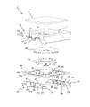
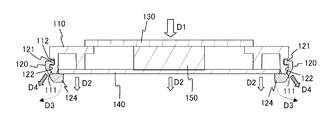
図9は、参考技術に係る撮像装置101を示す上面側斜視図である。
図10は、参考技術に係る、ストッパ120を取り外した状態の撮像装置101を示す底面側斜視図である。
図10は、参考技術に係る、ストッパ120を取り外した状態の撮像装置101を示す底面側斜視図である。
図11及び図12は、図9のXI-XI断面図及びXII-XII断面図である。
撮像装置101は、筐体110と、2つのストッパ120と、トップカバー130と、配線基板140と、撮像部150と、を備える。撮像装置101は、例えば、手のひらの静脈などの生体情報を撮像する生体認証装置である。
撮像装置101は、筐体110と、2つのストッパ120と、トップカバー130と、配線基板140と、撮像部150と、を備える。撮像装置101は、例えば、手のひらの静脈などの生体情報を撮像する生体認証装置である。
筐体110は、平面視正方形の枠状を呈する。筐体110の上面には、トップカバー130が配置されている。筐体110には、撮像部150が収容される。撮像部150は、不図示のレンズモジュールと、配線基板140に実装された不図示の撮像素子と、を有する。
ストッパ120は、筐体110との間に配線基板140を挟み込むことで、配線基板140を筐体110に固定する。ストッパ120は、筐体110の外周面である前後左右4つの面のうち互いに対向する2つの面に配置される。ストッパ120は、上記2つの面において、底部側の一部を構成する。ストッパ120は、筐体110の底面側から挿入されている。
筐体110は、筐体爪部111と、ストッパ爪部用凹部112と、差込部収容部113と、を有する。
ストッパ120は、ストッパ爪部121と、筐体爪部用凹部122と、差込部123と、基板押さえ部124と、を有する。
図10及び図11に示すように、筐体爪部111は、筐体爪部用凹部122に挿入される。ストッパ爪部121は、その上部に筐体爪部用凹部122が形成されるため、筐体爪部用凹部122よりも突出することで爪部として機能する。ストッパ爪部121は、筐体110の外周面に形成されたストッパ爪部用凹部112に挿入されることで、筐体110の外周面に係合する。
図10及び図12に示すように、差込部123は、ストッパ爪部121を挟んだ両側に設けられ、底面側に開口する差込部収容部113に挿入される。
基板押さえ部124は、配線基板140の底面(裏面)の周縁を押さえることで、筐体110との間に配線基板140を挟み込む。
上述の撮像装置101では、撮像対象物(例えば、手のひら)がトップカバー130に接触することなどにより、図11に示すようにトップカバー130に対し下方に荷重が加わった場合(矢印D1)、その力は配線基板140に加わる(矢印D2)。この際、図10及び図12に示す差込部123は、差込部収容部113に単に差し込まれているだけである。一方、図10及び図11に示すストッパ爪部121は、ストッパ爪部用凹部112に挿入され係合している。しかしながら、ストッパ120には、ストッパ爪部121を支点にして基板押さえ部124が配線基板140から離れる方向(矢印D3)に力が加わる。これにより、ストッパ120は、筐体110との間に配線基板140を挟み込む位置から外れてしまう(矢印D4)。
本発明は、このような点に鑑みてなされたものであり、ストッパを用いて簡素な構成で強固に配線基板を固定することができる撮像装置を提供することを目的とする。
開示の撮像装置は、撮像部と、前記撮像部を収容する筐体と、配線基板と、前記筐体との間に前記配線基板を挟み込むストッパと、を備え、前記筐体は、前記配線基板のうち前記撮像部側の表面とは反対側の裏面から突出する突出部を有し、前記ストッパは、前記筐体の外周面に係合する係合部と、前記筐体の前記突出部の内周面に引っ掛けられる引掛け部と、を有する。
開示の撮像装置によれば、ストッパを用いて簡素な構成で強固に配線基板を筐体に固定することができる。
以下、実施の形態に係る撮像装置1について、図面を参照しながら説明する。
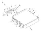
図1は、実施の形態に係る撮像装置1を示す上面側斜視図である。図2は、実施の形態に係る撮像装置1を示す上面側分解斜視図である。
図1は、実施の形態に係る撮像装置1を示す上面側斜視図である。図2は、実施の形態に係る撮像装置1を示す上面側分解斜視図である。
図3は、実施の形態に係る、ストッパ20を取り外した状態の撮像装置1を示す底面側斜視図である。
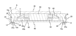
図4は、図1のIV-IV断面図である。図5は、図1のV-V断面図である。図6は、図1のVI-VI断面図である。
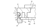
図7は、図4のA部拡大図である。図8は、図5のB部拡大図である。
図7は、図4のA部拡大図である。図8は、図5のB部拡大図である。
図2に示すように、撮像装置1は、筐体10と、2つのストッパ20と、トップカバー30と、配線基板40と、撮像部50と、導光体60と、遮光リング70と、複数の発光素子80と、複数の光検出器90と、を備える。
例えば、撮像装置1は、手のひらの静脈などの生体情報を撮像する生体認証装置或いはこの生体認証装置の一部となる生体認証用撮像装置として用いることができる。
図2及び図3に示すように、例えば、筐体10は、平面視において正方形状の枠状を呈する。
筐体10は、上面開口部11と、突出部12と、ストッパ爪部収容部13と、筐体爪部14と、差込部収容部15と、を有する。例えば、筐体10の各部の数は、突出部12は、1つのストッパ20ごとに1つ配置され、ストッパ爪部収容部13、筐体爪部14、及び差込部収容部15は、1つのストッパ20ごとに2つ配置される。
上面開口部11は、筐体10の上面においてトップカバー30よりも小さい正方形状に開口する。筐体10の底面は、上面開口部11よりも大きく開口している。
図4及び図7に示すように、突出部12は、配線基板40の裏面40bから突出する。この配線基板40の裏面40bは、配線基板40のうち撮像素子が実装される撮像部50側の表面40aとは反対側の面である。なお、筐体10の外周面10aである前後左右4つの面のうち、ストッパ20が配置されない2つの面の下端も、配線基板40の裏面40bから突出する。例えば、突出部12は、平面視において、筐体10の4辺のうち中央に設けられる。
図5及び図8に示すように、ストッパ爪部収容部13は、ストッパ爪部21の全体(ストッパ爪部21の筐体爪部14との係合部分、及びこの係合部分に対し外周面21a側に位置する部分)を収容する。尚、ストッパ爪部収容部13は、係合部収容部の一例である。また、ストッパ爪部21は、係合部の一例である。ストッパ爪部21及び筐体爪部14の詳細は、後述する。
筐体爪部14は、外周面10a側に突出し、ストッパ爪部21と係合する。筐体爪部14は、筐体爪部用凹部22に挿入される。なお、筐体爪部14は、外周面10aよりも内側に奥まって位置し、外周面10aからは突出しない。
図6に示すように、差込部収容部15は、筐体10の底面側に開口し、下方から差込部23が挿入される。
図2に示すように、ストッパ20は、ストッパ爪部21と、筐体爪部用凹部22と、差込部23と、基板押さえ部24と、突出部用凹部25と、を有する。例えば、ストッパ爪部21、筐体爪部用凹部22、及び差込部23は、2つずつ設けられる。ストッパ20は、筐体10との間に配線基板40を挟み込むことで、配線基板40を筐体10に固定する。
ストッパ20は、筐体10の外周面10aである前後左右4つの面のうち互いに対向する2つの面、すなわち配線基板40の互いに対向する2辺の各々に配置される。ストッパ20は、撮像装置1の外周面のうち底部側の一部を構成する。これにより、筐体10の外周面10aとストッパ20の外周面とで、撮像装置1の外周面が構成される。ストッパ20は、筐体10の底面側から挿入されている。ストッパ20は、本実施の形態のように対向して2つ配置されることが望ましい。尚、ストッパ20の数や配置場所(配置される辺)は限定されない。
図5及び図8に示すように、ストッパ爪部21は、筐体10の外周面10aに形成されたストッパ爪部収容部13に挿入されることで、筐体10の外周面10a(外周面10aに設けられた筐体爪部14)と係合する。尚、ストッパ爪部21は、係合部の一例である。また、ストッパ爪部21の外周面21aは、筐体10の外周面10aと同一面上に位置する。係合部の構成は、爪部により引っ掛けられる構成でなくともよい。例えば、係合部の構成は、筐体10の外周面に嵌合するように配置される構成などの他の構成であってもよい。
筐体爪部用凹部22は、ストッパ20の内周面側、すなわち撮像装置1の内部側に開口し、上記のとおり筐体爪部14が挿入される。
差込部23は、2つの筐体爪部用凹部22を挟んだ両端側に設けられている。例えば、差込部23は、板状を呈し、上記のとおり差込部収容部15に下方から挿入される。
基板押さえ部24は、配線基板40を押さえる位置にあり、筐体10との間で配線基板40を挟み込む。例えば、基板押さえ部24は、ストッパ20の長手方向の全長に亘って設けられ、配線基板40の1辺の全長に亘って配線基板40の裏面40bの周縁を押さえる。
突出部用凹部25も、筐体爪部用凹部22と同様にストッパ20の内周面側、すなわち撮像装置1の内部側に開口し、上記の突出部12が挿入される。突出部用凹部25の下端である引掛け溝25aは、突出部12の先端が挿入される。これにより、基板押さえ部24が突出部12の図7に示す内周面12aに引掛けられる。このように、例えば、引掛け溝25aが引掛け部として機能する。なお、引掛け溝25aは、平面視において、2つのストッパ爪部21の間に配置されている。
例えば、トップカバー30は、正方形状を呈し、筐体10の上面開口部11上に配置される。トップカバー30は、撮像対象物(例えば手のひら静脈)に向けて照射される照射光、及び撮像対象物からの反射光が透過するため、透光性のある材料から形成されている。
配線基板40は、撮像装置1の底側に配置されている。配線基板40は、CPUやメモリなどの部品が実装されることで、撮像用の制御部として機能する。また、撮像装置1が生体認証装置として用いられる場合、配線基板40は、生体認証用の制御部として機能することができる。
撮像部50は、レンズモジュール(不図示)と、配線基板140に実装された撮像素子(不図示)と、を有する。撮像部50は、筐体10に収容されている。
例えば、導光体60は、円環状を呈し、後述する発光素子80から出射される光を、トップカバー30を介して撮像対象物に導光する。
遮光リング70は、撮像部50と導光体60との間に配置され、撮像部50に外周面から光が入射するのを遮光する。
例えば、発光素子80は、LEDであり、配線基板40上に複数実装されている。発光素子80から出射される光は、上記のとおり、導光体60及びトップカバー30を通って撮像対象物に照射される。
光検出器90は、撮像部50の周囲において、配線基板40上に例えば4つ実装されている。光検出器90は、例えば、発光素子80の光量制御のために配置されている。
上述の撮像装置1では、図4及び図7に示すように、突出部12が引掛け溝25aに挿入されている。そのため、トップカバー30に対し下方に荷重が加わり、その力が配線基板40を介して基板押さえ部24に加わっても、基板押さえ部24が突出部12の内周面12aに接触することでストッパ20がストッパ爪部21を支点として配線基板40から離れる方向(図7の×を付された矢印参照)に移動しない。そのため、ストッパ20は、筐体10との間に配線基板40を挟み込む位置から外れず、強固に配線基板40を固定することができる。
以上説明した本実施の形態では、筐体10は、配線基板40のうち撮像部側の表面40aとは反対側の裏面40bから突出する突出部12を有する。また、ストッパ20は、筐体10の外周面10a(外周面10aに設けられたストッパ爪部収容部13)に係合するストッパ爪部(係合部)21と、筐体10の突出部12の内周面12aに引っ掛けられる引掛け溝(引掛け部)25aと、を有する。
そのため、ストッパ20は、基板押さえ部24が突出部12の内周面12aに接触することで、ストッパ爪部21を支点として配線基板40から離れる方向に移動するのを防ぐことができる。また、ストッパ20を用いた簡素な構成によって配線基板40を固定することができる。
よって、本実施の形態によれば、ストッパ20を用いて簡素な構成で強固に配線基板40を固定することができる。
また、本実施の形態では、引掛け部の一例である引掛け溝25aには、突出部12の先端が挿入される。そのため、より簡素な構成で配線基板40を固定することができる。
また、本実施の形態では、筐体10は、ストッパ爪部(係合部)21を収容するストッパ爪部収容部(係合部収容部)13を有し、ストッパ爪部21の外周面21aと筐体10の外周面10aとは、同一面上に位置する。これにより、ストッパ爪部21が筐体10の外周面10aから突出しないため、より簡素な構成で配線基板40を固定することができる。
また、本実施の形態では、係合部の一例がストッパ爪部21であり、筐体10は、ストッパ爪部21に係合する筐体爪部14を有する。そのため、より強固に配線基板40を固定することができる。また、爪部に加わる力がストッパ爪部21と筐体爪部14とに分散すること、及び、爪がストッパ20と筐体10との両方に設けられていることによって、爪部の引掛かり面積を小さくできるため、筐体10及びストッパ20が筐体10の外径方向に大きくなるのを抑えることができる。そのため、より簡素な構成で配線基板40を固定することができる。
また、本実施の形態では、ストッパ20は、複数のストッパ爪部21を有する。そのため、より強固に配線基板40を固定することができる。また、爪部に加わる力が複数のストッパ爪部21に分散することによって、爪部の引掛かり面積を小さくできるため、筐体10及びストッパ20が筐体10の外径方向に大きくなるのを抑えることができる。そのため、より簡素な構成で配線基板40を固定することができる。
また、本実施の形態では、ストッパ20は、配線基板40の互いに対向する2辺の各々に配置されている。そのため、簡素な構成で配線基板40を強固に固定することができる。
1 撮像装置
10 筐体
10a 外周面
11 上面開口部
12 突出部
12a 内周面
13 ストッパ爪部収容部
14 筐体爪部
15 差込部収容部
20 ストッパ
21 ストッパ爪部
21a 外周面
22 筐体爪部用凹部
23 差込部
24 基板押さえ部
25 突出部用凹部
25a 引掛け溝
30 トップカバー
40 配線基板
40a 表面
40b 裏面
50 撮像部
60 導光体
70 遮光リング
80 発光素子
90 光検出器
101 撮像装置
110 筐体
111 筐体爪部
112 ストッパ爪部用凹部
113 差込部収容部
120 ストッパ
121 ストッパ爪部
122 筐体爪部用凹部
123 差込部
124 基板押さえ部
130 トップカバー
140 配線基板
150 撮像部
Claims (6)
- 撮像部と、
前記撮像部を収容する筐体と、
配線基板と、
前記筐体との間に前記配線基板を挟み込むストッパと、を備え、
前記筐体は、前記配線基板のうち前記撮像部側の表面とは反対側の裏面から突出する突出部を有し、
前記ストッパは、前記筐体の外周面に係合する係合部と、前記筐体の前記突出部の内周面に引っ掛けられる引掛け部と、を有する、
ことを特徴とする撮像装置。 - 前記引掛け部は、前記突出部の先端が挿入される引掛け溝を有することを特徴とする請求項1記載の撮像装置。
- 前記筐体は、前記係合部を収容する係合部収容部を更に有し、
前記係合部の外周面と前記筐体の外周面とは同一面上に位置する、
ことを特徴とする請求項1又は請求項2記載の撮像装置。 - 前記ストッパの前記係合部は、ストッパ爪部を有し、
前記筐体は、前記ストッパ爪部に係合する筐体爪部を有する、
ことを特徴とする請求項1又は請求項2記載の撮像装置。 - 前記ストッパは、複数の前記係合部を有することを特徴とする請求項1又は請求項2記載の撮像装置。
- 前記ストッパは、前記配線基板の互いに対向する2辺の各々に配置されていることを特徴とする請求項1又は請求項2記載の撮像装置。
Priority Applications (4)
| Application Number | Priority Date | Filing Date | Title |
|---|---|---|---|
| EP13884992.2A EP3001671B1 (en) | 2013-05-23 | 2013-05-23 | Image pickup apparatus |
| PCT/JP2013/064357 WO2014188558A1 (ja) | 2013-05-23 | 2013-05-23 | 撮像装置 |
| JP2015517996A JP5933124B2 (ja) | 2013-05-23 | 2013-05-23 | 撮像装置 |
| US14/921,018 US10321027B2 (en) | 2013-05-23 | 2015-10-23 | Imaging apparatus |
Applications Claiming Priority (1)
| Application Number | Priority Date | Filing Date | Title |
|---|---|---|---|
| PCT/JP2013/064357 WO2014188558A1 (ja) | 2013-05-23 | 2013-05-23 | 撮像装置 |
Related Child Applications (1)
| Application Number | Title | Priority Date | Filing Date |
|---|---|---|---|
| US14/921,018 Continuation US10321027B2 (en) | 2013-05-23 | 2015-10-23 | Imaging apparatus |
Publications (1)
| Publication Number | Publication Date |
|---|---|
| WO2014188558A1 true WO2014188558A1 (ja) | 2014-11-27 |
Family
ID=51933141
Family Applications (1)
| Application Number | Title | Priority Date | Filing Date |
|---|---|---|---|
| PCT/JP2013/064357 WO2014188558A1 (ja) | 2013-05-23 | 2013-05-23 | 撮像装置 |
Country Status (4)
| Country | Link |
|---|---|
| US (1) | US10321027B2 (ja) |
| EP (1) | EP3001671B1 (ja) |
| JP (1) | JP5933124B2 (ja) |
| WO (1) | WO2014188558A1 (ja) |
Cited By (3)
| Publication number | Priority date | Publication date | Assignee | Title |
|---|---|---|---|---|
| DE102016101409A1 (de) * | 2016-01-27 | 2017-07-27 | Phoenix Contact Gmbh & Co. Kg | An eine Tragschiene ansetzbares Gehäuse zum Aufnehmen einer Elektronikbaugruppe |
| RU2669368C1 (ru) * | 2009-09-28 | 2018-10-11 | Амазон Текнолоджис, Инк. | Модульная система для центра обработки данных |
| CN109313378A (zh) * | 2016-06-15 | 2019-02-05 | 富士通先端科技株式会社 | 摄像装置 |
Families Citing this family (2)
| Publication number | Priority date | Publication date | Assignee | Title |
|---|---|---|---|---|
| WO2014196044A1 (ja) * | 2013-06-05 | 2014-12-11 | 富士通フロンテック株式会社 | 撮像装置 |
| WO2019150551A1 (ja) | 2018-02-02 | 2019-08-08 | 富士通フロンテック株式会社 | 撮像装置 |
Citations (3)
| Publication number | Priority date | Publication date | Assignee | Title |
|---|---|---|---|---|
| JP2534827Y2 (ja) | 1991-04-02 | 1997-05-07 | 日本建鐵株式会社 | 洗濯機の配線処理構造 |
| JP2001256487A (ja) | 2000-03-10 | 2001-09-21 | Omron Corp | 指紋照合機 |
| JP2011039275A (ja) * | 2009-08-11 | 2011-02-24 | Nidec Sankyo Corp | 光学ユニット |
Family Cites Families (12)
| Publication number | Priority date | Publication date | Assignee | Title |
|---|---|---|---|---|
| JPH0623375U (ja) * | 1992-08-24 | 1994-03-25 | オリンパス光学工業株式会社 | センサアッセンブリ |
| JPH0888482A (ja) * | 1994-09-19 | 1996-04-02 | Fujitsu Ten Ltd | 基板の固定構造 |
| US6496630B2 (en) | 2000-03-10 | 2002-12-17 | Omron Corporation | Fingerprint recognition device and fingerprint reading window construction |
| JP2003179818A (ja) * | 2001-12-10 | 2003-06-27 | Shinko Electric Ind Co Ltd | バックプレート、ハウジング及び撮像装置 |
| JP2003319216A (ja) * | 2002-04-18 | 2003-11-07 | Shinko Electric Ind Co Ltd | 撮像装置 |
| WO2004093005A1 (ja) * | 2003-04-15 | 2004-10-28 | Fujitsu Limited | 情報処理装置 |
| DE10344768B3 (de) * | 2003-09-26 | 2005-08-18 | Siemens Ag | Optisches Modul mit federndem Element zwischen Linsenhalter und Schaltungsträger und optisches System |
| US6979777B2 (en) * | 2003-10-15 | 2005-12-27 | Cooper Wiring Devices, Inc. | Weatherproof electrical enclosure having an adjustable-position cover |
| JP5007638B2 (ja) * | 2007-09-26 | 2012-08-22 | 富士通株式会社 | 電子機器 |
| JP4646960B2 (ja) * | 2007-09-28 | 2011-03-09 | 京セラ株式会社 | 固体撮像素子収納用パッケージ及び撮像装置 |
| JP5272636B2 (ja) * | 2008-10-10 | 2013-08-28 | ミツミ電機株式会社 | モジュールコネクタ |
| KR20110030091A (ko) * | 2009-09-17 | 2011-03-23 | 삼성전기주식회사 | 카메라 모듈 |
-
2013
- 2013-05-23 EP EP13884992.2A patent/EP3001671B1/en active Active
- 2013-05-23 WO PCT/JP2013/064357 patent/WO2014188558A1/ja active Application Filing
- 2013-05-23 JP JP2015517996A patent/JP5933124B2/ja active Active
-
2015
- 2015-10-23 US US14/921,018 patent/US10321027B2/en active Active
Patent Citations (3)
| Publication number | Priority date | Publication date | Assignee | Title |
|---|---|---|---|---|
| JP2534827Y2 (ja) | 1991-04-02 | 1997-05-07 | 日本建鐵株式会社 | 洗濯機の配線処理構造 |
| JP2001256487A (ja) | 2000-03-10 | 2001-09-21 | Omron Corp | 指紋照合機 |
| JP2011039275A (ja) * | 2009-08-11 | 2011-02-24 | Nidec Sankyo Corp | 光学ユニット |
Non-Patent Citations (1)
| Title |
|---|
| See also references of EP3001671A4 |
Cited By (5)
| Publication number | Priority date | Publication date | Assignee | Title |
|---|---|---|---|---|
| RU2669368C1 (ru) * | 2009-09-28 | 2018-10-11 | Амазон Текнолоджис, Инк. | Модульная система для центра обработки данных |
| US10779440B2 (en) | 2009-09-28 | 2020-09-15 | Amazon Technologies, Inc. | Modular system for data center |
| DE102016101409A1 (de) * | 2016-01-27 | 2017-07-27 | Phoenix Contact Gmbh & Co. Kg | An eine Tragschiene ansetzbares Gehäuse zum Aufnehmen einer Elektronikbaugruppe |
| US10085355B2 (en) | 2016-01-27 | 2018-09-25 | Phoenix Contact Gmbh & Co. Kg | Housing mountable on a mounting rail for receiving an electronics module |
| CN109313378A (zh) * | 2016-06-15 | 2019-02-05 | 富士通先端科技株式会社 | 摄像装置 |
Also Published As
| Publication number | Publication date |
|---|---|
| EP3001671B1 (en) | 2018-01-17 |
| EP3001671A4 (en) | 2017-01-18 |
| EP3001671A1 (en) | 2016-03-30 |
| US10321027B2 (en) | 2019-06-11 |
| JPWO2014188558A1 (ja) | 2017-02-23 |
| JP5933124B2 (ja) | 2016-06-08 |
| US20160044214A1 (en) | 2016-02-11 |
Similar Documents
| Publication | Publication Date | Title |
|---|---|---|
| JP5933124B2 (ja) | 撮像装置 | |
| EP3006998B1 (en) | Image pickup apparatus | |
| US9036220B2 (en) | Contact image sensing device | |
| US7615734B2 (en) | Image capture device | |
| US9886611B2 (en) | Stationary-type information code reading apparatus | |
| US10915007B2 (en) | Imaging apparatus | |
| JP6849827B2 (ja) | 撮像装置 | |
| JP6666440B2 (ja) | 撮像装置 | |
| JP6104860B2 (ja) | 電気機器のケーブル保持構造 | |
| CN107077620B (zh) | 光学指纹成像系统及光学组件 | |
| JP6778262B2 (ja) | 撮像装置 | |
| WO2016031435A1 (ja) | 光学情報読み取り装置 | |
| JP5976283B2 (ja) | 光学的情報読取装置 | |
| JP6458546B2 (ja) | 据置型情報コード読取装置 | |
| JP5967325B1 (ja) | 据置型情報コード読取装置 | |
| JP2013229774A (ja) | コンタクトイメージセンサーモジュール | |
| JP2007065043A (ja) | 光学ユニット |
Legal Events
| Date | Code | Title | Description |
|---|---|---|---|
| 121 | Ep: the epo has been informed by wipo that ep was designated in this application |
Ref document number: 13884992 Country of ref document: EP Kind code of ref document: A1 |
|
| ENP | Entry into the national phase |
Ref document number: 2015517996 Country of ref document: JP Kind code of ref document: A |
|
| WWE | Wipo information: entry into national phase |
Ref document number: 2013884992 Country of ref document: EP |
|
| NENP | Non-entry into the national phase |
Ref country code: DE |