US10915007B2 - Imaging apparatus - Google Patents

Imaging apparatus Download PDF

Info

Publication number
US10915007B2
US10915007B2 US16/195,136 US201816195136A US10915007B2 US 10915007 B2 US10915007 B2 US 10915007B2 US 201816195136 A US201816195136 A US 201816195136A US 10915007 B2 US10915007 B2 US 10915007B2
Authority
US
United States
Prior art keywords
lens unit
light
lens
imaging apparatus
wiring board
Prior art date
Legal status (The legal status is an assumption and is not a legal conclusion. Google has not performed a legal analysis and makes no representation as to the accuracy of the status listed.)
Active, expires
Application number
US16/195,136
Other versions
US20190086770A1 (en
Inventor
Akinori Tsujikawa
Current Assignee (The listed assignees may be inaccurate. Google has not performed a legal analysis and makes no representation or warranty as to the accuracy of the list.)
Fujitsu Frontech Ltd
Original Assignee
Fujitsu Frontech Ltd
Priority date (The priority date is an assumption and is not a legal conclusion. Google has not performed a legal analysis and makes no representation as to the accuracy of the date listed.)
Filing date
Publication date
Application filed by Fujitsu Frontech Ltd filed Critical Fujitsu Frontech Ltd
Assigned to FUJITSU FRONTECH LIMITED reassignment FUJITSU FRONTECH LIMITED ASSIGNMENT OF ASSIGNORS INTEREST (SEE DOCUMENT FOR DETAILS). Assignors: TSUJIKAWA, Akinori
Publication of US20190086770A1 publication Critical patent/US20190086770A1/en
Application granted granted Critical
Publication of US10915007B2 publication Critical patent/US10915007B2/en
Active legal-status Critical Current
Adjusted expiration legal-status Critical

Links

Images

Classifications

    • GPHYSICS
    • G03PHOTOGRAPHY; CINEMATOGRAPHY; ANALOGOUS TECHNIQUES USING WAVES OTHER THAN OPTICAL WAVES; ELECTROGRAPHY; HOLOGRAPHY
    • G03BAPPARATUS OR ARRANGEMENTS FOR TAKING PHOTOGRAPHS OR FOR PROJECTING OR VIEWING THEM; APPARATUS OR ARRANGEMENTS EMPLOYING ANALOGOUS TECHNIQUES USING WAVES OTHER THAN OPTICAL WAVES; ACCESSORIES THEREFOR
    • G03B15/00Special procedures for taking photographs; Apparatus therefor
    • G03B15/02Illuminating scene
    • G03B15/03Combinations of cameras with lighting apparatus; Flash units
    • G03B15/05Combinations of cameras with electronic flash apparatus; Electronic flash units
    • GPHYSICS
    • G03PHOTOGRAPHY; CINEMATOGRAPHY; ANALOGOUS TECHNIQUES USING WAVES OTHER THAN OPTICAL WAVES; ELECTROGRAPHY; HOLOGRAPHY
    • G03BAPPARATUS OR ARRANGEMENTS FOR TAKING PHOTOGRAPHS OR FOR PROJECTING OR VIEWING THEM; APPARATUS OR ARRANGEMENTS EMPLOYING ANALOGOUS TECHNIQUES USING WAVES OTHER THAN OPTICAL WAVES; ACCESSORIES THEREFOR
    • G03B15/00Special procedures for taking photographs; Apparatus therefor
    • G03B15/02Illuminating scene
    • G03B15/03Combinations of cameras with lighting apparatus; Flash units
    • GPHYSICS
    • G03PHOTOGRAPHY; CINEMATOGRAPHY; ANALOGOUS TECHNIQUES USING WAVES OTHER THAN OPTICAL WAVES; ELECTROGRAPHY; HOLOGRAPHY
    • G03BAPPARATUS OR ARRANGEMENTS FOR TAKING PHOTOGRAPHS OR FOR PROJECTING OR VIEWING THEM; APPARATUS OR ARRANGEMENTS EMPLOYING ANALOGOUS TECHNIQUES USING WAVES OTHER THAN OPTICAL WAVES; ACCESSORIES THEREFOR
    • G03B17/00Details of cameras or camera bodies; Accessories therefor
    • G03B17/02Bodies
    • GPHYSICS
    • G06COMPUTING; CALCULATING OR COUNTING
    • G06VIMAGE OR VIDEO RECOGNITION OR UNDERSTANDING
    • G06V40/00Recognition of biometric, human-related or animal-related patterns in image or video data
    • G06V40/10Human or animal bodies, e.g. vehicle occupants or pedestrians; Body parts, e.g. hands
    • G06V40/12Fingerprints or palmprints
    • G06V40/13Sensors therefor
    • G06V40/1312Sensors therefor direct reading, e.g. contactless acquisition
    • HELECTRICITY
    • H04ELECTRIC COMMUNICATION TECHNIQUE
    • H04NPICTORIAL COMMUNICATION, e.g. TELEVISION
    • H04N23/00Cameras or camera modules comprising electronic image sensors; Control thereof
    • GPHYSICS
    • G03PHOTOGRAPHY; CINEMATOGRAPHY; ANALOGOUS TECHNIQUES USING WAVES OTHER THAN OPTICAL WAVES; ELECTROGRAPHY; HOLOGRAPHY
    • G03BAPPARATUS OR ARRANGEMENTS FOR TAKING PHOTOGRAPHS OR FOR PROJECTING OR VIEWING THEM; APPARATUS OR ARRANGEMENTS EMPLOYING ANALOGOUS TECHNIQUES USING WAVES OTHER THAN OPTICAL WAVES; ACCESSORIES THEREFOR
    • G03B2215/00Special procedures for taking photographs; Apparatus therefor
    • G03B2215/05Combinations of cameras with electronic flash units
    • G03B2215/0503Built-in units
    • GPHYSICS
    • G03PHOTOGRAPHY; CINEMATOGRAPHY; ANALOGOUS TECHNIQUES USING WAVES OTHER THAN OPTICAL WAVES; ELECTROGRAPHY; HOLOGRAPHY
    • G03BAPPARATUS OR ARRANGEMENTS FOR TAKING PHOTOGRAPHS OR FOR PROJECTING OR VIEWING THEM; APPARATUS OR ARRANGEMENTS EMPLOYING ANALOGOUS TECHNIQUES USING WAVES OTHER THAN OPTICAL WAVES; ACCESSORIES THEREFOR
    • G03B2215/00Special procedures for taking photographs; Apparatus therefor
    • G03B2215/05Combinations of cameras with electronic flash units
    • G03B2215/0564Combinations of cameras with electronic flash units characterised by the type of light source
    • G03B2215/0575Ring shaped lighting arrangements
    • GPHYSICS
    • G03PHOTOGRAPHY; CINEMATOGRAPHY; ANALOGOUS TECHNIQUES USING WAVES OTHER THAN OPTICAL WAVES; ELECTROGRAPHY; HOLOGRAPHY
    • G03BAPPARATUS OR ARRANGEMENTS FOR TAKING PHOTOGRAPHS OR FOR PROJECTING OR VIEWING THEM; APPARATUS OR ARRANGEMENTS EMPLOYING ANALOGOUS TECHNIQUES USING WAVES OTHER THAN OPTICAL WAVES; ACCESSORIES THEREFOR
    • G03B2215/00Special procedures for taking photographs; Apparatus therefor
    • G03B2215/05Combinations of cameras with electronic flash units
    • G03B2215/0589Diffusors, filters or refraction means
    • G03B2215/0592Diffusors, filters or refraction means installed in front of light emitter

Definitions

  • the embodiments discussed herein are related to an imaging apparatus.
  • an imaging apparatus that includes a lens unit disposed on a wiring board, a plurality of light emitters disposed around the lens unit, and a light guide body disposed on an optical path specific to the plurality of light emitters has been used for a biometrics authentication apparatus that performs authentication based on biological information such as palm or finger veins, fingerprints, or pupil irises.
  • a known imaging apparatus further includes a light shield body called a hood that is disposed around a lens unit and blocks light that could enter the lens unit (see, for example, Japanese Laid-open Patent Publication No. 2008-233796).
  • a disclosed imaging apparatus includes an imaging element, a lens unit that focuses light on the imaging element, and a light source disposed around the lens unit, wherein the lens unit includes a shield part that projects over a region located around the lens unit and facing the light source so as to block stray light from the light source.
  • FIG. 1 is a plane view illustrating an imaging apparatus in accordance with an embodiment
  • FIG. 2 is a cross-sectional view taken on line II-II of FIG. 1 ;
  • FIG. 3 is an exploded perspective view illustrating an imaging apparatus in accordance with an embodiment
  • FIG. 4 is a perspective view illustrating a placed state of a polarization member in accordance with an embodiment
  • FIG. 5 is a perspective view illustrating an aperture in accordance with an embodiment
  • FIG. 6 is a perspective view illustrating a lens unit in accordance with an embodiment.
  • FIG. 7 is a cross-sectional view taken on VII-VII line of FIG. 6 .
  • the light shield body is disposed over a light guide body.
  • the distance between the plurality of light emitters and the lens unit is made to be short to accommodate the need to downsize an apparatus, light from the light emitters could be reflected from the light shield body or a wiring board and pass through a space between the light emitters and a hood and thus could enter the body of the lens unit.
  • a disclosed imaging apparatus is capable of preventing stray light from a light source disposed around a lens unit from entering the lens unit.
  • the imaging apparatus 1 emits light to a subject (e.g., a palm) and receives, at an imaging element 91 , the light reflected from the subject so as to capture an image.
  • the imaging element 91 is, for example, an image sensor.
  • FIG. 1 is a plane view illustrating the imaging apparatus 1 .
  • FIG. 2 is a cross-sectional view taken on line II-II of FIG. 1 .
  • FIG. 3 is an exploded perspective view illustrating the imaging apparatus 1 .
  • the imaging apparatus 1 includes an aperture 10 that corresponds to an exemplary framing member, a housing 20 , a top cover 30 , a wiring board 40 , a lens unit 50 , a light guide body 60 , a light shield body 70 , four polarization members 80 , an imaging element 91 , eight (a plurality of) illumination light emitters 92 that each correspond to an exemplary light source, and four ranging lenses 93 (see FIG. 3 ).
  • the imaging apparatus 1 is used as a biometrics authentication apparatus that performs authentication by capturing an image of a palm vein or as a portion of the biometrics authentication apparatus.
  • the imaging apparatus 1 may be an imaging apparatus that captures an image of another type of biological information such as finger veins, fingerprints, or pupil irises or may be an imaging apparatus that captures an image of a subject that is not biological information.
  • the aperture 10 has a rectangular frame shape (rectangular hollow shape) provided on the outer edge of the wiring board 40 in such a manner as to surround the lens unit 50 , the eight illumination light emitters 92 , and the like.
  • swelling parts 11 swelling toward a center on a lens-unit- 50 side are provided at four corners of the aperture 10 .
  • the swelling part 11 has provided therein a through bore (not illustrated) through which light emitted upward from a ranging light emitter (e.g., a LED) (not illustrated) mounted on the wiring board 40 passes.
  • the ranging lens 93 is disposed over the through bore.
  • the swelling parts 11 are each provided with four press-fit convex parts 11 a which project upward and into which the ranging lens 93 that assumes an X shape when seen in a plane view is pressed from above.
  • the expression “when seen in a plane view” in the present embodiment refers to a situation in which an object is seen in an optical-axis direction of the lens unit 50 from a side opposite to the imaging element 91 (direction A), and the position opposite to the position of the imaging element 91 may be expressed as “upward”, “above”, or “higher position” herein.
  • An engagement convex part lib that projects upward and that engages an engagement concave part 62 of the light guide body 60 depicted in FIG. 3 is provided at a portion of the swelling part 11 on the lens-unit- 50 side (the center side of the apparatus 1 ).
  • polarization plate supporting parts 12 which are positioned to sandwich the four swelling parts 11 and on which corners of the polarization members 80 are placed are provided on the inner surfaces of the aperture 10 .
  • four polarization plate supporting parts 13 on each of which a central portion of one edge of the polarization member 80 is placed are also provided on inner surfaces at the centers of four edges of the aperture 10 as seen in a plane view.
  • the housing 20 has a rectangular box shape without a top surface.
  • a concave top cover supporting portion 21 at a center side and an upper side on which the outer edge of the top cover 30 is placed is provided at an upper edge of the housing 20 .
  • the board supporting part 22 includes a supporting convex part 22 a having a rectangular solid shape projecting toward the center, and a guide convex part 22 b wherein portions of the guide convex part 22 b located at a higher position, i.e., portions of the guide convex part 22 b more distant from the supporting convex part 22 a , has a smaller amount of projection.
  • the guide convex part 22 b guides onto the supporting convex part 22 a the wiring board 40 inserted into the housing 20 from above together with the aperture 10 .
  • a plurality of board supporting parts 22 are provided so that the plurality of guide convex parts 22 b can hold the wiring board 40 in a surrounding manner.
  • the top cover 30 has a rectangular plate shape. As depicted in FIGS. 2-4 , the top cover 30 is formed of a translucent material for allow passage of light such as irradiation light emitted from the illumination light emitter (e.g., a LED) 92 toward a subject (e.g., a palm vein) or reflection light from the subject. As described above, the top cover 30 is placed on the top cover supporting portion 21 at the outer edge of the housing 20 and supported by the housing 20 at the top cover supporting portion 21 .
  • the illumination light emitter e.g., a LED
  • a subject e.g., a palm vein
  • the imaging element 91 , the lens unit 50 , and the eight illumination light emitters 92 are mounted on the wiring board 40 . Only one illumination light emitter 92 may be mounted when the illumination light emitter 92 assumes a ring shape surrounding the lens unit 50 .
  • the wiring board 40 Mounting a part such as a central processing unit (CPU) or a memory on the wiring board 40 allows the wiring board 40 to function as a controller for the imaging apparatus 1 .
  • the wiring board 40 may function as a controller for the biometrics authentication apparatus.
  • the lens unit 50 includes a lens body 51 and a lens supporting member 52 for supporting a lower portion of the lens body 51 , wherein the lens unit 50 focuses light on the imaging element 91 .
  • the lens body 51 and the lens supporting member 52 each assume a rectangular shape when seen in a plane view as depicted in FIG. 6 .
  • the lens supporting member 52 includes four blocking parts 52 a and four joined parts 52 b.
  • the four blocking parts 52 a are disposed on four side surfaces of the lens supporting member 52 and projects in such a manner as to assume an essentially triangular shape when seen in a plane view.
  • the four blocking parts 52 a each project over a region facing two of the eight illumination light emitters 92 .
  • the four blocking parts 52 a are provided on essentially the entirety of the side surfaces of the lens unit 50 .
  • the blocking part 52 a may project over a region located around the lens unit 50 and facing the illumination light emitter 92 , and, for example, may project above the illumination light emitter 92 .
  • the arrows depicted in FIG. 2 represent examples of stray light.
  • the stray light is reflected from a lower edge of the light shield body 70 and then from an upper surface of the wiring board 40 and travels toward the lens body 51 .
  • the blocking part 52 a blocks stray light from the illumination light emitter 92 (arrow).
  • the four blocking parts 52 a each have a corresponding polarization member 80 placed thereon.
  • another member such as the light shield body 70 may be placed on the blocking part 52 a.
  • the four joined parts 52 b project onto the wiring board 40 from portions of the side surfaces of the lens supporting member 52 as seen in a plane view at which the lens body 51 is not provided (e.g., from four corners).
  • FIG. 7 is a cross-sectional view taken on VII-VII line of FIG. 6 .
  • the joined parts 52 b are joined to the wiring board 40 by an adhesive 94 that corresponds to an exemplary joining material.
  • the adhesive 94 is an adhesive for electrical/electronic parts (e.g., a room temperature curing one-compound elastic adhesive based on silicone-modified polymer).
  • the lens unit 50 may be fixed to the wiring board 40 using another joining technique such as welding.
  • the light guide body 60 is toric as depicted in FIG. 3 and guides light emitted from the illumination light emitter 92 depicted in FIG. 2 to a subject through the top cover 30 .
  • the light guide body 60 desirably diffuses light emitted from the illumination light emitter 92 .
  • the top surface of the light guide body 60 is inclined downward from the inner surface of the body to the outer boundary.
  • the four flange parts 61 projecting in four directions are provided around the light guide body 60 .
  • the four flange parts 61 are inserted from above the aperture 10 in such a manner as to face the four inner surfaces of the aperture 10 without interfering with, or being interfered with by, the swelling parts 11 of the aperture 10 and are placed on the polarization members 80 .
  • the light guide body 60 is positioned for four orientations arranged at 90-degree intervals.
  • the four engagement concave parts 62 provided around the light guide body 60 each engage the engagement convex part lib of the swelling part 11 , as described above.
  • the light shield body 70 has a cylindrical shape as depicted in FIG. 3 and is located around the lens body 51 so as to block light as depicted in FIG. 2 .
  • a flange part 71 projects from the entirety of the upper edge of the side surface of the light shield body 70 .
  • the light shield body 70 is sent to the inside of the light guide body 60 from above, and the flange part 71 is placed on the light guide body 60 .
  • the four polarization members 80 are each placed on one blocking part 52 a of the lens unit 50 and on two polarization plate supporting parts 12 and one polarization plate supporting part 13 of the aperture 10 .
  • the four polarization members 80 are located on an optical path of light emitted from the illumination light emitter 92 , i.e., located above the illumination light emitter 92 .
  • the imaging apparatus 1 includes an imaging element 91 , a lens unit 50 that focuses light on the imaging element 91 , and eight illumination light emitters 92 that correspond to exemplary light sources disposed around the lens unit 50 .
  • the lens unit 50 includes a blocking part 52 a that projects over a region located around the lens unit 50 and facing the illumination light emitter 92 so as to block stray light from the illumination light emitter 92 .
  • stray light from the illumination light emitters 92 disposed around the lens unit 50 can be prevented from entering the lens body 51 within the lens unit 50 .
  • the imaging apparatus 1 further includes polarization members 80 disposed on an optical path of light emitted from the illumination light emitters 92 , and the polarization members 80 are placed on the blocking parts 52 a of the lens unit 50 .
  • the blocking part 52 a on which the polarization member 80 is placed as described above blocks stray light from the illumination light emitter 92 , so that the stray light can be prevented from entering the lens body 51 within the lens unit 50 without increasing the parts count with the configuration maintained simple.
  • the blocking part 52 a projects over a region located around the lens unit 50 and facing the illumination light emitter 92 , and hence the polarization member 80 can be prevented from shaking by increasing the area of the blocking part 52 a on which the polarization member 80 is placed.
  • the imaging apparatus 1 further includes an aperture 10 that corresponds to an exemplary framing member surrounding the lens unit 50 and the illumination light emitter 92 .
  • the aperture 10 includes polarization plate supporting parts 12 and 13 which are provided on the inner surfaces of the aperture 10 and on which the polarization members 80 are placed. Hence, the polarization members 80 can be reliably supported.
  • the lens unit 50 includes a lens body 51 and a lens supporting member 52 for supporting the lens body 51 , and blocking parts 52 a project from the side surfaces of the lens supporting member 52 . Hence, stray light can be prevented from entering the lens body 51 within the lens unit 50 with the configuration maintained simple.
  • the imaging apparatus 1 further includes an imaging element 91 , a lens unit 50 , and a wiring board 40 on which a illumination light emitter 92 is mounted
  • the lens unit 50 further includes joined parts 52 b projecting from the side surfaces of the lens unit 50 onto the wiring board 40 and joined to the wiring board 40 .
  • the adhesive 94 may be applied to the joined part 52 b in such a manner as to press the joined part 52 b downward to join the wiring board 40 and the lens unit 50 .
  • This allows the lens unit 50 to be strongly fixed to the wiring board 40 . In particular, this can enhance the resistance of a portable imaging apparatus 1 against dropping impacts or the like.
  • the present invention is not limited to the described embodiments and can be embodied by making changes to the components without departing the gist of the invention in an implementation phase.
  • Various inventions can be formed by combining, as appropriate, a plurality of components disclosed with reference to an embodiment. For example, all of the components indicated in an embodiment may be combined as appropriate. In this way, various changes or applications are possible without departing from the spirit of the invention.

Abstract

An imaging apparatus includes an imaging element, a lens unit that focuses light on the imaging element, and a light source disposed around the lens unit. The lens unit includes a blocking part that projects over a region located around the lens unit and facing the light source so as to block stray light from the light source.

Description

CROSS-REFERENCE TO RELATED APPLICATION
This application is continuation application of International Application PCT/JP2016/067143 filed on Jun. 8, 2016 and designated the U.S., the entire contents of which are incorporated herein by reference.
TECHNICAL FIELD
The embodiments discussed herein are related to an imaging apparatus.
BACKGROUND ART
Conventionally, an imaging apparatus that includes a lens unit disposed on a wiring board, a plurality of light emitters disposed around the lens unit, and a light guide body disposed on an optical path specific to the plurality of light emitters has been used for a biometrics authentication apparatus that performs authentication based on biological information such as palm or finger veins, fingerprints, or pupil irises. As such an imaging apparatus, a known imaging apparatus further includes a light shield body called a hood that is disposed around a lens unit and blocks light that could enter the lens unit (see, for example, Japanese Laid-open Patent Publication No. 2008-233796).
SUMMARY OF THE INVENTION
A disclosed imaging apparatus includes an imaging element, a lens unit that focuses light on the imaging element, and a light source disposed around the lens unit, wherein the lens unit includes a shield part that projects over a region located around the lens unit and facing the light source so as to block stray light from the light source.
BRIEF DESCRIPTION OF THE DRAWINGS
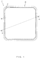
FIG. 1 is a plane view illustrating an imaging apparatus in accordance with an embodiment;
FIG. 2 is a cross-sectional view taken on line II-II of FIG. 1;
FIG. 3 is an exploded perspective view illustrating an imaging apparatus in accordance with an embodiment;
FIG. 4 is a perspective view illustrating a placed state of a polarization member in accordance with an embodiment;
FIG. 5 is a perspective view illustrating an aperture in accordance with an embodiment;
FIG. 6 is a perspective view illustrating a lens unit in accordance with an embodiment; and
FIG. 7 is a cross-sectional view taken on VII-VII line of FIG. 6.
EMBODIMENTS
In an imaging apparatus that includes the above-mentioned light shield body, the light shield body is disposed over a light guide body. Hence, especially when the distance between the plurality of light emitters and the lens unit is made to be short to accommodate the need to downsize an apparatus, light from the light emitters could be reflected from the light shield body or a wiring board and pass through a space between the light emitters and a hood and thus could enter the body of the lens unit.
A disclosed imaging apparatus is capable of preventing stray light from a light source disposed around a lens unit from entering the lens unit.
The following describes an imaging apparatus 1 in accordance with an embodiment by referring to the drawings.
The imaging apparatus 1 emits light to a subject (e.g., a palm) and receives, at an imaging element 91, the light reflected from the subject so as to capture an image. The imaging element 91 is, for example, an image sensor.
FIG. 1 is a plane view illustrating the imaging apparatus 1.
FIG. 2 is a cross-sectional view taken on line II-II of FIG. 1.
FIG. 3 is an exploded perspective view illustrating the imaging apparatus 1.
As depicted in FIGS. 2 and 3, the imaging apparatus 1 includes an aperture 10 that corresponds to an exemplary framing member, a housing 20, a top cover 30, a wiring board 40, a lens unit 50, a light guide body 60, a light shield body 70, four polarization members 80, an imaging element 91, eight (a plurality of) illumination light emitters 92 that each correspond to an exemplary light source, and four ranging lenses 93 (see FIG. 3).
The imaging apparatus 1 is used as a biometrics authentication apparatus that performs authentication by capturing an image of a palm vein or as a portion of the biometrics authentication apparatus. However, the imaging apparatus 1 may be an imaging apparatus that captures an image of another type of biological information such as finger veins, fingerprints, or pupil irises or may be an imaging apparatus that captures an image of a subject that is not biological information.
As depicted in FIGS. 2-4, the aperture 10 has a rectangular frame shape (rectangular hollow shape) provided on the outer edge of the wiring board 40 in such a manner as to surround the lens unit 50, the eight illumination light emitters 92, and the like. As depicted in FIGS. 4 and 5, swelling parts 11 swelling toward a center on a lens-unit-50 side are provided at four corners of the aperture 10.
The swelling part 11 has provided therein a through bore (not illustrated) through which light emitted upward from a ranging light emitter (e.g., a LED) (not illustrated) mounted on the wiring board 40 passes. The ranging lens 93 is disposed over the through bore.
As depicted in FIG. 5, the swelling parts 11 are each provided with four press-fit convex parts 11 a which project upward and into which the ranging lens 93 that assumes an X shape when seen in a plane view is pressed from above. The expression “when seen in a plane view” in the present embodiment refers to a situation in which an object is seen in an optical-axis direction of the lens unit 50 from a side opposite to the imaging element 91 (direction A), and the position opposite to the position of the imaging element 91 may be expressed as “upward”, “above”, or “higher position” herein.
An engagement convex part lib that projects upward and that engages an engagement concave part 62 of the light guide body 60 depicted in FIG. 3 is provided at a portion of the swelling part 11 on the lens-unit-50 side (the center side of the apparatus 1).
As depicted in FIG. 5, eight polarization plate supporting parts 12 which are positioned to sandwich the four swelling parts 11 and on which corners of the polarization members 80 are placed are provided on the inner surfaces of the aperture 10. Meanwhile, four polarization plate supporting parts 13 on each of which a central portion of one edge of the polarization member 80 is placed are also provided on inner surfaces at the centers of four edges of the aperture 10 as seen in a plane view.
As depicted in FIGS. 2 and 3, the housing 20 has a rectangular box shape without a top surface. A concave top cover supporting portion 21 at a center side and an upper side on which the outer edge of the top cover 30 is placed is provided at an upper edge of the housing 20.
As depicted in FIG. 3, a plurality of board supporting parts 22 on which the wiring board 40 is placed are provided on the inner surface of the housing 20. The board supporting part 22 includes a supporting convex part 22 a having a rectangular solid shape projecting toward the center, and a guide convex part 22 b wherein portions of the guide convex part 22 b located at a higher position, i.e., portions of the guide convex part 22 b more distant from the supporting convex part 22 a, has a smaller amount of projection. The guide convex part 22 b guides onto the supporting convex part 22 a the wiring board 40 inserted into the housing 20 from above together with the aperture 10. A plurality of board supporting parts 22 are provided so that the plurality of guide convex parts 22 b can hold the wiring board 40 in a surrounding manner.
As depicted in FIG. 3, the top cover 30 has a rectangular plate shape. As depicted in FIGS. 2-4, the top cover 30 is formed of a translucent material for allow passage of light such as irradiation light emitted from the illumination light emitter (e.g., a LED) 92 toward a subject (e.g., a palm vein) or reflection light from the subject. As described above, the top cover 30 is placed on the top cover supporting portion 21 at the outer edge of the housing 20 and supported by the housing 20 at the top cover supporting portion 21.
As depicted in FIG. 2, the imaging element 91, the lens unit 50, and the eight illumination light emitters 92 are mounted on the wiring board 40. Only one illumination light emitter 92 may be mounted when the illumination light emitter 92 assumes a ring shape surrounding the lens unit 50.
Mounting a part such as a central processing unit (CPU) or a memory on the wiring board 40 allows the wiring board 40 to function as a controller for the imaging apparatus 1. When the imaging apparatus 1 is used as a biometrics authentication apparatus, the wiring board 40 may function as a controller for the biometrics authentication apparatus.
As depicted in FIG. 2, the lens unit 50 includes a lens body 51 and a lens supporting member 52 for supporting a lower portion of the lens body 51, wherein the lens unit 50 focuses light on the imaging element 91. In one example, the lens body 51 and the lens supporting member 52 each assume a rectangular shape when seen in a plane view as depicted in FIG. 6.
As depicted in FIG. 6, the lens supporting member 52 includes four blocking parts 52 a and four joined parts 52 b.
As depicted in FIG. 4, the four blocking parts 52 a are disposed on four side surfaces of the lens supporting member 52 and projects in such a manner as to assume an essentially triangular shape when seen in a plane view. The four blocking parts 52 a each project over a region facing two of the eight illumination light emitters 92. Accordingly, the four blocking parts 52 a are provided on essentially the entirety of the side surfaces of the lens unit 50. When seen in a plane view, the blocking part 52 a may project over a region located around the lens unit 50 and facing the illumination light emitter 92, and, for example, may project above the illumination light emitter 92.
The arrows depicted in FIG. 2 represent examples of stray light. The stray light is reflected from a lower edge of the light shield body 70 and then from an upper surface of the wiring board 40 and travels toward the lens body 51.
The blocking part 52 a blocks stray light from the illumination light emitter 92 (arrow).
As depicted in FIG. 2, the four blocking parts 52 a each have a corresponding polarization member 80 placed thereon. When the polarization member 80 is omitted from the imaging apparatus 1, another member such as the light shield body 70 may be placed on the blocking part 52 a.
As depicted in FIG. 6, the four joined parts 52 b project onto the wiring board 40 from portions of the side surfaces of the lens supporting member 52 as seen in a plane view at which the lens body 51 is not provided (e.g., from four corners).
FIG. 7 is a cross-sectional view taken on VII-VII line of FIG. 6. As depicted in FIG. 7, the joined parts 52 b are joined to the wiring board 40 by an adhesive 94 that corresponds to an exemplary joining material. The adhesive 94 is an adhesive for electrical/electronic parts (e.g., a room temperature curing one-compound elastic adhesive based on silicone-modified polymer). Instead of causing the joined parts 52 b to adhere using the adhesive 94, the lens unit 50 may be fixed to the wiring board 40 using another joining technique such as welding.
The light guide body 60 is toric as depicted in FIG. 3 and guides light emitted from the illumination light emitter 92 depicted in FIG. 2 to a subject through the top cover 30. The light guide body 60 desirably diffuses light emitted from the illumination light emitter 92. The top surface of the light guide body 60 is inclined downward from the inner surface of the body to the outer boundary.
Four rectangular-plate-shaped flange parts 61 projecting in four directions are provided around the light guide body 60. The four flange parts 61 are inserted from above the aperture 10 in such a manner as to face the four inner surfaces of the aperture 10 without interfering with, or being interfered with by, the swelling parts 11 of the aperture 10 and are placed on the polarization members 80. As a result, the light guide body 60 is positioned for four orientations arranged at 90-degree intervals. In a space between every pair of two adjacent flange parts 61 of the light guide body 60, the four engagement concave parts 62 provided around the light guide body 60 each engage the engagement convex part lib of the swelling part 11, as described above.
The light shield body 70 has a cylindrical shape as depicted in FIG. 3 and is located around the lens body 51 so as to block light as depicted in FIG. 2. A flange part 71 projects from the entirety of the upper edge of the side surface of the light shield body 70. The light shield body 70 is sent to the inside of the light guide body 60 from above, and the flange part 71 is placed on the light guide body 60.
As described above, the four polarization members 80 are each placed on one blocking part 52 a of the lens unit 50 and on two polarization plate supporting parts 12 and one polarization plate supporting part 13 of the aperture 10. As a result, as depicted in FIG. 2, the four polarization members 80 are located on an optical path of light emitted from the illumination light emitter 92, i.e., located above the illumination light emitter 92.
In the embodiment described above, the imaging apparatus 1 includes an imaging element 91, a lens unit 50 that focuses light on the imaging element 91, and eight illumination light emitters 92 that correspond to exemplary light sources disposed around the lens unit 50. The lens unit 50 includes a blocking part 52 a that projects over a region located around the lens unit 50 and facing the illumination light emitter 92 so as to block stray light from the illumination light emitter 92.
The blocking part 52 a that projects over a region located around the lens unit 50 and facing the illumination light emitter 92 blocks, as described above, stray light from the illumination light emitter 92 and thus can prevent the stray light from entering the lens body 51 within the lens unit 50. Hence, in the embodiment, stray light from the illumination light emitters 92 disposed around the lens unit 50 can be prevented from entering the lens body 51 within the lens unit 50.
In the embodiment, the imaging apparatus 1 further includes polarization members 80 disposed on an optical path of light emitted from the illumination light emitters 92, and the polarization members 80 are placed on the blocking parts 52 a of the lens unit 50. The blocking part 52 a on which the polarization member 80 is placed as described above blocks stray light from the illumination light emitter 92, so that the stray light can be prevented from entering the lens body 51 within the lens unit 50 without increasing the parts count with the configuration maintained simple. In addition, the blocking part 52 a projects over a region located around the lens unit 50 and facing the illumination light emitter 92, and hence the polarization member 80 can be prevented from shaking by increasing the area of the blocking part 52 a on which the polarization member 80 is placed.
In the embodiment, the imaging apparatus 1 further includes an aperture 10 that corresponds to an exemplary framing member surrounding the lens unit 50 and the illumination light emitter 92. The aperture 10 includes polarization plate supporting parts 12 and 13 which are provided on the inner surfaces of the aperture 10 and on which the polarization members 80 are placed. Hence, the polarization members 80 can be reliably supported.
In the embodiment, the lens unit 50 includes a lens body 51 and a lens supporting member 52 for supporting the lens body 51, and blocking parts 52 a project from the side surfaces of the lens supporting member 52. Hence, stray light can be prevented from entering the lens body 51 within the lens unit 50 with the configuration maintained simple.
In the embodiment, the imaging apparatus 1 further includes an imaging element 91, a lens unit 50, and a wiring board 40 on which a illumination light emitter 92 is mounted, and the lens unit 50 further includes joined parts 52 b projecting from the side surfaces of the lens unit 50 onto the wiring board 40 and joined to the wiring board 40. Hence, the adhesive 94 may be applied to the joined part 52 b in such a manner as to press the joined part 52 b downward to join the wiring board 40 and the lens unit 50. This allows the lens unit 50 to be strongly fixed to the wiring board 40. In particular, this can enhance the resistance of a portable imaging apparatus 1 against dropping impacts or the like.
The present invention is not limited to the described embodiments and can be embodied by making changes to the components without departing the gist of the invention in an implementation phase. Various inventions can be formed by combining, as appropriate, a plurality of components disclosed with reference to an embodiment. For example, all of the components indicated in an embodiment may be combined as appropriate. In this way, various changes or applications are possible without departing from the spirit of the invention.

Claims (4)

The invention claimed is:
1. An imaging apparatus comprising:
an imaging element;
a lens unit that includes a lens body and a lens supporting member for supporting the lens body and that focuses light on the imaging element; and
a light source disposed around the lens unit,
a light shield body located around the lens body so as to block light; and
a wiring board on which the imaging element, the lens unit, and the light source are mounted, wherein
the lens unit includes a blocking part that projects over a region located around the lens supporting member and facing the light source so as to block stray light from the light source, the stray light being reflected from the light shield body and the wiring board and traveling toward the lens body.
2. The imaging apparatus of claim 1, further comprising:
a polarization member disposed on an optical path of light emitted from the light source, wherein
the polarization member is placed on the blocking part of the lens unit.
3. The imaging apparatus of claim 2, further comprising:
a framing member surrounding the lens unit and the light source, wherein
the framing member includes a polarization plate supporting part which is provided on an inner surface of the framing member and on which the polarization member is placed.
4. The imaging apparatus of claim 1, wherein
the lens unit further includes a joined part projecting from a side surface of the lens supporting member onto the wiring board and joined to the wiring board.
US16/195,136 2016-06-08 2018-11-19 Imaging apparatus Active 2036-12-03 US10915007B2 (en)

Applications Claiming Priority (1)

Application Number Priority Date Filing Date Title
PCT/JP2016/067143 WO2017212600A1 (en) 2016-06-08 2016-06-08 Imaging device

Related Parent Applications (1)

Application Number Title Priority Date Filing Date
PCT/JP2016/067143 Continuation WO2017212600A1 (en) 2016-06-08 2016-06-08 Imaging device

Publications (2)

Publication Number Publication Date
US20190086770A1 US20190086770A1 (en) 2019-03-21
US10915007B2 true US10915007B2 (en) 2021-02-09

Family

ID=60578498

Family Applications (1)

Application Number Title Priority Date Filing Date
US16/195,136 Active 2036-12-03 US10915007B2 (en) 2016-06-08 2018-11-19 Imaging apparatus

Country Status (5)

Country Link
US (1) US10915007B2 (en)
EP (1) EP3470917B1 (en)
JP (1) JP6616502B2 (en)
CN (1) CN109154763B (en)
WO (1) WO2017212600A1 (en)

Families Citing this family (4)

* Cited by examiner, † Cited by third party
Publication number Priority date Publication date Assignee Title
WO2017216902A1 (en) * 2016-06-15 2017-12-21 富士通フロンテック株式会社 Image pickup device
CN107734226A (en) * 2017-10-24 2018-02-23 捷开通讯(深圳)有限公司 Filming apparatus and electronic equipment for electronic equipment
CN110730288A (en) * 2019-10-29 2020-01-24 维沃移动通信有限公司 Camera module and electronic equipment
US20230412904A1 (en) * 2020-10-08 2023-12-21 Sony Semiconductor Solutions Corporation In-vehicle camera, control apparatus and control method for in-vehicle camera, and in-vehicle camera system

Citations (9)

* Cited by examiner, † Cited by third party
Publication number Priority date Publication date Assignee Title
US4070096A (en) * 1976-08-02 1978-01-24 Joseph Jasgur Polarized cosmetic mirror
JPH057320A (en) 1991-02-01 1993-01-14 Matsushita Electric Works Ltd Intercom slave machine provided with camera
US6033087A (en) 1996-12-26 2000-03-07 Patlite Corporation LED illuminating device for providing a uniform light spot
JP2002077694A (en) 2000-08-30 2002-03-15 Kyocera Corp Ir camera
EP1830307A1 (en) 2006-03-03 2007-09-05 Fujitsu Limited Image capturing apparatus
US20080230681A1 (en) 2007-03-23 2008-09-25 Fujitsu Limited Image capture device
JP2010055023A (en) 2008-08-29 2010-03-11 Toshiba Teli Corp Industrial endoscope
US20130128104A1 (en) * 2011-11-22 2013-05-23 Cognex Corporation Camera system with exchangeable illumination assembly
US20140160300A1 (en) 2012-12-07 2014-06-12 Sercomm Corporation Network camera

Family Cites Families (1)

* Cited by examiner, † Cited by third party
Publication number Priority date Publication date Assignee Title
KR101090965B1 (en) * 2011-07-18 2011-12-08 주식회사 하이소닉 Motion sensing switch

Patent Citations (13)

* Cited by examiner, † Cited by third party
Publication number Priority date Publication date Assignee Title
US4070096A (en) * 1976-08-02 1978-01-24 Joseph Jasgur Polarized cosmetic mirror
JPH057320A (en) 1991-02-01 1993-01-14 Matsushita Electric Works Ltd Intercom slave machine provided with camera
US6033087A (en) 1996-12-26 2000-03-07 Patlite Corporation LED illuminating device for providing a uniform light spot
JP2002077694A (en) 2000-08-30 2002-03-15 Kyocera Corp Ir camera
EP1830307A1 (en) 2006-03-03 2007-09-05 Fujitsu Limited Image capturing apparatus
CN101030014A (en) 2006-03-03 2007-09-05 富士通株式会社 Image capturing apparatus
US20070206114A1 (en) 2006-03-03 2007-09-06 Fujitsu Limited Image capturing apparatus
JP2007235863A (en) 2006-03-03 2007-09-13 Fujitsu Ltd Imaging apparatus
US20080230681A1 (en) 2007-03-23 2008-09-25 Fujitsu Limited Image capture device
JP2008233796A (en) 2007-03-23 2008-10-02 Fujitsu Ltd Imaging apparatus
JP2010055023A (en) 2008-08-29 2010-03-11 Toshiba Teli Corp Industrial endoscope
US20130128104A1 (en) * 2011-11-22 2013-05-23 Cognex Corporation Camera system with exchangeable illumination assembly
US20140160300A1 (en) 2012-12-07 2014-06-12 Sercomm Corporation Network camera

Non-Patent Citations (5)

* Cited by examiner, † Cited by third party
Title
EESR issued in corresponding EP patent application No. 16904635.6, dated May 8, 2019.
ISR issued in Int'l. Application No. PCT/JP2016/067143, dated Sep. 13, 2016.
Office action issued in corresponding Chinese patent application No. 201680086147.4 (full machine translation).
Office action issued in corresponding Japanese patent application No. 2018-522247, dated Aug. 6, 2019 (with full machine translation).
Written Opinion of the International Searching Authority of PCT/JP2016/067143 (partial English translation).

Also Published As

Publication number Publication date
JPWO2017212600A1 (en) 2018-11-29
CN109154763B (en) 2021-03-19
WO2017212600A1 (en) 2017-12-14
EP3470917B1 (en) 2021-05-12
US20190086770A1 (en) 2019-03-21
EP3470917A4 (en) 2019-06-05
EP3470917A1 (en) 2019-04-17
JP6616502B2 (en) 2019-12-04
CN109154763A (en) 2019-01-04

Similar Documents

Publication Publication Date Title
US10915007B2 (en) Imaging apparatus
US10019615B2 (en) Fingerprint identification apparatus and manufacturing method thereof
US9736343B2 (en) Imaging apparatus with top cover
US7615734B2 (en) Image capture device
US10914883B2 (en) Imaging apparatus including illuminating light guide with positioning features
US11314034B2 (en) Imaging apparatus
US20190305180A1 (en) Light emitting package
US10321027B2 (en) Imaging apparatus
US10921684B2 (en) Imaging apparatus
KR102111633B1 (en) Lens and light emitting package comprising the same
JP2001216496A (en) Fingerprint image input device

Legal Events

Date Code Title Description
AS Assignment

Owner name: FUJITSU FRONTECH LIMITED, JAPAN

Free format text: ASSIGNMENT OF ASSIGNORS INTEREST;ASSIGNOR:TSUJIKAWA, AKINORI;REEL/FRAME:047544/0692

Effective date: 20180927

FEPP Fee payment procedure

Free format text: ENTITY STATUS SET TO UNDISCOUNTED (ORIGINAL EVENT CODE: BIG.); ENTITY STATUS OF PATENT OWNER: LARGE ENTITY

STPP Information on status: patent application and granting procedure in general

Free format text: DOCKETED NEW CASE - READY FOR EXAMINATION

STPP Information on status: patent application and granting procedure in general

Free format text: RESPONSE TO NON-FINAL OFFICE ACTION ENTERED AND FORWARDED TO EXAMINER

STCF Information on status: patent grant

Free format text: PATENTED CASE