WO2014185512A1 - Lampe pour véhicule - Google Patents
Lampe pour véhicule Download PDFInfo
- Publication number
- WO2014185512A1 WO2014185512A1 PCT/JP2014/063046 JP2014063046W WO2014185512A1 WO 2014185512 A1 WO2014185512 A1 WO 2014185512A1 JP 2014063046 W JP2014063046 W JP 2014063046W WO 2014185512 A1 WO2014185512 A1 WO 2014185512A1
- Authority
- WO
- WIPO (PCT)
- Prior art keywords
- mounting
- attachment
- lens
- positioning
- attached
- Prior art date
Links
Images


Classifications
-
- F—MECHANICAL ENGINEERING; LIGHTING; HEATING; WEAPONS; BLASTING
- F21—LIGHTING
- F21S—NON-PORTABLE LIGHTING DEVICES; SYSTEMS THEREOF; VEHICLE LIGHTING DEVICES SPECIALLY ADAPTED FOR VEHICLE EXTERIORS
- F21S41/00—Illuminating devices specially adapted for vehicle exteriors, e.g. headlamps
- F21S41/10—Illuminating devices specially adapted for vehicle exteriors, e.g. headlamps characterised by the light source
- F21S41/14—Illuminating devices specially adapted for vehicle exteriors, e.g. headlamps characterised by the light source characterised by the type of light source
- F21S41/141—Light emitting diodes [LED]
- F21S41/143—Light emitting diodes [LED] the main emission direction of the LED being parallel to the optical axis of the illuminating device
-
- F—MECHANICAL ENGINEERING; LIGHTING; HEATING; WEAPONS; BLASTING
- F21—LIGHTING
- F21S—NON-PORTABLE LIGHTING DEVICES; SYSTEMS THEREOF; VEHICLE LIGHTING DEVICES SPECIALLY ADAPTED FOR VEHICLE EXTERIORS
- F21S41/00—Illuminating devices specially adapted for vehicle exteriors, e.g. headlamps
- F21S41/20—Illuminating devices specially adapted for vehicle exteriors, e.g. headlamps characterised by refractors, transparent cover plates, light guides or filters
- F21S41/25—Projection lenses
- F21S41/255—Lenses with a front view of circular or truncated circular outline
-
- F—MECHANICAL ENGINEERING; LIGHTING; HEATING; WEAPONS; BLASTING
- F21—LIGHTING
- F21S—NON-PORTABLE LIGHTING DEVICES; SYSTEMS THEREOF; VEHICLE LIGHTING DEVICES SPECIALLY ADAPTED FOR VEHICLE EXTERIORS
- F21S41/00—Illuminating devices specially adapted for vehicle exteriors, e.g. headlamps
- F21S41/20—Illuminating devices specially adapted for vehicle exteriors, e.g. headlamps characterised by refractors, transparent cover plates, light guides or filters
- F21S41/29—Attachment thereof
- F21S41/295—Attachment thereof specially adapted to projection lenses
-
- F—MECHANICAL ENGINEERING; LIGHTING; HEATING; WEAPONS; BLASTING
- F21—LIGHTING
- F21S—NON-PORTABLE LIGHTING DEVICES; SYSTEMS THEREOF; VEHICLE LIGHTING DEVICES SPECIALLY ADAPTED FOR VEHICLE EXTERIORS
- F21S45/00—Arrangements within vehicle lighting devices specially adapted for vehicle exteriors, for purposes other than emission or distribution of light
- F21S45/10—Protection of lighting devices
-
- F—MECHANICAL ENGINEERING; LIGHTING; HEATING; WEAPONS; BLASTING
- F21—LIGHTING
- F21S—NON-PORTABLE LIGHTING DEVICES; SYSTEMS THEREOF; VEHICLE LIGHTING DEVICES SPECIALLY ADAPTED FOR VEHICLE EXTERIORS
- F21S45/00—Arrangements within vehicle lighting devices specially adapted for vehicle exteriors, for purposes other than emission or distribution of light
- F21S45/40—Cooling of lighting devices
- F21S45/47—Passive cooling, e.g. using fins, thermal conductive elements or openings
- F21S45/48—Passive cooling, e.g. using fins, thermal conductive elements or openings with means for conducting heat from the inside to the outside of the lighting devices, e.g. with fins on the outer surface of the lighting device
-
- F—MECHANICAL ENGINEERING; LIGHTING; HEATING; WEAPONS; BLASTING
- F21—LIGHTING
- F21S—NON-PORTABLE LIGHTING DEVICES; SYSTEMS THEREOF; VEHICLE LIGHTING DEVICES SPECIALLY ADAPTED FOR VEHICLE EXTERIORS
- F21S45/00—Arrangements within vehicle lighting devices specially adapted for vehicle exteriors, for purposes other than emission or distribution of light
- F21S45/40—Cooling of lighting devices
- F21S45/49—Attachment of the cooling means
Definitions
- the present invention relates to a vehicular lamp.
- the present invention relates to a vehicular lamp that can securely attach a member to be attached such as a lens holder or a reflector to an attachment member such as a heat sink member without using a screw or the like.
- a conventional vehicular lamp is formed by attaching a lens holder to a heat sink by forming a locking projection on the lens holder, forming a locking hole in the heat sink, and locking the locking projection in one direction to the locking hole. is there.
- the conventional vehicular lamp is for locking the locking projection in one direction to the locking hole, there is a backlash in the direction opposite to the one direction in which the locking projection and the locking hole are locked to each other. May occur.
- the problem to be solved by the present invention is that play may occur in the conventional vehicular lamp.
- a first invention includes a light source, an attachment member, and a member to be attached.
- the attachment member and the member to be attached are provided with attachment structures for attaching the member to be attached to the attachment member, respectively.
- Mounting hook that attaches the mounting member to the mounting member by sandwiching the mounting portion between at least one of the mounting member or the mounting member by inserting it into the portion and moving it in a direction crossing the insertion direction It is comprised from the part.
- the attachment hook portion is provided to face at least one of the attachment member and the attached member, and the sandwiching portion that sandwiches the attachment portion, and at least of the attachment member or the attachment member
- a positioning part that is provided in the movement direction between one of the other and the sandwiching part, and that determines a position in the movement direction by contacting an edge on the movement direction side of the insertion space part; It is characterized by.
- At least one of the attachment member and the attached member has a positioning portion in contact with an edge of the insertion space portion on the movement direction side, and the insertion space portion on the movement direction side.
- a retaining portion is provided that contacts the edge opposite to the edge to determine a position opposite to the moving direction and stops the attachment hook portion from coming off the attachment portion.
- At least two positioning portions and edges on the moving direction side of the insertion space portions with which the positioning portions abut are provided in a direction intersecting the insertion direction and the moving direction. It is characterized by that.
- the fifth invention is characterized in that the moving direction is a direction intersecting the direction of gravity.
- a sixth invention includes an attachment member to which a light source is attached, a member to be attached, and an attachment structure for attaching the member to be attached to the attachment member, and the attachment structure is at least one of the attachment member and the member to be attached.
- a mounting hook portion for mounting the mounted member on the mounting member by sandwiching the mounting portion between at least one of the mounting member and the mounted member by moving in the direction.
- the plurality of light sources are located inside the plurality of mounting structures, and the distance between each mounting structure and the light source is substantially equal in the front view. It is characterized in.
- At least one mounting hook portion is provided in a direction intersecting the moving direction, and is provided to rise from at least one of the mounting member or the mounted member in the insertion direction.
- the vehicular lamp according to the present invention is configured such that at least one of the attachment member and the attached member is attached to at least one of the attachment member and the attached member (hereinafter simply referred to as “the other of the attachment member and the attached member”). And the attachment hook portion, and the attachment member is attached to the attachment member by being sandwiched from both directions. For this reason, it is possible to eliminate backlash in the direction opposite to the direction in which the mounting portion, the mounting member, and the other of the mounted members are in contact with each other by the mutual contact between the mounting portion and the mounting hook portion. On the other hand, backlash in the direction opposite to the direction in which the attachment portion and the attachment hook portion abut each other can be eliminated by mutual contact between the attachment portion, the attachment member, and the other of the attached members. In this way, the attached member can be securely attached to the attachment member without play without using a screw or the like.
- FIG. 1 is a perspective view of a lamp unit illustrating an embodiment of a vehicular lamp according to the present invention as seen from an obliquely front side (front surface, front side) in an exploded state.
- FIG. 2 is an exploded perspective view of the lens and the lens holder of the lamp unit, as viewed from obliquely above the back surface (back surface, rear surface).
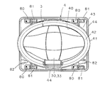
- FIG. 3 is a front view showing a lens of the lamp unit.
- FIG. 4 is a rear view showing the lens of the lamp unit.
- FIG. 5 is a perspective view showing the lens holder of the lamp unit as seen from below the back side.
- FIG. 6 is a front view showing an assembled state of the lens of the lamp unit and the lens holder.
- FIG. 1 is a perspective view of a lamp unit illustrating an embodiment of a vehicular lamp according to the present invention as seen from an obliquely front side (front surface, front side) in an exploded state.
- FIG. 2 is an exploded perspective view of the
- FIG. 7 is a rear view showing an assembled state of the lens of the lamp unit and the lens holder.
- FIG. 8 is a front view showing a state before the lens and the lens holder are attached to the heat sink member.
- 9 is a cross-sectional view taken along line IX-IX in FIG.
- FIG. 10 is a front view illustrating a state in which the lens and the lens holder are attached to the heat sink member.
- 11 is a cross-sectional view taken along line XI-XI in FIG.
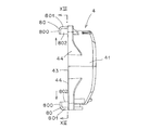
- FIG. 12 is a side view showing the lens holder (as viewed in the direction of arrow XII in FIG. 2).
- FIG. 13 is an explanatory diagram (a view taken along the line XIII-XIII in FIG.
- FIG. 12 showing the relative positional relationship between the mounting structure (mounting hook portion) and the light source.
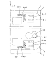
- FIG. 14 is an explanatory view showing a mounting hook portion and a retaining portion of the lens holder, a mounting portion of the heat sink member, and an insertion space portion.
- FIG. 15 is an explanatory diagram showing a state before the lens holder is attached to the heat sink member.
- FIG. 16 is an explanatory view showing a state in which the lens holder is attached to the heat sink member.
- FIG. 17 is a partially enlarged explanatory view showing positioning holes and positioning pins.
- FIG. 18 is an explanatory view showing a modification of the vehicular lamp according to the present invention.
- front, rear, upper, lower, left, and right are front, rear, upper, lower, left, and right when the vehicular lamp according to the present invention is mounted on a vehicle.
- FIG. 1 denotes a vehicular lamp (for example, a vehicular headlamp such as a headlamp) according to this embodiment.
- the vehicular lamp 1 is mounted on both left and right ends of the front portion of the vehicle.
- the vehicular lamp 1 includes a lamp housing (not shown), a lamp lens (not shown), a semiconductor light source 2 as a light source, a lens 3, a lens holder 4, And a mounting member (hereinafter referred to as a “heat sink member”) 5 that also serves as a heat sink member.
- the semiconductor light source 2 is attached to the heat sink member 5 as an attachment member.
- the lens 3 and the lens holder 4 are members to be attached to the heat sink member 5 as an attachment member.
- the semiconductor-type light source 2, the lens 3, the lens holder 4, and the heat sink member 5 constitute a lamp unit.
- the lamp housing and the lamp lens define a lamp chamber (not shown).
- the lamp units 2, 3, 4, and 5 are disposed in the lamp chamber, and are provided with a vertical optical axis adjustment mechanism (not shown) and a horizontal optical axis adjustment mechanism (not shown). Are attached to the lamp housing.
- the semiconductor-type light source 2 is a self-luminous semiconductor-type light source such as an LED, an OEL, or an OLED (organic EL) in this example.
- the semiconductor light source 2 includes a light emitting chip (LED chip) having a light emitting surface, a package (LED package) in which the light emitting chip is sealed with a sealing resin member, and a substrate 20 on which the package is mounted. ing.
- the semiconductor-type light source 2 is positioned and attached to the light source attachment portion 50 of the heat sink member 5 via the light source holder 21.
- the light emitting surface of the light emitting chip faces the front side of the reference optical axis (reference axis) Z of the lens 3.
- the center of the light emitting surface of the light emitting chip is located at or near the reference focal point of the lens 3 and on or near the reference optical axis Z of the lens 3.
- X, Y, and Z constitute an orthogonal coordinate (XYZ orthogonal coordinate system).
- the X axis is a horizontal axis passing through the center of the light emitting surface of the light emitting chip.
- the outside of the vehicle that is, the left side is the + direction (X axis direction), and the right side is ⁇ Direction (direction opposite to the X-axis direction).
- the Y axis is a vertical axis in the vertical direction passing through the center of the light emitting surface of the light emitting chip.
- the upper side is the + direction (Y axis direction)
- the lower side is the ⁇ direction (Y axis).
- the Z-axis is a normal line (perpendicular) passing through the center of the light-emitting surface of the light-emitting chip, that is, an axis in the front-rear direction orthogonal to the X-axis and the Y-axis. (Z-axis direction), and the rear side is the-direction (the direction opposite to the Z-axis direction).
- the reference optical axis Z and the Z axis of the lens 3 match or substantially match.
- the light source holder 21 is positioned and attached to the light source holder attaching portion 51 of the heat sink member 5 by a screw 22.
- the light source holder 21 is provided with a holder portion for holding the semiconductor light source 2 on the heat sink member 5, a terminal for supplying power to the semiconductor light source 2, a circuit, and a connector.
- the lens 3 includes a lens portion 30, an auxiliary lens portion (additional lens portion), and a flange portion 31.
- the lens part 30 has a non-circular shape when viewed from the front. That is, the lens 3 is a deformed lens.
- the lens 3 is made of a resin member.
- the lens 3 has the largest thickness at or near the reference optical axis Z, and the thickness decreases as the distance from the reference optical axis Z increases. For this reason, the center of gravity of the lens 3 is located at or near the reference optical axis Z.
- the lens 3 is positioned and held by the lens holder 4.
- the lens 3 is positioned and attached to the heat sink member 5 via the lens holder 4.
- the lens 3 irradiates the light from the semiconductor light source 2 to the outside through the lens unit 30 and the auxiliary lens unit.
- the lens unit 30 includes an incident surface 32 on the back side of the lens 3 and an exit surface 33 on the front side of the lens 3.
- the incident surface 32 forms a convex curved surface protruding toward the semiconductor-type light source 2, a concave curved surface recessed toward the opposite side of the semiconductor-type light source 2, or a flat surface.
- the entrance surface 32 is composed of a free-form surface, a quadric surface, a compound quadratic surface, a combination surface thereof, or a flat surface.
- the exit surface 33 forms a convex curved surface that protrudes on the opposite side to the semiconductor light source 2.
- the exit surface 33 is composed of a free-form surface, a quadric surface, a composite quadratic surface, or a combination thereof.
- the auxiliary lens portion is integrally provided at the lower center portion of the peripheral edge portion of the lens portion 30.
- the auxiliary lens unit includes an incident surface, a reflecting surface, and an exit surface.
- the flange portion 31 is integrally provided on the peripheral portion (entire periphery or part) of the lens portion 30 and the auxiliary lens portion.
- the rear surface of the flange portion 31 is formed of a free curved surface or a plane almost in the same manner as the incident surface 32.
- the front surface of the flange portion 31 is formed of a free-form surface in substantially the same manner as the emission surface 33.
- the front view shape of the edge (end surface, outer surface) of the flange portion 31 is a non-circular shape similar to the front view shape of the lens portion 30.
- the lens holder 4 is made of a member having elasticity and a thermal conductivity lower than that of the heat sink member 5 (high thermal resistance) such as a resin member. As shown in FIGS. 1, 2, and 5 to 7, the lens holder 4 has a cylindrical structure having an opening 40 in which the lens portion 30 is disposed at the center.
- the lens holder 4 includes a holding cylinder portion 41, a holding edge portion 42, a mounting plate portion 43, and a reinforcing rib portion 44.
- the lens holder 4 positions and holds the lens 3.
- the lens holder 4 is positioned and attached to the heat sink member 5.
- the lens 3 is positioned and attached to the heat sink member 5 via the lens holder 4.
- the holding cylinder portion 41 has a cylindrical shape.
- the front-view shape of the holding cylinder portion 41 is a non-circular shape similar to the front-view shape of the lens 3.
- the inner peripheral surface of the holding cylinder portion 41 is slightly larger than the outer peripheral surface of the edge of the flange portion 31 of the lens 3.
- the holding edge portion 42 has a flange shape, and is integrally provided from the one end (front end) of the holding cylinder portion 41 to the inside of the holding cylinder portion 41.
- the opening 40 is provided at the center of the holding edge 42.
- the front view shape of the inner peripheral surface of the holding edge portion 42 (that is, the edge of the opening portion 40) is a non-circular shape similar to the front view shape of the lens portion 30 of the lens 3.
- the inner peripheral surface of the holding edge portion 42 is slightly smaller than the outer peripheral surface of the edge of the flange portion 31 of the lens 3 and slightly larger than the boundary between the lens portion 30 and the flange portion 31.
- the mounting plate portion 43 has a plate shape, and is integrally provided on the upper outer side and the lower outer side of the holding cylinder portion 41 from the upper portion and the lower portion of the other end (back side end) of the holding cylinder portion 41. Yes.
- a front view shape of the outer shape of the mounting plate portion 43 is substantially rectangular. That is, a substantially middle portion between the left and right sides of the mounting plate portion 43 is a part of the left and right side portions of the holding cylinder portion 41 and has a curved shape.
- the reinforcing rib portion 44 has a rib shape and is integrally provided on the front side from the four sides of the mounting plate portion 43.
- the reinforcing rib 44 has a substantially rectangular shape when viewed from the front, almost the same as the shape of the mounting plate 43 when viewed from the front. That is, the upper reinforcing rib portion 44 has a U-shape with an opening at the bottom, and the lower reinforcing rib portion 44 has a U-shape with an opening at the top.
- the heat sink member 5 is an attachment member to which the semiconductor light source 2 and the lens holder 4 are attached, and the lens 3 is attached via the lens holder 4.
- the heat sink member 5 radiates heat generated by the semiconductor light source 2 to the outside.
- the heat sink member 5 is made of, for example, an aluminum die casting or a resin member having thermal conductivity.
- the heat sink member 5 includes a vertical plate portion 52 and a plurality of vertical plate-shaped fin portions 53 provided integrally on one surface (back surface) of the vertical plate portion 52. Yes.
- a substantially cross-shaped recess 54 is provided at the center of the mounting surface (planar or substantially flat) of the other surface (front surface) of the vertical plate portion 52 of the heat sink member 5.
- the light source mounting portion 50 is provided at the center of the bottom surface of the recess 54.
- the light source holder mounting portion 51 is provided on the bottom surface of the recess 54 and around the light source mounting portion 50.
- the lens 3 and the lens holder 4 are respectively provided with positioning portions.
- the positioning portion determines the position of the lens 3 with respect to the lens holder 4.
- the positioning unit includes an XY positioning unit, a rotation positioning unit, and a Z positioning unit.
- the XY positioning unit determines the position of the lens 3 in the X-axis direction and the Y-axis direction. As shown in FIGS. 2 and 7, the XY positioning portion contacts the convex portion 60 protruding in the Y-axis direction and the Z-axis direction, and two locations (two points or two straight lines) on the side surface of the convex portion 60. And a contact surface 61.
- the convex portion 60 of the XY positioning portion is provided at a location on the lower right side of the inner peripheral surface of the holding cylinder portion 41 of the lens holder 4.
- the convex part 60 of the XY positioning part should just be comprised from the curved surface part in which the said contact surface 61 carries out two-point point contact or linear contact.
- a pin may be used.
- the contact surface 61 of the XY positioning portion is provided at a position on the lower right side of the flange portion 31 of the lens 3 so as to correspond to the convex portion 60.
- the contact surface 61 of the XY positioning portion is composed of two V-shaped planes or one curved surface.
- the rotational positioning portion determines a position in the rotational direction on the XY plane with the XY positioning portion of the lens 3 as the center (center of the curved surface portion of the convex portion 60).
- the rotational positioning portion includes a convex portion 62 that projects in the Y-axis direction and the Z-axis direction, and a contact surface 63 that contacts one place (one point or one straight line) at the top of the convex portion 62. And is composed of.
- the convex portion 62 of the rotational positioning portion is provided at a lower left portion of the inner peripheral surface of the holding cylinder portion 41 of the lens holder 4.
- the convex part 62 of the rotation positioning part may be a part of the curved part where the contact surface 63 is in point contact or linear contact.
- a pin may be used.
- the contact surface 63 of the rotational positioning portion is provided at a location on the lower left side of the flange portion 31 of the lens 3 so as to correspond to the convex portion 62.
- the contact surface 63 of the rotational positioning unit is a flat surface or a curved surface.
- the Z positioning portion determines the position of the reference optical axis Z (Z-axis direction) of the lens 3.
- the Z positioning portion of the lens holder 4 includes a pressing portion 70 and a positioning surface 71.
- the Z positioning portion of the lens 3 includes a receiving convex portion 72 and a positioning convex portion 73.
- the pressing portion 70 is provided so as to protrude to the inside of the lens holder 4 at three locations, that is, the upper center of the holding cylinder portion 41 of the lens holder 4 and the left and right sides of the lower portion. Concave notches 74 are provided on the left and right sides and the front side of the pressing portion 70 (the boundary between the holding cylinder portion 41 and the holding edge portion 42). As a result, the pressing portion 70 has elasticity in a direction perpendicular to or substantially perpendicular to the reference optical axis Z (Z-axis direction) of the lens 3. The pressing portion 70 is for pressing the lens 3 in the Z-axis direction.
- the positioning surface 71 is provided on the inner surface (rear surface) at three locations, that is, the upper center of the holding edge portion 42 of the lens holder 4 and both the left and right sides of the lower portion, respectively, so as to face the pressing portion 70.
- the positioning surface 71 is a surface that is orthogonal or substantially orthogonal to the reference optical axis Z (Z-axis direction) of the lens 3.
- the positioning convex portion 73 is a surface of the flange portion 31 of the lens 3 that faces the positioning surface 71, and the positioning surface 71 is provided at three locations, the upper center of the flange portion 31 and the lower left and right sides. It is provided corresponding to.
- the positioning convex portion 73 has a minute truncated cone shape. That is, the top of the positioning convex portion 73 is formed of a minute plane that is orthogonal or substantially orthogonal to the reference optical axis Z. As a result, the positioning convex portion 73 comes into contact with the positioning surface 71 in a minute plane by the pressing force of the pressing portion 70 received by the receiving convex portion 72.
- the positioning projection 73 may have a shape other than the frustoconical shape, for example, a columnar shape, or a hemispherical shape that contacts the positioning surface 71 at a point. It may be.
- the receiving convex portion 72 is a surface of the flange portion 31 of the lens 3 that faces the pressing portion 70, and the pressing portion 70 is provided at three locations, the upper center of the flange portion 31 and the lower left and right sides. It is provided corresponding to.
- the receiving convex part 72 has a convex shape along the edge of the flange part 31.
- the outer surface of the receiving convex portion 72 forms a curved surface. As a result, the receiving convex portion 72 receives the pressing force of the pressing portion 70 linearly or substantially linearly along the edge of the flange portion 31.
- the lower two are the convex portion 60 and the contact surface of the XY positioning portion. 61 and the convex portion 62 and the contact surface 63 of the rotational positioning portion.
- the three pressing parts 70, the positioning surface 71, the receiving convex part 72, and the positioning convex part 73 of the Z positioning part are arranged at positions that surround the center of gravity of the lens 3.
- the lens 3 and the lens holder 4 are provided with gap portions, respectively.
- the gap filling portion fills a gap between the convex portion 60 and the contact surface 61 of the XY positioning portion and a gap between the convex portion 62 and the contact surface 63 of the rotational positioning portion. It is.
- the gap filling portion has a position of the lens 3 determined by the XY positioning portion (position in the X-axis direction and Y-axis direction) and a position determined by the rotational positioning portion (rotation direction on the XY plane). Position) without any play.
- the gap portion of the lens 3 includes a receiving surface 64 as shown in FIGS.
- the receiving surfaces 64 are respectively provided at two positions on the upper left and right sides of the edge (end surface) of the flange portion 31 of the lens 3.
- the two receiving surfaces 64 are each composed of a plane parallel or substantially parallel to the X axis.
- the two receiving surfaces 64 are arranged on the left and right sides of the receiving convex portion 72 and the positioning convex portion 73 of the Z positioning portion of the upper one lens 3.
- the gap portion of the lens holder 4 includes a protrusion 65.
- the protrusions 65 are portions on the holding edge portion 42 side of the holding cylinder portion 41 of the lens holder 4, and are respectively provided at two locations on the upper left and right sides. Slits (holes or grooves) 66 are provided on the left and right sides of the two protrusions 65, respectively.
- the protrusions 65 have elasticity in a direction perpendicular to or substantially perpendicular to the Z-axis direction (the Y-axis direction and the direction opposite to the Y-axis direction).
- the two protrusions 65 are disposed on both the left and right sides of the pressing portion 70 and the positioning surface 71 of the Z positioning portion of the one upper lens holder 4.
- the convex portion 60 and the contact surface 61 of the XY positioning portion, the convex portion 62 and the contact surface 63 of the rotational positioning portion, and the two receiving surfaces 64 and the protrusion 65 of the gap portion The lens 3 is disposed at a position surrounding the center of gravity.
- the lens holder 4 and the heat sink member 5 are provided with attachment structures, respectively.
- the lens holder 4 holding the lens 3 is securely mounted to the heat sink member 5 without using a screw without looseness.
- the mounting structure of the lens holder 4 includes a mounting hook portion 80 and a retaining portion 81.
- the attachment hook portion 80 and the retaining portion 81 are provided on one surface (rear surface) of each of the four corners of the attachment plate portion 43 of the lens holder 4.
- the attachment hook portion 80 is disposed on the opposite side to the X-axis direction with respect to the retaining portion 81.
- Positioning holes 82 are provided in the lower corners of the mounting plate 43 of the lens holder 4.
- FIG. 14A is an explanatory diagram showing the mounting hook portion 80 and the retaining portion 81 of the lens holder 4.
- the mounting structure of the heat sink member 5 includes a surface mounting portion 83 as a mounting portion having a mounting hole portion 84 as an insertion space portion, and The rear surface mounting portion 830 is configured.
- the attachment hole 84 is provided at the four corners of the vertical plate portion 52 of the heat sink member 5 so as to correspond to the attachment hook portion 80 and the retaining portion 81.
- the front surface attachment portion 83 and the rear surface attachment portion 830 correspond to the attachment hook portion 80 on the other surface (front surface) and one surface (rear surface) of the edge of the attachment hole portion 84 in the direction opposite to the X-axis direction, respectively. Is provided.
- Positioning pins 85 are provided corresponding to the positioning holes 82 at the lower corners of the vertical plate portion 52 of the heat sink member 5.
- FIG. 14B is an explanatory view showing the surface mounting portion 83 and the mounting hole portion 84 of the heat sink member 5.
- the semiconductor light source 2 is located inside the four sets of the mounting structures (that is, inside the quadrilateral connecting the four sets of the mounting structures). To do. In front view, the distances between the mounting structures and the semiconductor light source 2 are substantially equal.
- Each of the mounting structures is on the same plane or substantially the same plane (the surface of the mounting plate portion 43, the surface of the vertical plate portion 52) orthogonal to or substantially orthogonal to the reference optical axis Z of the lens 3.
- the attachment hook portion 80 is inserted into the attachment hole portion 84 in a direction opposite to the Z-axis direction and moved in a direction crossing the insertion direction, that is, in a direction opposite to the X-axis direction, thereby causing the heat sink member 5 to move to the heat sink member 5.
- the lens holder 4 is attached. That is, the mounting hook portion 80 is located between the front surface mounting portion 83 and the rear surface mounting portion 830 between the mounting plate portion 43 of the lens holder 4 in both directions, that is, in the insertion direction (the direction opposite to the Z-axis direction).
- the lens holder 4 is attached to the heat sink member 5 by being sandwiched from the direction opposite to the insertion direction (Z-axis direction).
- the moving direction (the direction opposite to the X-axis direction, see the solid arrow in FIG. 13) is a direction that intersects the gravity direction (the direction opposite to the Y-axis direction).
- the mounting hook portion 80 includes a rising plate portion 802, a sandwiching plate portion 800, and a reinforcing plate portion 801. In the vicinity of the mounting hook portion 80, an opening 803 for molding the rising plate portion 802, the sandwiching plate portion 800, and the reinforcing plate portion 801 is provided.
- the rising plate portion 802 rises from the edge of the opening 803 on the X-axis direction side in the insertion direction and is provided integrally with the mounting plate portion 43 of the lens holder 4.
- the sandwiching plate portion 800 is a sandwiching portion, and extends integrally from the rising plate portion 802 in the moving direction.
- the sandwiching plate portion 800 and the rising plate portion 802 have an L shape, that is, a hook shape.
- the sandwiching plate portion 800 is provided to face the edge of the opening 803. As shown in FIG. 11, the sandwiching plate portion 800 sandwiches the front surface mounting portion 83 and the rear surface mounting portion 830 of the vertical plate portion 52 of the heat sink member 5 between the edges of the opening 803. .
- the reinforcing plate portion 801 is integrally provided on one side of the rising plate portion 802 and the sandwiching plate portion 800 and on one side that is symmetrical with respect to the moving direction, in this example. .
- the upper reinforcing plate portion 801 is provided between the outer edge of the opening 803 in the Y-axis direction and the sandwiching plate portion 800.
- the lower reinforcing plate portion 801 is provided between the outer edge of the opening 803 in the direction opposite to the Y-axis direction and the sandwiching plate portion 800.
- the reinforcing plate portion 801 is integrally connected to the rising plate portion 802 in an L shape.
- the reinforcing plate portion 801 reinforces the strength of the sandwiching plate portion 800 and the rising plate portion 802. As shown in FIG. 16, the reinforcing plate portion 801 is guided in the moving direction by an edge 840 on the moving direction side of the mounting hole portion 84. That is, the reinforcing plate portion 801 has a reinforcing function and a guide function.
- a U-shaped notch 810 is provided on three sides of the retaining portion 81 other than the attachment hook portion 80 side.
- the retaining portion 81 has elasticity in the Z-axis direction and the direction opposite to the Z-axis direction.
- the distal end portion of the retaining portion 81 (the end portion opposite to the mounting hook portion 80) has a lance shape.
- the retaining portion 81 is formed on the mounting hole portion 84 in a state where the tip of the reinforcing plate portion 801 is guided by the edge 840 on the moving direction side of the mounting hole portion 84. It is located at the edge 841 opposite to the edge 840 on the moving direction side and abuts. As a result, the lens holder 4 moves (slides) in the X-axis direction with respect to the heat sink member 5 between the retaining portion 81 and the edge 841 opposite to the moving direction side edge 840 of the mounting hole portion 84. Is to regulate. That is, the retaining portion 81 and the edge 841 opposite to the moving direction side edge 840 of the mounting hole portion 84 prevent the mounting hook portion 80 from coming out of the front surface mounting portion 83 and the back surface mounting portion 830. It is something to stop.
- the mounting hole 84 includes a rectangular hole into which the mounting hook 80 can be inserted, and a direction opposite to the X-axis direction from the hole. And a slit portion provided.
- the slit portion is provided with an inclined edge 840 on the moving direction side where the reinforcing plate portion 801 is guided.
- the hole is provided with the opposite edge 841.
- the reinforcing plate portion 801 and the edge 840 on the moving direction side are provided at least two in the insertion direction and the direction intersecting the moving direction, that is, the Y-axis direction and the direction opposite to the Y-axis direction.
- a total of four lens holders 4 and two heat sink members 5 are provided above and below the left side of the lens holder 4 and two above and below the right side.
- the positioning hole 82 has a large-diameter hole opposite to the X-axis direction, a small-diameter hole on the X-axis direction side, and a communication where the large-diameter hole and the small-diameter hole communicate with each other. Part. A part of the communication part has a distance substantially equal to the diameter of the small diameter hole.
- the diameter of the positioning pin 85 is smaller than the diameter of the large diameter hole and slightly larger than the diameter of the small diameter hole.
- a long hole 820 is provided in the mounting plate portion 43 of the lens holder 4 and on one side edge of the communicating portion of the positioning hole 82.
- a portion of the positioning hole 82 between the communicating portion and the elongated hole 820 constitutes an elastic portion 822 having elasticity in the Y-axis direction and the direction opposite to the Y-axis direction.
- Both end portions of the elastic portion 822 are connected to the mounting plate portion 43 of the lens holder 4 via connection portions 821, respectively. That is, the elastic portion 822 forms a double-supported beam structure by the connection portions 821 at both ends.
- the vehicular lamp 1 according to this embodiment is configured as described above, and the assembly will be described below.
- the semiconductor-type light source 2 is set on the light source mounting portion 50 of the heat sink member 5. Further, the light source holder 21 is attached to the light source holder attaching portion 51 of the heat sink member 5 with the screw 22. As a result, the semiconductor light source 2 is attached to the heat sink member 5 via the light source holder 21.
- the exit surface 33 of the lens 3 is positioned on the front side, and the holding edge 42 of the lens holder 4 is positioned on the front side.
- the lens 3 is inserted into the holding cylinder portion 41 of the lens holder 4 in the Z-axis direction.
- the receiving convex portion 72 and the positioning convex portion 73 of the Z positioning portion on the lens 3 side are sandwiched between the pressing portion 70 and the positioning surface 71 of the Z positioning portion on the lens holder 4 side, and the pressing portion. It is fixed in the Z-axis direction by a pressing force of 70.
- the lens 3 is fixedly held by the lens holder 4 in the Z-axis direction and the direction opposite to the Z-axis direction in a state where the positions in the Z-axis direction and the direction opposite to the Z-axis direction are determined.
- the contact surface 61 of the XY positioning portion on the lens 3 side comes into contact with two places on the side surface of the convex portion 60 of the XY positioning portion on the lens holder 4 side.
- the contact surface 63 of the rotation positioning portion on the lens 3 side contacts one place on the side surface of the convex portion 62 of the rotation positioning portion on the lens holder 4 side.
- the projection 65 of the gap portion on the lens holder 4 side is perpendicular to or substantially perpendicular to the Z-axis direction on the receiving surface 64 of the gap portion on the lens 3 side (Y-axis direction). Elastic contact in the opposite direction).
- the lens 3 is attached to the lens holder 4 in the X-axis direction, the opposite direction to the X-axis direction, the Y-axis direction, the opposite direction to the Y-axis direction, and the rotation direction (XY centered on the center of the curved surface portion of the convex portion 60).
- the position in the clockwise direction and the counterclockwise direction on the surface is fixed and held in each direction.
- the attachment hook portion 80 of the lens holder 4 holding the lens 3 is inserted into the attachment hole portion 84 of the heat sink member 5 in the direction opposite to the Z-axis direction.
- the positioning pin 85 of the heat sink member 5 is inserted into the large-diameter hole of the positioning hole 82 of the lens holder 4 holding the lens 3 in the direction opposite to the Z-axis direction.
- the lens holder 4 holding the lens 3 is moved (slid) in the direction opposite to the X-axis direction with respect to the heat sink member 5.
- the front surface mounting portion 83 and the back surface mounting portion 830 of the heat sink member 5 are located between the sandwiching plate portion 800 of the mounting hook portion 80 and the mounting plate portion 43 of the lens holder 4. It is caught. Further, the corner portion of the tip end portion of the reinforcing plate portion 801 of the attachment hook portion 80 is guided by the inclined surface of the edge 840 on the moving direction side of the attachment hole portion 84. Further, the retaining portion 81 is positioned and abutted on the edge 841 on the opposite side of the mounting hole portion 84. For this reason, it is possible to restrict the lens holder 4 from moving (sliding) in the X-axis direction with respect to the heat sink member 5. Furthermore, the positioning pin 85 elastically contacts the edge of the communicating portion of the positioning hole 82.
- the lens holder 4 holding the lens 3 is applied to the heat sink member 5 in the direction opposite to the X-axis direction and the X-axis direction, the direction opposite to the Y-axis direction and the Y-axis direction, the direction opposite to the Z-axis direction and the Z-axis direction. Fixed against.
- the vehicular lamp 1 according to this embodiment is assembled.
- the vehicular lamp 1 according to this embodiment is configured as described above, and the operation thereof will be described below.
- the light-emitting chip of the semiconductor light source 2 is turned on. Then, most of the light emitted from the light emitting chip directly enters the lens unit 30 from the incident surface 32 of the lens unit 30 of the lens 3. At this time, the light distribution of the incident light is controlled on the incident surface 32. Incident light that enters the lens unit 30 exits from the exit surface 33 of the lens unit 30. At this time, the emitted light is subjected to light distribution control on the emission surface 33.
- the light emitted from the lens unit 30 is irradiated in front of the vehicle as a predetermined light distribution pattern, for example, a low beam light distribution pattern or a high beam light distribution pattern.
- a small portion of the light emitted from the light emitting chip is directly incident on the auxiliary lens portion from the incident surface of the auxiliary lens portion of the lens 3.
- incident light is subjected to light distribution control on the incident surface.
- Incident light that enters the auxiliary lens unit is reflected by the reflecting surface of the auxiliary lens unit.
- the reflected light is subjected to light distribution control on the reflecting surface.
- This reflected light is emitted from the emission surface of the auxiliary lens unit.
- the emitted light is subjected to light distribution control on the emission surface.
- Light emitted from the auxiliary lens unit is irradiated outside the vehicle as a predetermined auxiliary light distribution pattern.
- heat generated in the light emitting chip of the semiconductor light source 2 is radiated to the outside through the heat sink member 5.
- the vehicular lamp 1 according to this embodiment is configured and operated as described above, and the effects thereof will be described below.
- the vehicular lamp 1 includes a front surface mounting portion 83 and a rear surface mounting portion 830 of the heat sink member 5 between the mounting plate portion 43 of the lens holder 4 and the sandwiching plate portion 800 of the mounting hook portion 80.
- the lens holder 4 is attached to the heat sink member 5 by being sandwiched. For this reason, the backlash in the direction opposite to the direction in which the front surface mounting portion 83 and the mounting plate portion 43 of the lens holder 4 are in contact with each other is prevented from interacting with the back surface mounting portion 830 and the sandwiching plate portion 800 of the mounting hook portion 80. It can be eliminated by contact.
- the vehicle lamp 1 is provided with four sets of mounting structures, and the semiconductor light source 2 connects the four sets of mounting structures (that is, the four sets of mounting structures) in front view.
- the center of gravity of the lens 3 is located at or near the reference optical axis Z, that is, at or near the semiconductor light source 2. For this reason, the load generated by vibration, impact, or the like is distributed almost evenly across the four sets of mounting structures.
- the lens holder 4 on which the lens 3 is fixed and held can be stably held on the heat sink member 5. That is, the lens 3 can be stably held.
- the vehicular lamp 1 according to this embodiment has substantially the same distance between each mounting structure and the semiconductor-type light source 2 when viewed from the front. For this reason, the load generated by vibration, impact, or the like is reliably and substantially evenly distributed to the four sets of mounting structures. As a result, the lens 3 can be reliably and stably held.
- each mounting structure has the same plane or substantially the same plane orthogonal or substantially orthogonal to the reference optical axis Z of the lens 3 (the surface of the mounting plate portion 43, the vertical plate portion 52). On the surface). For this reason, the load generated by vibration, impact, etc. is more evenly distributed almost evenly in the four sets of mounting structures. As a result, the lens 3 can be more reliably and stably held.
- the vehicular lamp 1 includes a reinforcing plate portion 801 that is integrally provided on one side of the L-shaped (hook shape) rising plate portion 802 and the sandwiching plate portion 800 in the mounting hook portion 80. It is. For this reason, the rigidity of the attachment hook part 80 can be improved. As a result, the lens holder 4 on which the lens 3 is fixed and held can be stably held on the heat sink member 5. That is, the lens 3 can be stably held.
- the reinforcing plate portion 801 is on one side of the rising plate portion 802 and the sandwiching plate portion 800 and is in a position symmetrical with respect to the moving direction. Then, it is integrally provided outside. For this reason, when a load generated by vibration or impact is applied to the four sets of mounting structures and the mounting hook portion 80 is elastically deformed (flexed), the reaction force is shown by the solid arrows in the vertical direction in FIG. As shown, they cancel each other. As a result, the lens holder 4 on which the lens 3 is fixed and held can be reliably and stably held on the heat sink member 5. That is, the lens 3 can be reliably and stably held.
- the vehicular lamp 1 according to this embodiment can hold the lens 3 stably, the positional accuracy of each component is improved.
- the area of the vertical plate portion 52 of the heat sink member 5 (the area where the attachment plate portion 43 of the lens holder 4 on which the lens 3 is fixed and attached) can be minimized. Thereby, weight reduction and reduction in manufacturing cost can be achieved.
- the reinforcing plate portion 801 provided in the moving direction between the mounting plate portion 43 of the lens holder 4 and the sandwiching plate portion 800 has a mounting hole portion 84 of the heat sink member 5. It is guided by the edge 840 on the moving direction side. Thus, since the moving direction is guided, the lens holder 4 can be easily (smoothly) attached to the heat sink member 5 in the moving direction.
- the retaining portion 81 of the lens holder 4 is attached to the mounting hole portion 84 of the heat sink member 5 in a state where the reinforcing plate portion 801 is guided by the edge 840 on the moving direction side of the mounting hole portion 84. It is located on the opposite edge 841 and abuts. For this reason, it is possible to restrict the lens holder 4 from moving (sliding) in the X-axis direction with respect to the heat sink member 5. That is, the lens holder 4 can be securely attached to the heat sink member 5 without play in the X-axis direction and the direction opposite to the X-axis direction without using a screw or the like.
- the vehicular lamp 1 includes a lens holder in which the reinforcing plate 801 and the edge 840 on the moving direction side intersect with the insertion direction and the moving direction, that is, the Y-axis direction and the opposite direction to the Y-axis direction. 4 and 2 at the top and bottom of the left side of the heat sink member 5 and two at the top and bottom of the right side.
- the upper and lower two reinforcing plate portions 801 in the Y-axis direction and the direction opposite to the Y-axis direction are respectively guided by the upper and lower two movement direction side edges 840 in the direction opposite to the Y-axis direction and the Y-axis direction. .
- the lens holder 4 can be attached to the heat sink member 5 without play in the Y-axis direction and the direction opposite to the Y-axis direction without using a screw or the like.
- the positioning pin 85 of the heat sink member 5 is positioned by biting into the communicating portion of the positioning hole 82 of the lens holder 4.
- the elastic portion 822 is elastically deformed in the Y-axis direction (solid arrow direction).
- the elastic restoring force of the elastic portion 822 acts on the positioning pin 85 in the direction opposite to the Y-axis direction (the direction of the broken arrow).
- the positioning pin 85 is elastically sandwiched between the side edges of the communicating portion of the positioning hole 82.
- the lens holder 4 can be attached to the heat sink member 5 without play in the Y-axis direction and the direction opposite to the Y-axis direction without using a screw or the like.
- the vehicular lamp 1 is configured such that the lens holder 4 is attached to the heat sink member 5 by moving (sliding) in the direction opposite to the X-axis direction. Therefore, the moving direction of the lens holder 4, that is, the direction opposite to the X-axis direction is a direction intersecting (orthogonal or almost orthogonal) with the gravity direction, that is, the direction opposite to the Y-axis direction. For this reason, the lens holder 4 can be securely attached to the heat sink member 5 with no play against vibrations and shocks in the Y-axis direction and the direction opposite to the Y-axis direction of the vehicle.
- the vehicular lamp 1 includes a rising plate portion 802 provided between the edge of the opening 803, the sandwich plate portion 800, and the reinforcing plate portion 801 in the attachment hook portion 80, and the sandwich plate portion 800 and The strength of the reinforcing plate portion 801 is reinforced. For this reason, the sandwiching of the sandwiching plate portion 800 and the contact of the reinforcing plate portion 801 can be reliably performed. Thereby, the lens holder 4 can be reliably attached to the heat sink member 5 without play.
- FIG. 18 shows a modification of the vehicular lamp according to the present invention.
- the vehicle lamp in this modification will be described.
- the same reference numerals as those in FIGS. 1 to 17 denote the same components.
- the vehicular lamp 1 As shown in FIG. 14B, the vehicular lamp 1 according to the above-described embodiment includes an attachment hole portion 84 in which an insertion space portion is configured by a quadrangular hole portion and a slit portion.
- the vehicular lamp according to this modified example includes an attachment concave portion 842 in which the insertion space portion is composed of a quadrangular concave portion and a slit-shaped concave portion.
- vehicle headlamps such as a headlamp which irradiates the front of a vehicle with a low beam light distribution pattern and a high beam light distribution pattern.
- vehicle lamps other than vehicle headlamps such as headlamps, for example, auxiliary headlamps such as fog lamps, additional lamps, tail lamps, stop lamps, tail lamps, etc. Can also be used.
- the semiconductor light source 2 is used as the light source.
- a light source (light emitting body, light emitting element, light emitting member, light emitting device) other than the semiconductor-type light source 2 may be used as the light source.
- the lens holder 4 is provided with the attachment hook portion 80 and the retaining portion 81
- the heat sink member 5 is provided with the front surface attachment portion 83, the back surface attachment portion 830, and the attachment hole portion 84.
- the lens holder 4 may be provided with the front surface mounting portion 83, the back surface mounting portion 830, and the mounting hole portion 84
- the heat sink member 5 may be provided with the mounting hook portion 80 and the retaining portion 81.
- the lens holder 4 has a mounting hook portion 80, a retaining portion 81, a front surface mounting portion 83, a back surface mounting portion 830, and a mounting hole portion 84, while the heat sink member 5 has a front surface mounting portion 83, a back surface mounting portion 830, and a mounting hole.
- the portion 84, the attachment hook portion 80, and the retaining portion 81 may be provided so as to correspond to each other.
- mounting hook portions 80 four retaining portions 81, four front surface mounting portions 83 and a rear surface mounting portion 830, and four mounting hole portions 84 are provided. It is. However, in the present invention, one or a plurality of mounting hook portions 80, retaining portions 81, front surface mounting portions 83, back surface mounting portions 830, and mounting hole portions 84 may be provided.
- the front surface mounting portion 83 and the back surface mounting portion 830 are provided.
- the front surface mounting portion 83 and the back surface mounting portion 830 need not be provided.
- the positioning hole 82 and the positioning pin 85 are provided.
- the positioning hole 82 and the positioning pin 85 need not be provided.
- a deformed lens 3 having a substantially elliptical shape in front view is used.
- a lens having a circular shape in front view may be used.
- the direction of moving (sliding) the lens holder relative to the heat sink member may be a circular direction.
- the moving direction may be the vertical direction or the horizontal direction.
- the clamping part and the positioning part of the mounting hook part 80 are comprised from the clamping board part 800 and the reinforcement board part 801 which make plate shape.
- the sandwiching portion and the positioning portion of the mounting hook portion may be composed of a member other than the sandwiching plate portion 800 and the reinforcing plate portion 801 having a plate shape.
- the semiconductor light source 2 connects the four sets of mounting structures (that is, four sets of mounting structures are connected) in front view.
- the distance between each mounting structure and the semiconductor-type light source 2 is substantially equal when viewed from the front.
- the mounting structure is provided in 2 sets, 3 sets, 5 sets or more, and in the front view, the semiconductor light source 2 is located inside the mounting structure of 2 sets, 3 sets, 5 sets or more (that is, Each of the mounting structures and semiconductors is located in a straight line connecting two sets of mounting structures, or in a triangle or pentagon or more inside three sets, five sets or more mounting structures, and in front view.
- the distance to the mold light source 2 may be substantially equal.
- the reinforcing plate portion 801 is integrally provided on the one side of the rising plate portion 802 and the sandwiching plate portion 800, which is located symmetrically with respect to the moving direction. It is what has been. However, in the present invention, the reinforcing plate portion 801 is integrally provided on one side of the rising plate portion 802 and the sandwiching plate portion 800 and at a position symmetrical to the moving direction. There may be. Further, the reinforcing plate portion 801 is provided on one side of the rising plate portion 802 and the sandwiching plate portion 800 and is integrally provided at positions asymmetric with respect to the moving direction, that is, inside and outside. There may be.
Abstract
Avec les lampes pour véhicule de l'antérieur, dans certains cas des cliquetis apparaissent. La lampe pour véhicule de la présente invention, est équipée d'une source lumineuse type à semi-conducteurs (2), d'une lentille (3), d'un support de lentille (4) et d'un élément de dissipation thermique (5). Un crochet d'installation (80) est agencé sur le support de lentille (4). Des parties installation (83, 830) sont agencées sur l'élément de dissipation thermique (5). Les parties installation (83, 830) de l'élément de dissipation thermique (5), sont enserrées entre le support de lentille (4) et le crochet d'installation (80). Ainsi, selon l'invention il est possible d'installer le support de lentille (4) sur le crochet d'installation (80) sans cliquetis.
Priority Applications (3)
| Application Number | Priority Date | Filing Date | Title |
|---|---|---|---|
| CN201480028536.2A CN105247273B (zh) | 2013-05-17 | 2014-05-16 | 车辆用灯具 |
| US14/891,497 US9857046B2 (en) | 2013-05-17 | 2014-05-16 | Lamp for vehicles |
| EP14798384.5A EP2998644B1 (fr) | 2013-05-17 | 2014-05-16 | Lampe pour véhicule |
Applications Claiming Priority (4)
| Application Number | Priority Date | Filing Date | Title |
|---|---|---|---|
| JP2013105405A JP6175893B2 (ja) | 2013-05-17 | 2013-05-17 | 車両用灯具 |
| JP2013-105405 | 2013-05-17 | ||
| JP2013-170574 | 2013-08-20 | ||
| JP2013170574A JP6372061B2 (ja) | 2013-08-20 | 2013-08-20 | 車両用灯具 |
Publications (1)
| Publication Number | Publication Date |
|---|---|
| WO2014185512A1 true WO2014185512A1 (fr) | 2014-11-20 |
Family
ID=51898487
Family Applications (1)
| Application Number | Title | Priority Date | Filing Date |
|---|---|---|---|
| PCT/JP2014/063046 WO2014185512A1 (fr) | 2013-05-17 | 2014-05-16 | Lampe pour véhicule |
Country Status (4)
| Country | Link |
|---|---|
| US (1) | US9857046B2 (fr) |
| EP (1) | EP2998644B1 (fr) |
| CN (1) | CN105247273B (fr) |
| WO (1) | WO2014185512A1 (fr) |
Families Citing this family (6)
| Publication number | Priority date | Publication date | Assignee | Title |
|---|---|---|---|---|
| JP6627548B2 (ja) * | 2016-02-04 | 2020-01-08 | 市光工業株式会社 | 車両用灯具 |
| FR3053098B1 (fr) * | 2016-06-28 | 2020-01-17 | Valeo Vision Belgique | Lentille monobloc a secteur de roue entraine |
| FR3053099A1 (fr) * | 2016-06-28 | 2017-12-29 | Valeo Vision Belgique | Dispositif lumineux de vehicule avec un element optique plaque par une armature flexible |
| WO2020223485A1 (fr) * | 2019-05-01 | 2020-11-05 | Lumileds Llc | Élément optique dépoli de façon sélective pour une mise en forme de faisceau |
| US10677419B1 (en) | 2019-05-01 | 2020-06-09 | Lumileds Holding B.V. | Selectively frosted optical element for beam shaping |
| CZ2021390A3 (cs) | 2021-08-20 | 2022-10-05 | Hella Autotechnik Nova S.R.O. | Sestava pro nerozebíratelné spojení plastových dílů pro automobil |
Citations (5)
| Publication number | Priority date | Publication date | Assignee | Title |
|---|---|---|---|---|
| JP2006032348A (ja) * | 2004-07-16 | 2006-02-02 | Osram Sylvania Inc | 発光ダイオード光源のためのフラットマウント |
| JP2010040315A (ja) * | 2008-08-05 | 2010-02-18 | Kodama Chemical Industry Co Ltd | 照明カバーの取付け構造 |
| JP2012119260A (ja) | 2010-12-03 | 2012-06-21 | Stanley Electric Co Ltd | 車両用灯具のレンズホルダ取付構造 |
| JP2013513197A (ja) * | 2009-12-04 | 2013-04-18 | オスラム ゲーエムベーハー | 照明装置及び照明装置に固定するための取付けエレメント |
| JP2013082354A (ja) * | 2011-10-11 | 2013-05-09 | Koito Mfg Co Ltd | 車両用室内照明灯ユニット |
Family Cites Families (4)
| Publication number | Priority date | Publication date | Assignee | Title |
|---|---|---|---|---|
| US1334762A (en) | 1919-04-07 | 1920-03-23 | Eugene A Kuen | Fastening device for automobile lamp closures |
| JP3883339B2 (ja) * | 1999-10-01 | 2007-02-21 | 株式会社小糸製作所 | 車両用灯具 |
| US20100321947A1 (en) | 2009-06-18 | 2010-12-23 | Ichikoh Industries, Ltd. | Vehicle lighting device |
| CN103026132A (zh) * | 2010-07-14 | 2013-04-03 | 皇家飞利浦电子股份有限公司 | 具有用于光学器件的安装元件的led照明组件 |
-
2014
- 2014-05-16 CN CN201480028536.2A patent/CN105247273B/zh active Active
- 2014-05-16 EP EP14798384.5A patent/EP2998644B1/fr active Active
- 2014-05-16 US US14/891,497 patent/US9857046B2/en active Active
- 2014-05-16 WO PCT/JP2014/063046 patent/WO2014185512A1/fr active Application Filing
Patent Citations (5)
| Publication number | Priority date | Publication date | Assignee | Title |
|---|---|---|---|---|
| JP2006032348A (ja) * | 2004-07-16 | 2006-02-02 | Osram Sylvania Inc | 発光ダイオード光源のためのフラットマウント |
| JP2010040315A (ja) * | 2008-08-05 | 2010-02-18 | Kodama Chemical Industry Co Ltd | 照明カバーの取付け構造 |
| JP2013513197A (ja) * | 2009-12-04 | 2013-04-18 | オスラム ゲーエムベーハー | 照明装置及び照明装置に固定するための取付けエレメント |
| JP2012119260A (ja) | 2010-12-03 | 2012-06-21 | Stanley Electric Co Ltd | 車両用灯具のレンズホルダ取付構造 |
| JP2013082354A (ja) * | 2011-10-11 | 2013-05-09 | Koito Mfg Co Ltd | 車両用室内照明灯ユニット |
Non-Patent Citations (1)
| Title |
|---|
| See also references of EP2998644A4 |
Also Published As
| Publication number | Publication date |
|---|---|
| US9857046B2 (en) | 2018-01-02 |
| CN105247273A (zh) | 2016-01-13 |
| EP2998644A1 (fr) | 2016-03-23 |
| US20160084470A1 (en) | 2016-03-24 |
| EP2998644A4 (fr) | 2017-04-19 |
| CN105247273B (zh) | 2018-11-13 |
| EP2998644B1 (fr) | 2022-03-09 |
Similar Documents
| Publication | Publication Date | Title |
|---|---|---|
| WO2014185512A1 (fr) | Lampe pour véhicule | |
| US9885455B2 (en) | Vehicle lamp | |
| WO2014185511A1 (fr) | Lampe pour véhicule | |
| US10495276B2 (en) | Vehicle light source unit | |
| JPWO2015025945A1 (ja) | 車両用灯具および照明装置 | |
| JP6060677B2 (ja) | 車両用灯具 | |
| CN106796009B (zh) | 用于将包括光源的模块定位在光学装置上的装置 | |
| JP6171166B2 (ja) | 車両用灯具 | |
| JP6372061B2 (ja) | 車両用灯具 | |
| US20190041020A1 (en) | Light-emitting unit and vehicle lamp | |
| JP6638074B2 (ja) | 光学素子の正確な位置決めを伴う照明構成 | |
| JP6175893B2 (ja) | 車両用灯具 | |
| JP6155839B2 (ja) | 車両用灯具 | |
| JP6171207B2 (ja) | 車両用灯具 | |
| JP7121574B2 (ja) | 灯具 | |
| WO2022131155A1 (fr) | Unité de source de lumière embarquée | |
| JP2019220398A (ja) | ランプユニット | |
| JP6481481B2 (ja) | 車両用灯具 | |
| JP2021097011A (ja) | 車両用前照灯 | |
| JP2020174024A (ja) | 車両用灯具 | |
| JP2010073430A (ja) | 車両用灯具 | |
| JP2017134913A (ja) | 車両用灯具 |
Legal Events
| Date | Code | Title | Description |
|---|---|---|---|
| 121 | Ep: the epo has been informed by wipo that ep was designated in this application |
Ref document number: 14798384 Country of ref document: EP Kind code of ref document: A1 |
|
| WWE | Wipo information: entry into national phase |
Ref document number: 14891497 Country of ref document: US |
|
| NENP | Non-entry into the national phase |
Ref country code: DE |
|
| WWE | Wipo information: entry into national phase |
Ref document number: 2014798384 Country of ref document: EP |