WO2014185134A1 - 回転電機のステータ - Google Patents
回転電機のステータ Download PDFInfo
- Publication number
- WO2014185134A1 WO2014185134A1 PCT/JP2014/056096 JP2014056096W WO2014185134A1 WO 2014185134 A1 WO2014185134 A1 WO 2014185134A1 JP 2014056096 W JP2014056096 W JP 2014056096W WO 2014185134 A1 WO2014185134 A1 WO 2014185134A1
- Authority
- WO
- WIPO (PCT)
- Prior art keywords
- stator
- core
- rotating electrical
- electrical machine
- stator core
- Prior art date
- Legal status (The legal status is an assumption and is not a legal conclusion. Google has not performed a legal analysis and makes no representation as to the accuracy of the status listed.)
- Ceased
Links
Images




Classifications
-
- H—ELECTRICITY
- H02—GENERATION; CONVERSION OR DISTRIBUTION OF ELECTRIC POWER
- H02K—DYNAMO-ELECTRIC MACHINES
- H02K15/00—Processes or apparatus specially adapted for manufacturing, assembling, maintaining or repairing of dynamo-electric machines
- H02K15/02—Processes or apparatus specially adapted for manufacturing, assembling, maintaining or repairing of dynamo-electric machines of stator or rotor bodies
- H02K15/021—Magnetic cores
- H02K15/022—Magnetic cores with salient poles
-
- B—PERFORMING OPERATIONS; TRANSPORTING
- B60—VEHICLES IN GENERAL
- B60L—PROPULSION OF ELECTRICALLY-PROPELLED VEHICLES; SUPPLYING ELECTRIC POWER FOR AUXILIARY EQUIPMENT OF ELECTRICALLY-PROPELLED VEHICLES; ELECTRODYNAMIC BRAKE SYSTEMS FOR VEHICLES IN GENERAL; MAGNETIC SUSPENSION OR LEVITATION FOR VEHICLES; MONITORING OPERATING VARIABLES OF ELECTRICALLY-PROPELLED VEHICLES; ELECTRIC SAFETY DEVICES FOR ELECTRICALLY-PROPELLED VEHICLES
- B60L50/00—Electric propulsion with power supplied within the vehicle
- B60L50/10—Electric propulsion with power supplied within the vehicle using propulsion power supplied by engine-driven generators, e.g. generators driven by combustion engines
- B60L50/16—Electric propulsion with power supplied within the vehicle using propulsion power supplied by engine-driven generators, e.g. generators driven by combustion engines with provision for separate direct mechanical propulsion
-
- B—PERFORMING OPERATIONS; TRANSPORTING
- B60—VEHICLES IN GENERAL
- B60L—PROPULSION OF ELECTRICALLY-PROPELLED VEHICLES; SUPPLYING ELECTRIC POWER FOR AUXILIARY EQUIPMENT OF ELECTRICALLY-PROPELLED VEHICLES; ELECTRODYNAMIC BRAKE SYSTEMS FOR VEHICLES IN GENERAL; MAGNETIC SUSPENSION OR LEVITATION FOR VEHICLES; MONITORING OPERATING VARIABLES OF ELECTRICALLY-PROPELLED VEHICLES; ELECTRIC SAFETY DEVICES FOR ELECTRICALLY-PROPELLED VEHICLES
- B60L50/00—Electric propulsion with power supplied within the vehicle
- B60L50/40—Electric propulsion with power supplied within the vehicle using propulsion power supplied by capacitors
-
- H—ELECTRICITY
- H02—GENERATION; CONVERSION OR DISTRIBUTION OF ELECTRIC POWER
- H02K—DYNAMO-ELECTRIC MACHINES
- H02K1/00—Details of the magnetic circuit
- H02K1/06—Details of the magnetic circuit characterised by the shape, form or construction
- H02K1/12—Stationary parts of the magnetic circuit
- H02K1/14—Stator cores with salient poles
- H02K1/146—Stator cores with salient poles consisting of a generally annular yoke with salient poles
- H02K1/148—Sectional cores
-
- H—ELECTRICITY
- H02—GENERATION; CONVERSION OR DISTRIBUTION OF ELECTRIC POWER
- H02K—DYNAMO-ELECTRIC MACHINES
- H02K1/00—Details of the magnetic circuit
- H02K1/06—Details of the magnetic circuit characterised by the shape, form or construction
- H02K1/12—Stationary parts of the magnetic circuit
- H02K1/18—Means for mounting or fastening magnetic stationary parts on to, or to, the stator structures
- H02K1/185—Means for mounting or fastening magnetic stationary parts on to, or to, the stator structures to outer stators
-
- B—PERFORMING OPERATIONS; TRANSPORTING
- B60—VEHICLES IN GENERAL
- B60L—PROPULSION OF ELECTRICALLY-PROPELLED VEHICLES; SUPPLYING ELECTRIC POWER FOR AUXILIARY EQUIPMENT OF ELECTRICALLY-PROPELLED VEHICLES; ELECTRODYNAMIC BRAKE SYSTEMS FOR VEHICLES IN GENERAL; MAGNETIC SUSPENSION OR LEVITATION FOR VEHICLES; MONITORING OPERATING VARIABLES OF ELECTRICALLY-PROPELLED VEHICLES; ELECTRIC SAFETY DEVICES FOR ELECTRICALLY-PROPELLED VEHICLES
- B60L2210/00—Converter types
- B60L2210/40—DC to AC converters
-
- B—PERFORMING OPERATIONS; TRANSPORTING
- B60—VEHICLES IN GENERAL
- B60L—PROPULSION OF ELECTRICALLY-PROPELLED VEHICLES; SUPPLYING ELECTRIC POWER FOR AUXILIARY EQUIPMENT OF ELECTRICALLY-PROPELLED VEHICLES; ELECTRODYNAMIC BRAKE SYSTEMS FOR VEHICLES IN GENERAL; MAGNETIC SUSPENSION OR LEVITATION FOR VEHICLES; MONITORING OPERATING VARIABLES OF ELECTRICALLY-PROPELLED VEHICLES; ELECTRIC SAFETY DEVICES FOR ELECTRICALLY-PROPELLED VEHICLES
- B60L2220/00—Electrical machine types; Structures or applications thereof
- B60L2220/50—Structural details of electrical machines
-
- B—PERFORMING OPERATIONS; TRANSPORTING
- B60—VEHICLES IN GENERAL
- B60L—PROPULSION OF ELECTRICALLY-PROPELLED VEHICLES; SUPPLYING ELECTRIC POWER FOR AUXILIARY EQUIPMENT OF ELECTRICALLY-PROPELLED VEHICLES; ELECTRODYNAMIC BRAKE SYSTEMS FOR VEHICLES IN GENERAL; MAGNETIC SUSPENSION OR LEVITATION FOR VEHICLES; MONITORING OPERATING VARIABLES OF ELECTRICALLY-PROPELLED VEHICLES; ELECTRIC SAFETY DEVICES FOR ELECTRICALLY-PROPELLED VEHICLES
- B60L2240/00—Control parameters of input or output; Target parameters
- B60L2240/10—Vehicle control parameters
- B60L2240/12—Speed
-
- B—PERFORMING OPERATIONS; TRANSPORTING
- B60—VEHICLES IN GENERAL
- B60L—PROPULSION OF ELECTRICALLY-PROPELLED VEHICLES; SUPPLYING ELECTRIC POWER FOR AUXILIARY EQUIPMENT OF ELECTRICALLY-PROPELLED VEHICLES; ELECTRODYNAMIC BRAKE SYSTEMS FOR VEHICLES IN GENERAL; MAGNETIC SUSPENSION OR LEVITATION FOR VEHICLES; MONITORING OPERATING VARIABLES OF ELECTRICALLY-PROPELLED VEHICLES; ELECTRIC SAFETY DEVICES FOR ELECTRICALLY-PROPELLED VEHICLES
- B60L2240/00—Control parameters of input or output; Target parameters
- B60L2240/40—Drive Train control parameters
- B60L2240/42—Drive Train control parameters related to electric machines
- B60L2240/421—Speed
-
- B—PERFORMING OPERATIONS; TRANSPORTING
- B60—VEHICLES IN GENERAL
- B60L—PROPULSION OF ELECTRICALLY-PROPELLED VEHICLES; SUPPLYING ELECTRIC POWER FOR AUXILIARY EQUIPMENT OF ELECTRICALLY-PROPELLED VEHICLES; ELECTRODYNAMIC BRAKE SYSTEMS FOR VEHICLES IN GENERAL; MAGNETIC SUSPENSION OR LEVITATION FOR VEHICLES; MONITORING OPERATING VARIABLES OF ELECTRICALLY-PROPELLED VEHICLES; ELECTRIC SAFETY DEVICES FOR ELECTRICALLY-PROPELLED VEHICLES
- B60L2240/00—Control parameters of input or output; Target parameters
- B60L2240/40—Drive Train control parameters
- B60L2240/42—Drive Train control parameters related to electric machines
- B60L2240/423—Torque
-
- B—PERFORMING OPERATIONS; TRANSPORTING
- B60—VEHICLES IN GENERAL
- B60L—PROPULSION OF ELECTRICALLY-PROPELLED VEHICLES; SUPPLYING ELECTRIC POWER FOR AUXILIARY EQUIPMENT OF ELECTRICALLY-PROPELLED VEHICLES; ELECTRODYNAMIC BRAKE SYSTEMS FOR VEHICLES IN GENERAL; MAGNETIC SUSPENSION OR LEVITATION FOR VEHICLES; MONITORING OPERATING VARIABLES OF ELECTRICALLY-PROPELLED VEHICLES; ELECTRIC SAFETY DEVICES FOR ELECTRICALLY-PROPELLED VEHICLES
- B60L2240/00—Control parameters of input or output; Target parameters
- B60L2240/40—Drive Train control parameters
- B60L2240/44—Drive Train control parameters related to combustion engines
- B60L2240/441—Speed
-
- B—PERFORMING OPERATIONS; TRANSPORTING
- B60—VEHICLES IN GENERAL
- B60L—PROPULSION OF ELECTRICALLY-PROPELLED VEHICLES; SUPPLYING ELECTRIC POWER FOR AUXILIARY EQUIPMENT OF ELECTRICALLY-PROPELLED VEHICLES; ELECTRODYNAMIC BRAKE SYSTEMS FOR VEHICLES IN GENERAL; MAGNETIC SUSPENSION OR LEVITATION FOR VEHICLES; MONITORING OPERATING VARIABLES OF ELECTRICALLY-PROPELLED VEHICLES; ELECTRIC SAFETY DEVICES FOR ELECTRICALLY-PROPELLED VEHICLES
- B60L2240/00—Control parameters of input or output; Target parameters
- B60L2240/40—Drive Train control parameters
- B60L2240/44—Drive Train control parameters related to combustion engines
- B60L2240/443—Torque
-
- Y—GENERAL TAGGING OF NEW TECHNOLOGICAL DEVELOPMENTS; GENERAL TAGGING OF CROSS-SECTIONAL TECHNOLOGIES SPANNING OVER SEVERAL SECTIONS OF THE IPC; TECHNICAL SUBJECTS COVERED BY FORMER USPC CROSS-REFERENCE ART COLLECTIONS [XRACs] AND DIGESTS
- Y02—TECHNOLOGIES OR APPLICATIONS FOR MITIGATION OR ADAPTATION AGAINST CLIMATE CHANGE
- Y02T—CLIMATE CHANGE MITIGATION TECHNOLOGIES RELATED TO TRANSPORTATION
- Y02T10/00—Road transport of goods or passengers
- Y02T10/60—Other road transportation technologies with climate change mitigation effect
- Y02T10/64—Electric machine technologies in electromobility
-
- Y—GENERAL TAGGING OF NEW TECHNOLOGICAL DEVELOPMENTS; GENERAL TAGGING OF CROSS-SECTIONAL TECHNOLOGIES SPANNING OVER SEVERAL SECTIONS OF THE IPC; TECHNICAL SUBJECTS COVERED BY FORMER USPC CROSS-REFERENCE ART COLLECTIONS [XRACs] AND DIGESTS
- Y02—TECHNOLOGIES OR APPLICATIONS FOR MITIGATION OR ADAPTATION AGAINST CLIMATE CHANGE
- Y02T—CLIMATE CHANGE MITIGATION TECHNOLOGIES RELATED TO TRANSPORTATION
- Y02T10/00—Road transport of goods or passengers
- Y02T10/60—Other road transportation technologies with climate change mitigation effect
- Y02T10/70—Energy storage systems for electromobility, e.g. batteries
-
- Y—GENERAL TAGGING OF NEW TECHNOLOGICAL DEVELOPMENTS; GENERAL TAGGING OF CROSS-SECTIONAL TECHNOLOGIES SPANNING OVER SEVERAL SECTIONS OF THE IPC; TECHNICAL SUBJECTS COVERED BY FORMER USPC CROSS-REFERENCE ART COLLECTIONS [XRACs] AND DIGESTS
- Y02—TECHNOLOGIES OR APPLICATIONS FOR MITIGATION OR ADAPTATION AGAINST CLIMATE CHANGE
- Y02T—CLIMATE CHANGE MITIGATION TECHNOLOGIES RELATED TO TRANSPORTATION
- Y02T10/00—Road transport of goods or passengers
- Y02T10/60—Other road transportation technologies with climate change mitigation effect
- Y02T10/7072—Electromobility specific charging systems or methods for batteries, ultracapacitors, supercapacitors or double-layer capacitors
-
- Y—GENERAL TAGGING OF NEW TECHNOLOGICAL DEVELOPMENTS; GENERAL TAGGING OF CROSS-SECTIONAL TECHNOLOGIES SPANNING OVER SEVERAL SECTIONS OF THE IPC; TECHNICAL SUBJECTS COVERED BY FORMER USPC CROSS-REFERENCE ART COLLECTIONS [XRACs] AND DIGESTS
- Y02—TECHNOLOGIES OR APPLICATIONS FOR MITIGATION OR ADAPTATION AGAINST CLIMATE CHANGE
- Y02T—CLIMATE CHANGE MITIGATION TECHNOLOGIES RELATED TO TRANSPORTATION
- Y02T10/00—Road transport of goods or passengers
- Y02T10/60—Other road transportation technologies with climate change mitigation effect
- Y02T10/72—Electric energy management in electromobility
Definitions
- the present invention relates to a stator for a rotating electrical machine.
- the rotating electrical machine includes a rotor and a stator, and a stator coil is wound around the stator.
- a current is passed through the stator coil to apply a rotational force to the rotor.
- electric power is generated by a rotating electrical machine to obtain electric power, the rotor is rotated by a rotational force from the outside, and current generated in the stator coil is taken out.
- stator cores are electrically insulated from each other.
- a strip-shaped magnetic steel sheet is punched into an annular shape that is the shape of the stator core, and the stator core is formed by stacking a plurality of punched annular steel sheets, but the remaining electrical steel sheet after being punched into the shape of the stator core Since it is wasted, yield is poor.
- Patent Document 1 describes a method for punching and arranging a stator core for a DC motor for improving material yield. A rotating electrical machine using such a split core is advantageous in terms of material cost and is widely adopted.
- the stator core formed by the split core is fixed by the housing.
- shrink fitting is widely applied.
- the shrink fitting is a method in which the stator core is tightened and fixed by the housing by heating the housing to a high temperature in advance, fitting the stator core in an expanded state of the inner diameter of the housing by the thermal expansion, and cooling the housing as it is.
- the tightening allowance which is the difference between the outer diameter of the stator core at normal temperature and the inner diameter of the housing, is set so that the stator core does not slip relative to the housing due to the reaction caused by the torque of the rotor during operation.
- the stator core composed of a plurality of divided cores can be stably fixed by setting the tightening margin large and increasing the tightening force by the housing.
- the split core is formed by laminating thin electromagnetic steel plates, and the strength of one electromagnetic steel plate is not high. Therefore, when the tightening force is increased, the contact portions between the adjacent divided cores are deformed due to the pressing between the adjacent divided cores, and may protrude in the rotation axis direction.
- the configuration described in the claims is adopted.
- the present application includes a plurality of means for solving the above-described problems.
- the stator of a rotating electrical machine including a stator core composed of a first stator core and a second stator core
- the first stator core is provided.
- the second stator core has a core back integrally formed in the circumferential direction
- the first stator core and the second stator core are in the axial direction. It is characterized by being laminated.
- the rotary electric machine which reduces the deformation
- FIG. 3 is a partially exploded perspective view of the stator core (first embodiment).
- FIG. 1 is a diagram showing a schematic configuration of a hybrid electric vehicle equipped with a rotating electrical machine according to the present embodiment.
- an engine 120, a first rotating electrical machine 200, a second rotating electrical machine 202, and a battery 180 are mounted on a hybrid vehicle (hereinafter referred to as a vehicle) 100.
- a vehicle a hybrid vehicle
- the battery 180 is composed of a secondary battery such as a lithium ion battery or a nickel metal hydride battery, or a capacitor, and outputs high-voltage DC power of 250 to 600 volts or more.
- the battery 180 supplies DC power to the rotating electrical machines 200 and 202 during power running, and receives DC power from the rotating electrical machines 200 and 202 during regenerative traveling. Transfer of direct-current power between the battery 180 and the rotating electrical machines 200 and 202 is performed via the power converter 600.
- the vehicle 100 is equipped with a battery (not shown) that supplies low voltage power (for example, 14 volt power), and supplies DC power to a control circuit described below.
- a battery not shown
- low voltage power for example, 14 volt power
- Rotational torque generated by the engine 120 and the rotating electrical machines 200 and 202 is transmitted to the front wheels 110 via the transmission 130 and the differential gear 160.
- Transmission 130 is controlled by transmission control device 134
- engine 120 is controlled by engine control device 124
- battery 180 is controlled by battery control device 184.
- the integrated control device 170 is connected to the transmission control device 134, the engine control device 124, the battery control device 184, and the power conversion device 600 via a communication line 174.
- the integrated control device 170 receives information representing the states of the transmission control device 134, the engine control device 124, the power conversion device 600, and the battery control device 184 from each of them via the communication line 174.
- the integrated control device 170 calculates a control command for each control device based on the acquired information.
- the calculated control command is transmitted to each control device via the communication line 174.
- the battery control device 184 outputs the charge / discharge status of the battery 180 and the state of each unit cell battery constituting the battery 180 to the integrated control device 170 via the communication line 174.
- the integrated control device 170 determines that the battery 180 needs to be charged based on the information from the battery control device 184, the integrated control device 170 instructs the power conversion device 600 to perform a power generation operation.
- the integrated control device 170 performs management processing of the output torque of the engine 120 and the rotary electric machines 200 and 202, calculation processing of the total torque and torque distribution ratio between the output torque of the engine 120 and the output torque of the rotary electric machines 200 and 202, and the calculation A control command based on the processing result is transmitted to the transmission control device 134, the engine control device 124, and the power conversion device 600.
- the power conversion device 600 controls the rotating electrical machines 200 and 202 based on the torque command from the integrated control device 170 so that torque output or generated power is generated as commanded.
- the power conversion device 600 is provided with a power semiconductor element that constitutes an inverter.
- the power conversion device 600 controls the switching operation of the power semiconductor element based on a command from the integrated control device 170.
- the rotating electric machines 200 and 202 are operated as an electric motor or a generator by the switching operation of the power semiconductor element.
- DC power from the high voltage battery 180 is supplied to the DC terminal of the inverter of the power converter 600.
- the power converter 600 converts the DC power supplied by controlling the switching operation of the power semiconductor element into three-phase AC power, and supplies it to the rotating electrical machines 200 and 202.
- the rotor is rotationally driven by a rotational torque applied from the outside, and three-phase AC power is generated in the stator coil.
- the generated three-phase AC power is converted into DC power by the power converter 600, and the DC power is supplied to the high-voltage battery 180, whereby the battery 180 is charged.
- the structure of the rotating electric machines 200 and 202 will be described. Since the first rotating electrical machine 200 and the second rotating electrical machine 202 have substantially the same structure, the structure of the first rotating electrical machine 200 will be described below as a representative example. In addition, the structure shown below does not need to be employ
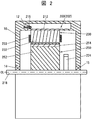
- FIG. 2 is a partial cross-sectional schematic view schematically showing a state where the rotating electrical machine 200 according to the present embodiment is attached to a vehicle.
- the rotating electrical machine 200 is disposed inside the case 10 on the vehicle side, and is rotatably disposed with a gap between the stator 230 and the inner peripheral side of the stator 230. And a rotor 250.
- the case 10 is provided integrally with an engine case or a transmission case.
- the stator 230 has a cylindrical housing (shrink fit ring) 212 and a stator core 232 fixed in the housing 212.
- the stator 230 is fixed in the case 10 by a flange 215 provided in the housing 212 being fastened to the case 10 by bolts 12.
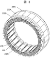
- FIG. 3 is a perspective view showing the stator 230 of the rotating electrical machine according to the present embodiment.
- the housing 212 for fixing the stator 230 is not shown.
- the stator core 232 of the stator 230 of the rotating electrical machine according to the present embodiment is configured to be divided into two or more regions in the rotation axis direction.
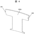
- the stator core 232 includes a first stator core 232A (hereinafter referred to as a T-shaped core) in which a tooth portion for one slot and a core back portion are integrated, and a second stator core 232B that includes only a tooth portion for one slot. (Hereinafter referred to as an I-shaped core) and a third stator core 232C (hereinafter referred to as an annular core back) composed only of core back portions connected in the circumferential direction.
- the T-shaped core 232A has a shape in which a tooth portion for one slot and a core back portion are integrated.
- a circumferential convex fitting portion 241 and a circumferential concave fitting portion 242 are provided at a circumferential division position (circumferential end portion) of the core back portion. These fitting portions are used for positioning with adjacent T-shaped cores.
- the I-shaped core 232B is composed of teeth 238 for one slot.
- a radially convex fitting portion 243 is provided on the outer peripheral side of the I-shaped core 232B.
- the radial convex fitting portion 243 is used for positioning with the annular core back 232C shown in FIG.
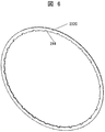
- the annular core back 232 ⁇ / b> C has a shape in which the core back portion is integrated in the circumferential direction.
- a radial concave fitting portion 244 is provided on the inner diameter side of the annular core back 232C.
- the radial concave fitting portion 244 is used for fitting with the radial convex fitting portion 243 of the I-shaped core 232B.
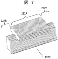
- FIG. 7 is a perspective view when the T-shaped core 232A and the I-shaped core 232B are laminated so that the tooth portions of both overlap each other.
- Each of the T-shaped core 232A and the I-shaped core 232B is configured by laminating thin plates having a thickness of about 0.2 mm.
- I-shaped cores 232B are arranged on both ends in the stacking direction.
- the core stacked in the form of FIG. 7 is referred to as a split core 232D.
- FIG. 8 shows a stator core 233 wound around a tooth 238 via an insulating bobbin 270 around a split core 232D.
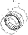
- FIG. 9 shows an annular core back 232C in which the split core 232D around which the stator coil 233 is wound as shown in FIG. 8 is stacked so as to have the same thickness as the I-shaped core 232B of the split core 232D (for example, the same number). It is a disassembled perspective view when combining with.
- the radial convex fitting portion 243 of the I-shaped core 232B of the split core 232D is positioned by fitting with the radial concave fitting portion 244 of the annular core back 232C. That is, the annular core back 232C is arranged at both axial ends of the split core 232D.
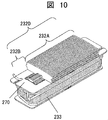
- FIG. 10 shows a split core 232D according to the second embodiment of the present invention.
- the I-shaped core 232B is disposed only on one end face in the rotation axis direction
- the T-shaped core 232A is disposed on the other end face.
- the annular core back 232C has a structure arranged only on one end face in the rotation axis direction where the I-shaped core 232B is arranged.
- the other end surface on which the T-shaped core 232A is arranged is provided with an annular rib 213 on the inner diameter side of the housing 212, and the divided surface of the T-shaped core 232A is pressed in the direction of the rotation axis.
- the step of combining the annular core back 232C and the split core 232D is halved, and the T-shaped core 232A at the time of shrink fitting is halved as in the first embodiment. Deformation can be reduced.
- deformation at the contact portion between adjacent divided cores can be reduced during shrink fitting.
- this invention is not limited to the above-mentioned Example, Various modifications are included.
- the above-described embodiments have been described in detail for easy understanding of the present invention, and are not necessarily limited to those having all the configurations described.
- a part of the configuration of one embodiment can be replaced with the configuration of another embodiment, and the configuration of another embodiment can be added to the configuration of one embodiment.
Landscapes
- Engineering & Computer Science (AREA)
- Power Engineering (AREA)
- Transportation (AREA)
- Mechanical Engineering (AREA)
- Manufacturing & Machinery (AREA)
- Iron Core Of Rotating Electric Machines (AREA)
- Manufacture Of Motors, Generators (AREA)
Abstract
焼き嵌めの際、隣接する分割コア同士の接触部における変形を低減する。 第1のステータコア232Aと第2のステータコア232B,232Cとにより構成されたステータコア232を備える回転電機において、第1のステータコア232Aは周方向に分割されたコアバックを有し、第2のステータコア232B,232Cは周方向に一体に構成されたコアバックを有し、第1のステータコア232Aと、第2のステータコア232B,232Cとが軸方向に積層されている回転電機のステータ。
Description
本発明は、回転電機のステータに関する。
回転電機は、ロータとステータとを備えており、ステータにはステータコイルが巻き回されている。回転電機をモータとして動作させて機械的動力を得る場合は、ステータコイルに電流を流してロータに回転力を付与する。回転電機により発電して電力を得る場合には、ロータを外部からの回転力により回転させ、ステータコイルに発生する電流を取り出す。
回転電機を動作させる際には、ステータコイルに電流を流すことにより生じる銅損や、ステータコアに渦電流が流れることにより生じる鉄損などの損失が生じるため、これらの損失を低減することが重要である。
一般に、鉄損を低減する技術のひとつとして、ステータコアを互いに電気的に絶縁した薄板状の電磁鋼板を積層することがある。この場合、帯状の電磁鋼板をステータコアの形状である円環状に打ち抜き、打ち抜いた円環状の鋼板を複数枚積層することでステータコアを形成するが、ステータコアの形状に打ち抜いたあとの残りの電磁鋼板が無駄になるため、歩留まり性が悪い。
そこで、ステータコア製造の歩留まり性を向上するために、ステータコアを複数の分割コアで形成することが知られている(特許文献1参照)。特許文献1には、材料歩留まり性を向上させるためのDCモータ用ステータコアの打ち抜き配置方法が記載されている。このような分割コアを用いた回転電機は材料コストの面で有利であり、広く採用されている。
分割コアで形成されるステータコアは、ハウジングにより固定される。ステータコアとハウジングとを固定する方法のひとつとして、焼き嵌めが広く適用されている。焼き嵌めは、ハウジングをあらかじめ高温に熱し、その熱膨張によりハウジングの内径を拡大した状態でステータコアに嵌め込み、そのまま冷却することで、ステータコアをハウジングにより締め付けて固定する方法である。
常温におけるステータコアの外径寸法とハウジングの内径寸法との差である締め代は、運転時におけるロータのトルクによる反作用によってステータコアがハウジングに対して空転しないように設定されている。
締め代を大きく設定しておき、ハウジングによる締め付け力を大きくすることで、複数の分割コアから構成されるステータコアを安定して固定することができる。しかし、前述の通り分割コアは薄板状の電磁鋼板を積層することで形成されており、電磁鋼板の一枚の強度は高くない。よって、締め付け力を大きくすると、隣接する分割コア同士が押し合うことで隣接する分割コア同士の接触部が変形し、回転軸方向に突き出てしまうことがあった。
上記課題を解決するために、例えば請求の範囲に記載の構成を採用する。
本願は上記課題を解決する手段を複数含んでいるが、その一例を挙げるならば、第1のステータコアと第2のステータコアとにより構成されたステータコアを備える回転電機のステータにおいて、前記第1のステータコアは周方向に分割されたコアバックを有し、前記第2のステータコアは周方向に一体に構成されたコアバックを有し、前記第1のステータコアと、前記第2のステータコアとが軸方向に積層されていることを特徴とする。
本願は上記課題を解決する手段を複数含んでいるが、その一例を挙げるならば、第1のステータコアと第2のステータコアとにより構成されたステータコアを備える回転電機のステータにおいて、前記第1のステータコアは周方向に分割されたコアバックを有し、前記第2のステータコアは周方向に一体に構成されたコアバックを有し、前記第1のステータコアと、前記第2のステータコアとが軸方向に積層されていることを特徴とする。
本発明によれば、焼き嵌めの際、隣接する分割コア同士の接触部における変形を低減する回転電機を提供することができる。
上記した以外の課題、構成及び効果は、以下の実施形態の説明により明らかにされる。
上記した以外の課題、構成及び効果は、以下の実施形態の説明により明らかにされる。
本発明による回転電機の実施形態を、図面を用いて説明する。
なお、以下の説明では、回転電機の一例として電気自動車やハイブリッド自動車の走行用の回転電機を用いる。また、以下の説明において、「軸方向」は回転電機の回転軸に沿った方向を指す。周方向は回転電機の回転方向に沿った方向を指す。「径方向」は回転電機の回転軸を中心としたときの動径方向(半径方向)を指す。「内周側」は径方向内側(内径側)を指し、「外周側」はその逆方向、すなわち径方向外側(外径側)を指す。
〔第1の実施形態〕
図1は、本実施形態に係る回転電機を搭載したハイブリッド型電気自動車の概略構成を示す図である。
なお、以下の説明では、回転電機の一例として電気自動車やハイブリッド自動車の走行用の回転電機を用いる。また、以下の説明において、「軸方向」は回転電機の回転軸に沿った方向を指す。周方向は回転電機の回転方向に沿った方向を指す。「径方向」は回転電機の回転軸を中心としたときの動径方向(半径方向)を指す。「内周側」は径方向内側(内径側)を指し、「外周側」はその逆方向、すなわち径方向外側(外径側)を指す。
〔第1の実施形態〕
図1は、本実施形態に係る回転電機を搭載したハイブリッド型電気自動車の概略構成を示す図である。
図1に示すように、ハイブリッド自動車(以下、車両)100には、エンジン120と、第1の回転電機200と、第2の回転電機202と、バッテリ180とが搭載されている。
バッテリ180は、リチウムイオン電池あるいはニッケル水素電池などの二次電池やキャパシタで構成され、250ボルトから600ボルト、あるいはそれ以上の高電圧の直流電力を出力する。バッテリ180は、力行走行時には回転電機200,202に直流電力を供給し、回生走行時には回転電機200,202から直流電力を受ける。バッテリ180と回転電機200,202との間の直流電力の授受は、電力変換装置600を介して行われる。
車両100には低電圧電力(たとえば、14ボルト系電力)を供給するバッテリ(図示せず)が搭載されており、以下に説明する制御回路に直流電力を供給する。
エンジン120および回転電機200,202による回転トルクは、変速機130とデファレンシャルギア160を介して前輪110に伝達される。変速機130は変速機制御装置134により制御され、エンジン120はエンジン制御装置124により制御され、バッテリ180は、バッテリ制御装置184により制御される。
変速機制御装置134、エンジン制御装置124、バッテリ制御装置184および電力変換装置600には、通信回線174を介して統合制御装置170が接続されている。
統合制御装置170は、変速機制御装置134、エンジン制御装置124、電力変換装置600およびバッテリ制御装置184の状態を表す情報を、通信回線174を介してそれらからそれぞれ受け取る。統合制御装置170は、取得したそれらの情報に基づき各制御装置の制御指令を演算する。演算された制御指令は通信回線174を介してそれぞれの制御装置へ送信される。
バッテリ制御装置184は、バッテリ180の充放電状況やバッテリ180を構成する各単位セル電池の状態を、通信回線174を介して統合制御装置170に出力する。
統合制御装置170は、バッテリ制御装置184からの情報に基づいてバッテリ180の充電が必要と判断すると、電力変換装置600に発電運転の指示を出す。
統合制御装置170は、エンジン120および回転電機200,202の出力トルクの管理、エンジン120の出力トルクと回転電機200,202の出力トルクとの総合トルクやトルク分配比の演算処理を行い、その演算処理結果に基づく制御指令を、変速機制御装置134、エンジン制御装置124および電力変換装置600へ送信する。
電力変換装置600は、統合制御装置170からのトルク指令に基づき、指令通りのトルク出力あるいは発電電力が発生するように回転電機200,202を制御する。電力変換装置600にはインバータを構成するパワー半導体素子が設けられている。電力変換装置600は、統合制御装置170からの指令に基づきパワー半導体素子のスイッチング動作を制御する。パワー半導体素子のスイッチング動作により、回転電機200,202は電動機としてあるいは発電機として運転される。
回転電機200,202を電動機として運転する場合は、高電圧のバッテリ180からの直流電力が電力変換装置600のインバータの直流端子に供給される。電力変換装置600は、パワー半導体素子のスイッチング動作を制御して供給された直流電力を3相交流電力に変換し、回転電機200,202に供給する。
一方、回転電機200,202を発電機として運転する場合には、ロータが外部から加えられる回転トルクで回転駆動され、ステータコイルに3相交流電力が発生する。発生した3相交流電力は電力変換装置600で直流電力に変換され、その直流電力が高電圧のバッテリ180に供給されることにより、バッテリ180が充電される。
回転電機200,202の構造について説明する。第1の回転電機200と第2の回転電機202とはほぼ同様の構造であるため、以下では、第1の回転電機200の構造を代表例として説明する。なお、以下に示す構造は回転電機200,202の双方に採用されている必要はなく、一方だけに採用されていてもよい。
図2は本実施形態に係る回転電機200を車両に取り付けた状態を模式的に示す一部断面模式図である。図2に示すように、回転電機200は、車両側のケース10の内部に配設されるものであり、ステータ230と、ステータ230の内周側に隙間をあけて回転可能に配設されたロータ250とを備えている。ケース10は、エンジンのケースや変速機のケースと一体的に設けられている。
ステータ230は、円筒状のハウジング(焼き嵌めリング)212と、ハウジング212内に固定されたステータコア232とを有している。ステータ230は、ハウジング212に設けられたフランジ215がボルト12によりケース10に締結されることで、ケース10内に固定されている。
図3は、本実施形態に係る回転電機のステータ230を示す斜視図である。なお、図3では、ステータ230を固定するためのハウジング212は図示していない。
図3に示すように、本実施形態に係る回転電機のステータ230のステータコア232は、回転軸方向に2つ以上の領域に分かれて構成している。
図4~図6は、本実施形態に係る回転電機のステータコア232の形状を示したものである。ステータコア232は、1スロット分のティース部分とコアバック部分が一体となった第1のステータコア232A(以下、T字形コアと記載する)と、1スロット分のティース部分のみからなる第2のステータコア232B(以下、I字形コアと記載する)と、円周方向に連結したコアバック部分のみからなる第3のステータコア232C(以下、環状コアバックと記載する)とを組み合わせることで構成する。
図4に示すように、T字形コア232Aは、1スロット分のティース部分とコアバック部分とが一体となった形状である。コアバック部分の周方向分割位置(周方向端部)には周方向凸嵌合部241および周方向凹嵌合部242が設けられている。これらの嵌合部は隣接するT字形コアとの位置決めに用いられる。
図5に示すように、I字形コア232Bは、1スロット分のティース238から構成されている。I字形コア232Bの外周側には径方向凸嵌合部243が設けられている。径方向凸嵌合部243は図6に示す環状コアバック232Cとの位置決めに用いられる。
図6に示すように、環状コアバック232Cは、コアバック部分が円周方向に一体となった形状である。環状コアバック232Cの内径側には径方向凹嵌合部244が設けられている。径方向凹嵌合部244はI字形コア232Bの径方向凸嵌合部243との嵌合に用いられる。
図7は、T字形コア232AとI字形コア232Bとを、両者のティース部が重なるように積層したときの斜視図である。T字形コア232AとI字形コア232Bは、いずれも厚さが0.2mm程度の薄板を積層することで構成される。図7に示すように積層方向の両端側にI字形コア232Bを配置するようにする。以下、図7の形態に積層したコアを分割コア232Dと記載する。
図8は、分割コア232Dに絶縁ボビン270を介してステータコイル233をティース238に巻きまわしたものである。
図9は、図8のようにしてステータコイル233を巻きまわした分割コア232Dを、分割コア232DのI字形コア232Bと同じ厚さになるように(例えば同じ枚数で)積層した環状コアバック232Cと組み合わせたときの分解斜視図である。分割コア232DのI字形コア232Bの径方向凸嵌合部243を、環状コアバック232Cの径方向凹嵌合部244に嵌合することで位置決めする構成となっている。すなわち、環状コアバック232Cが分割コア232Dの軸方向両端に配置される構成である。
以上のような構成により本実施形態では、ステータコア232の回転軸方向の端面に、分割コア232Dの周方向分割面が露出せず、ステータコア232の回転軸方向の端面には、環状コアバック232Cが露出していることになる。本構造により、ハウジング212をステータコア232に焼き嵌めで固定したときに、圧縮応力により分割コア232Dの分割面が回転軸方向に突き出る変形を低減することができる。
〔第2の実施形態〕
図10に本発明の第2の実施形態の分割コア232Dを示す。本形態では、I字形コア232Bを回転軸方向の一方の端面にのみ配置し、他方の端面はT字形コア232Aが配置される構成となっている。
〔第2の実施形態〕
図10に本発明の第2の実施形態の分割コア232Dを示す。本形態では、I字形コア232Bを回転軸方向の一方の端面にのみ配置し、他方の端面はT字形コア232Aが配置される構成となっている。
この場合、図11に示すように、環状コアバック232CはI字形コア232Bを配置した回転軸方向の一方の端面にのみ配置する構造となるため。T字形コア232Aが配置されている他方の端面は、ハウジング212の内径側に円環状のリブ213を設け、T字形コア232Aの分割面を回転軸方向に押し付ける構造とし、環状コアバック232と同様の効果を持たせて、焼き嵌め時のT字形コア232Aの周方向分割面の変形を低減する。
本実施形態によれば、第1の実施形態と比較して、環状コアバック232Cと分割コア232Dを組み合わせる工程を半分にして、第1の実施形態と同様に焼き嵌め時のT字形コア232Aの変形を低減することができる。
以上で説明したように、本発明によれば、焼き嵌めの際、隣接する分割コア同士の接触部における変形を低減することができる。
なお、本発明は上記した実施例に限定されるものではなく、様々な変形例が含まれる。例えば、上記した実施例は本発明を分かりやすく説明するために詳細に説明したものであり、必ずしも説明した全ての構成を備えるものに限定されるものではない。また、ある実施例の構成の一部を他の実施例の構成に置き換えることが可能であり、また、ある実施例の構成に他の実施例の構成を加えることも可能である。また、各実施例の構成の一部について、他の構成の追加・削除・置換をすることが可能である。
10 ケース
12 ボルト
200 回転電機
202 回転電機
212 ハウジング
213 リブ
215 フランジ
230 ステータ
232 ステータコア
232A 第1のステータコア(T字形コア)
232B 第2のステータコア(I字形コア)
232C 第3のステータコア(環状コアバック)
232D 分割コア
233 ステータコイル
238 ティース
250 ロータ
252 ロータコア
270 絶縁ボビン
12 ボルト
200 回転電機
202 回転電機
212 ハウジング
213 リブ
215 フランジ
230 ステータ
232 ステータコア
232A 第1のステータコア(T字形コア)
232B 第2のステータコア(I字形コア)
232C 第3のステータコア(環状コアバック)
232D 分割コア
233 ステータコイル
238 ティース
250 ロータ
252 ロータコア
270 絶縁ボビン
Claims (7)
- 第1のステータコアと第2のステータコアとにより構成されたステータコアを備える回転電機のステータにおいて、
前記第1のステータコアは周方向に分割されたコアバックを有し、
前記第2のステータコアは周方向に一体に構成されたコアバックを有し、
前記第1のステータコアと、前記第2のステータコアとが軸方向に積層されている回転電機のステータ。 - 請求項1に記載の回転電機のステータにおいて、
前記第1のステータコアが、1スロット毎に周方向に分割されたT字形コアからなり、
前記第2のステータコアが、環状コアバックと、当該環状コアバックに配置されるI字形コアとからなり、
前記I字形コアと前記T字形コアのティース部分とが前記軸方向に積層され、1つのティースを構成している回転電機のステータ。 - 請求項2に記載の回転電機のステータにおいて、
前記第2のステータコアが、前記ステータコアの少なくとも一方の軸方向端部に配置されている回転電機のステータ。 - 請求項3に記載の回転電機のステータにおいて、
前記第2のステータコアが、前記ステータコアの両方の軸方向端部に配置されている回転電機のステータ。 - 請求項3に記載の回転電機のステータにおいて、
前記ステータコアを保持するハウジングを備え、
前記ハウジングは内周面にリブを有し、
前記第2のステータコアが、前記ステータコアの一方の軸方向端部に配置され、
前記第1のステータコアが、前記ステータコアの他方の軸方向端部に配置され、
前記リブが、前記ステータコアの前記他方の軸方向端部において、前記第1のステータコアのコアバックと接している回転電機のステータ。 - 請求項3に記載の回転電機のステータにおいて、
前記第2のステータコアが積層された薄板により構成され、
前記環状コアバックを構成する薄板の枚数と、前記I字型コアを構成する薄板の枚数とが同じである回転電機のステータ。 - 請求項1乃至6のいずれか一項に記載の回転電機のステータと、
前記ステータの内周側に回転可能に配置されたロータとを備える回転電機。
Priority Applications (1)
| Application Number | Priority Date | Filing Date | Title |
|---|---|---|---|
| JP2015516971A JP6111329B2 (ja) | 2013-05-16 | 2014-03-10 | 回転電機のステータ |
Applications Claiming Priority (2)
| Application Number | Priority Date | Filing Date | Title |
|---|---|---|---|
| JP2013-103625 | 2013-05-16 | ||
| JP2013103625 | 2013-05-16 |
Publications (1)
| Publication Number | Publication Date |
|---|---|
| WO2014185134A1 true WO2014185134A1 (ja) | 2014-11-20 |
Family
ID=51898120
Family Applications (1)
| Application Number | Title | Priority Date | Filing Date |
|---|---|---|---|
| PCT/JP2014/056096 Ceased WO2014185134A1 (ja) | 2013-05-16 | 2014-03-10 | 回転電機のステータ |
Country Status (2)
| Country | Link |
|---|---|
| JP (1) | JP6111329B2 (ja) |
| WO (1) | WO2014185134A1 (ja) |
Cited By (3)
| Publication number | Priority date | Publication date | Assignee | Title |
|---|---|---|---|---|
| GB2579358A (en) * | 2018-11-28 | 2020-06-24 | Jaguar Land Rover Ltd | A stator and a stator housing for an electric machine |
| GB2579357A (en) * | 2018-11-28 | 2020-06-24 | Jaguar Land Rover Ltd | A stator and stator housing |
| CN114379352A (zh) * | 2020-10-22 | 2022-04-22 | 马自达汽车株式会社 | 车辆 |
Citations (3)
| Publication number | Priority date | Publication date | Assignee | Title |
|---|---|---|---|---|
| JPH11289696A (ja) * | 1998-03-31 | 1999-10-19 | Nissan Motor Co Ltd | ステータおよびその製造方法 |
| JP2002315251A (ja) * | 2001-04-12 | 2002-10-25 | Okuma Corp | 電動機の固定子およびその製造方法 |
| JP2012143064A (ja) * | 2010-12-28 | 2012-07-26 | Denso Corp | 回転電機の固定子及びその製造方法 |
-
2014
- 2014-03-10 JP JP2015516971A patent/JP6111329B2/ja active Active
- 2014-03-10 WO PCT/JP2014/056096 patent/WO2014185134A1/ja not_active Ceased
Patent Citations (3)
| Publication number | Priority date | Publication date | Assignee | Title |
|---|---|---|---|---|
| JPH11289696A (ja) * | 1998-03-31 | 1999-10-19 | Nissan Motor Co Ltd | ステータおよびその製造方法 |
| JP2002315251A (ja) * | 2001-04-12 | 2002-10-25 | Okuma Corp | 電動機の固定子およびその製造方法 |
| JP2012143064A (ja) * | 2010-12-28 | 2012-07-26 | Denso Corp | 回転電機の固定子及びその製造方法 |
Cited By (7)
| Publication number | Priority date | Publication date | Assignee | Title |
|---|---|---|---|---|
| GB2579358A (en) * | 2018-11-28 | 2020-06-24 | Jaguar Land Rover Ltd | A stator and a stator housing for an electric machine |
| GB2579357A (en) * | 2018-11-28 | 2020-06-24 | Jaguar Land Rover Ltd | A stator and stator housing |
| GB2579358B (en) * | 2018-11-28 | 2021-06-09 | Jaguar Land Rover Ltd | A stator and a stator housing for an electric machine |
| GB2579357B (en) * | 2018-11-28 | 2021-10-06 | Jaguar Land Rover Ltd | A stator and stator housing |
| US12388304B2 (en) | 2018-11-28 | 2025-08-12 | Jaguar Land Rover Limited | Stator and a stator housing for an electric machine |
| CN114379352A (zh) * | 2020-10-22 | 2022-04-22 | 马自达汽车株式会社 | 车辆 |
| CN114379352B (zh) * | 2020-10-22 | 2023-06-02 | 马自达汽车株式会社 | 车辆 |
Also Published As
| Publication number | Publication date |
|---|---|
| JP6111329B2 (ja) | 2017-04-05 |
| JPWO2014185134A1 (ja) | 2017-02-23 |
Similar Documents
| Publication | Publication Date | Title |
|---|---|---|
| US11362552B2 (en) | Electric machine component and method to fabricate | |
| EP3079234B1 (en) | Rotary electric machine | |
| CN103201931B (zh) | 旋转电机 | |
| JP5789538B2 (ja) | 回転電機および回転電機の製造方法 | |
| JP5681026B2 (ja) | 固定子および回転電機 | |
| US20110018384A1 (en) | Motor | |
| US20170256997A1 (en) | Stator of Rotary Electric Machine and Rotary Electric Machine Equipped with the Same | |
| JP5632308B2 (ja) | かご形回転子および回転電機 | |
| CN102593980A (zh) | 旋转电机转子 | |
| US20090218906A1 (en) | Rotating electric machine and method of manufacturing the same | |
| US20140167556A1 (en) | Electric rotating machine | |
| JP6111329B2 (ja) | 回転電機のステータ | |
| JP4649973B2 (ja) | アキシャルギャップ型回転電機のコイル結線構造 | |
| CN102742124B (zh) | 定子以及旋转电机 | |
| JP5386265B2 (ja) | 回転電機および車両 | |
| JP7030961B2 (ja) | 固定子、及び回転電機 | |
| US20210384779A1 (en) | Rotary Electric Machine and Vehicle | |
| WO2022254801A1 (ja) | 回転電機及び電動駆動システム | |
| JP6416655B2 (ja) | 回転電機の固定子 | |
| JP5988840B2 (ja) | 回転電機の固定子 | |
| JP2003164125A (ja) | 両面空隙型回転電機 | |
| JP7638840B2 (ja) | 回転電機の回転子 | |
| JP5547137B2 (ja) | 回転電機 | |
| JP2011125180A (ja) | ステータ | |
| CN118117791A (zh) | 转子冲片、转子铁芯、电机和工业设备 |
Legal Events
| Date | Code | Title | Description |
|---|---|---|---|
| 121 | Ep: the epo has been informed by wipo that ep was designated in this application |
Ref document number: 14798483 Country of ref document: EP Kind code of ref document: A1 |
|
| ENP | Entry into the national phase |
Ref document number: 2015516971 Country of ref document: JP Kind code of ref document: A |
|
| NENP | Non-entry into the national phase |
Ref country code: DE |
|
| 122 | Ep: pct application non-entry in european phase |
Ref document number: 14798483 Country of ref document: EP Kind code of ref document: A1 |