WO2014181704A1 - 伝達機構及びこの伝達機構を用いたアクチュエータ - Google Patents
伝達機構及びこの伝達機構を用いたアクチュエータ Download PDFInfo
- Publication number
- WO2014181704A1 WO2014181704A1 PCT/JP2014/061671 JP2014061671W WO2014181704A1 WO 2014181704 A1 WO2014181704 A1 WO 2014181704A1 JP 2014061671 W JP2014061671 W JP 2014061671W WO 2014181704 A1 WO2014181704 A1 WO 2014181704A1
- Authority
- WO
- WIPO (PCT)
- Prior art keywords
- rotating member
- transmission mechanism
- shaft
- output shaft
- actuator
- Prior art date
- Legal status (The legal status is an assumption and is not a legal conclusion. Google has not performed a legal analysis and makes no representation as to the accuracy of the status listed.)
- Ceased
Links
Images



Classifications
-
- F—MECHANICAL ENGINEERING; LIGHTING; HEATING; WEAPONS; BLASTING
- F16—ENGINEERING ELEMENTS AND UNITS; GENERAL MEASURES FOR PRODUCING AND MAINTAINING EFFECTIVE FUNCTIONING OF MACHINES OR INSTALLATIONS; THERMAL INSULATION IN GENERAL
- F16H—GEARING
- F16H25/00—Gearings comprising primarily only cams, cam-followers and screw-and-nut mechanisms
- F16H25/18—Gearings comprising primarily only cams, cam-followers and screw-and-nut mechanisms for conveying or interconverting oscillating or reciprocating motions
- F16H25/20—Screw mechanisms
- F16H25/22—Screw mechanisms with balls, rollers, or similar members between the co-operating parts; Elements essential to the use of such members
- F16H25/2204—Screw mechanisms with balls, rollers, or similar members between the co-operating parts; Elements essential to the use of such members with balls
- F16H25/2214—Screw mechanisms with balls, rollers, or similar members between the co-operating parts; Elements essential to the use of such members with balls with elements for guiding the circulating balls
-
- F—MECHANICAL ENGINEERING; LIGHTING; HEATING; WEAPONS; BLASTING
- F16—ENGINEERING ELEMENTS AND UNITS; GENERAL MEASURES FOR PRODUCING AND MAINTAINING EFFECTIVE FUNCTIONING OF MACHINES OR INSTALLATIONS; THERMAL INSULATION IN GENERAL
- F16D—COUPLINGS FOR TRANSMITTING ROTATION; CLUTCHES; BRAKES
- F16D23/00—Details of mechanically-actuated clutches not specific for one distinct type
- F16D23/12—Mechanical clutch-actuating mechanisms arranged outside the clutch as such
- F16D2023/123—Clutch actuation by cams, ramps or ball-screw mechanisms
-
- F—MECHANICAL ENGINEERING; LIGHTING; HEATING; WEAPONS; BLASTING
- F16—ENGINEERING ELEMENTS AND UNITS; GENERAL MEASURES FOR PRODUCING AND MAINTAINING EFFECTIVE FUNCTIONING OF MACHINES OR INSTALLATIONS; THERMAL INSULATION IN GENERAL
- F16D—COUPLINGS FOR TRANSMITTING ROTATION; CLUTCHES; BRAKES
- F16D28/00—Electrically-actuated clutches
-
- F—MECHANICAL ENGINEERING; LIGHTING; HEATING; WEAPONS; BLASTING
- F16—ENGINEERING ELEMENTS AND UNITS; GENERAL MEASURES FOR PRODUCING AND MAINTAINING EFFECTIVE FUNCTIONING OF MACHINES OR INSTALLATIONS; THERMAL INSULATION IN GENERAL
- F16H—GEARING
- F16H25/00—Gearings comprising primarily only cams, cam-followers and screw-and-nut mechanisms
- F16H25/18—Gearings comprising primarily only cams, cam-followers and screw-and-nut mechanisms for conveying or interconverting oscillating or reciprocating motions
- F16H25/20—Screw mechanisms
- F16H2025/2062—Arrangements for driving the actuator
- F16H2025/2081—Parallel arrangement of drive motor to screw axis
Definitions
- the present invention relates to a transmission mechanism for transmitting a driving force input from an input shaft to an output shaft, and an actuator using the transmission mechanism, and in particular, even when the input shaft becomes non-rotatable due to locking or the like.
- the present invention relates to a transmission mechanism having a fail-safe function capable of applying a driving force to an output shaft, and an actuator using the transmission mechanism.
- a rotation operation shaft is rotated by a lever member attached to a housing, and the rotation operation shaft The slide member is advanced and retracted by rotation to switch between manual operation and electric operation.
- the lever member protrudes greatly from the housing, and there is a problem that the size of the entire actuator is increased and the operation becomes large. Further, since the rotation operation shaft is configured to be rotatable, the number of parts of the transmission mechanism is increased, and the housing itself is also increased in size.
- the present invention has been made in order to solve the above-described problems, and suppresses an increase in the number of parts, and does not increase the size of the entire apparatus, and can perform a switching operation with a simple operation. And it aims at providing the actuator provided with this transmission mechanism.
- a transmission mechanism is a transmission mechanism that transmits a driving force from an input shaft to an output shaft, the first rotating member to which the driving force is applied from the input shaft side, and a driving force applied to the output shaft.
- a second rotating member that provides rotation, a penetrating shaft that rotates together with the first rotating member and penetrates the second rotating member so as to be concentrically disposed with the first rotating member, and the second rotation
- a first restraining portion that is disposed on the first rotating member side of the member and rotates together with the second rotating member, and rotates together with the through shaft and is detachably disposed with respect to the first restraining portion.
- a second restraining portion is provided, wherein the through shaft protrudes from one end of the second rotating member.
- the first rotating member to which the driving force is applied from the input shaft side, the second rotating member to apply the driving force to the output shaft, the first rotating member, and the second rotating member rotate together with the second rotating member.
- a second restraining portion that rotates together with the through shaft and is detachably disposed with the first restraining portion, and the through shaft projects from one end of the second rotating member.
- the release of the restraint of the second restraining part can be performed by pushing the penetrating shaft protruding from the second rotating member, so that it is possible to switch between manual operation and electric operation with a simple configuration and simple operation. .
- Sectional drawing for demonstrating the structure of the actuator using the transmission mechanism which concerns on embodiment of this invention The partial cross section figure for demonstrating the structure of the ball screw apparatus used for the actuator which concerns on embodiment of this invention.
- FIG. 1 is a cross-sectional view for explaining the structure of an actuator using a transmission mechanism according to an embodiment of the present invention
- FIG. 2 shows the structure of a ball screw device used for the actuator according to the embodiment of the present invention
- FIG. 3 is a partial cross-sectional view for explaining
- FIG. 3 is a front view of a first rotating member used in the transmission mechanism according to the embodiment of the present invention
- FIG. 4 is a transmission according to the embodiment of the present invention.
- FIG. 5 is a side view of a second rotating member used in the mechanism
- FIG. 5 is a side view of a penetrating shaft used in the transmission mechanism according to the embodiment of the present invention
- FIGS. 6 and 7 illustrate the implementation of the present invention. It is a perspective view for demonstrating the structure of the transmission mechanism which concerns on a form.
- the actuator 1 using the transmission mechanism 30 has a drive source 12 having an input shaft 10 and an output shaft 20, and the input shaft 10, the output shaft 20, A transmission mechanism 30 is interposed between them. These components are housed in a housing 2 to constitute the actuator 1.
- the drive source 12 can use various element parts such as an electric motor, and applies a rotational force for performing a rotational motion to the input shaft 10.
- An input gear 11 is attached to the input shaft 10, and the rotational force is transmitted to the transmission mechanism 30 by the input gear 11.
- the output shaft 20 is rotatably held by a bearing 22, and a rotational force is applied from the transmission mechanism 30 by an output gear 21 attached to the output shaft 20.
- the output shaft 20 constitutes the ball screw device 3, and this rotational motion is converted into a linear motion of the nut 23 by rotating the output shaft 20 with a rotational force applied via the transmission mechanism 30.
- the ball screw device 3 is housed in an outer cylinder 25 attached to the housing 2, and an expansion / contraction part 24 is disposed to be extendable from one end of the outer cylinder 25.
- a parallel key 26 is attached to the nut 23, and the parallel key 26 engages with a key groove 27 formed along the longitudinal direction on the inner periphery of the outer cylinder 25 to rotate the nut 23. It is regulated.
- the expansion / contraction part 24 is a cylindrical member, and one end is attached to the nut 23 so that it moves along with the movement of the nut 23 and can accommodate the output shaft 20 on the inner peripheral side.
- the expansion / contraction part 24 is formed in a cylindrical shape, the output shaft 20 and the expansion / contraction part 24 do not interfere with each other even when the expansion / contraction part 24 is housed in the outer cylinder 25. Can be formed compactly.
- the ball screw device 3 used in the actuator 1 has an output configured as a screw shaft in which a spiral rolling element rolling groove 20 a is formed on the outer peripheral surface with a predetermined lead.
- the shaft 20 and a nut hole 23c through which the output shaft 20 penetrates are formed in a cylindrical shape, and the load rolling that faces the rolling element rolling groove 20a formed in the output shaft 20 on the inner peripheral surface of the nut hole 23c.
- a plurality of balls 29 are arranged between the rolling element rolling groove 20a and the loaded rolling element rolling groove 23a, and the output shaft 20 and the nut 23 are screwed together.
- the nut 23 is not limited to a cylindrical shape, and for example, a cross-sectional shape orthogonal to the axial direction may be formed in a cylindrical shape such as an external rectangular shape.
- the ball screw device 3 configured as described above is configured such that the nut 23 moves along the axial direction of the output shaft 20 by the relative rotation of the output shaft 20 and the nut 23.
- the nut 23 is formed of a metal such as steel in a cylindrical shape, and a flange 23b for fixing the nut 23 to a counterpart part is formed on the outer peripheral surface thereof so as to extend in the radial direction of the nut 23.
- Seal members 28 are attached to both ends of the nut hole 23c in the axial direction. The seal member 28 prevents dust and the like from entering between the output shaft 20 and the nut 23 and It is possible to prevent the applied lubricant from leaking out of the ball screw device 3.
- the nut 23 has a return pipe formed on the inner periphery thereof with a direction changing path that changes the traveling direction of the ball 29 that has rolled in the rolling element rolling groove 20a to return to the original position of the rolling element rolling groove 20a. 29a is attached.
- this return pipe 29a the ball 29 that has rolled the rolling element rolling groove 20a in the circumferential direction of the output shaft 20 is returned to the original position, thereby realizing infinite circulation of the ball 29.
- the return pipe 29 a is inserted and fixed in an attachment hole drilled along the radial direction of the nut 23.
- the transmission mechanism 30 includes a first rotating member 31 and a second rotating member 32, and the first rotating member 31 and the second rotating member 32 are arranged so as to be concentrically arranged.
- the through shaft 33 that penetrates the member 31 and the second rotating member 32 is combined.
- both the first rotating member 31 and the second rotating member 32 are gears.
- the first rotating member 31 has a first tooth portion 31 a formed on the outer periphery, and a center hole 34 a through which the above-described through shaft 33 passes is drilled at the center. Further, a groove 34 on the notch is formed in the center hole 34a.
- the second rotating member 32 has a second tooth portion 32 a formed on the outer periphery, an operation means attachment portion 37 extending in the axial direction at one end, and a first restraining portion on the other end surface. 35 is formed. Further, a through hole 36 is formed so as to penetrate the second tooth portion 32 a and the operation means attachment portion 37. A plurality of first restraining portions 35 are formed along the outer edge of the through hole 36 and are formed as claw portions protruding in the axial direction. Further, the outer periphery of the operation means attachment portion 37 is chamfered according to the tool so that a tool for manually rotating the second rotating member 32 can be attached.
- the through shaft 33 is a long cylindrical member, and a second restraining portion 38 that engages with the first restraining portion 35 described above is formed.
- the second restraining portion 38 is formed as a groove-like engaging portion that engages with the claw portion so as to correspond to the claw portion of the first restraining portion 35.
- a gear mounting portion 39 and an extension portion 40 extend in the axial direction at both ends of the second restraining portion 38 in the axial direction, and the gear mounting portion 39 is inserted into the center hole 34 a of the first rotating member 31. Then, the extension portion 40 is inserted into the through hole 36 of the second rotating member 32, so that the transmission mechanism 30 is integrally combined.
- the gear mounting portion 39 is formed with a key groove 39a along the axial direction, and a key 44 as a protrusion inserted into the key groove 39a is formed with a groove 34 formed on the first rotating member 31. By engaging, the penetrating shaft 33 and the first rotating member 31 can be rotated together.
- the first rotating member 31 is disposed so as to be movable in the axial direction along the through hole 36 of the second rotating member 32 together with the through shaft 33.
- the penetrating shaft 33 is biased toward the second rotating member 32 by the biasing means 41.
- Any member may be applied to the urging unit 41 as long as the penetrating shaft 33 can be urged toward the second rotating member 32.
- a coil spring is preferably used.
- the operation means mounting portion 37 of the second rotating member 32 protrudes outside the housing 2, and the extension portion 40 of the through shaft 33 protrudes from the end surface of the operation means mounting portion 37.
- the second rotating member 32 is attached to the housing 2 so as not to move in the axial direction by a C clip or the like.
- the operation of the transmission mechanism 30 according to the present embodiment will be described with reference to FIGS.
- the penetrating shaft 33 is biased toward the second rotating member 32 by the biasing means 41, so that the second shaft formed on the penetrating shaft 33 is used.
- the restraining portion 38 and the first restraining portion 35 formed on the second rotating member 32 are engaged with each other. In this state, since the first rotating member 31 and the second rotating member 32 rotate together, the rotational force of the input gear 11 is transmitted to the output gear 21 via the transmission mechanism 30.
- the second rotating member 32 can be rotated independently even if the input shaft 10 is unrotatable due to the failure of the drive source 12 or the fixing of the input shaft 10 due to the failure of the drive source 12.
- the rotation of the second rotating member 32 may be performed with bare hands, or may be rotated by attaching an operation means such as a predetermined tool to the operation means attachment portion 37. With this configuration, the output shaft 20 can be easily rotated with a small force, and the size of the actuator can be made compact by removing the operating means during electric operation.
- the actuator 1 using the transmission mechanism 30 urges the through shaft 33 by the urging member 41, the operation of pushing the extension 40 protruding from the second rotating member 32. Only manual operation and electric operation can be switched. With this configuration, the number of parts can be reduced, and the overall size of the transmission device 30 can be formed in a compact manner. Moreover, since it can switch to manual operation only by pushing the extension part 40, compared with the conventional switching operation, switching operation can be performed by very simple operation.
- the present invention is not limited to the above-described embodiment, and various modifications can be made without departing from the scope of the present invention.
- the first restraining portion and the second restraining portion are configured as the claw portion and the engaging portion
- the first restraining portion and the second restraining portion are described.
- the part is not limited to this, and for example, the first rotating member and the second rotating member may be integrally rotated using a friction plate.
- a speed reduction mechanism may be configured by meshing a plurality of gears.
- the first rotating member and the second rotating member are engaged with each other using gears.
- the shapes of the first rotating member and the second rotating member are described.
- the first rotating member and the second rotating member are constituted by a timing belt wheel, a sprocket, a pulley, and the like, and the input shaft, the first rotating member, the output shaft, and the second rotating member, It is also possible to construct a structure in which a timing belt, a chain and a belt are stretched to give a driving force.
- the ball screw device using the return pipe is described as the ball screw device.
- the ball screw device is not limited to this.
- an infinite circulation type ball screw device using a deflector is adopted.
- a finite circulation ball screw device or a sliding type that does not have rolling elements may be employed. It is apparent from the scope of the claims that the embodiments added with such changes or improvements can be included in the technical scope of the present invention.
Landscapes
- Engineering & Computer Science (AREA)
- General Engineering & Computer Science (AREA)
- Mechanical Engineering (AREA)
- Transmission Devices (AREA)
- Mechanical Operated Clutches (AREA)
Abstract
部品点数の増加を抑えると共に、装置全体が大型化することがなく、簡便な操作で切り替え操作を行うことができる伝達機構及び、この伝達機構を備えたアクチュエータを提供する。 入力軸からの駆動力を出力軸に伝達する伝達機構であって、前記入力軸側から駆動力を付与される第一の回転部材と、前記出力軸に駆動力を付与する第二の回転部材と、前記第一の回転部材と共に回転し、前記第二の回転部材を前記第一の回転部材と同心配置するように貫通する貫通軸と、前記第二の回転部材の前記第一の回転部材側に配されて前記第二の回転部材と共に回転する第一の拘束部と、前記貫通軸と共に回転し、前記第一の拘束部と係脱自在に配置された第二の拘束部を備え、前記貫通軸が前記第二の回転部材の一端から突出する。
Description
本発明は、入力軸から入力される駆動力を出力軸に伝達する伝達機構及びこの伝達機構を用いたアクチュエータに係り、特に、入力軸がロック等して回転不能となった場合であっても、出力軸に駆動力を付与することができるフェールセーフ機能を備えた伝達機構及びこの伝達機構を用いたアクチュエータに関する。
従来より、電動操作と手動操作とを切り替えて、例えば入力軸がロックしてしまった場合の操作上、作業上の安全性の確保及び、操作性、作業性を向上させた手動操作機構付きの伝達機構を備えたアクチュエータが知られている。
このような伝達機構は種々の構造が知られており、例えば、以下の特許文献1に示すように、筺体に取り付けられたレバー部材によって回動操作軸を回動させ、該回動操作軸の回動によってスライド部材を進退させて手動操作及び電動操作の切り替えを行っている。
しかし、従来の切り替え構造によると、筺体からレバー部材が大きく突出しており、アクチュエータ全体の寸法が大型化してしまうと共に、操作が大がかりとなってしまうという問題を有していた。さらに、回動操作軸が回動可能な構成とするために、伝達機構の部品点数が多くなってしまい、筺体自体も大型化してしまうという問題をも有していた。
本発明は、上記課題を解決するために成されたものであって、部品点数の増加を抑えると共に、装置全体が大型化することがなく、簡便な操作で切り替え操作を行うことができる伝達機構及び、この伝達機構を備えたアクチュエータを提供することを目的とする。
本発明に係る伝達機構は、入力軸からの駆動力を出力軸に伝達する伝達機構であって、前記入力軸側から駆動力を付与される第一の回転部材と、前記出力軸に駆動力を付与する第二の回転部材と、前記第一の回転部材と共に回転し、前記第二の回転部材を前記第一の回転部材と同心配置するように貫通する貫通軸と、前記第二の回転部材の前記第一の回転部材側に配されて前記第二の回転部材と共に回転する第一の拘束部と、前記貫通軸と共に回転し、前記第一の拘束部と係脱自在に配置された第二の拘束部を備え、前記貫通軸が前記第二の回転部材の一端から突出することを特徴とする。
本発明によれば、入力軸側から駆動力を付与される第一の回転部材と、出力軸に駆動力を付与する第二の回転部材と、第一の回転部材と共に回転し、第二の回転部材を第一の回転部材と同心配置するように貫通する貫通軸と、第二の回転部材の前記第一の回転部材側に配されて第二の回転部材と共に回転する第一の拘束部と、貫通軸と共に回転し、第一の拘束部と係脱自在に配置された第二の拘束部を備え、貫通軸が第二の回転部材の一端から突出しているので、第一の拘束部と第二の拘束部の拘束の解除を第二の回転部材から突出した貫通軸を押すことで行うことができるので、簡便な構成且つ簡便な操作で手動操作と電動操作とを切り替えることができる。
以下、本発明に係る伝達機構及びこの伝達機構を用いたアクチュエータの実施形態について図面を参照しつつ説明する。なお、以下の実施形態は、各請求項に係る発明を限定するものではなく、また、実施形態の中で説明されている特徴の組み合わせの全てが発明の解決手段に必須であるとは限らない。
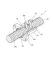
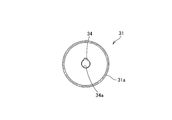
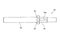
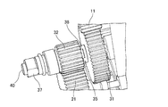
図1は、本発明の実施形態に係る伝達機構を用いたアクチュエータの構造を説明するための断面図であり、図2は、本発明の実施形態に係るアクチュエータに用いられるボールねじ装置の構造を説明するための一部断面図であり、図3は、本発明の実施形態に係る伝達機構に用いられる第一の回転部材の正面図であり、図4は、本発明の実施形態に係る伝達機構に用いられる第二の回転部材の側面図であり、図5は、本発明の実施形態に係る伝達機構に用いられる貫通軸の側面図であり、図6及び図7は、本発明の実施形態に係る伝達機構の構造を説明するための斜視図である。
図1に示すように、本実施形態に係る伝達機構30を用いたアクチュエータ1は、入力軸10を有する駆動源12と、出力軸20とを有しており、入力軸10と出力軸20との間に伝達機構30が介在している。なお、これらの構成部品は筺体2に収納されてアクチュエータ1を構成している。
駆動源12は、電動モータなど種々の要素部品を用いることができ、入力軸10に対して回転運動を行う回転力を付与している。また、入力軸10には、入力歯車11が取り付けられており、該入力歯車11によって、伝達機構30に回転力を伝達している。
出力軸20は、軸受22によって回転可能に保持されており、出力軸20に取り付けられた出力歯車21によって伝達機構30から回転力を付与される。
なお、出力軸20は、ボールねじ装置3を構成しており、出力軸20へ伝達機構30を介して回転力が付与されて回転することによって、この回転運動をナット23の直線運動に変換している。なお、ボールねじ装置3は、筺体2に取り付けられた外筒25に収納されており、外筒25の一端から伸縮自在に伸縮部24が配置されている。さらに、ナット23には、平行キー26が取り付けられており、該平行キー26が外筒25の内周に長手方向に沿って形成されたキー溝27と係合することでナット23の回転を規制している。
伸縮部24は、円筒状の部材であり、一端がナット23に取り付けられることで、ナット23の移動に伴って移動すると共に、内周側に出力軸20を収納可能に形成されている。このように、伸縮部24が円筒状に形成されることで、伸縮部24が外筒25内に収められた状態でも、出力軸20と伸縮部24とが干渉することがないので、アクチュエータ1をコンパクトに形成することが可能となる。
図2に示すように、本実施形態に係るアクチュエータ1に用いられるボールねじ装置3は、外周面に所定のリードで螺旋状の転動体転走溝20aが形成されてねじ軸として構成された出力軸20と、該出力軸20が貫通するナット孔23cを備え円筒形状に形成されると共に、ナット孔23cの内周面に出力軸20に形成された転動体転走溝20aと対向する負荷転動体転走溝23aが形成されたナット23とを備え、転動体転走溝20aと負荷転動体転走溝23aとの間に複数のボール29を配列して出力軸20とナット23とが螺合している。なお、ナット23は、円筒形状に限られず、例えば軸方向と直交する断面形状が外形矩形状等の筒状に形成しても構わない。
このように構成されたボールねじ装置3は、出力軸20とナット23との相対的な回転によってナット23が出力軸20の軸線方向に沿って運動するように構成されている。
ナット23は、鋼等の金属で円筒形状に形成されており、その外周面にはナット23を相手部品に固定するためのフランジ23bがナット23の径方向に延びて形成されている。また、ナット孔23cの軸線方向の両端にはシール部材28が取り付けられており、該シール部材28によって出力軸20とナット23との間に塵埃等が浸入することを防止すると共に、ボール29に塗布された潤滑剤がボールねじ装置3の外部に漏出することを防止することができる。
また、ナット23には、転動体転走溝20aを転走したボール29の進行方向を変えて転動体転走溝20aのもとの位置に戻す方向転換路が内周に形成されたリターンパイプ29aが取り付けられている。このリターンパイプ29aによって、転動体転走溝20aを出力軸20の周方向に転走したボール29がもとの位置に戻されることでボール29の無限循環を実現している。さらに、リターンパイプ29aは、ナット23の径方向に沿って穿孔された取付孔に挿入して固定されている。
伝達機構30は、第一の回転部材31と第二の回転部材32とを備えており、第一の回転部材31と第二の回転部材32とを同心配置するように、該第一の回転部材31および第二の回転部材32を貫通する貫通軸33によって組み合わされている。なお、本実施形態において、第一の回転部材31および第二の回転部材32は共に歯車である。
図3に示すように、第一の回転部材31は、外周に第一の歯部31aが形成され、その中心に上述した貫通軸33が貫通する中心孔34aが穿孔されている。また、中心孔34aには、切り欠き上の溝34が形成されている。
図4に示すように、第二の回転部材32は、外周に第二の歯部32aが形成され、一端に軸方向に延びる操作手段取付部37が形成され、他端面に第一の拘束部35が形成されている。さらに、第二の歯部32aと操作手段取付部37を貫通するように、貫通孔36が形成されている。なお、第一の拘束部35は、当該貫通孔36の外縁に沿って複数形成されており、軸方向に突出する爪部として形成されている。また、操作手段取付部37の外周には、第二の回転部材32を手動で回転させるための工具等を取り付けできるように工具に合わせた面取り等が施されている。
図5に示すように、貫通軸33は、長尺の円柱状部材であり、上述した第一の拘束部35と係合する第二の拘束部38が形成されている。具体的には、第二の拘束部38は、第一の拘束部35の爪部と対応するように当該爪部と係合する溝状の係合部として形成されている。
第二の拘束部38の軸方向の両端には、歯車取付部39及び延長部40が軸方向に延設しており、該歯車取付部39を第一の回転部材31の中心孔34aに挿入し、延長部40を第二の回転部材32の貫通孔36に挿入することで、伝達機構30として一体に組み合わせている。
また、歯車取付部39には、軸方向に沿ってキー溝39aが形成されており、当該キー溝39aに挿入された突起としてのキー44が第一の回転部材31に形成された溝34と係合することで、貫通軸33と第一の回転部材31とを一体に回転させることができるようになっている。
なお、第一の回転部材31は、貫通軸33と共に第二の回転部材32の貫通孔36に沿って軸方向に移動可能に配置されている。
さらに、貫通軸33は、付勢手段41によって第二の回転部材32側に付勢されている。付勢手段41は、貫通軸33を第二の回転部材32側に付勢することができればどのような部材を適用しても構わないが、例えばコイルスプリングを用いると好適である。
また、第二の回転部材32の操作手段取付部37は、筺体2の外部に突出しており、さらに、操作手段取付部37の端面からは、貫通軸33の延長部40が突出している。なお、第二の回転部材32は、筺体2にCクリップ等によって軸方向には移動不能に取り付けられている。
次に、図6及び7を参照して本実施形態に係る伝達機構30の動作について説明を行う。図6に示すように、通常使用される電動操作の状態では、付勢手段41によって貫通軸33が第二の回転部材32側に付勢されているので、貫通軸33に形成された第二の拘束部38と、第二の回転部材32に形成された第一の拘束部35とは互いに係合している。この状態では、第一の回転部材31と第二の回転部材32とが共に回転するので、入力歯車11の回転力が伝達機構30を介して出力歯車21に伝達される。
次に、手動操作への切り替えは、図7に示すように、操作手段取付部37から突出しているボタン状の延長部40を押し込むことで行う。第一の回転部材31は、上述したように軸方向に移動可能に取り付けられているので、延長部40を押し込むことで、第一の拘束部35と第二の拘束部38との係合が解除され、たとえ駆動源12の故障や入力軸10の固着などによって入力軸10が回転不能となった場合であっても第二の回転部材32を単独で回転させることができる。なお、第二の回転部材32の回転は、素手による作業を行っても構わないし、操作手段取付部37に所定の工具などの操作手段を取り付けることで回転させても構わない。このように構成することで小さな力で出力軸20に容易に回転させることができると共に、電動操作中は操作手段を取り外すことでアクチュエータの大きさをコンパクトに形成することができる。
このように、本実施形態に係る伝達機構30を用いたアクチュエータ1は、付勢部材41によって貫通軸33を付勢しているので、第二の回転部材32から突出した延長部40を押す作業だけで手動操作と電動操作とを切り替えることができる。このように構成することで、部品点数の削減を図ることができ、伝達装置30の全体の大きさをコンパクトに形成することができる。また、延長部40を押すだけで手動操作への切り替えができるので、従来の切り替え操作に比べて非常に簡便な操作で切り替え操作を行うことができる。
なお、本発明は、上記実施形態に限られることはなく、本発明の要旨を変更しない範囲において、種々の変更が可能である。例えば、本実施形態の伝達機構では、第一の拘束部と第二の拘束部とを爪部と係合部として構成した場合について説明を行ったが、第一の拘束部と第二の拘束部はこれに限られず、例えば摩擦板を用いて第一の回転部材と第二の回転部材とを一体に回転させるように構成しても構わない。
また、本実施形態では、第一の回転部材及び第二の回転部材を一対の歯車を用いて形成した場合について説明を行ったが、第一の回転部材及び第二の回転部材の形態はこれに限られず、例えば、複数の歯車を歯合させて減速機構を構成しても構わない。
また、本実施形態では、第一の回転部材及び第二の回転部材を歯車を用いこれらを互いに歯合させた場合について説明を行ったが、第一の回転部材及び第二の回転部材の形状はこれに限られず、例えば、第一の回転部材及び第二の回転部材をタイミングベルト車,スプロケット及びプーリ等で構成し、入力軸と第一の回転部材及び出力軸と第二の回転部材とを其々タイミングベルト,チェーン及びベルトを張渡して構成して駆動力の付与な構成としても構わない。
また、本実施形態では、ボールねじ装置としてリターンパイプを用いたボールねじ装置について説明を行ったが、ボールねじ装置はこれに限られず、例えばデフレクタを用いた無限循環式のボールねじ装置を採用しても構わないし、有限循環式のボールねじ装置又は、転動体を有さない摺動式を採用しても構わない。その様な変更又は改良を加えた形態も本発明の技術的範囲に含まれうることが、特許請求の範囲の記載から明らかである。
1 アクチュエータ, 10 入力軸, 12 駆動源, 20 出力軸, 30 伝達機構, 31 第一の回転部材, 32 第二の回転部材, 33 貫通軸, 34 溝, 35 第一の拘束部, 36 貫通孔, 38 第二の拘束部, 44 キー。
Claims (6)
- 入力軸からの駆動力を出力軸に伝達する伝達機構であって、
前記入力軸側から駆動力を付与される第一の回転部材と、
前記出力軸に駆動力を付与する第二の回転部材と、
前記第一の回転部材と共に回転し、前記第二の回転部材を前記第一の回転部材と同心配置するように貫通する貫通軸と、
前記第二の回転部材の前記第一の回転部材側に配されて前記第二の回転部材と共に回転する第一の拘束部と、
前記貫通軸と共に回転し、前記第一の拘束部と係脱自在に配置された第二の拘束部を備え、
前記貫通軸が前記第二の回転部材の一端から突出することを特徴とする伝達機構。 - 請求項1に記載の伝達機構において、
前記貫通軸を前記第二の回転部材側に付勢する付勢手段を備えることを特徴とする伝達機構。 - 請求項1又は2に記載の伝達機構において、
前記第一の回転部材と前記貫通軸とは、前記第一の回転部材と前記貫通軸のいずれか一方に軸方向に沿って形成された溝と、いずれか他方に形成された突起とが係合することを特徴とする伝達機構。 - 請求項1から3のいずれか1項に記載の伝達機構において、
前記第二の回転部材の一端には、操作手段が着脱可能に形成されることを特徴とする伝達機構。 - 請求項1から4のいずれか1項に記載の伝達機構において、
前記第一の拘束部は、前記第二の回転部材の端面から前記第一の回転部材に向かって突出する爪部であり、
前記第二の拘束部は、前記爪部と係合する係合部であることを特徴とする伝達機構。 - 入力軸と、
出力軸と、
前記入力軸からの駆動力を前記出力軸に伝達する請求項1から5のいずれか1項に記載の伝達機構とを備えることを特徴とするアクチュエータ。
Applications Claiming Priority (2)
| Application Number | Priority Date | Filing Date | Title |
|---|---|---|---|
| JP2013-097625 | 2013-05-07 | ||
| JP2013097625A JP2014219036A (ja) | 2013-05-07 | 2013-05-07 | 伝達機構及びこの伝達機構を用いたアクチュエータ |
Publications (1)
| Publication Number | Publication Date |
|---|---|
| WO2014181704A1 true WO2014181704A1 (ja) | 2014-11-13 |
Family
ID=51867186
Family Applications (1)
| Application Number | Title | Priority Date | Filing Date |
|---|---|---|---|
| PCT/JP2014/061671 Ceased WO2014181704A1 (ja) | 2013-05-07 | 2014-04-25 | 伝達機構及びこの伝達機構を用いたアクチュエータ |
Country Status (2)
| Country | Link |
|---|---|
| JP (1) | JP2014219036A (ja) |
| WO (1) | WO2014181704A1 (ja) |
Families Citing this family (1)
| Publication number | Priority date | Publication date | Assignee | Title |
|---|---|---|---|---|
| JP2016217506A (ja) * | 2015-05-25 | 2016-12-22 | Thk株式会社 | クラッチ付き伝達機構及びこの伝達機構を用いたアクチュエータ |
Citations (4)
| Publication number | Priority date | Publication date | Assignee | Title |
|---|---|---|---|---|
| JPS4324911Y1 (ja) * | 1965-07-30 | 1968-10-19 | ||
| JPS4523602Y1 (ja) * | 1967-12-20 | 1970-09-17 | ||
| JPS5899521A (ja) * | 1981-12-04 | 1983-06-13 | Ricoh Co Ltd | 回転部品の軸との結合構造 |
| JP3136565U (ja) * | 2007-08-03 | 2007-11-01 | 株式会社島津製作所 | 電動アクチュエータ |
-
2013
- 2013-05-07 JP JP2013097625A patent/JP2014219036A/ja active Pending
-
2014
- 2014-04-25 WO PCT/JP2014/061671 patent/WO2014181704A1/ja not_active Ceased
Patent Citations (4)
| Publication number | Priority date | Publication date | Assignee | Title |
|---|---|---|---|---|
| JPS4324911Y1 (ja) * | 1965-07-30 | 1968-10-19 | ||
| JPS4523602Y1 (ja) * | 1967-12-20 | 1970-09-17 | ||
| JPS5899521A (ja) * | 1981-12-04 | 1983-06-13 | Ricoh Co Ltd | 回転部品の軸との結合構造 |
| JP3136565U (ja) * | 2007-08-03 | 2007-11-01 | 株式会社島津製作所 | 電動アクチュエータ |
Also Published As
| Publication number | Publication date |
|---|---|
| JP2014219036A (ja) | 2014-11-20 |
Similar Documents
| Publication | Publication Date | Title |
|---|---|---|
| JP6539524B2 (ja) | 駆動力伝達機構 | |
| JP6246183B2 (ja) | シフト装置 | |
| CN104653736B (zh) | 行星滚动传动机构和具有所述行星滚动传动机构的致动器 | |
| US8596152B2 (en) | Rotary drum for a gear control device for a motor-vehicle gearbox and a gear control device for a motor-vehicle gearbox having such a drum | |
| US20190017598A1 (en) | Park-lock device for a vehicle transmission | |
| CN107763153A (zh) | 用于电动车辆的行星齿轮型两挡变速器 | |
| WO2015081950A3 (de) | Aktuator mit einem eine drehbewegung in eine lineare bewegung umwandelnden getriebe | |
| JP2017133606A (ja) | 電動リニアアクチュエータ | |
| JP2014219036A (ja) | 伝達機構及びこの伝達機構を用いたアクチュエータ | |
| JP4758371B2 (ja) | 動力伝達切換機構 | |
| US20220136600A1 (en) | Power tool with compliant shifting mechanism | |
| TW201727091A (zh) | 可傳達扭矩之線性軸襯 | |
| JP2007040424A (ja) | 電動リニアアクチュエータ | |
| JP2012171452A (ja) | パーキングロック機構 | |
| JP5069595B2 (ja) | 移動機構、光学装置 | |
| US11378183B2 (en) | Gearshift actuator | |
| JP2013245714A (ja) | 変速機 | |
| WO2011078009A1 (ja) | 電動リニアアクチュエータ | |
| CN112283304A (zh) | 一种两级手摇精密驱动装置 | |
| WO2016189984A1 (ja) | クラッチ付き伝達機構及びこの伝達機構を用いたアクチュエータ | |
| JP5042920B2 (ja) | 駆動伝達装置 | |
| JP6699227B2 (ja) | 動力伝達装置 | |
| JP2007032703A (ja) | 電動リニアアクチュエータ | |
| AU2019365306A1 (en) | Actuating mechanism, clutch actuator and transmission actuator with improved vibration behaviour | |
| JP2010228037A (ja) | 駆動力解放装置 |
Legal Events
| Date | Code | Title | Description |
|---|---|---|---|
| 121 | Ep: the epo has been informed by wipo that ep was designated in this application |
Ref document number: 14794435 Country of ref document: EP Kind code of ref document: A1 |
|
| NENP | Non-entry into the national phase |
Ref country code: DE |
|
| 122 | Ep: pct application non-entry in european phase |
Ref document number: 14794435 Country of ref document: EP Kind code of ref document: A1 |