WO2014174948A1 - 太陽電池モジュール - Google Patents
太陽電池モジュール Download PDFInfo
- Publication number
- WO2014174948A1 WO2014174948A1 PCT/JP2014/057658 JP2014057658W WO2014174948A1 WO 2014174948 A1 WO2014174948 A1 WO 2014174948A1 JP 2014057658 W JP2014057658 W JP 2014057658W WO 2014174948 A1 WO2014174948 A1 WO 2014174948A1
- Authority
- WO
- WIPO (PCT)
- Prior art keywords
- solar cell
- cell panel
- cell module
- fitting
- receiving surface
- Prior art date
- Legal status (The legal status is an assumption and is not a legal conclusion. Google has not performed a legal analysis and makes no representation as to the accuracy of the status listed.)
- Ceased
Links
Images




Classifications
-
- H—ELECTRICITY
- H02—GENERATION; CONVERSION OR DISTRIBUTION OF ELECTRIC POWER
- H02S—GENERATION OF ELECTRIC POWER BY CONVERSION OF INFRARED RADIATION, VISIBLE LIGHT OR ULTRAVIOLET LIGHT, e.g. USING PHOTOVOLTAIC [PV] MODULES
- H02S30/00—Structural details of PV modules other than those related to light conversion
- H02S30/10—Frame structures
-
- Y—GENERAL TAGGING OF NEW TECHNOLOGICAL DEVELOPMENTS; GENERAL TAGGING OF CROSS-SECTIONAL TECHNOLOGIES SPANNING OVER SEVERAL SECTIONS OF THE IPC; TECHNICAL SUBJECTS COVERED BY FORMER USPC CROSS-REFERENCE ART COLLECTIONS [XRACs] AND DIGESTS
- Y02—TECHNOLOGIES OR APPLICATIONS FOR MITIGATION OR ADAPTATION AGAINST CLIMATE CHANGE
- Y02E—REDUCTION OF GREENHOUSE GAS [GHG] EMISSIONS, RELATED TO ENERGY GENERATION, TRANSMISSION OR DISTRIBUTION
- Y02E10/00—Energy generation through renewable energy sources
- Y02E10/50—Photovoltaic [PV] energy
Definitions
- the present invention relates to a solar cell module.
- the solar cell module is generally composed of a solar cell panel and a frame. 1394069804161_0
- the solar cell module 50 includes a solar cell panel 51 and a frame body 52.
- a solar cell 51d made of silicon, a back side sealing layer 51c made of EVA, and a back side sealing weather resistant film 51e are laminated in this order, and have a super straight type structure that is integrally laminated.
- the solar cell panel 51 is formed as a thin plate having a rectangular shape having a weather resistance and a thickness of about 5 mm.
- the solar battery cell 51d may be made of single crystal silicon, amorphous silicon, or the like.
- the end surface sealing member 53 has a frame shape formed along the outer shape of the end portion 51f of the solar cell panel 51, and is formed of an elastomer resin or a resin such as a silicon resin.
- the end surface sealing member 53 includes an upper sealing piece 53 a that contacts the front surface side of the solar cell panel 51, a lower sealing piece 53 b that contacts the back surface side of the solar cell panel 51, and an end of the solar cell panel 51. It is formed in a substantially U-shaped cross section comprising a lateral sealing piece 53c that contacts the end surface of the portion 51f, and this U-shaped portion constitutes a groove 53f (sealing groove).
- the end portion 51f of the solar cell panel 51 is fitted into the groove portion 53f and sealed.
- the present invention has been made in view of the above-described problems, and provides a solar cell module in which sand and dust are unlikely to collect on the light receiving surface.
- the solar cell module of the present invention is a solar cell module including a solar cell panel and a frame body that is fitted to an end portion of the solar cell panel and supports the solar cell. It has a fitting part for fitting, the fitting part has an edge part, the end part of the solar cell panel is fitted with the fitting part, and the light receiving surface of the solar cell panel is on the edge part. It comes into contact.
- the solar cell module of the present invention includes one in which the edge portion is extended from the upper side portion of the fitting portion and is inclined toward the solar cell panel toward the tip.
- the solar cell module of the present invention includes one in which the edge portion is tapered.
- the solar cell module of this invention has a 1st inclination part and a 2nd inclination part with which the lower wall of the fitting part inclined with respect to the light-receiving surface of a solar cell panel, and 1st inclination The portion is inclined corresponding to the inclination of the edge portion, and the second inclined portion includes an inclination corresponding to the shape of the back surface of the end portion of the solar cell.
- the solar cell module of the present invention has a tape-like elastic member attached to the end portion of the solar cell panel, and the elastic member has a light receiving surface side, an end surface, and a back surface side of the end portion of the solar cell panel. Including coverings.
- sand and dust are less likely to accumulate on the surface of the solar cell panel, and a highly reliable solar cell module can be provided.
- FIG. 1 It is a top view which shows the solar cell module of this invention. It is sectional drawing of the solar cell panel edge part which comprises the solar cell module of this invention. It is sectional drawing of the frame used for the solar cell module of this invention. It is explanatory drawing explaining the process of a fitting with the solar cell panel used for the solar cell module of this invention, and a frame. It is sectional drawing of the edge part of the solar cell module of this invention. It is explanatory drawing which shows another embodiment of the solar cell panel edge part which comprises the solar cell module of this invention. It is sectional drawing of the edge part of the conventional solar cell module.
- FIG. 1 is a plan view showing a solar cell module of the present invention.
- the solar cell module 1 includes a solar cell panel 10 and a frame body 20.
- a frame 20 for supporting the solar cell panel 10 is fitted and attached to each side of the solar cell panel 10 to form the solar cell module 1.
- the frame 20 is made of a metal having weather resistance such as aluminum or stainless steel.
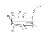
- FIG. 2 is a cross-sectional view of the end portion of the solar cell panel constituting the solar cell module of the present invention.
- a solar cell panel 10 includes a photoelectric conversion such as a crystalline solar cell or an amorphous solar cell between a light-receiving surface glass 11 which is a light-transmitting insulating substrate on the light-receiving surface side and a weather-resistant film 12 on the back surface side.
- the element 13 is formed by being sealed together with a transparent resin 14 such as PVB (polyvinyl butyral) or EVA.
- the end of the back surface of the solar cell panel 10 has an inclined shape with the thickness of the transparent resin 14 becoming thinner as it approaches the end surface. For example, if the thickness of the light receiving surface glass 11 is 2.8 mm and the thickness of the panel at the center of the panel is 4.47 mm, the thickness of the panel end is 3.5 mm.
- An elastic member 15 made of a tape using an elastic body such as butyl rubber is attached to the end of the solar cell panel 10 so as to cover the end.
- Butyl rubber is suitable as a material for the elastic member 15 because it deforms flexibly and has adhesiveness.
- the elastic member 15 includes a light receiving surface portion 15a, an end surface portion 15b, and a back surface portion 15c, and covers the light receiving surface, the end surface, and the back surface of the end portion of the solar cell panel, respectively.
- a tape having a width of 17 mm is used as the elastic member 15
- the elastic member 15 is bonded from the inside of the light receiving surface glass 11 to the end surface and the back surface from the inside of 6.75 mm.
- the thickness of the uncompressed tape is about 0.8 to 1.2 mm.
- FIG. 3 is a cross-sectional view of a frame body that fits into a solar cell panel used in the solar cell module of the present invention.
- a frame body 20 is provided on a base portion 21, a box-shaped portion 22 provided on the base portion 21, and the box-shaped portion 22, and is fitted to the frame body 20 for fitting with the solar cell panel 10. It consists of a joint 23.
- the upper wall 24 of the box-shaped part 22 is shared with the lower wall 26 of the fitting part 23.
- the upper wall 24 of the fitting part 23 includes an upper side part 24a and an edge part 24b.
- the upper side portion 24 a is a portion having a predetermined length from the back of the fitting portion 23 and is formed in parallel to the base portion 21.
- the edge portion 24b is a portion extending from the upper side portion 24a, and is bent so as to approach the base portion 21 toward the tip.
- the tip of the edge portion 24b is tapered, and the angle formed with the solar cell panel 10 is an obtuse angle when contacting the solar cell panel 10.
- the tip of the upper side 24a and the edge 24b has a height difference of about 0.5 mm, for example. Due to this height difference, a space 25 is formed immediately below the upper side portion 24a.
- edge part 24b extended from the upper side part 24a of the fitting part 23 is bent toward the base part 21 toward the tip of the edge part 24b, the frame 20 and the solar cell panel 10 are fitted. At this time, the edge portion 24b is in contact with the light receiving surface glass 11, and the light receiving surface portion 15a of the elastic member 15 attached to the solar cell panel 10 in the space 25 formed by the height difference between the tip of the edge portion 24b and the upper side portion 24a. Will fit.
- the lower wall 26 of the fitting part 23 is inclined from the fitting part inlet 27 toward the back part 28.
- the first inclined portion 26a in the vicinity of the fitting portion entrance 27 has an inclination corresponding to the shape of the edge portion 24b, and can secure a width necessary for the solar cell panel 10 to be inserted.
- the second inclined portion 26 b in a portion near the back portion 28 of the fitting portion is formed in a shape along the shape of the end portion of the solar cell panel 10. That is, it inclines corresponding to the shape of the end back surface of the solar cell panel 10 and becomes narrower as it approaches the back portion 28 of the fitting portion.
- the lower wall 26 of the fitting part 23 has two types of inclined surfaces, the first inclined part 26a and the second inclined part 26b.
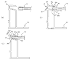
- FIG. 4 is an explanatory diagram for explaining the process of fitting the solar cell panel and the frame.
- FIG. 4A is a diagram showing a positional relationship between the solar cell panel and the frame body before insertion.
- the end portion of the solar cell panel 10 is inserted almost horizontally into the fitting portion 23 of the frame body 20.
- FIG.4 (b) is a figure which shows a mode that a solar cell panel is inserted in a frame.
- the elastic member 15 of the solar cell panel 10 is inserted toward the back portion 28 of the fitting portion while being compressed by the upper wall 24 and the lower wall 26.
- the first inclined portion 26a in the vicinity of the fitting portion entrance 27 is inclined corresponding to the shape of the edge portion 24b and is higher toward the back, whereas the tip of the edge portion 24b is lower.
- the solar cell panel 10 is inserted so as to press the back surface portion 15c of the elastic member 15 against the first inclined portion 26a.
- FIG.4 (c) is a figure which shows a mode that a solar cell panel is further inserted in a frame.
- the solar cell panel 10 is inserted so as to press the back surface portion 15c of the elastic member 15 against the second inclined portion 26b.
- the light receiving surface portion 15 a of the elastic member 15 expands along the shape of the upper wall 24 as it is inserted into the fitting portion 23.
- the elastic member 15 is in a state where the back surface portion 15c is compressed rather than the light receiving surface portion 15a directly below the upper side portion 24a. .
- FIG. 5 is a cross-sectional view of the end portion of the solar cell module of the present invention, showing the A-A ′ cross section in FIG.
- the back surface portion 15c of the elastic member 15 has a substantially constant thickness. Thus, the pressure is applied to the elastic member 15 evenly.
- the back surface portion 15c of the elastic member 15 is pressed against the lower wall 26 and inserted while being compressed.
- the light receiving surface portion 15a of the elastic member 15 fits in the space 25 immediately below the upper side portion 24a when the solar cell panel 10 is inserted to the back. That is, when the light-receiving surface portion 15a is inserted up to the back portion 28 of the fitting portion, the light-receiving surface portion 15a enters the space 25 and expands, and the compression rate decreases. Therefore, in the state where the force to be inserted is applied, the back surface portion 15c is compressed more than the light receiving surface portion 15a.
- the back surface portion 15c has a higher compression rate and a stronger repulsive force than the light receiving surface portion 15a. Therefore, when the application of the force to be inserted is stopped, the solar cell panel 10 moves in the direction of the upper wall 24, and the light receiving surface glass 11 of the solar cell panel 10 is edged by the repulsive force of the back surface portion 15c. 24b is pressed against and abuts.
- the thickness of the tape which is an elastic member after the insertion is completed, is about 0.4 to 0.6 mm.
- the angle between the edge portion 24b and the light receiving surface glass 11 is an obtuse angle, it is difficult for sand and dust to accumulate, so that the power generation performance of the solar cell module 1 is prevented from being deteriorated due to the accumulation of sand and dust on the light receiving surface. be able to.
- the durability of the solar cell module 1 can be improved. Furthermore, sand and dust deposited on the solar cell module 1 are easily washed away by rainwater.
- the elastic member 15 at the end of the solar cell panel 10 is formed so as to cover the end of the solar cell panel, the end of the solar cell panel 10 is protected and water or the like enters the end. Can be surely prevented. Moreover, since it closely_contact
- the solar cell panel 10 is adhered to the frame body 20 by using a sheet-like elastic member 15 having an adhesive layer on both sides as a member for bringing the solar cell panel 10 and the fitting portion 23 of the frame body 20 into close contact with each other. And can be securely fixed to the frame 20. Further, by using a tape-like member as the elastic member 15, the position and thickness of the elastic member 15 and the amount of the elastic member 15 can be reliably controlled. Therefore, the light receiving surface portion 15a of the elastic member 15 can be securely stored in the space 25 immediately below the upper side portion 24a of the upper wall 24 of the fitting portion 23 and can be fixed so as to press the solar cell panel 10 toward the upper wall 24.
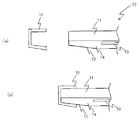
- FIG. 6 is explanatory drawing which shows another embodiment of the solar cell panel edge part which comprises the solar cell module of this invention.
- the sealing cap 16 is formed to match the shape of the end of the solar cell panel 10.
- the sealing cap 16 is inserted into the end portion of the solar cell panel 10 to protect the end portion of the solar cell panel 10 and corresponds to the tape in Example 1 as an elastic member. It has the function to do.
Landscapes
- Photovoltaic Devices (AREA)
Abstract
受光面に砂や塵がたまりにくい太陽電池モジュールを提供する。 太陽電池パネルと、太陽電池パネルの端部と嵌合して太陽電池を支持するための枠体からなる太陽電池モジュールにおいて、枠体は、太陽電池パネルと嵌合するための嵌合部を有してなり、嵌合部はエッジ部を有し太陽電池パネルの端部は、嵌合部と嵌合するとともに、太陽電池パネルの受光面は、エッジ部に当接してなる太陽電池モジュール。
Description
本発明は太陽電池モジュールに関するものである。
太陽電池モジュールは、一般的に、太陽電池パネルと枠体とにより構成されている。
1394069804161_0
図7において、太陽電池モジュール50は太陽電池パネル51と枠体52からなる。太陽電池パネル51の表面側である受光面ガラス51a上(図面では下側となっている)に、熱硬化性樹脂であるEVA(エチレンビニルアセテート)でなる受光面側封止層51b、多結晶シリコンにより形成された太陽電池セル51d、EVAでなる裏面側封止層51c、裏面側封止耐候性フィルム51eがこの順に積層されて、一体化ラミネート加工されたスーパーストレート型構造である。このように、太陽電池パネル51は、耐候性が確保された矩形状で、厚さが5mm程度の薄板として構成されている。尚、上記太陽電池セル51dは、単結晶シリコンやアモルファスシリコン等で形成されたものであってもよい。
1394069804161_0
図7において、太陽電池モジュール50は太陽電池パネル51と枠体52からなる。太陽電池パネル51の表面側である受光面ガラス51a上(図面では下側となっている)に、熱硬化性樹脂であるEVA(エチレンビニルアセテート)でなる受光面側封止層51b、多結晶シリコンにより形成された太陽電池セル51d、EVAでなる裏面側封止層51c、裏面側封止耐候性フィルム51eがこの順に積層されて、一体化ラミネート加工されたスーパーストレート型構造である。このように、太陽電池パネル51は、耐候性が確保された矩形状で、厚さが5mm程度の薄板として構成されている。尚、上記太陽電池セル51dは、単結晶シリコンやアモルファスシリコン等で形成されたものであってもよい。
端面封止部材53は、太陽電池パネル51の端部51fの外形に沿って形成された枠形状をしており、エラストマー樹脂や、シリコン樹脂等の樹脂により形成されている。又、端面封止部材53は、太陽電池パネル51の表面側に当接する上側封止片53aと、太陽電池パネル51の裏面側に当接する下側封止片53bと、太陽電池パネル51の端部51fの端面に当接する横側封止片53cとからなる断面略コ字状に形成されており、このコ字状の部分が溝部53f(封止用溝部)を構成している。この溝部53fに、太陽電池パネル51の端部51fが嵌め込まれて封止される。
しかしながら、前述のような構造では、枠体と受光面ガラスの間の隙間に充填されている封止部材の厚さによって、枠体と受光面ガラスの間に段差ができる。段差には、砂や塵を吸着しやすく柔らかい封止樹脂が詰まっており、その表面に砂や塵が吸着し、封止樹脂が起点となって汚れが光電変換素子全面まで及んで太陽電池モジュールの発電性能を損なう怖れがあった。また、段差に溜まった砂や塵は、降雨などによっても取り除きにくく、それらがガラス表面に移動して、太陽電池前面のガラスが汚れ、発電量が低下する原因となっていた。
本発明は、上述の問題点を鑑みなされたものであり、受光面に砂や塵がたまりにくい太陽電池モジュールを提供するものである。
本発明の太陽電池モジュールは、太陽電池パネルと、太陽電池パネルの端部と嵌合して太陽電池を支持するための枠体からなる太陽電池モジュールであって、枠体は、太陽電池パネルと嵌合するための嵌合部を有し、嵌合部はエッジ部を有し、太陽電池パネルの端部は、嵌合部と嵌合するとともに、太陽電池パネルの受光面は、エッジ部に当接してなるものである。
また、本発明の太陽電池モジュールは、エッジ部は、嵌合部の上辺部から延設されてなり、先端に向かって太陽電池パネルの方に傾斜して形成されてなるものを含む。
また、本発明の太陽電池モジュールは、エッジ部は、先細であるものを含む。
また、本発明の太陽電池モジュールは、嵌合部の下壁は、太陽電池パネルの受光面に対して傾斜した、第1の傾斜部と第2の傾斜部とを有し、第1の傾斜部は、エッジ部の傾斜と対応して傾斜してなり、第2の傾斜部は、太陽電池の端部の裏面の形状に対応して傾斜してなるものを含む。
また、本発明の太陽電池モジュールは、太陽電池パネルの端部にテープ状の弾性部材が貼り付けられてなり、弾性部材は、太陽電池パネルの端部の、受光面側と端面と裏面側を覆うものを含む。
本発明により、砂や塵が太陽電池パネル表面に堆積しにくくなり、信頼性の高い太陽電池モジュールを提供することができる。
(実施の形態1)
以下、図面を参照しつつ、本発明の実施の形態に係る説明する。以下の説明では同一の部品には同一の符号を付してある。それらの名称および機能も同じである。したがって、それらについて詳細な説明は繰り返さない。
以下、図面を参照しつつ、本発明の実施の形態に係る説明する。以下の説明では同一の部品には同一の符号を付してある。それらの名称および機能も同じである。したがって、それらについて詳細な説明は繰り返さない。
図1は、本発明の太陽電池モジュールを示す平面図である。図1において、太陽電池モジュール1は、太陽電池パネル10と枠体20からなる。太陽電池パネル10の各辺には、端部に太陽電池パネル10を支持するための枠体20が嵌めこまれて取り付けられ、太陽電池モジュール1を形成している。枠体20は、アルミニウムやステンレスなど耐侯性のある金属が用いられる。
図2は、本発明の太陽電池モジュールを構成する太陽電池パネル端部の断面図である。図2において、太陽電池パネル10は、受光面側の透光性絶縁基板である受光面ガラス11と、裏面側の耐候性フィルム12の間に、結晶系太陽電池やアモルファス太陽電池などの光電変換素子13をPVB(ポリビニルブチラール)やEVAなどの透明樹脂14とともに封止して形成される。封止はラミネータを用いて行われるが、ラミネート工程において、EVAが加熱されて溶けて流動化し、端部のEVAは外に逃げるよう移動するため、裏面の形状が、端にいくにつれ薄くなるように形成される。そのため、太陽電池パネル10の裏面の端部は、端面に近づくにしたがって、透明樹脂14の厚さが薄くなり、傾斜した形状を有している。例えば、受光面ガラス11の厚みを2.8mm、パネル中央部のパネルの厚さを4.47mmとすると、パネル端部の厚みは3.5mmである。
太陽電池パネル10の端部には、ブチルゴムなどの弾性体を使用したテープなどで構成された弾性部材15が端部を覆うように貼り付けられている。ブチルゴムは柔軟に変形し、粘着性もあるので、弾性部材15の材料として好適である。
弾性部材15は、受光面部15a、端面部15b、裏面部15cからなり、それぞれ太陽電池パネル端部の受光面、端面、および裏面を覆っている。例えば、弾性部材15として、幅が17mmのテープを使用する場合、受光面ガラス11の端から6.75mm内側のところから、端面、裏面にわたって接着されている。また、圧縮しない状態のテープの厚みは0.8~1.2mm程度である。弾性部材15として、テープ状の部材を使用することにより、均一な厚さの弾性部材を、正確な位置に配置することができる。
図3は、本発明の太陽電池モジュールに使用される太陽電池パネルと嵌合する枠体の断面図である。図3において、枠体20は、基部21と、基部21上に設けられた箱状部22と、箱状部22上に設けられ、枠体20に太陽電池パネル10と嵌合するための嵌合部23からなる。箱状部22の上壁24は嵌合部23の下壁26と共有している。
嵌合部23の上壁24は、上辺部24aとエッジ部24bからなる。上辺部24aは、嵌合部23の奥から所定長さの部分であって、基部21に対して平行に形成されている。エッジ部24bは、上辺部24aから延設された部分であって、先端にむかうにつれ、基部21に近づくように曲がっている。エッジ部24bの先端は、先細に形成されており、太陽電池パネル10に当接したとき、太陽電池パネル10となす角度が鈍角になるようになっている。上辺部24aと、エッジ部24bの先端は、例えば0.5mm程度の高さの差がある。この高さの差によって上辺部24a直下に空間25が形成される。
嵌合部23の上辺部24aから延設されたエッジ部24bは、エッジ部24bの先端に向かうに従って、基部21の方に曲がっているので、枠体20と太陽電池パネル10を嵌合させたとき、エッジ部24bは受光面ガラス11と当接し、エッジ部24bの先端と上辺部24aの高さの差でできた空間25に太陽電池パネル10に貼り付けられた弾性部材15の受光面部15aが収まることになる。
嵌合部23の下壁26は、嵌合部入口27から奥部28に向かって傾斜している。嵌合部入口27付近の第1の傾斜部26aは、エッジ部24bの形状に対応する傾斜を有しており、太陽電池パネル10が挿入されるのに必要な幅を確保することができる。また、嵌合部の奥部28に近い部分の第2の傾斜部26bは、太陽電池パネル10の端部の形状に沿った形状に形成されている。すなわち、太陽電池パネル10の端部裏面の形状に対応して傾斜してなり、嵌合部の奥部28に近づくにしたがって狭くなっている。このように、嵌合部23の下壁26は第1の傾斜部26aと、第2の傾斜部26bの2種類の傾斜面を有している。
図4は、太陽電池パネルと、枠体との嵌合の過程を説明する説明図である。
図4(a)は、挿入前の太陽電池パネルと枠体との位置関係を示す図である。太陽電池パネル10の端部は、枠体20の嵌合部23にほぼ水平に挿入される。
図4(b)は、太陽電池パネルが枠体に挿入される様子を示す図である。太陽電池パネル10の弾性部材15は、上壁24と下壁26に圧縮されながら、嵌合部の奥部28に向けて挿入される。嵌合部入口27付近の第1の傾斜部26aは、エッジ部24bの形状に対応して傾斜し、奥に向かって高くなっているのに対し、エッジ部24bの先端は低くなっているので、太陽電池パネル10は、弾性部材15の裏面部15cを、第1の傾斜部26aに押し付けるようにして挿入される。
図4(c)は、太陽電池パネルが枠体にさらに挿入される様子を示す図である。太陽電池パネル10は、弾性部材15の裏面部15cを、第2の傾斜部26bに押し付けるようにして挿入される。一方、弾性部材15の受光面部15aは、嵌合部23に挿入されるに従い、上壁24の形状に沿って拡張する。その結果、太陽電池パネル10が嵌合部の奥部28付近まで挿入されたとき、弾性部材15は、上辺部24a直下の受光面部15aよりも、裏面部15cの方が圧縮された状態になる。
図5は、本発明の太陽電池モジュールの端部の断面図であり、図1におけるA-A’断面を示すものである。太陽電池パネル10を嵌合部23の奥部28まで挿入すると弾性部材15の受光面部15aは、上壁24と密着する。また、弾性部材15の端面部15bは、奥壁29と密着する。また、弾性部材15の裏面部15cは、下壁26と密着する。
太陽電池パネル10の裏面側端部と第2の傾斜部26bの形状がほぼ同じなので、太陽電池パネル10を奥部28まで挿入したとき、弾性部材15の裏面部15cは、ほぼ一定の厚さになり、均等に弾性部材15に圧力がかかるようになる。
太陽電池パネル10を枠体20と嵌合させる過程において、弾性部材15の裏面部15cは、下壁26に押し付けられて圧縮されながら挿入される。一方、弾性部材15の受光面部15aは、太陽電池パネル10を奥まで挿入すると、上辺部24a直下の空間25に収まる。すなわち、受光面部15aは、嵌合部の奥部28まで挿入したとき、空間25に入り込んで拡張し、圧縮率が小さくなる。そのため、挿入しようとする力を加えたままの状態では、受光面部15aよりも、裏面部15cの方が圧縮された状態になる。すなわち、裏面部15cの方が、受光面部15aよりも圧縮率が高く反発力が強い。そのため、挿入しようとする力を加えるのを止めると、太陽電池パネル10は、上壁24の方向に移動し、太陽電池パネル10の受光面ガラス11は、裏面部15cの反発力によって、エッジ部24bに押し付けられて当接する。挿入完了後の弾性部材であるテープの厚さは0.4~0.6mm程度である。
受光面ガラス11と、エッジ部24bが当接しているので、受光面において枠体20の嵌合部23と太陽電池パネル10の間隙はない。したがって、当接している箇所から内側へは、砂や塵が侵入する恐れはなく、エッジ部24bより内側に配置された弾性部材15は、砂やほこりにさらされない。その結果、受光面ガラス11上には、弾性部材15に付着した砂や塵が移動してくることはない。さらに、エッジ部24bと受光面ガラス11の角度は鈍角になっているため砂や塵が堆積しにくくなるので、受光面への砂や塵の堆積による太陽電池モジュール1の発電性能の低下を防ぐことができる。
また、受光面ガラス11と、エッジ部24bとが当接している箇所から内側には雨水が浸入しにくくなるので、太陽電池モジュール1の耐久性を向上させることができる。さらに、雨水によって、太陽電池モジュール1上に堆積した砂や塵が洗い流されやすくなる。
雨水が蒸発すると雨水に含まれていた塵やほこりが、雨水がたまっていた個所に付着することがあるが、エッジ部24bは先細に形成され、エッジ部24bと受光面ガラス11の角度は鈍角になっているため、受光面ガラス11との当接している箇所に水滴などがたまりにくい。そのため水がスムーズに流れ、雨水がとどまりにくいので、塵やほこりがエッジ部24bに堆積しにくくなる。
また、太陽電池パネル10の端部の弾性部材15は、太陽電池パネル端部を覆うように形成されているので、太陽電池パネル10の端部を保護するとともに、端部への水などの侵入を確実に防ぐことができる。また、枠体20の嵌合部23に密着しているので、嵌合部23と弾性部材15の間への水の浸入を防止することができ、太陽電池モジュール1の耐久性を高めることができる。
さらに、太陽電池パネル10と枠体20の嵌合部23とを密着させるための部材として、両面に接着層のあるシート状の弾性部材15用いることにより、太陽電池パネル10を枠体20に密着させて確実に枠体20に固定することができる。また、弾性部材15としてテープ状の部材を用いることにより、弾性部材15の位置や厚さおよび弾性部材15の量を確実にコントロールすることができる。そのため、弾性部材15の受光面部15aが嵌合部23の上壁24の上辺部24a直下の空間25に確実に収めることができるとともに、太陽電池パネル10を上壁24方向に押し付けるように固定できるので、受光面ガラス11をエッジ部24bに確実に当接させることができる。
(実施の形態2)
図6は、本発明の太陽電池モジュールを構成する太陽電池パネル端部の別の実施の形態を示す説明図である。図6(a)において、封止キャップ16は、太陽電池パネル10の端部の形状に合うように形成されている。図6(b)に示されるように、封止キャップ16を太陽電池パネル10の端部に挿入することで太陽電池パネル10の端部を保護するとともに、弾性部材として実施例1におけるテープに対応する機能を有するものである。
(実施の形態2)
図6は、本発明の太陽電池モジュールを構成する太陽電池パネル端部の別の実施の形態を示す説明図である。図6(a)において、封止キャップ16は、太陽電池パネル10の端部の形状に合うように形成されている。図6(b)に示されるように、封止キャップ16を太陽電池パネル10の端部に挿入することで太陽電池パネル10の端部を保護するとともに、弾性部材として実施例1におけるテープに対応する機能を有するものである。
今回開示された実施の形態は、すべての点で例示であって制限的なものではないと考えられるべきである。本発明の範囲は上記した説明ではなくて特許請求の範囲によって示され、特許請求の範囲と均等の意味および範囲内でのすべての変更が含まれることが意図される。
1 太陽電池モジュール
10 太陽電池パネル
11 受光面ガラス
12 耐候性フィルム
13 光電変換素子
14 透明樹脂
15 弾性部材
15a 受光面部
15b 端面部
15c 裏面部
20 枠体
21 基部
22 箱状部
23 嵌合部
24 上壁
24a 上辺部
24b エッジ部
25 空間
26 下壁
26a 第1の傾斜部
26b 第2の傾斜部
27 嵌合部入口
28 奥部
29 奥壁
10 太陽電池パネル
11 受光面ガラス
12 耐候性フィルム
13 光電変換素子
14 透明樹脂
15 弾性部材
15a 受光面部
15b 端面部
15c 裏面部
20 枠体
21 基部
22 箱状部
23 嵌合部
24 上壁
24a 上辺部
24b エッジ部
25 空間
26 下壁
26a 第1の傾斜部
26b 第2の傾斜部
27 嵌合部入口
28 奥部
29 奥壁
Claims (5)
- 太陽電池パネルと、前記太陽電池パネルの端部と嵌合して太陽電池を支持するための枠体からなる太陽電池モジュールであって、
前記枠体は、太陽電池パネルと嵌合するための嵌合部を有し、
前記嵌合部はエッジ部を有し
前記太陽電池パネルの端部は、前記嵌合部と嵌合するとともに、前記太陽電池パネルの受光面は、前記エッジ部に当接してなる太陽電池モジュール。 - 前記エッジ部は、前記嵌合部の上辺部から延設されてなり、先端に向かって太陽電池パネルの方に傾斜して形成されてなる請求項1に記載の太陽電池モジュール。
- 前記エッジ部は、先細である請求項1または2に記載の太陽電池モジュール。
- 前記嵌合部の下壁は、前記太陽電池パネルの受光面に対して傾斜した、第1の傾斜部と第2の傾斜部とを有し、
前記第1の傾斜部は、前記エッジ部の傾斜と対応して傾斜してなり、
前記第2の傾斜部は、前記太陽電池の端部の裏面の形状に対応して傾斜してなる、
請求項1から3のいずれかに記載の太陽電池モジュール。 - 前記太陽電池パネルの端部にテープ状の弾性部材が貼り付けられてなり、
前記弾性部材は、前記太陽電池パネルの端部の、受光面側と端面と裏面側を覆う、請求項1から4のいずれかに記載の太陽電池モジュール。
Priority Applications (1)
| Application Number | Priority Date | Filing Date | Title |
|---|---|---|---|
| CN201490000592.0U CN205160453U (zh) | 2013-04-23 | 2014-03-20 | 太阳电池模块 |
Applications Claiming Priority (2)
| Application Number | Priority Date | Filing Date | Title |
|---|---|---|---|
| JP2013090074A JP6215562B2 (ja) | 2013-04-23 | 2013-04-23 | 太陽電池モジュール |
| JP2013-090074 | 2013-04-23 |
Publications (1)
| Publication Number | Publication Date |
|---|---|
| WO2014174948A1 true WO2014174948A1 (ja) | 2014-10-30 |
Family
ID=51791532
Family Applications (1)
| Application Number | Title | Priority Date | Filing Date |
|---|---|---|---|
| PCT/JP2014/057658 Ceased WO2014174948A1 (ja) | 2013-04-23 | 2014-03-20 | 太陽電池モジュール |
Country Status (3)
| Country | Link |
|---|---|
| JP (1) | JP6215562B2 (ja) |
| CN (1) | CN205160453U (ja) |
| WO (1) | WO2014174948A1 (ja) |
Cited By (3)
| Publication number | Priority date | Publication date | Assignee | Title |
|---|---|---|---|---|
| CN109792229A (zh) * | 2016-09-30 | 2019-05-21 | 松下知识产权经营株式会社 | 太阳能电池模块、框架 |
| EP4625813A1 (en) * | 2024-03-29 | 2025-10-01 | Jinko Solar Co., Ltd. | Photovoltaic module |
| EP4625812A1 (en) * | 2024-03-29 | 2025-10-01 | Jinko Solar Co., Ltd | Photovoltaic module |
Families Citing this family (2)
| Publication number | Priority date | Publication date | Assignee | Title |
|---|---|---|---|---|
| DE202015002312U1 (de) * | 2015-03-26 | 2015-04-08 | Solarworld Ag | Ramenprofilleiste für Solarzelllaminate, gerahmtes Solarmodul und Befestigungssystem für Solarmodule |
| KR102159900B1 (ko) * | 2020-02-17 | 2020-09-24 | 이선찬 | 조립식 건물의 지붕으로 누수 방지되게 설치되는 태양광패널의 지지프레임. |
Citations (4)
| Publication number | Priority date | Publication date | Assignee | Title |
|---|---|---|---|---|
| JP2000243998A (ja) * | 1999-02-24 | 2000-09-08 | Sanyo Electric Co Ltd | 太陽電池モジュール |
| JP2008085132A (ja) * | 2006-09-28 | 2008-04-10 | Showa Shell Sekiyu Kk | Cis系薄膜太陽電池モジュール |
| DE102011076971A1 (de) * | 2011-06-06 | 2012-12-06 | Kunststoff-Technik Scherer & Trier Gmbh & Co. Kg | Rahmenprofil für ein plattenförmiges Modul zur Gewinnung von Solarenergie, Rahmenstruktur sowie Anordnung zur Gewinnung von Solarenergie |
| JP2013002244A (ja) * | 2011-06-21 | 2013-01-07 | Mitsubishi Electric Corp | 太陽電池モジュール |
Family Cites Families (2)
| Publication number | Priority date | Publication date | Assignee | Title |
|---|---|---|---|---|
| JP4285764B2 (ja) * | 2007-11-09 | 2009-06-24 | 昭和シェル石油株式会社 | 太陽電池モジュール |
| JP5644603B2 (ja) * | 2011-03-17 | 2014-12-24 | 株式会社ノーリツ | 太陽電池モジュール |
-
2013
- 2013-04-23 JP JP2013090074A patent/JP6215562B2/ja active Active
-
2014
- 2014-03-20 WO PCT/JP2014/057658 patent/WO2014174948A1/ja not_active Ceased
- 2014-03-20 CN CN201490000592.0U patent/CN205160453U/zh not_active Expired - Lifetime
Patent Citations (4)
| Publication number | Priority date | Publication date | Assignee | Title |
|---|---|---|---|---|
| JP2000243998A (ja) * | 1999-02-24 | 2000-09-08 | Sanyo Electric Co Ltd | 太陽電池モジュール |
| JP2008085132A (ja) * | 2006-09-28 | 2008-04-10 | Showa Shell Sekiyu Kk | Cis系薄膜太陽電池モジュール |
| DE102011076971A1 (de) * | 2011-06-06 | 2012-12-06 | Kunststoff-Technik Scherer & Trier Gmbh & Co. Kg | Rahmenprofil für ein plattenförmiges Modul zur Gewinnung von Solarenergie, Rahmenstruktur sowie Anordnung zur Gewinnung von Solarenergie |
| JP2013002244A (ja) * | 2011-06-21 | 2013-01-07 | Mitsubishi Electric Corp | 太陽電池モジュール |
Cited By (3)
| Publication number | Priority date | Publication date | Assignee | Title |
|---|---|---|---|---|
| CN109792229A (zh) * | 2016-09-30 | 2019-05-21 | 松下知识产权经营株式会社 | 太阳能电池模块、框架 |
| EP4625813A1 (en) * | 2024-03-29 | 2025-10-01 | Jinko Solar Co., Ltd. | Photovoltaic module |
| EP4625812A1 (en) * | 2024-03-29 | 2025-10-01 | Jinko Solar Co., Ltd | Photovoltaic module |
Also Published As
| Publication number | Publication date |
|---|---|
| JP6215562B2 (ja) | 2017-10-18 |
| CN205160453U (zh) | 2016-04-13 |
| JP2014216364A (ja) | 2014-11-17 |
Similar Documents
| Publication | Publication Date | Title |
|---|---|---|
| JP6215562B2 (ja) | 太陽電池モジュール | |
| KR101050010B1 (ko) | 태양 전지 패널 | |
| US9674922B2 (en) | Display side edge assembly and mobile device including same | |
| US20020029799A1 (en) | Solar battery module | |
| US20120103401A1 (en) | Solar cell panel | |
| JP6050676B2 (ja) | 太陽電池モジュール | |
| CN101765918B (zh) | 太阳能电池面板及太阳能电池面板的制造方法 | |
| WO2016043137A1 (ja) | 太陽電池モジュール | |
| CN106664056A (zh) | 太阳能电池模块 | |
| JP5084133B2 (ja) | 光起電力素子、光起電力モジュールおよび光起電力モジュールの製造方法 | |
| JP6133738B2 (ja) | 排水部材及び太陽電池モジュール | |
| JP2006269610A (ja) | 太陽電池モジュール及びその設置方法 | |
| CN111490119B (zh) | 双层玻璃光伏模块 | |
| JP2015090967A (ja) | 太陽電池モジュール | |
| JP2004146435A (ja) | 太陽電池モジュール | |
| JP2001053320A (ja) | 太陽電池モジュール | |
| KR20140013147A (ko) | 태양전지 모듈 및 이의 제조 방법 | |
| JP2015126071A (ja) | 太陽電池モジュールの製造方法 | |
| JP6505404B2 (ja) | 太陽電池モジュール | |
| JP2006179624A (ja) | 太陽電池モジュール及びその設置方法 | |
| JP6563712B2 (ja) | フレーム及びそれを備える太陽電池モジュール | |
| CN220020257U (zh) | 一种减少溢胶影响的贴合夹具 | |
| CN118487540B (zh) | 弹性件和光伏系统 | |
| JP2014103337A (ja) | 太陽電池モジュール | |
| JP2013149769A (ja) | 太陽電池モジュールの固定装置 |
Legal Events
| Date | Code | Title | Description |
|---|---|---|---|
| WWE | Wipo information: entry into national phase |
Ref document number: 201490000592.0 Country of ref document: CN |
|
| 121 | Ep: the epo has been informed by wipo that ep was designated in this application |
Ref document number: 14788975 Country of ref document: EP Kind code of ref document: A1 |
|
| NENP | Non-entry into the national phase |
Ref country code: DE |
|
| 122 | Ep: pct application non-entry in european phase |
Ref document number: 14788975 Country of ref document: EP Kind code of ref document: A1 |