WO2014174930A1 - ブラシレスモータの制御装置及び制御方法 - Google Patents
ブラシレスモータの制御装置及び制御方法 Download PDFInfo
- Publication number
- WO2014174930A1 WO2014174930A1 PCT/JP2014/056790 JP2014056790W WO2014174930A1 WO 2014174930 A1 WO2014174930 A1 WO 2014174930A1 JP 2014056790 W JP2014056790 W JP 2014056790W WO 2014174930 A1 WO2014174930 A1 WO 2014174930A1
- Authority
- WO
- WIPO (PCT)
- Prior art keywords
- energization mode
- energization
- phase
- positioning
- brushless motor
- Prior art date
- Legal status (The legal status is an assumption and is not a legal conclusion. Google has not performed a legal analysis and makes no representation as to the accuracy of the status listed.)
- Ceased
Links
Images




Classifications
-
- H—ELECTRICITY
- H02—GENERATION; CONVERSION OR DISTRIBUTION OF ELECTRIC POWER
- H02P—CONTROL OR REGULATION OF ELECTRIC MOTORS, ELECTRIC GENERATORS OR DYNAMO-ELECTRIC CONVERTERS; CONTROLLING TRANSFORMERS, REACTORS OR CHOKE COILS
- H02P6/00—Arrangements for controlling synchronous motors or other dynamo-electric motors using electronic commutation dependent on the rotor position; Electronic commutators therefor
- H02P6/14—Electronic commutators
- H02P6/16—Circuit arrangements for detecting position
- H02P6/18—Circuit arrangements for detecting position without separate position detecting elements
- H02P6/181—Circuit arrangements for detecting position without separate position detecting elements using different methods depending on the speed
-
- H—ELECTRICITY
- H02—GENERATION; CONVERSION OR DISTRIBUTION OF ELECTRIC POWER
- H02P—CONTROL OR REGULATION OF ELECTRIC MOTORS, ELECTRIC GENERATORS OR DYNAMO-ELECTRIC CONVERTERS; CONTROLLING TRANSFORMERS, REACTORS OR CHOKE COILS
- H02P6/00—Arrangements for controlling synchronous motors or other dynamo-electric motors using electronic commutation dependent on the rotor position; Electronic commutators therefor
- H02P6/20—Arrangements for starting
-
- H—ELECTRICITY
- H02—GENERATION; CONVERSION OR DISTRIBUTION OF ELECTRIC POWER
- H02P—CONTROL OR REGULATION OF ELECTRIC MOTORS, ELECTRIC GENERATORS OR DYNAMO-ELECTRIC CONVERTERS; CONTROLLING TRANSFORMERS, REACTORS OR CHOKE COILS
- H02P6/00—Arrangements for controlling synchronous motors or other dynamo-electric motors using electronic commutation dependent on the rotor position; Electronic commutators therefor
- H02P6/08—Arrangements for controlling the speed or torque of a single motor
- H02P6/085—Arrangements for controlling the speed or torque of a single motor in a bridge configuration
-
- H—ELECTRICITY
- H02—GENERATION; CONVERSION OR DISTRIBUTION OF ELECTRIC POWER
- H02P—CONTROL OR REGULATION OF ELECTRIC MOTORS, ELECTRIC GENERATORS OR DYNAMO-ELECTRIC CONVERTERS; CONTROLLING TRANSFORMERS, REACTORS OR CHOKE COILS
- H02P6/00—Arrangements for controlling synchronous motors or other dynamo-electric motors using electronic commutation dependent on the rotor position; Electronic commutators therefor
- H02P6/24—Arrangements for stopping
Definitions
- the present invention relates to a control device and a control method for a brushless motor.
- the brushless motor control device and control method according to the present invention when receiving a brushless motor start command, holds the energization for a predetermined phase of the brushless motor and positions the rotor at a predetermined position. Temporarily switch to another energization mode for energizing a combination of phases different from the predetermined phase.
- the time required for rotor positioning can be shortened.
- (A) is an energization mode (1)
- (b) is an energization mode (2)
- (c) is an energization mode (3)
- (d) is an energization mode (4)
- ( e) is an explanatory view of the energization mode (5)
- (f) is an explanatory view of the energization mode (6). It is explanatory drawing explaining the positive direction torque which arises by positioning energization mode.
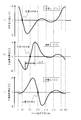
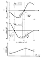
- the wave form diagram with respect to the rotor magnetic pole phase of a non-energized phase voltage is shown, (a) is an energizing mode (2), (b) is an energizing mode (3), and (c) is an explanatory diagram about the energizing mode (4).
- (A) is a waveform diagram with respect to time of the non-energized phase voltage
- (b) is a time chart of the energized mode. The timing for returning to the positioning energization mode will be described.
- (A) is a waveform diagram with respect to the rotor magnetic pole phase of the non-energized phase voltage in the energized mode (3)
- (b) is the rotor magnetic pole phase of the non-energized phase voltage in the energized mode (2).
- (C) is a waveform diagram with respect to time of the non-conduction phase voltage. It is a flowchart which shows the content of the normal direction switching process of electricity supply mode.
- (a) is a waveform diagram with respect to time of the non-energization phase voltage in the positioning energization mode
- (b) is a graph showing the ratio of each peak value to the first peak in (a). It is.
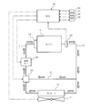
- FIG. 1 shows an example of a cooling system for cooling an engine.
- Cooling water as a refrigerant that has cooled the cylinder block, the cylinder head, and the like of the engine 10 is guided to the radiator 16 provided with the electric radiator fan 14 through the first cooling water passage 12.
- the cooling water guided to the radiator 16 exchanges heat with the outside air when passing through the radiator core to which the fins are attached, and the temperature thereof decreases. Then, the cooling water whose temperature has been lowered by passing through the radiator 16 is returned to the engine 10 via the second cooling water passage 18.
- first cooling water passage 12 and the second cooling water passage 18 are connected to each other via the bypass passage 20 so that the cooling water discharged from the engine 10 bypasses the radiator 16.
- An electric thermostat 22 that opens and closes the passage area of the bypass passage 20 in multiple stages or continuously from fully open to fully closed is arranged at the junction between the downstream end of the bypass passage 20 and the second coolant passage 18. It is installed.
- the electric control thermostat 22 is configured as an on-off valve that opens and closes the valve by utilizing the fact that the built-in wax is thermally expanded by a built-in heater that is driven according to the duty ratio of the PWM signal through a drive circuit, for example. can do. Therefore, the ratio of the cooling water passing through the radiator 16 can be changed by controlling the electric control thermostat 22 with the duty ratio.
- a mechanical water pump 24 that forcibly circulates cooling water between the engine 10 and the radiator 16 at a downstream end of the second cooling water passage 18 and an intermediate portion downstream of the electric control thermostat 22.
- the electric water pump 26 is each arrange
- the mechanical water pump 24 is attached so as to close the cooling water inlet of the engine 10 and is driven by, for example, a camshaft of the engine 10.
- the electric water pump 26 is driven by a brushless motor, which will be described later, which is a driving source different from the engine 10 so that the cooling performance can be exhibited or the heating function can be maintained even when the engine 10 is stopped by the idle stop function.
- a water temperature sensor 28 As a control system for controlling the driving of the radiator fan 14, the electric thermostat 22 and the electric water pump 26, a water temperature sensor 28 as a cooling water temperature detecting means for detecting the temperature of the cooling water discharged from the engine 10 (cooling water temperature).
- a vehicle speed sensor 30 for detecting the vehicle speed, a temperature sensor 32 for detecting the outside air temperature, a rotation speed sensor 34 for detecting the engine rotation speed, and a load sensor 36 for detecting the engine load are attached.
- the output signals of the water temperature sensor 28, the vehicle speed sensor 30, the temperature sensor 32, the rotational speed sensor 34, and the load sensor 36 are input to an engine control unit (hereinafter referred to as “ECU”) 38 having a built-in computer, and the ROM (The radiator fan 14, the electric thermostat 22 and the electric water pump 26 are controlled according to a control program stored in “Read Only Memory” or the like.
- ECU engine control unit
- the ECU 38 repeatedly determines whether or not a driving condition for driving the electric water pump 26 is satisfied, at least during the operation of the engine 10. When the ECU 38 determines that this drive condition is satisfied, it outputs a drive command signal to the electric water pump 26, while when it determines that the drive condition is not satisfied, the electric water pump A stop command signal for stopping or prohibiting the drive 26 is output.
- the driving condition of the electric water pump 26 is that the oil temperature of the engine 10 is equal to or higher than a predetermined temperature.
- a predetermined temperature As another driving condition, regarding the driving circuit or signal circuit of the electric water pump 26, for example, voltage is ensured, normality is diagnosed by overcurrent diagnosis / microcomputer diagnosis / relay diagnosis, or For example, the relay is turned on.
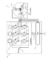
- FIG. 2 shows an example of a brushless motor that drives the electric water pump 26 and this control device.
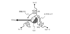
- the brushless motor 100 is a three-phase DC (Direct Current) brushless motor (three-phase synchronous motor), and a U-phase, V-phase, and W-phase three-phase windings 110u, 110v, and 110w are not illustrated.
- a rotor (permanent magnet rotor) 120 is rotatably provided in a space formed in the center portion of the stator.
- the U-phase winding 110u, the V-phase winding 110v, and the W-phase winding 110w are arranged in this order in the clockwise rotation direction of the rotor 120 with a coil phase difference of an electrical angle of 120 degrees. It shall be.
- the center line of the U-phase winding 110u is the reference axis
- the center line of the V-phase winding 110v is 120 deg in electrical angle with respect to the reference axis
- the center line of the W-phase winding 110w is electrical angle with respect to the reference axis. It shall be located at 240deg.
- a control device 200 of the brushless motor 100 as a control unit includes a drive circuit 210 and a controller 220 including a microcomputer.
- the motor control device 200 is not limited to the one disposed in the vicinity of the brushless motor 100.
- at least the controller 220 of the motor control device 200 may be formed integrally with the ECU 38 or another control unit.
- the drive circuit 210 includes a circuit in which switching elements 214a to 214f including antiparallel diodes 212a to 212f are connected in a three-phase bridge, and a power supply circuit 230.
- the switching elements 214a to 214f are, for example, IGBTs (Insulated Gate Bipolar Transistor) and other semiconductor elements used for power control.
- Control terminals (gate terminals) of the switching elements 214a to 214f are connected to the controller 220, and on / off of the switching elements 214a to 214f is controlled by a PWM operation by the controller 220 as described later.
- the controller 220 is configured to input a drive command signal from the ECU 38.
- the controller 220 includes a circuit that receives a drive command signal for the brushless motor 100 from the ECU 38, calculates an applied voltage that is an operation amount of the brushless motor 100, and generates a PWM signal based on the applied voltage. Further, the controller 220 sequentially switches a two-phase selection pattern (hereinafter referred to as “energization mode”) that applies a pulsed voltage (hereinafter referred to as “pulse voltage”) among the three phases according to a predetermined switching timing. It has a circuit to go.
- the controller 220 determines the operation of each of the switching elements 214a to 214f of the drive circuit 210 based on the PWM signal and the energization mode, and according to the determination, the six gate signals are transferred to the drive circuit. Output to 210.
- Controller 220 detects the predetermined switching timing as follows. That is, by applying a pulsed voltage (hereinafter referred to as “pulse voltage”) to the two phases, an induced voltage (hereinafter, referred to as a non-energized phase (open phase)) among the three phases of the brushless motor 100.
- the switching timing of the energization mode is detected by comparing the detected value of “pulse-induced voltage”) with a predetermined threshold value that is different for each energization mode.
- the pulse induced voltage is generated as a voltage corresponding to the position of the rotor 120 due to the saturation state of the magnetic circuit changing depending on the position of the rotor 120.
- the pulse-induced voltage is detected as the terminal voltage of the non-energized phase. Strictly speaking, this terminal voltage is a voltage between the ground GND and the terminal, but in the present embodiment, a neutral point voltage is separately detected, and a difference between the neutral point voltage and the GND-terminal voltage is calculated.
- the terminal voltages Vu, Vv, and Vw are obtained.
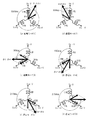
- FIG. 3 shows a voltage application state to each phase in each energization mode.
- the energization mode is composed of six energization modes (1) to (6) that are sequentially switched every electrical angle of 60 deg.
- the magnetic pole position) is set to 30 deg
- the angular position of the rotor 120 for switching from the energization mode (4) to the energization mode (5) is set to 90 deg
- the angle position of the rotor 120 for switching from the energization mode (6) to the energization mode (1) is set to 210 deg, and the rotor 120 for switching from the energization mode (1) to the energization mode (2) is set to 150 deg.
- the angular position of the rotor 120 that switches from the energization mode (2) to the energization mode (3) is set to 330 deg.
- the switching element 214a and the switching element 217d are turned on and all others are turned off, so that the voltage V is applied to the U phase, the voltage ⁇ V is applied to the V phase, A current is passed toward the V phase.
- the switching element 214a and the switching element 214f are turned on, and all others are turned off, so that the voltage V is applied to the U phase, the voltage ⁇ V is applied to the W phase, A current is passed toward the W phase.
- the switching element 217c and the switching element 214f are turned on, and all others are turned off, so that the voltage V is applied to the V phase, the voltage ⁇ V is applied to the W phase, A current is passed toward the W phase.
- the switching element 217b and the switching element 217c are turned on, and all others are turned off, so that the voltage V is applied to the V phase, the voltage ⁇ V is applied to the U phase, A current is passed toward the U phase.
- the switching element 217b and the switching element 217e are turned on, and all others are turned off, so that the voltage V is applied to the W phase, the voltage ⁇ V is applied to the U phase, A current is passed toward the U phase.
- the switching element 217e and the switching element 217d are turned on, and all others are turned off, so that the voltage V is applied to the W phase, the voltage ⁇ V is applied to the V phase, and from the W phase. A current is passed toward the V phase.
- the six energization modes (1) to (6) are energized for 120 deg every 180 deg by sequentially switching every 60 deg electrical angle by turning on / off the switching elements 214a to 214f.
- the energization method as shown in 3 is called a 120-degree energization method.
- the switching control of the energization mode is performed based on the induced voltage of the non-energized phase, it is a so-called position sensorless energization control, and among them, is performed based on the pulse induced voltage induced in the non-energized phase.
- This is “low-speed sensorless control”.
- the low speed sensorless control is energization control used in a low speed range when the motor rotation speed is divided into a low speed range and a high speed range.
- the high-speed sensorless control used in the high-speed range is a control for detecting an induced voltage (hereinafter referred to as “speed electromotive voltage”) generated by the rotation of the rotor 120 and switching the energization mode based on the speed electromotive voltage. Set the energization mode switching point based on the zero cross point of the voltage.
- speed electromotive force used in the high-speed sensorless control decreases the sensitivity of the speed electromotive force due to noise or the like when the motor rotation speed decreases.
- the high-speed sensorless control is performed in a rotational speed range that is equal to or higher than a predetermined motor rotational speed at which the switching point of the energization mode can be accurately detected based on the speed electromotive voltage, that is, in a high speed range.
- the low speed sensorless control can detect the pulse induced voltage according to the position of the rotor 120 without depending on the rotational speed of the rotor 120, the energization control by the high speed sensorless control is difficult. It is carried out in the rotational speed range, that is, in the low speed range.
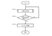
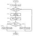
- FIG. 4 shows the control processing content of the brushless motor 100 that is started by the controller 220 in response to the output of the drive command signal from the ECU 38 and ends in response to the output of the stop command signal from the ECU 38.
- step 1001 (abbreviated as “S1001” in the figure, the same applies hereinafter), positioning control for positioning the rotor 120 at a predetermined position is performed in order to rotate the rotor 120 by sensorless control described later. Details of the positioning control process of the rotor 120 will be described later.
- step 1002 positioning completion determination is performed to determine whether or not the positioning control processing in step 1001 has been completed.
- the standard for determining the positioning completion is, for example, when the time during which the absolute value of the voltage generated in the non-energized phase is equal to or less than a predetermined value continues for a predetermined time, or after switching the positioning energization mode described later to a different energization mode.
- the predetermined time elapses, the swing of the rotor 120 centered on the predetermined position by the positioning control process is attenuated or attenuated to the extent that the sensorless control at step 1003 may be shifted. It is estimated that. If it is determined that the positioning control process has been completed, the process proceeds to step 1003 (Yes). On the other hand, if it is determined that the positioning control process has not been completed, the process returns to step 1001 (No).
- step 1003 sensorless control of the brushless motor 100 is performed. Specifically, first, the above-described low-speed sensorless control is performed, and when the rotational speed of the brushless motor 100 increases to reach a predetermined speed, the above-described high-speed sensorless control is performed.
- FIG. 5 shows details of the positioning control process of the rotor 120 in step 1001.
- a positioning energization mode is performed so as to position the rotor 120 at a predetermined position. That is, in any one of the energization modes (1) to (6) in FIG. 3, the energization is maintained by applying a voltage to two predetermined phases among the three phases, and the magnetic flux generated in the two phases causes one of the rotor 120 to The magnetic poles (for example, N poles) are attracted, and the rotor 120 rotates so that the phase of the magnetic poles matches the positioning angle set according to the energization mode.
- the magnetic poles for example, N poles
- the positioning angle set according to each energization mode is the phase of the combined magnetic flux that combines the magnetic flux generated by the excitation current of each phase.
- the positioning angle in each energization mode is 330 deg in the energization mode (1), 30 deg in the energization mode (2), 90 deg in the energization mode (3), and 150 deg in the energization mode (4).
- the energization mode (5) it is 210 deg
- in the energization mode (6) it is 270 deg.
- the direction in which the positioning angle changes when the energization mode is switched in ascending order is the forward direction
- the direction in which the positioning angle changes when the energization mode is switched in the descending order is the reverse direction.
- Switching in ascending order is referred to as “forward direction”
- switching the energization mode in descending order is referred to as “reverse direction”.
- the energization mode (3) is set to the positioning energization mode, the voltage V is applied to the V phase, and the voltage ⁇ V is applied to the W phase. A current is passed from W to the W phase, and the positioning angle is set to 90 deg.
- the U phase is a non-energized phase.
- the applied voltage V in each energization mode is a temperature at which the viscosity of the cooling water in the cooling system becomes the highest in order to enable rotation of the rotor 120 in the positioning control process under all temperature conditions using the electric water pump 26.
- a voltage at which the rotor 120 can operate against friction is set.
- the applied voltage V may be set according to the temperature, for example, set lower as the temperature such as the water temperature detected by the water temperature sensor 28 or the outside air temperature detected by the temperature sensor 32 becomes higher.
- the pulse induced voltage generated in the non-energized phase is substantially 0 (see black circles in the figure). Then, by storing such a voltage waveform in advance, the position of the rotor 120 can also be specified based on the stored voltage waveform and the pulse induced voltage generated in the non-energized phase.
- a speed electromotive voltage corresponding to the rotational speed of the rotor 120 that causes the swing of the magnetic pole phase to increase or decrease with respect to the positioning angle is superimposed on the pulse induced voltage generated in the non-energized phase.
- the controller 220 does not identify the magnetic pole position of the rotor 120 with reference to the voltage waveform of FIG.
- the voltage waveform in FIG. 8 is used as the voltage generated in the non-conduction phase.
- step 2002 it is determined whether or not energization mode switching control for switching the positioning energization mode can be started.
- the positioning energization mode is switched for the following reasons. That is, as a result of the execution of the positioning energization mode in step 2001, the rotor 120 that has started to rotate as shown in FIG. 7 oscillates so that the phase of its magnetic pole (for example, N pole) increases or decreases with respect to the positioning angle.
- the inertia segment of inertia
- the start of the sensorless control in the above-described step 1003 is delayed, and the start-up response of the electric water pump 26 and the like may be reduced.
- the standard for starting the energization mode switching control is, for example, step In FIG. 8 (b), for example, a predetermined time has elapsed since the execution of the positioning energization mode in 2001, the non-energization is performed as the magnetic pole phase of the rotor 120 increases or decreases across the positioning angle due to the swing of the rotor 120. It is estimated that the magnetic pole phase of the rotor 120 is within a range where the phase voltage also increases or decreases. For example, when the positioning energization mode is the energization mode (3), it is estimated that the magnetic pole phase of the rotor 120 is within the range of ⁇ in FIG.
- the positioning energization mode is switched to a different energization mode, for example, the absolute value of the voltage generated in the non-energization phase exceeds a predetermined voltage, and “brake” is performed. It is a reference for starting the energization mode switching control that the swinging of the rotor 120 is not difficult to attenuate by acting.
- step 2002 If it is determined in step 2002 that energization mode switching control can be started, the process proceeds to step 2003 (Yes), and if it is determined that energization mode switching control cannot be started, positioning control is performed. The process is terminated (No).
- the time change rate ⁇ of the induced voltage generated in the non-energized phase (for example, the U phase) is calculated.
- the controller 220 includes detection means for detecting a non-energized phase voltage every minute time ⁇ t, and among the non-energized phase voltages detected by the detection means, the voltage V1 detected this time and the previous time are detected.
- a subtraction value (V1-V2) is obtained from the detected voltage V2, and the time change rate ⁇ is calculated by dividing this subtraction value by the minute time ⁇ t.
- the time change rate ⁇ may be a subtraction value (V1 ⁇ V2).
- the time change rate ⁇ is calculated by superimposing a speed electromotive voltage corresponding to the rotational speed of the rotor 120 on the voltage of the non-conducting phase so that the magnetic pole phase of the rotor 120 is derived from the voltage waveform of FIG. This is because it is only necessary to estimate whether the rotor 120 is rotating in the forward direction or the reverse direction.
- the energization mode switching flag Fmod is set.
- the energization mode switching flag Fmod is a flag indicating either forward switching for switching one energization mode in the forward direction or reverse switching for switching one energization mode in the reverse direction with respect to the positioning energization mode. .
- the positioning energization mode is the energization mode (3)
- Whether the switching flag Fmod of the energization mode that is, whether the forward direction switching or the reverse direction switching is set depends on whether or not the change rate ⁇ calculated in step 2003 is less than 0.
- Fmod 0 is set to perform reverse direction switching.
- Fmod Set to 1.
- Step 2006 the energization mode is switched in the reverse direction. Details of the reverse switching of the energization mode will be described later.
- step 2007, the energization mode is switched in the forward direction. Details of forward switching of the energization mode will be described later.
- FIG. 11 shows the details of the reverse switching process of the energization mode in step 2006.
- step 3001 similarly to step 2003, the time change rate ⁇ ′ of the minute time ⁇ t of the voltage generated in the non-energized phase (for example, the U phase) is calculated.
- the reverse direction switching execution flag Fcw of the energization mode is set.
- the reverse direction switching execution flag Fcw is a flag indicating whether or not to perform reverse direction switching of the energization mode.
- Fcw 0, it indicates that reverse switching is not performed.
- the reverse direction switching flag Fcw indicating whether or not to perform the reverse direction switching is further set based on the rotation direction of the rotor 120. This is to confirm again that it is the forward direction and to prevent the “brake” on the rotor 120 from accelerating the rotor 120.
- the forward direction switching is performed.
- Set Fcw 1 for implementation.
- step 3003 it is determined whether the reverse direction switching execution flag Fcw is 0 or 1.
- Fcw 0, since the reverse switching of the energization mode is not performed, the forward switching process of the energization mode is terminated in order to determine whether or not the positioning control process in step 1002 has been completed.
- step 3004 the energization mode is switched from the positioning energization mode to the reverse direction.
- the positioning energization mode is the energization mode (3) as in this embodiment, the mode is switched to the energization mode (2).
- step 3005 it is determined whether or not a predetermined time has elapsed since the energization mode was switched in the reverse direction in step 3004.
- the predetermined time is a time during which a reflux current flowing in the non-energized phase is generated with the switching of the energization mode.
- energization mode (3) which is a positioning energization mode
- energization occurs when the rotor 120 rotates in the positive direction and the voltage generated in the non-energized phase (U phase) changes from point A to point B.
- the mode is switched to the mode (2) and the rotor 120 is rotated in the positive direction and the voltage generated in the non-energized phase (V phase) is changed from the point B ′ to the point C ′, the process will be described later in step 3008.
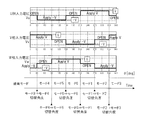
- the time change of the voltage generated in the non-energization phase is as shown in FIG.
- the voltage of the phase is stuck to the GND (ground) voltage. Therefore, at this time ⁇ , whether the rotor 120 is rotating in the forward direction or the reverse direction even if the time change rate is calculated for the voltage of the non-energized phase as in Step 3006 described later. Cannot be estimated.
- step 3005 If it is determined in step 3005 that the predetermined time has elapsed, the process proceeds to step 3006 (Yes). On the other hand, if it is determined that the predetermined time has not elapsed, this step is repeated (No). ). If priority is given to reducing the processing load by the controller 220, step 3005 need not be performed. The same applies to the forward direction switching process described later.
- step 3006 the time change rate ⁇ of the voltage generated in the non-energized phase (V phase) is calculated as in step 2003.
- step 3007 it is determined whether or not the time change rate ⁇ of the voltage generated in the non-energized phase (V phase) is less than 0 in order to detect the timing for returning the energization mode to the positioning energization mode.
- the reason why the timing for returning to the positioning energization mode is detected by the time change rate ⁇ of the voltage generated in the non-energization phase will be described.
- the rotor 120 rotates in the positive direction, and the voltage generated in the non-energized phase (U phase) changes from the D point to the E point.
- the rotor 120 rotates in the positive direction due to the inertia even after switching, so that the voltage generated in the non-energized phase (V phase) is directed from point E ′ to point F ′. Change.
- the positioning angle in the energization mode (2) is 30 deg and the reverse torque is applied to the rotor 120 and the "brake" is acting, the forward rotation of the rotor 120 is finally Stop and start turning in the opposite direction.
- the voltage of the non-energized phase (V phase) rises from the point E ′ to the point F ′, for example, but then decreases toward the point E ′. That is, as shown in FIG. 14C, the time change rate of the voltage of the non-conduction phase (V phase) is reversed between plus and minus at the F ′ point.
- the energization mode (2) When the energization mode (2) is maintained when the rotor 120 starts to rotate in the reverse direction, the swing of the rotor 120 is increased and the time change rate changes to less than 0. The energization mode (2) is returned to the energization mode (3) which is the positioning energization mode.
- Step 3007 when it is determined that the time change rate ⁇ of the voltage generated in the non-energized phase (V phase) is less than 0, the process proceeds to Step 3008 (Yes). On the other hand, when it is determined that the time change rate ⁇ of the voltage generated in the non-energized phase (V phase) is 0 or more, the process returns to Step 3006 (No).
- step 3008 the positioning energization mode is performed.
- the energization mode (2) is returned to the positioning energization mode, the voltage generated in the non-energization phase (U phase) as shown in FIG. 13 as in the case where the positioning energization mode is switched to the energization mode (2) in step 3004. Is caused to stick to the GND voltage due to reflux.
- step 1002 performed after this step, it is determined whether or not the positioning control process is completed based on the voltage of the non-energized phase itself. Therefore, when step 1002 is executed, as in step 3005, the non-energized phase voltage may not be detected until the reflux time elapses after the positioning energization mode is performed in this step.
- the non-energized phase voltage may be detected after detecting an edge when the non-energized phase voltage rises to the GND voltage and then rises again.
- FIG. 15 shows details of the forward switching process of the energization mode in step 2007.
- the forward direction switching process is the same as the backward direction switching process of FIG. 11 except that the forward direction torque is generated with respect to the rotor 120 rotating in the reverse direction. Simplified or omitted.
- step 4001 as in step 2003, the time change rate ⁇ ′ in the minute time ⁇ t of the voltage generated in the non-energized phase (for example, U phase) is calculated.
- the forward direction switching execution flag Fccw of the energization mode is set.
- the forward direction switching execution flag Fccw is a flag indicating whether or not to perform forward direction switching of the energization mode.
- Fccw 0 is set so as to stop the forward direction switching.
- step 4003 it is determined whether the forward direction switching execution flag Fccw is 0 or 1.
- Fccw 0, since the forward switching of the energization mode is not performed, the forward switching process of the energization mode is terminated in order to determine whether or not the positioning control process in Step 1002 has been completed.
- Fccw 1
- the routine proceeds to step 4004 to switch the energization mode in the forward direction.
- step 4004 the energization mode is switched from the positioning energization mode to the positive direction.
- the positioning energization mode is the energization mode (3) as in this embodiment, the mode is switched to the energization mode (4).
- step 4005 it is determined whether or not a predetermined time has elapsed since the energization mode was switched in the reverse direction in step 4004.
- the predetermined time is a time during which a reflux current flowing in the non-energized phase is generated with the switching of the energization mode. If it is determined that the predetermined time has elapsed, the process proceeds to step 4006 (Yes). On the other hand, if it is determined that the predetermined time has not elapsed, this step is repeated (No).
- step 4006 as in step 2003, the time change rate ⁇ of the voltage generated in the non-energized phase (V phase) is calculated.
- step 4007 it is determined whether or not the time change rate ⁇ of the voltage generated in the non-energized phase (V phase) is less than 0 in order to detect the timing for returning the energized mode to the positioning energized mode.
- the process proceeds to Step 4008 (Yes).
- the process returns to step 4006 (No).
- step 4008 the positioning energization mode is performed.
- a “brake” can be applied to the rotor 120 that rotates in the positioning energization mode by generating torque in the direction opposite to the rotation direction. For this reason, even if the rotor of the electric water pump 26 driven by the brushless motor 100 and the inertia of the rotor 120 itself are increased, the swing of the rotor 120 with respect to the positioning angle in the positioning energization mode is not easily attenuated. Therefore, since the time required for positioning the rotor 120 can be shortened from about 0.8 seconds to 0.115 seconds, for example, the sensorless control in Step 1003 can be started quickly, and the start response of the electric water pump 26 Improves.
- the positioning energization mode is switched to the forward direction or the reverse direction, and the “brake” is applied to the rotating rotor 120. Also good. This is because when the water temperature decreases and the friction of the electric water pump 26 increases due to the temperature dependency of the viscosity of the cooling water in the cooling system, this friction serves as a “brake” and the oscillation of the rotor 120 is attenuated. This is because it becomes easier.
- the above-mentioned predetermined case is, for example, the upper limit value of the water temperature that becomes the viscosity of the cooling water that does not affect the start-up response of the electric water pump 26 without applying the “brake” by switching the positioning energization mode.
- the measured value of the water temperature is less than or equal to this upper limit value.
- the predetermined case described above assumes that the voltage of the non-energized phase is within the range of ⁇ in FIG. 8B, for example, at the zero cross point, etc.
- the time change rate may be a predetermined rate or less. Since the time change rate of the non-energized phase voltage decreases as the viscosity of the cooling water increases even when the magnetic pole phase of the rotor is the same, the above-mentioned predetermined rate affects the start-up response of the electric water pump 26. This is the upper limit of the rate of change over time when the viscosity of the cooling water is not given.
- the positioning energization mode is switched to the reverse direction or the forward direction (steps 3004 and 4004), and torque is generated in the direction opposite to the rotation direction on the rotating rotor 120 to apply the “brake”.
- the size of the “brake” may be gradually reduced according to the time elapsed since the execution of the positioning energization mode in step 2001.
- the energization mode (3) which is the positioning energization mode
- the energization mode ( 2) or the motor applied voltage V in the energization mode (4) is decreased.
- the torque generated in the direction opposite to the rotation direction of the rotor 120 can be reduced and the size of the “brake” can be gradually reduced. Reduce the likelihood of attenuation.
- the size of the “brake” is gradually decreased according to the amplitude of the voltage of the non-energized phase in the positioning energization mode. Also good.
- the non-energized phase voltage in the positioning energization mode is a peak voltage that gradually decreases as the oscillation of the rotor 120 attenuates (open circles in the figure). Are sequentially detected after it is determined in step 2002 that energization mode switching control can be started.
- the peak voltage ratio obtained by dividing each peak voltage V1, V2, V3, V4, V5, V6... By the peak voltage V1 detected first and making it an absolute value.
- step 3004 or step 4004 is first performed after the calculation of the peak voltage ratio, a voltage obtained by multiplying the motor applied voltage V (or -V) by the latest peak voltage ratio is applied, and the energization mode (2) Or energization mode (4) is implemented. Even in this case, the torque generated in the direction opposite to the rotation direction of the rotor 120 can be reduced and the size of the “brake” can be gradually reduced. Thus, it is possible to prevent the time required for positioning from being shortened.
- the size of the “brake” can be gradually reduced not only according to the time and the voltage of the non-energized phase in the positioning energization mode, but also according to the water temperature and the rate of time change described above. is there. For example, the size of the “brake” is decreased as the water temperature increases, while the size of the “brake” is gradually increased as the water temperature decreases. Further, for example, the size of the “brake” is gradually decreased as the time change rate increases, and the magnitude of the “brake” is gradually increased as the time change rate decreases.
- the brushless motor 100 is not only applied to the power source of the electric water pump 26, but also, for example, a power source of an oil pump that provides a lubricating cooling function / hydraulic pressure to an engine, a transmission, etc.
- the present invention can be applied to various uses such as an electric actuator for operating various mechanical parts.
- a brushless motor control device for energizing two phases of the plurality of phases of the brushless motor and positioning the rotor at a predetermined position when receiving a start command for the brushless motor,
- the positioning energization mode to be energized is temporarily switched to the energization mode to energize another two phases different from the two phases, the positioning energization mode is executed after a predetermined time has elapsed when the positioning energization mode is resumed.
- the time change rate of the non-energized phase voltage can be calculated with high accuracy.
- the energization mode for energizing the other two phases is positive or negative in the rate of change of the voltage generated in the non-energization phase.
- the switching to the positioning energization mode is performed again according to the above or according to the positive / negative of the slope of the voltage generated in the non-energization phase, or (a) or (b) The control apparatus of the brushless motor as described in any one of these.
- the rotor is in the forward or reverse direction. It can be estimated to which direction it is rotating.
- the positioning energization mode energizes the two phases with a voltage that allows the rotor to rotate according to the temperature of the medium pumped by the electric pump.
- the brushless motor control device according to any one of claims 1 to 3, or (a) to (e). In this way, in the positioning control, there is an advantage that the rotor can be rotated against the friction with the medium pumped by the electric pump, and wasteful power is not consumed.
- the energization mode for energizing the other two phases changes the voltage energized to the other two phases according to the viscosity of the medium pumped by the electric pump.
- the brushless motor control device according to any one of claims 1 to 3, or (a) to (f). Due to the temperature dependence of the viscosity of the medium pumped by the electric pump, if the temperature of the medium decreases and the friction of the electric water pump increases, this friction can be used as a “brake” and the oscillation of the rotor tends to attenuate. Become. For this reason, useless electric power is not consumed when the “brake” is not required.
Landscapes
- Engineering & Computer Science (AREA)
- Power Engineering (AREA)
- Control Of Motors That Do Not Use Commutators (AREA)
Abstract
Description
本実施形態のように、位置決め通電モードが通電モード(3)である場合、通電モード(4)へ切り替える。
Claims (14)
- ブラシレスモータの起動指令を受けた場合に、前記ブラシレスモータの所定相に対する通電を保持してロータを所定位置に位置決めするブラシレスモータの制御装置であって、
前記所定相に対して通電を保持する位置決め通電モードを、非通電相に生じる電圧に基づいて、前記所定相と異なる組み合わせの相に通電する他の通電モードへ一時的に切り替えることを特徴とするブラシレスモータの制御装置。 - 前記他の通電モードは、前記位置決め通電モードにより回動する前記ロータに対し、回動方向と反対方向にトルクを発生させることを特徴とする請求項1に記載のブラシレスモータの制御装置。
- 前記位置決め通電モードは、前記非通電相に生じる電圧の変化に応じて、前記他の通電モードへ一時的に切り替えられることを特徴とする請求項1に記載のブラシレスモータの制御装置。
- 前記位置決め通電モードを、前記非通電相に生じる電圧に基づいて、前記他の通電モードへ一時的に切り替えた場合、前記位置決め通電モードを再開するときには所定時間経過してから前記位置決め通電モードを実施することを特徴とする請求項1に記載のブラシレスモータの制御装置。
- 前記位置決め通電モードは、前記非通電相に生じる電圧の変化率における正負に応じて、前記他の通電モードへ一時的に切り替えられることを特徴とする請求項1に記載のブラシレスモータの制御装置。
- 前記位置決め通電モードを前記他の通電モードへ一時的に切り替えた場合、前記他の通電モードは、前記非通電相に生じる電圧の変化率における正負に応じて、前記位置決め通電モードに再び切り替えられることを特徴とする請求項5に記載のブラシレスモータの制御装置。
- 前記位置決め通電モードから前記他の通電モードに切り替える場合の前記非通電相に生じる電圧の変化率は、前記他の通電モードから前記位置決め通電モードに切り替える場合の前記非通電相に生じる電圧の変化率に対して、正負が逆になることを特徴とする請求項1に記載のブラシレスモータの制御装置。
- 前記ブラシレスモータが電動ポンプを駆動する場合、前記位置決め通電モードでの通電電圧は、前記電動ポンプにより圧送される媒体の温度に応じて前記ロータが回転できる電圧であることを特徴とする請求項1に記載のブラシレスモータの制御装置。
- 前記ブラシレスモータが電動ポンプを駆動する場合、前記他の通電モードでの通電電圧は、前記電動ポンプにより圧送される媒体の粘度に応じて変更されることを特徴とする請求項1に記載のブラシレスモータの制御装置。
- 前記他の通電モードでの通電電圧は、前記媒体の温度に応じて変更されることを特徴とする請求項9に記載のブラシレスモータの制御装置。
- 前記他の通電モードでの通電電圧は、前記非通電相に生じる電圧の変化率に応じて変更されることを特徴とする請求項9に記載のブラシレスモータの制御装置。
- 前記他の通電モードでの通電電圧を、前記位置決め通電モードにより前記所定相へ通電を開始してからの経過時間に応じて、徐々に減少させることを特徴とする請求項1に記載のブラシレスモータの制御装置。
- 前記他の通電モードでの通電電圧を、前記位置決め通電モードにおける前記非通電相の電圧の振幅に応じて、徐々に減少させることを特徴とする請求項1に記載のブラシレスモータの制御装置。
- ブラシレスモータのコントロールユニットが、該ブラシレスモータの起動指令を受けた場合に、該ブラシレスモータの所定相に対する通電を保持し、非通電相に生じる電圧に基づいて、前記所定相と異なる組み合わせの相へ一時的に通電を切り替えるブラシレスモータの制御方法。
Priority Applications (3)
| Application Number | Priority Date | Filing Date | Title |
|---|---|---|---|
| US14/427,413 US20150249410A1 (en) | 2013-04-23 | 2014-03-13 | Control Device and Control Method for Brushless Motor |
| CN201480002209.XA CN104584418A (zh) | 2013-04-23 | 2014-03-13 | 无刷电动机的控制装置以及控制方法 |
| DE112014002090.7T DE112014002090T5 (de) | 2013-04-23 | 2014-03-13 | Steuerungsvorrichtung und Steuerungsverfahren für einen bürstenlosen Motor |
Applications Claiming Priority (2)
| Application Number | Priority Date | Filing Date | Title |
|---|---|---|---|
| JP2013-090687 | 2013-04-23 | ||
| JP2013090687A JP6058460B2 (ja) | 2013-04-23 | 2013-04-23 | ブラシレスモータの制御装置 |
Publications (1)
| Publication Number | Publication Date |
|---|---|
| WO2014174930A1 true WO2014174930A1 (ja) | 2014-10-30 |
Family
ID=51791515
Family Applications (1)
| Application Number | Title | Priority Date | Filing Date |
|---|---|---|---|
| PCT/JP2014/056790 Ceased WO2014174930A1 (ja) | 2013-04-23 | 2014-03-13 | ブラシレスモータの制御装置及び制御方法 |
Country Status (5)
| Country | Link |
|---|---|
| US (1) | US20150249410A1 (ja) |
| JP (1) | JP6058460B2 (ja) |
| CN (1) | CN104584418A (ja) |
| DE (1) | DE112014002090T5 (ja) |
| WO (1) | WO2014174930A1 (ja) |
Families Citing this family (1)
| Publication number | Priority date | Publication date | Assignee | Title |
|---|---|---|---|---|
| US10473193B2 (en) * | 2015-09-04 | 2019-11-12 | Mitsubishi Heavy Industries Compressor Corporation | Control method for variable speed electric motor system and control device for variable speed electric motor system |
Citations (3)
| Publication number | Priority date | Publication date | Assignee | Title |
|---|---|---|---|---|
| JPH11341872A (ja) * | 1998-05-28 | 1999-12-10 | Ntn Corp | センサレス同期サーボモータの起動方法および制御装置 |
| JP2012196064A (ja) * | 2011-03-17 | 2012-10-11 | Hitachi Automotive Systems Ltd | 同期電動機の駆動装置 |
| JP2012253971A (ja) * | 2011-06-06 | 2012-12-20 | Aisin Seiki Co Ltd | モータ制御装置 |
Family Cites Families (10)
| Publication number | Priority date | Publication date | Assignee | Title |
|---|---|---|---|---|
| JPS6052660B2 (ja) * | 1979-06-04 | 1985-11-20 | 松下電器産業株式会社 | 回転速度信号検出器 |
| US5068582A (en) * | 1990-05-29 | 1991-11-26 | A. O. Smith Corporation | Brushless pulsed D.C. motor |
| IT1253596B (it) * | 1991-10-31 | 1995-08-22 | Sgs Thomson Microelectronics | Sistema di avviamento per un motore brushless multifase, privo di sensori di posizione del rotore. |
| US5796194A (en) * | 1996-07-15 | 1998-08-18 | General Electric Company | Quadrature axis winding for sensorless rotor angular position control of single phase permanent magnet motor |
| US6534936B2 (en) * | 2000-04-28 | 2003-03-18 | Western Digital Technologies, Inc. | Disk drive employing method of spinning up spindle motor including detecting BEMF polarity change for selecting initial commutation state |
| US7514887B2 (en) * | 2003-10-24 | 2009-04-07 | A. O. Smith Corporation | Electrical machine and method of controlling the same |
| US7202623B2 (en) * | 2004-03-30 | 2007-04-10 | Delta Electronics, Inc. | Startup procedure for sensorless brushless DC motor |
| US7573217B2 (en) * | 2005-05-31 | 2009-08-11 | Regal-Beloit Corporation | Methods and systems for automatic rotation direction determination of electronically commutated motor |
| WO2008149638A1 (ja) * | 2007-06-05 | 2008-12-11 | Edwards Japan Limited | ブラシレスモータ |
| TWI342104B (en) * | 2008-01-15 | 2011-05-11 | Feeling Technology Corp | Control apparatus for starting a direct current brushless motor and method thereof |
-
2013
- 2013-04-23 JP JP2013090687A patent/JP6058460B2/ja active Active
-
2014
- 2014-03-13 US US14/427,413 patent/US20150249410A1/en not_active Abandoned
- 2014-03-13 WO PCT/JP2014/056790 patent/WO2014174930A1/ja not_active Ceased
- 2014-03-13 DE DE112014002090.7T patent/DE112014002090T5/de not_active Withdrawn
- 2014-03-13 CN CN201480002209.XA patent/CN104584418A/zh active Pending
Patent Citations (3)
| Publication number | Priority date | Publication date | Assignee | Title |
|---|---|---|---|---|
| JPH11341872A (ja) * | 1998-05-28 | 1999-12-10 | Ntn Corp | センサレス同期サーボモータの起動方法および制御装置 |
| JP2012196064A (ja) * | 2011-03-17 | 2012-10-11 | Hitachi Automotive Systems Ltd | 同期電動機の駆動装置 |
| JP2012253971A (ja) * | 2011-06-06 | 2012-12-20 | Aisin Seiki Co Ltd | モータ制御装置 |
Also Published As
| Publication number | Publication date |
|---|---|
| DE112014002090T5 (de) | 2016-08-04 |
| CN104584418A (zh) | 2015-04-29 |
| JP2014217118A (ja) | 2014-11-17 |
| JP6058460B2 (ja) | 2017-01-11 |
| US20150249410A1 (en) | 2015-09-03 |
Similar Documents
| Publication | Publication Date | Title |
|---|---|---|
| JP6170455B2 (ja) | ブラシレスモータの制御装置及び制御方法 | |
| JP5952502B2 (ja) | 3相ブラシレスモータの駆動装置 | |
| US10381965B2 (en) | Drive device and method for three-phase brushless motor | |
| JP5970227B2 (ja) | 同期電動機の駆動システム | |
| US8231356B2 (en) | Control system and control method for electric water pump | |
| US10749453B1 (en) | Drive device and drive method of brushless motor | |
| US10447182B2 (en) | Control device and method for brushless motor | |
| JP2010045941A (ja) | モータ制御回路,車両用ファン駆動装置及びモータ制御方法 | |
| JP5561792B2 (ja) | ブラシレスモータの駆動装置 | |
| US20130002177A1 (en) | Sensorless control unit for brushless dc motor | |
| JP6058460B2 (ja) | ブラシレスモータの制御装置 | |
| JP5653264B2 (ja) | 同期電動機の駆動装置 | |
| JP2012050283A (ja) | ブラシレスモータの制御装置 | |
| JP5416067B2 (ja) | 車両用電動式ポンプの制御装置 | |
| JP6297868B2 (ja) | ブラシレスモータの制御装置及び制御方法 | |
| JP2013183550A (ja) | ブラシレスモータの駆動装置 | |
| JP5968738B2 (ja) | ブラシレスモータの制御装置 | |
| JP7356599B2 (ja) | ブラシレスモータの制御装置及び制御方法 | |
| JP6214983B2 (ja) | ブラシレスモータの制御装置 | |
| CN113557660A (zh) | 无传感器整流方法 | |
| KR20100075064A (ko) | Bldc 모터의 속도 제어방법 | |
| JP4900366B2 (ja) | 自律型インバータ駆動油圧ユニットの昇温制御方法および自律型インバータ駆動油圧ユニットの昇温制御装置 |
Legal Events
| Date | Code | Title | Description |
|---|---|---|---|
| DPE2 | Request for preliminary examination filed before expiration of 19th month from priority date (pct application filed from 20040101) | ||
| 121 | Ep: the epo has been informed by wipo that ep was designated in this application |
Ref document number: 14787574 Country of ref document: EP Kind code of ref document: A1 |
|
| WWE | Wipo information: entry into national phase |
Ref document number: 14427413 Country of ref document: US |
|
| WWE | Wipo information: entry into national phase |
Ref document number: 1120140020907 Country of ref document: DE Ref document number: 112014002090 Country of ref document: DE |
|
| 122 | Ep: pct application non-entry in european phase |
Ref document number: 14787574 Country of ref document: EP Kind code of ref document: A1 |