WO2014174683A1 - ブルドーザ - Google Patents
ブルドーザ Download PDFInfo
- Publication number
- WO2014174683A1 WO2014174683A1 PCT/JP2013/062476 JP2013062476W WO2014174683A1 WO 2014174683 A1 WO2014174683 A1 WO 2014174683A1 JP 2013062476 W JP2013062476 W JP 2013062476W WO 2014174683 A1 WO2014174683 A1 WO 2014174683A1
- Authority
- WO
- WIPO (PCT)
- Prior art keywords
- exhaust treatment
- treatment device
- engine
- connection pipe
- injector
- Prior art date
- Legal status (The legal status is an assumption and is not a legal conclusion. Google has not performed a legal analysis and makes no representation as to the accuracy of the status listed.)
- Ceased
Links
Images




Classifications
-
- E—FIXED CONSTRUCTIONS
- E02—HYDRAULIC ENGINEERING; FOUNDATIONS; SOIL SHIFTING
- E02F—DREDGING; SOIL-SHIFTING
- E02F3/00—Dredgers; Soil-shifting machines
- E02F3/04—Dredgers; Soil-shifting machines mechanically-driven
- E02F3/76—Graders, bulldozers, or the like with scraper plates or ploughshare-like elements; Levelling scarifying devices
- E02F3/7622—Scraper equipment with the scraper blade mounted on a frame to be hitched to the tractor by bars, arms, chains or the like, the frame having no ground supporting means of its own, e.g. drag scrapers
- E02F3/7631—Scraper equipment with the scraper blade mounted on a frame to be hitched to the tractor by bars, arms, chains or the like, the frame having no ground supporting means of its own, e.g. drag scrapers with the scraper blade adjustable relative to the frame about a horizontal axis
-
- E—FIXED CONSTRUCTIONS
- E02—HYDRAULIC ENGINEERING; FOUNDATIONS; SOIL SHIFTING
- E02F—DREDGING; SOIL-SHIFTING
- E02F9/00—Component parts of dredgers or soil-shifting machines, not restricted to one of the kinds covered by groups E02F3/00 - E02F7/00
- E02F9/20—Drives; Control devices
-
- B—PERFORMING OPERATIONS; TRANSPORTING
- B60—VEHICLES IN GENERAL
- B60K—ARRANGEMENT OR MOUNTING OF PROPULSION UNITS OR OF TRANSMISSIONS IN VEHICLES; ARRANGEMENT OR MOUNTING OF PLURAL DIVERSE PRIME-MOVERS IN VEHICLES; AUXILIARY DRIVES FOR VEHICLES; INSTRUMENTATION OR DASHBOARDS FOR VEHICLES; ARRANGEMENTS IN CONNECTION WITH COOLING, AIR INTAKE, GAS EXHAUST OR FUEL SUPPLY OF PROPULSION UNITS IN VEHICLES
- B60K13/00—Arrangement in connection with combustion air intake or gas exhaust of propulsion units
- B60K13/04—Arrangement in connection with combustion air intake or gas exhaust of propulsion units concerning exhaust
-
- E—FIXED CONSTRUCTIONS
- E02—HYDRAULIC ENGINEERING; FOUNDATIONS; SOIL SHIFTING
- E02F—DREDGING; SOIL-SHIFTING
- E02F3/00—Dredgers; Soil-shifting machines
- E02F3/04—Dredgers; Soil-shifting machines mechanically-driven
- E02F3/76—Graders, bulldozers, or the like with scraper plates or ploughshare-like elements; Levelling scarifying devices
- E02F3/80—Component parts
- E02F3/815—Blades; Levelling or scarifying tools
-
- E—FIXED CONSTRUCTIONS
- E02—HYDRAULIC ENGINEERING; FOUNDATIONS; SOIL SHIFTING
- E02F—DREDGING; SOIL-SHIFTING
- E02F9/00—Component parts of dredgers or soil-shifting machines, not restricted to one of the kinds covered by groups E02F3/00 - E02F7/00
- E02F9/08—Superstructures; Supports for superstructures
- E02F9/0858—Arrangement of component parts installed on superstructures not otherwise provided for, e.g. electric components, fenders, air-conditioning units
- E02F9/0866—Engine compartment, e.g. heat exchangers, exhaust filters, cooling devices, silencers, mufflers, position of hydraulic pumps in the engine compartment
-
- E—FIXED CONSTRUCTIONS
- E02—HYDRAULIC ENGINEERING; FOUNDATIONS; SOIL SHIFTING
- E02F—DREDGING; SOIL-SHIFTING
- E02F9/00—Component parts of dredgers or soil-shifting machines, not restricted to one of the kinds covered by groups E02F3/00 - E02F7/00
- E02F9/08—Superstructures; Supports for superstructures
- E02F9/0858—Arrangement of component parts installed on superstructures not otherwise provided for, e.g. electric components, fenders, air-conditioning units
- E02F9/0891—Lids or bonnets or doors or details thereof
-
- F—MECHANICAL ENGINEERING; LIGHTING; HEATING; WEAPONS; BLASTING
- F01—MACHINES OR ENGINES IN GENERAL; ENGINE PLANTS IN GENERAL; STEAM ENGINES
- F01N—GAS-FLOW SILENCERS OR EXHAUST APPARATUS FOR MACHINES OR ENGINES IN GENERAL; GAS-FLOW SILENCERS OR EXHAUST APPARATUS FOR INTERNAL-COMBUSTION ENGINES
- F01N13/00—Exhaust or silencing apparatus characterised by constructional features
- F01N13/009—Exhaust or silencing apparatus characterised by constructional features having two or more separate purifying devices arranged in series
-
- F—MECHANICAL ENGINEERING; LIGHTING; HEATING; WEAPONS; BLASTING
- F01—MACHINES OR ENGINES IN GENERAL; ENGINE PLANTS IN GENERAL; STEAM ENGINES
- F01N—GAS-FLOW SILENCERS OR EXHAUST APPARATUS FOR MACHINES OR ENGINES IN GENERAL; GAS-FLOW SILENCERS OR EXHAUST APPARATUS FOR INTERNAL-COMBUSTION ENGINES
- F01N13/00—Exhaust or silencing apparatus characterised by constructional features
- F01N13/18—Construction facilitating manufacture, assembly, or disassembly
-
- F—MECHANICAL ENGINEERING; LIGHTING; HEATING; WEAPONS; BLASTING
- F01—MACHINES OR ENGINES IN GENERAL; ENGINE PLANTS IN GENERAL; STEAM ENGINES
- F01N—GAS-FLOW SILENCERS OR EXHAUST APPARATUS FOR MACHINES OR ENGINES IN GENERAL; GAS-FLOW SILENCERS OR EXHAUST APPARATUS FOR INTERNAL-COMBUSTION ENGINES
- F01N13/00—Exhaust or silencing apparatus characterised by constructional features
- F01N13/18—Construction facilitating manufacture, assembly, or disassembly
- F01N13/1805—Fixing exhaust manifolds, exhaust pipes or pipe sections to each other, to engine or to vehicle body
-
- F—MECHANICAL ENGINEERING; LIGHTING; HEATING; WEAPONS; BLASTING
- F01—MACHINES OR ENGINES IN GENERAL; ENGINE PLANTS IN GENERAL; STEAM ENGINES
- F01N—GAS-FLOW SILENCERS OR EXHAUST APPARATUS FOR MACHINES OR ENGINES IN GENERAL; GAS-FLOW SILENCERS OR EXHAUST APPARATUS FOR INTERNAL-COMBUSTION ENGINES
- F01N3/00—Exhaust or silencing apparatus having means for purifying, rendering innocuous, or otherwise treating exhaust
- F01N3/08—Exhaust or silencing apparatus having means for purifying, rendering innocuous, or otherwise treating exhaust for rendering innocuous
- F01N3/10—Exhaust or silencing apparatus having means for purifying, rendering innocuous, or otherwise treating exhaust for rendering innocuous by thermal or catalytic conversion of noxious components of exhaust
- F01N3/18—Exhaust or silencing apparatus having means for purifying, rendering innocuous, or otherwise treating exhaust for rendering innocuous by thermal or catalytic conversion of noxious components of exhaust characterised by methods of operation; Control
- F01N3/20—Exhaust or silencing apparatus having means for purifying, rendering innocuous, or otherwise treating exhaust for rendering innocuous by thermal or catalytic conversion of noxious components of exhaust characterised by methods of operation; Control specially adapted for catalytic conversion
- F01N3/206—Adding periodically or continuously substances to exhaust gases for promoting purification, e.g. catalytic material in liquid form, NOx reducing agents
-
- F—MECHANICAL ENGINEERING; LIGHTING; HEATING; WEAPONS; BLASTING
- F01—MACHINES OR ENGINES IN GENERAL; ENGINE PLANTS IN GENERAL; STEAM ENGINES
- F01N—GAS-FLOW SILENCERS OR EXHAUST APPARATUS FOR MACHINES OR ENGINES IN GENERAL; GAS-FLOW SILENCERS OR EXHAUST APPARATUS FOR INTERNAL-COMBUSTION ENGINES
- F01N3/00—Exhaust or silencing apparatus having means for purifying, rendering innocuous, or otherwise treating exhaust
- F01N3/08—Exhaust or silencing apparatus having means for purifying, rendering innocuous, or otherwise treating exhaust for rendering innocuous
- F01N3/10—Exhaust or silencing apparatus having means for purifying, rendering innocuous, or otherwise treating exhaust for rendering innocuous by thermal or catalytic conversion of noxious components of exhaust
- F01N3/18—Exhaust or silencing apparatus having means for purifying, rendering innocuous, or otherwise treating exhaust for rendering innocuous by thermal or catalytic conversion of noxious components of exhaust characterised by methods of operation; Control
- F01N3/20—Exhaust or silencing apparatus having means for purifying, rendering innocuous, or otherwise treating exhaust for rendering innocuous by thermal or catalytic conversion of noxious components of exhaust characterised by methods of operation; Control specially adapted for catalytic conversion
- F01N3/206—Adding periodically or continuously substances to exhaust gases for promoting purification, e.g. catalytic material in liquid form, NOx reducing agents
- F01N3/2066—Selective catalytic reduction [SCR]
-
- B—PERFORMING OPERATIONS; TRANSPORTING
- B60—VEHICLES IN GENERAL
- B60Y—INDEXING SCHEME RELATING TO ASPECTS CROSS-CUTTING VEHICLE TECHNOLOGY
- B60Y2200/00—Type of vehicle
- B60Y2200/40—Special vehicles
- B60Y2200/41—Construction vehicles, e.g. graders, excavators
- B60Y2200/411—Bulldozers, Graders
-
- F—MECHANICAL ENGINEERING; LIGHTING; HEATING; WEAPONS; BLASTING
- F01—MACHINES OR ENGINES IN GENERAL; ENGINE PLANTS IN GENERAL; STEAM ENGINES
- F01N—GAS-FLOW SILENCERS OR EXHAUST APPARATUS FOR MACHINES OR ENGINES IN GENERAL; GAS-FLOW SILENCERS OR EXHAUST APPARATUS FOR INTERNAL-COMBUSTION ENGINES
- F01N2340/00—Dimensional characteristics of the exhaust system, e.g. length, diameter or volume of the exhaust apparatus; Spatial arrangements of exhaust apparatuses
- F01N2340/04—Arrangement of the exhaust system relative to a vehicle or parts thereof
-
- F—MECHANICAL ENGINEERING; LIGHTING; HEATING; WEAPONS; BLASTING
- F01—MACHINES OR ENGINES IN GENERAL; ENGINE PLANTS IN GENERAL; STEAM ENGINES
- F01N—GAS-FLOW SILENCERS OR EXHAUST APPARATUS FOR MACHINES OR ENGINES IN GENERAL; GAS-FLOW SILENCERS OR EXHAUST APPARATUS FOR INTERNAL-COMBUSTION ENGINES
- F01N2590/00—Exhaust or silencing apparatus adapted to particular use, e.g. for military applications, airplanes, submarines
- F01N2590/08—Exhaust or silencing apparatus adapted to particular use, e.g. for military applications, airplanes, submarines for heavy duty applications, e.g. trucks, buses, tractors, locomotives
-
- F—MECHANICAL ENGINEERING; LIGHTING; HEATING; WEAPONS; BLASTING
- F01—MACHINES OR ENGINES IN GENERAL; ENGINE PLANTS IN GENERAL; STEAM ENGINES
- F01N—GAS-FLOW SILENCERS OR EXHAUST APPARATUS FOR MACHINES OR ENGINES IN GENERAL; GAS-FLOW SILENCERS OR EXHAUST APPARATUS FOR INTERNAL-COMBUSTION ENGINES
- F01N2610/00—Adding substances to exhaust gases
-
- F—MECHANICAL ENGINEERING; LIGHTING; HEATING; WEAPONS; BLASTING
- F01—MACHINES OR ENGINES IN GENERAL; ENGINE PLANTS IN GENERAL; STEAM ENGINES
- F01N—GAS-FLOW SILENCERS OR EXHAUST APPARATUS FOR MACHINES OR ENGINES IN GENERAL; GAS-FLOW SILENCERS OR EXHAUST APPARATUS FOR INTERNAL-COMBUSTION ENGINES
- F01N2610/00—Adding substances to exhaust gases
- F01N2610/02—Adding substances to exhaust gases the substance being ammonia or urea
-
- F—MECHANICAL ENGINEERING; LIGHTING; HEATING; WEAPONS; BLASTING
- F01—MACHINES OR ENGINES IN GENERAL; ENGINE PLANTS IN GENERAL; STEAM ENGINES
- F01N—GAS-FLOW SILENCERS OR EXHAUST APPARATUS FOR MACHINES OR ENGINES IN GENERAL; GAS-FLOW SILENCERS OR EXHAUST APPARATUS FOR INTERNAL-COMBUSTION ENGINES
- F01N2610/00—Adding substances to exhaust gases
- F01N2610/14—Arrangements for the supply of substances, e.g. conduits
- F01N2610/1453—Sprayers or atomisers; Arrangement thereof in the exhaust apparatus
-
- F—MECHANICAL ENGINEERING; LIGHTING; HEATING; WEAPONS; BLASTING
- F01—MACHINES OR ENGINES IN GENERAL; ENGINE PLANTS IN GENERAL; STEAM ENGINES
- F01N—GAS-FLOW SILENCERS OR EXHAUST APPARATUS FOR MACHINES OR ENGINES IN GENERAL; GAS-FLOW SILENCERS OR EXHAUST APPARATUS FOR INTERNAL-COMBUSTION ENGINES
- F01N3/00—Exhaust or silencing apparatus having means for purifying, rendering innocuous, or otherwise treating exhaust
- F01N3/02—Exhaust or silencing apparatus having means for purifying, rendering innocuous, or otherwise treating exhaust for cooling, or for removing solid constituents of, exhaust
- F01N3/021—Exhaust or silencing apparatus having means for purifying, rendering innocuous, or otherwise treating exhaust for cooling, or for removing solid constituents of, exhaust by means of filters
-
- F—MECHANICAL ENGINEERING; LIGHTING; HEATING; WEAPONS; BLASTING
- F01—MACHINES OR ENGINES IN GENERAL; ENGINE PLANTS IN GENERAL; STEAM ENGINES
- F01N—GAS-FLOW SILENCERS OR EXHAUST APPARATUS FOR MACHINES OR ENGINES IN GENERAL; GAS-FLOW SILENCERS OR EXHAUST APPARATUS FOR INTERNAL-COMBUSTION ENGINES
- F01N3/00—Exhaust or silencing apparatus having means for purifying, rendering innocuous, or otherwise treating exhaust
- F01N3/08—Exhaust or silencing apparatus having means for purifying, rendering innocuous, or otherwise treating exhaust for rendering innocuous
- F01N3/10—Exhaust or silencing apparatus having means for purifying, rendering innocuous, or otherwise treating exhaust for rendering innocuous by thermal or catalytic conversion of noxious components of exhaust
- F01N3/105—General auxiliary catalysts, e.g. upstream or downstream of the main catalyst
- F01N3/106—Auxiliary oxidation catalysts
-
- Y—GENERAL TAGGING OF NEW TECHNOLOGICAL DEVELOPMENTS; GENERAL TAGGING OF CROSS-SECTIONAL TECHNOLOGIES SPANNING OVER SEVERAL SECTIONS OF THE IPC; TECHNICAL SUBJECTS COVERED BY FORMER USPC CROSS-REFERENCE ART COLLECTIONS [XRACs] AND DIGESTS
- Y02—TECHNOLOGIES OR APPLICATIONS FOR MITIGATION OR ADAPTATION AGAINST CLIMATE CHANGE
- Y02A—TECHNOLOGIES FOR ADAPTATION TO CLIMATE CHANGE
- Y02A50/00—TECHNOLOGIES FOR ADAPTATION TO CLIMATE CHANGE in human health protection, e.g. against extreme weather
- Y02A50/20—Air quality improvement or preservation, e.g. vehicle emission control or emission reduction by using catalytic converters
-
- Y—GENERAL TAGGING OF NEW TECHNOLOGICAL DEVELOPMENTS; GENERAL TAGGING OF CROSS-SECTIONAL TECHNOLOGIES SPANNING OVER SEVERAL SECTIONS OF THE IPC; TECHNICAL SUBJECTS COVERED BY FORMER USPC CROSS-REFERENCE ART COLLECTIONS [XRACs] AND DIGESTS
- Y02—TECHNOLOGIES OR APPLICATIONS FOR MITIGATION OR ADAPTATION AGAINST CLIMATE CHANGE
- Y02T—CLIMATE CHANGE MITIGATION TECHNOLOGIES RELATED TO TRANSPORTATION
- Y02T10/00—Road transport of goods or passengers
- Y02T10/10—Internal combustion engine [ICE] based vehicles
- Y02T10/12—Improving ICE efficiencies
Definitions
- the present invention relates to a bulldozer that is one of work vehicles.
- Patent Document 1 discloses a bulldozer in which the upper surface of the engine cover is tilted forward (see Patent Document 1). In this bulldozer, the operator can see the upper part of the blade of the work implement, Workability has been improved.
- the exhaust treatment device refers to, for example, a diesel particulate filter (Diesel Particulate Filter: DPF) device, a selective catalytic reduction (SCR) device, a diesel oxidation catalyst (DOC), and the like.
- DPF diesel particulate filter
- SCR selective catalytic reduction
- DOC diesel oxidation catalyst
- Recent work vehicles are required to be equipped with at least two types of exhaust treatment devices of these exhaust treatment devices or at least two different types of exhaust treatment devices.
- the upper surface of the engine cover In the above-mentioned bulldozer, in order to store at least two exhaust treatment devices in the engine compartment, if these devices are arranged on the upper part of the engine, the upper surface of the engine cover must be raised. When the upper surface of the engine cover is raised, the area of the upper part of the blade of the working machine that can be visually recognized by the operator is reduced, and workability is lowered.
- the width of the engine room will be widened.
- a cylinder for controlling the blade and a crawler belt are arranged on the side of the engine compartment.
- the width of vehicles is regulated in accordance with the road width standard. Therefore, the lateral width of the engine compartment is limited within a predetermined length. Therefore, if the diesel particulate filter device and the selective catalytic reduction device are arranged on the side surface of the engine, it is difficult to limit the lateral width of the engine compartment within a predetermined length.
- the width of the engine room is increased, the area of the side of the blade of the working machine that can be visually recognized by the operator is reduced, and workability is degraded.
- the vertical width of the engine compartment must be greatly extended. Then, the distance between the blade and the center of gravity of the vehicle body is widened, the force transmitted to the blade is dispersed, and it becomes difficult to maintain the blade excavation force.
- An object of the present invention is to provide a bulldozer that suppresses the vertical width and horizontal width of the engine chamber in order to maintain the visibility of the blade side surface and the excavation force of the blade even when at least two exhaust treatment devices are housed in the engine chamber. It is to provide.
- the bulldozer includes a blade, an engine, a first exhaust treatment device, a second exhaust treatment device, a relay connection pipe, an injector assembly, and an engine cover.
- the first exhaust treatment device is disposed in front of the engine and processes exhaust from the engine.
- the second exhaust treatment device is disposed in front of the engine and processes exhaust from the engine.
- the relay connection pipe is disposed in front of the engine and connects the first exhaust treatment device and the second exhaust treatment device.
- the injector assembly includes an injector attached to the relay connection pipe and injecting a reducing agent into the relay connection pipe.
- the engine cover has an upper surface that is inclined forward and downward. The engine cover covers the engine, the first exhaust treatment device, the second exhaust treatment device, the relay connection pipe, and the injector.
- the first exhaust treatment device, the relay connection pipe, and the second exhaust treatment device are arranged side by side so that their longitudinal directions are along the vehicle width direction.
- the attachment surface of the injector in the relay connection pipe is provided at the offset portion of the relay connection pipe at the connection portion between the first exhaust treatment device and the relay connection pipe.
- the distance between the first side of the engine cover closest to the injector assembly and the injector assembly is substantially equal to the distance between the first side and the first exhaust treatment device.
- the distance between the attachment surface in the longitudinal direction of the relay connection pipe and the first side surface is preferably longer than the length of the injector in the longitudinal direction of the relay connection pipe.
- the aforementioned bulldozer may further include a first cylinder and a second cylinder.
- the first cylinder is disposed on the left side of the engine cover and controls the position or posture of the blade.
- the second cylinder is disposed on the right side of the engine cover and controls the position or posture of the blade.
- the distance between the first cylinder and the second cylinder may be longer than the width of the engine cover in the longitudinal direction of the relay connection pipe at the injector position.
- the side of the engine cover closest to the injector may have an overhang corresponding to the position of the injector.
- the overhang part may be formed by a cover separate from the engine cover.
- the movable range of the cylinder closest to the overhanging portion should not overlap with the overhanging portion in the vehicle side view.
- the relay connection pipe may be located above the first exhaust treatment apparatus, and the second exhaust treatment apparatus may be located above the relay connection pipe.
- the side of the engine cover closest to the injector should be flat.
- the first exhaust treatment device, the second exhaust treatment device, and the relay connection pipe are arranged in front of the engine.
- the rise of the upper surface of the engine cover can be suppressed. Therefore, the area of the upper part of the blade of the working machine that can be visually recognized by the worker is widened, and the deterioration of workability is suppressed.
- the first exhaust treatment device, the relay connection pipe, and the second exhaust treatment device are arranged side by side so that their longitudinal directions are along the vehicle width direction.
- the attachment surface of the injector in a relay connection pipe is provided in the offset part of a relay connection pipe in the connection part of a 1st exhaust processing apparatus and a relay connection pipe.
- the distance between the first side surface of the engine cover closest to the injector assembly and the injector assembly is substantially equal to the distance between the first side surface and the first exhaust treatment device. Thereby, the increase in the vertical width and the horizontal width of the engine compartment can be suppressed.
- FIG. 1 is a left side view of a bulldozer according to an embodiment of the present invention.
- FIG. 2 is a plan view showing a part of a bulldozer according to an embodiment of the present invention.
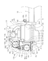
- FIG. 3 is a left side view showing the internal configuration of the engine compartment.
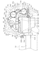
- FIG. 4 is a right side view showing the internal configuration of the engine compartment.
- FIG. 5 is a front view showing the internal configuration of the engine compartment.
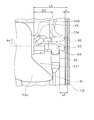
- FIG. 6 is an enlarged view of the vicinity of the injector viewed from the front of the vehicle.
- FIG. 7 is a front view showing the internal configuration of the engine room of the bulldozer according to a modification of the embodiment of the present invention.
- FIG. 6 is an enlarged view of the vicinity of the injector viewed from the front of the vehicle according to a modification of the embodiment of the invention.
- FIG. 2 is a plan view showing a part of a bulldozer according to an embodiment of the present invention.
- FIG. 2 shows the engine chamber 8 in a state where an engine cover 13 described later is removed.
- the front-rear direction means the front-rear direction of the bulldozer 1.
- the front-rear direction means the front-rear direction viewed from an operator seated in the cab (cab) 12.
- the left-right direction means a left-right direction viewed from an operator seated in the cab (operator's cab) 12.
- the side means the vehicle width direction of the bulldozer 1, that is, the left direction or the right direction described above.
- the bulldozer 1 includes a traveling device 2, a vehicle main body 3, and a work implement 4.
- the traveling device 2 is a device for traveling the vehicle and has a crawler belt 11. The bulldozer 1 travels when the crawler belt 11 is driven.
- the vehicle body 3 includes a body frame 10 (see FIG. 2), a cab 12, an engine cover 13, and a cooling device 14 (see FIG. 1).
- the engine cover 13 is disposed in front of the cab 12.
- An engine chamber 8 (see FIG. 2) in which the engine 5 is housed is located in the engine cover 13.
- the upper surface 13a of the engine cover 13 is inclined rearward toward the upper side.
- the cooling device 14 is disposed behind the cab 12. Generally, in a bulldozer, the cooling device is disposed in front of the engine in the engine cover in front of the cab.
- the cooling device 14 includes, for example, a radiator that cools the coolant of the engine 5 and an oil cooler that cools hydraulic oil.
- the work machine 4 is provided in front of the engine cover 13.
- the work machine 4 includes a blade 15 and a hydraulic cylinder 16.
- the blade 15 is provided so as to be swingable in the vertical direction.
- the hydraulic cylinder 16 includes a first cylinder 16a, a second cylinder 16b, a third cylinder 16c, and a fourth cylinder 16d.
- the first cylinder 16 a and the third cylinder 16 c are disposed on the left side of the engine cover 13.
- the second cylinder 16b and the fourth cylinder 16d are disposed on the right side of the engine cover 13.
- the first cylinder 16a and the second cylinder 16b move the blade 15 up and down.
- the third cylinder 16c and the fourth cylinder 16d change the posture of the blade 15. That is, the first cylinder 16a to the fourth cylinder 16d control the position or posture of the blade 15.
- FIG. 3 is a left side view showing the internal configuration of the engine compartment 8 in the engine cover 13.
- FIG. 4 is a right side view showing the internal configuration of the engine compartment 8 in the engine cover 13. The right side in FIG. 4 shows the front side of the vehicle.
- FIG. 5 is a front view showing the internal configuration of the engine compartment 8 in the engine cover 13.
- the vehicle body frame 10 and the engine cover 13 are shown by two-dot chain lines in FIGS. 3 and 4.
- the vehicle body frame 10 is omitted, and the engine cover 13 is illustrated by a two-dot chain line. 2 to 5, a part of the configuration inside the engine chamber 8 is omitted as appropriate.
- the vehicle body 3 includes an engine 5, a flywheel housing 6, and a hydraulic pump 7.
- the engine 5 is disposed in the engine cover 13.
- the engine 5 is a diesel engine, and the output of the engine 5 is controlled by adjusting the fuel injection amount from a fuel injection pump (not shown).
- the engine 5 includes a crankcase 22, an oil pan 23, a cylinder body 24, a cylinder head 25, and a cylinder head cover 26.
- Engine 5 includes a crankshaft (not shown).
- the crankshaft extends in the vehicle front-rear direction.
- the engine 5 is a so-called vertical engine, and a long side is arranged in the vehicle front-rear direction and a short side is arranged in the vehicle width direction. With this arrangement, the width of the vehicle can be reduced, and thus visibility to the left and right lower ends of the blade 15 required for the bulldozer can be obtained.
- Ax4 indicates the center axis of the crankshaft.
- the crankcase 22 houses a crankshaft.
- a cam pulley (not shown) is disposed in front of the crankcase 22.
- the crankshaft is connected to the cam pulley.
- a belt 27 is wound around the cam pulley.
- the oil pan 23 is disposed below the crankcase 22.
- the cylinder body 24 is disposed on the upper side of the crankcase 22.
- the cylinder head 25 is disposed on the upper side of the cylinder body 24.
- the cylinder head cover 26 is disposed on the upper side of the cylinder head 25.
- the engine 5 includes a supercharger 28.
- the supercharger 28 is connected to the cylinder head 25 via an exhaust pipe 29 (see FIG. 4) of the engine 5.
- the supercharger 28 is disposed on the side of the cylinder head 25 in the vehicle plan view. In the vehicle side view, at least a part of the supercharger 28 is located above the upper surface of the engine 5, that is, the upper surface of the cylinder head cover 26.
- the flywheel housing 6 is disposed behind the engine 5.
- the hydraulic pump 7 is disposed behind the flywheel housing 6 and is attached to the flywheel housing 6.
- the hydraulic pump 7 is connected to the output shaft of the engine 5 via a flywheel.
- the hydraulic pump 7 discharges hydraulic oil by being driven by a driving force from the engine 5.
- the vehicle body 3 includes an air cleaner 33 and a duct 34.
- the air cleaner 33 and the duct 34 are disposed below the upper surface 13 a of the engine cover 13.
- the air cleaner 33 is disposed above the engine 5.
- the air cleaner 33 is fixed to the engine cover 13.
- the air cleaner 33 has a cylindrical shape.
- a central axis Ax5 of the air cleaner 33 shown in FIG. 2 is arranged substantially horizontally along the vehicle width direction.
- the air cleaner 33 includes an intake port (not shown) and an exhaust port 331 (see FIGS. 2 and 4).
- the intake port is connected to the head portion 35 (see FIG. 1) via a pipe member (not shown).
- the head portion 35 protrudes upward from the upper surface of the engine cover 13.
- the exhaust port 331 is provided on the side surface of the air cleaner 33.
- the exhaust port 331 is located above the supercharger 28 described above.
- the duct 34 connects the air cleaner 33 and the engine 5.
- the duct 34 extends downward from the exhaust port 331 of the air cleaner 33 and has a shape bent toward the supercharger 28.
- the duct 34 includes a first connection portion 36, a second connection portion 37, and a vibration absorbing portion 38.
- the first connection portion 36 is connected to the engine 5.
- the first connection portion 36 is connected to the supercharger 28.
- the second connection part 37 is connected to the air cleaner 33.
- the second connection portion 37 is connected to the exhaust port 331 of the air cleaner 33.
- the vibration absorbing portion 38 is located between the first connection portion 36 and the second connection portion 37 in the duct 34.
- the vibration absorber 38 has a bellows shape.
- the vehicle body 3 includes a first exhaust treatment device 41, a second exhaust treatment device 42, a relay connection pipe 43, a first connection pipe 45, and a second connection pipe 46.
- the first connection pipe 45 connects the engine 5 and the first exhaust treatment device 41. More specifically, the first connection pipe 45 connects the supercharger 28 and the first exhaust treatment device 41 described above.
- the second connection pipe 46 is connected to the second exhaust treatment device 42 and discharges the exhaust from the engine 5 processed by the second exhaust treatment device 42.
- the second connection pipe 46 is connected to the exhaust pipe 47 shown in FIG.
- the exhaust pipe 47 is disposed so as to protrude upward from the engine cover 13.
- the first exhaust treatment device 41 is, for example, a diesel particulate filter device, and processes exhaust from the engine 5 sent through the first connection pipe 45.
- the first exhaust treatment device 41 collects particulate matter contained in the exhaust with a filter.
- the first exhaust treatment device 41 incinerates the collected particulate matter with a heater attached to the filter.
- the first exhaust treatment device 41 is disposed at the foremost position in the engine cover 13 in front of the engine 5. Such an arrangement is made possible by the cooling device 14 being arranged not behind the engine cover 13 but behind the cab 12. Further, the first exhaust treatment device 41 is disposed below the upper surface of the engine 5. Specifically, the first exhaust treatment device 41 is disposed below the upper surface of the cylinder head cover 26. The first exhaust treatment device 41 is disposed above the bottom surface of the oil pan 23.
- the first exhaust treatment device 41 has a substantially cylindrical outer shape.
- the vehicle width direction dimension of the first exhaust treatment device 41 is larger than the vehicle width direction dimension of the engine 5.
- the first exhaust treatment device 41 is arranged such that its central axis Ax1 is along the vehicle width direction. That is, the longitudinal direction of the first exhaust treatment device 41 is along the vehicle width direction.
- the first exhaust treatment device 41 has a first connection port 41a and a second connection port 41b.
- the 1st connection pipe 45 is connected to the 1st connection port 41a.
- the relay connection pipe 43 is connected to the second connection port 41b.
- the first connection port 41a protrudes obliquely upward. Specifically, the first connection port 41a protrudes obliquely upward and toward the engine 5 side.
- the first connection pipe 45 extends obliquely downward from the connection position with the engine 5 toward the first exhaust treatment device 41. Accordingly, the first exhaust treatment device 41 is disposed at a position that does not overlap the engine 5 in plan view. That is, at least one of the first exhaust treatment device 41 and the second exhaust treatment device 42 is disposed at a position that does not overlap the engine 5 in plan view.
- the second connection port 41b is inclined slightly forward from the vertical direction. Therefore, as shown in FIG. 2, the central axis Ax3 of the straight portion 43b (details will be described later) of the relay connecting pipe 43 is located slightly ahead of the central axis Ax1 in plan view.
- the relay connection pipe 43 connects the first exhaust treatment device 41 and the second exhaust treatment device 42. As shown in FIGS. 3 and 5, the outer diameter of the relay connection pipe 43 is smaller than the outer diameter of the first exhaust treatment device 41 and the outer diameter of the second exhaust treatment device 42. One end of the relay connection pipe 43 is connected to the second connection port 41 b of the first exhaust treatment device 41. The other end of the relay connection pipe 43 is connected to the third connection port 42 a of the second exhaust treatment device 42.
- the relay connection pipe 43 is disposed in front of the engine 5 and above the first exhaust treatment device 41. Furthermore, as shown in FIG. 5, the relay connection pipe 43 overlaps with a part of the first connection pipe 45 in the vehicle front view. As shown in FIG. 4, the relay connection pipe 43 passes through a position close to the first connection pipe 45.
- the relay connection pipe 43 has a first bent portion 43a, a straight portion 43b, and a second bent portion 43c.
- the straight portion 43 b is located above the first exhaust treatment device 41.
- the linear part 43b is arrange
- the longitudinal direction of the relay connection pipe 43 is along the vehicle width direction.
- the first bent portion 43a connects the straight portion 43b and the second connection port 41b.
- the second bent portion 43 c connects the straight portion 43 b and the third connection port 42 a of the second exhaust treatment device 42.
- An injector 44 is attached to the first bent portion 43a.
- the injector 44 injects a reducing agent into the relay connection pipe 43.
- the reducing agent is, for example, urea water. Details of the shape of the injector 44 and the first bent portion 43a will be described later.
- the second exhaust treatment device 42 is, for example, a selective reduction catalyst device.
- the second exhaust processing device 42 processes the exhaust from the engine 5 processed by the first exhaust processing device 41.
- the second exhaust treatment device 42 selectively reduces nitrogen oxides NOx.
- the second exhaust treatment device 42 has a substantially cylindrical outer shape. As shown in FIG. 5, the second exhaust treatment device 42 is arranged such that the central axis Ax2 is along the vehicle width direction. Further, the second exhaust treatment device 42 is arranged such that the central axis Ax2 thereof is parallel to the central axis Ax1 of the first exhaust treatment device 41. That is, the longitudinal direction of the second exhaust treatment device 42 is along the vehicle width direction.
- the second exhaust treatment device 42 is arranged in front of the engine 5. More specifically, the second exhaust treatment device 42 is arranged such that the central axis Ax2 of the second exhaust treatment device 42 is in front of the front end of the engine 5. The second exhaust treatment device 42 is arranged such that the central axis Ax2 of the second exhaust treatment device 42 is above the upper end of the relay connection pipe 43. That is, the second exhaust treatment device 42 is disposed above the first exhaust treatment device 41 and the relay connection pipe 43. Since the relay connection pipe 43 is disposed above the first exhaust treatment apparatus 41 and below the second exhaust treatment apparatus 42, the first exhaust treatment apparatus 41, the relay connection pipe 43, and the second exhaust treatment apparatus 42 are disposed. Are arranged side by side in the vertical direction. Further, the second exhaust treatment device 42 is disposed above the first connection pipe 45.
- the second exhaust treatment device 42 is disposed so as to overlap a part of the first exhaust treatment device 41 in a plan view. Further, the second exhaust treatment device 42 is disposed so as to overlap a part of the engine 5 in a plan view. That is, the second exhaust treatment device 42 has a portion that overlaps with the engine 5 in a plan view of the vehicle. More specifically, as shown in FIGS. 3 and 4, the second exhaust treatment device 42 is disposed so as to overlap the belt 27 of the engine 5 in plan view.
- the center Az1 in the vehicle longitudinal direction of the first exhaust treatment device 41 and the center Az2 in the vehicle longitudinal direction of the second exhaust treatment device 42 are considered.
- Az1 is a plane passing through the central axis Ax1 and extending along the vertical direction.
- Az2 is a plane passing through the central axis Ax1 and extending along the vertical direction.
- Az1 and Az2 are represented by straight lines.
- the side surfaces of the first exhaust treatment device 41 the first surface in front of the center Az1 in the vehicle front-rear direction and in the side surfaces of the second exhaust treatment device 42, the first surface in front of the center Az2 in the vehicle front-rear direction.
- the tangent line L is inclined rearward toward the upper side.
- the front end of the first exhaust treatment device 41 is located in front of the front end of the second exhaust treatment device 42.
- the front end of the relay connection pipe 43 is located in front of the vehicle with respect to the tangent line L.
- the rear end of the relay connection pipe 43 is located behind the tangent L in the vehicle side view.
- the second exhaust treatment device 42 has a third connection port 42a and a fourth connection port 42b.
- a relay connection pipe 43 is connected to the third connection port 42a.
- a second connection pipe 46 is connected to the fourth connection port 42b. That is, the second connection pipe 46 is connected to the second exhaust treatment device 42.
- the third connection port 42a is inclined slightly downward from the horizontal direction toward the front.
- the fourth connection port 42b protrudes obliquely upward.
- the fourth connection port 42b protrudes obliquely upward and toward the engine 5 side.
- the second connection pipe 46 projects obliquely upward above the engine 5.
- the engine cover 13 can be lowered as compared with the case where the fourth connection port 42b is arranged directly above.
- the upper part of the second connection pipe 46 protrudes upward from the engine cover 13.
- the engine 5, the first connection pipe 45, the first exhaust treatment device 41, the relay connection pipe 43, the second exhaust treatment device 42, the second connection pipe 46, and the exhaust pipe 47 are connected in series in order. Has been. Therefore, the exhaust from the engine 5 passes through the first connection pipe 45 and is sent to the first exhaust treatment device 41. In the first exhaust treatment device 41, the particulate matter is mainly reduced from the exhaust. Next, the exhaust passes through the relay connection pipe 43 and is sent to the second exhaust treatment device 42. In the second exhaust treatment device 42, NOx is mainly reduced. Thereafter, the cleaned exhaust gas is discharged to the outside through the second connection pipe 46 and the exhaust pipe 47.
- the first exhaust treatment device 41, the relay connection pipe 43, the second exhaust treatment device 42, and the air cleaner 33 are arranged so as to surround the front and upper sides of the engine 5. Accordingly, the first exhaust treatment device 41, the relay connection pipe 43, the second exhaust treatment device 42, and the air cleaner 33 can be closely and closely arranged.
- the engine cover 13 covers the engine 5, the air cleaner 33, the first exhaust treatment device 41, the second exhaust treatment device 42, the relay connection pipe 43, and the injector 44.
- the upper surface 13 a of the engine cover 13 extends along the second exhaust treatment device 42 and the air cleaner 33.
- the front surface 13 b of the engine cover 13 extends along the first exhaust treatment device 41 and the relay connection pipe 43.
- the engine cover 13 further includes a curved surface 13c that smoothly connects the upper surface 13a and the front surface 13b. By providing the curved surface 13c, a region above the blade 15 that can be visually recognized by the operator is widened.
- FIG. 1 shows this content.
- FIG. 1 shows an upper region of the blade 15 viewed from the viewpoint 100 of an operator sitting on the cab 12 as a region between the straight lines 110 and 120.
- the viewpoint 100 corresponds to a light source position (filament position-centre-point: FPCP) defined in ISO 5006.
- the viewpoint 100 is a point that is raised by 680 mm in the vertical direction from the seat reference point (seat index point: SIP) defined in ISO 5006.
- a straight line 110 is a straight line connecting the viewpoint 100 and the upper end of the blade 15.
- a straight line 120 is a straight line passing through the viewpoint 100 and in contact with the engine cover 13.
- the straight line 120 is in contact with the curved surface 13c, and by providing the curved surface 13c, the region above the blade 15 that can be visually recognized by the operator is expanded.
- the straight line connecting the viewpoint 100 and the upper end of the blade 15 is located above the engine cover 13 in the vehicle side view.
- the vehicle main body 3 includes a mount bracket 50, a first support bracket 70, a second support bracket 80, a rear mount bracket 90, and dampers 31L, 31R, 32L, and 32R.
- the mount bracket 50 is disposed in the engine cover 13.
- the mount bracket 50 and the rear mount bracket 90 support the engine 5 on the vehicle body frame 10 via dampers 31L, 31R, 32L, and 32R.
- the damper 31L is supported by the mount bracket support portion 10a of the vehicle body frame 10.
- the damper 31 ⁇ / b> R is supported by the mount bracket support portion 10 b of the vehicle body frame 10. That is, the mount bracket 50 is attached to the vehicle body frame 10 via the dampers 31L and 31R.
- the dampers 31L and 31R include elastic bodies such as rubber inside. Therefore, the mount bracket 50 is elastically supported by the mount bracket support portions 10a and 10b of the vehicle body frame 10 via the damper 31L and the damper 31R.
- the mount bracket 50 is attached to the engine 5 at the first connection portion 52, the second connection portion 61, and the third connection portion 64. Therefore, the engine 5 is elastically supported by the vehicle body frame via the mount bracket 50 and the dampers 31L and 31R.
- the mount bracket 50 supports the first support bracket 70 and the second support bracket 80.
- the first support bracket 70 is attached to the mount bracket 50 and directly supports the first exhaust treatment device 41.
- the first exhaust treatment device 41 is fixed to the first support bracket 70 by wire-like fixing members 78 and 79. Therefore, the first exhaust treatment device 41 is elastically supported by the vehicle body frame 10 via the first support bracket 70 and the mount bracket 50.
- the second support bracket 80 is attached to the mount bracket 50 and directly supports the second exhaust treatment device 42. As shown in FIG. 5, the second exhaust treatment device 42 is fixed to the second support bracket 80 by wire-like fixing members 88 and 89. Accordingly, the second exhaust treatment device 42 is elastically supported by the vehicle body frame 10 via the second support bracket 80 and the mount bracket 50.
- the damper 32L is supported by the mount bracket support portion 10c of the vehicle body frame 10.
- the damper 32 ⁇ / b> R is supported by the mount bracket support portion 10 d of the vehicle body frame 10. That is, the rear mount bracket 90 is attached to the vehicle body frame 10 via the dampers 32L and 32R.
- the dampers 32L and 32R include elastic bodies such as rubber inside. Therefore, the rear mount bracket 90 is elastically supported by the mount bracket support portions 10c and 10d of the vehicle body frame 10 via the damper 32L and the damper 32R.
- the rear mount bracket 90 is attached to the rear surface of the flywheel housing 6.
- the engine 5 is connected to the rear mount bracket 90 via the flywheel housing 6. Therefore, the engine 5 is elastically supported by the vehicle frame 10 via the rear mount bracket 90 and the dampers 32L and 32R.
- FIG. 6 is an enlarged view of the vicinity of the injector 44 as viewed from the front of the vehicle.
- the injector 44 is attached to the attachment surface 432 in the offset part 431 of the first bent part 43a.
- the outer shape of the relay connection pipe 43 without the offset portion 431 (hereinafter referred to as a first outer shape) is illustrated by a dotted line.
- side surfaces 13 d, heat insulating material 13 f, and overhang portion 13 e described below are shown in cross-sectional shapes, and a part of the configuration inside and outside the engine compartment 8 is appropriately omitted.
- the attachment surface 432 is provided in an offset portion 431 that is offset from the first outer shape toward the central axis Az3 of the second connection port 41b.
- the size D1 of the offset portion 431 in the longitudinal direction Ax3 of the relay connection pipe 43 is longer than the length D2 of the injector 44 in the longitudinal direction Ax3 of the relay connection pipe 43.
- the side surface of the engine cover 13 closest to the injector 44 is defined as 13d.
- the distance between the side surface 13d in the longitudinal direction Ax3 of the relay connection pipe 43 and the first exhaust treatment device 41 is L1
- the distance between the side surface 13d in the longitudinal direction Ax3 of the relay connection pipe 43 and the mounting surface 432 When the distance is L2, L1 ⁇ L2.
- the distance (L2-D2) between the side surface 13d and the injector 44 in the longitudinal direction Ax3 of the relay connection pipe 43 is longer than the distance L1.
- the injector 44 cools the water heated by the pipe 91 for sending the reducing agent from the reducing agent tank (not shown) to the injector 44, the pipe 92 for sending the cooling water from the cooling device 14 to the injector 44, and the relay connection pipe 43.
- a tube 93 for returning to the device 14 is connected.
- the pipe 92 may be a pipe for returning the water heated by the relay connection pipe 43 to the cooling device 14, and the pipe 93 may be a pipe for sending the cooling water from the cooling device 14 to the injector 44.
- An L-shaped plug 94 for connecting to the injector 44 may be provided at the end of the tube 92.
- the one in which the pipes 91, 92, 93 are connected to the injector 44 is referred to as an injector assembly 95.
- the relay connection pipe 43 and the second exhaust treatment device 42 generate heat because a chemical reaction occurs. Therefore, it is desirable to provide the heat insulating material 13f inside the engine cover 13.
- 5 and 6 show an example in which a heat insulating material 13f having a thickness d is arranged inside the side surface 13d.
- the region indicated by the dot pattern corresponds to the heat insulating material 13 f.
- at least a part of the pipes 91, 92, 93 and the plug 94 is located outside the heat insulating material 13f. Therefore, in the present embodiment, as shown in FIGS. 1 to 3, 5, and 6, the overhanging portion 13 e is provided in a portion of the side surface 13 d corresponding to the injector 44. That is, the side surface 13d includes an overhang portion 13e.
- the overhang portion 13e is preferably formed by a cover separate from the engine cover 13. In this case, as shown in FIG. 6, the overhang portion 13e is fixed to the side surface 13d by bolts 131a, 131b and the like. In FIG. 3, the overhanging portion 13e is illustrated by a two-dot chain line. As shown in FIG. 3, the overhanging portion 13 e covers most of the region corresponding to the injector 44 in the vehicle side view. Accordingly, in the region corresponding to the injector 44, a gap is provided in the longitudinal direction Ax3 of the relay connection pipe 43 by a distance L3 (L3> L2) between the protruding portion 13e and the mounting surface 432.
- the distance L3 between the overhanging portion 13e and the mounting surface 432 is longer than the length D2 of the injector 44 in the longitudinal direction Ax3 of the relay connecting pipe 43.
- the distance between the injector assembly 95 and the overhanging portion 13e is L5.
- the distance L5 corresponds to the distance between the rigid portion that is connected to the injector 44 of the pipes 91, 92, and 93 and the protruding portion 13e. That is, the distance L5 is the distance between the plug 94 and the inner wall of the overhang portion 13e.
- the distance L5 is substantially equal to the distance L1 between the side surface 13d and the first exhaust treatment device 41. That is, the absolute value of the difference between the distance L1 and the distance L5 is smaller than 5% of the width W2 (see FIG. 2) of the engine cover 13 in the vehicle width direction.
- the absolute value of the difference between the distance L1 and the distance L5 is smaller than 2% of the width W2 (see FIG. 2) of the engine cover 13 in the vehicle width direction.
- the difference between the distance L1 and the distance L5 is less than 50 mm. More preferably, the difference between the distance L1 and the distance L5 is less than 20 mm.
- the distance W1 between the first cylinder 16a and the second cylinder 16b is the length of the relay connection pipe 43 at the position of the injector 44. It is longer than the width W2 of the engine cover 13 in the direction Ax3. That is, the distance W1 between the first cylinder 16a and the second cylinder 16b is longer than the width W2 of the engine cover 13 in the vehicle width direction at the position of the injector 44.
- the distance W1 between the first cylinder 16a and the second cylinder 16b is the distance between the portion of the first cylinder 16a closest to the second cylinder 16b and the portion of the second cylinder 16b closest to the first cylinder 16a. Is the distance between.
- FIG. 1 shows a straight line that represents the upper end of the first cylinder 16a when the first cylinder 16a is located highest in the movable range of the first cylinder 16a by a one-dot chain line UL.
- the movable range of the 1st cylinder 16a does not overlap with the overhang
- the bulldozer 1 has the following features.
- the first exhaust treatment device 41, the second exhaust treatment device 42, and the relay connection pipe 43 are arranged in front of the engine 5. Thereby, even if the first exhaust treatment device 41, the second exhaust treatment device 42, and the relay connection pipe 43 are housed in the engine chamber 8, it is possible to suppress the rise of the upper surface of the engine cover 13. Therefore, the area
- first exhaust treatment device 41, the relay connection pipe 43, and the second exhaust treatment device 42 are arranged side by side so that their longitudinal directions are along the vehicle width direction. Further, the attachment surface of the injector 44 in the relay connection pipe 43 is provided in the offset portion of the relay connection pipe 43 at the connection portion between the first exhaust treatment device 41 and the relay connection pipe 43. Further, the distance L5 between the side surface 13d of the engine cover 13 closest to the injector assembly 95 and the injector assembly 95 and the distance L1 between the side surface 13d and the first exhaust treatment device 41 are substantially equal.
- the distance L5 between the side surface 13d of the engine cover 13 and the injector assembly 95 is made equal to the distance L1 between the side surface 13d and the first exhaust treatment device 41, so that there is no need for interference due to vibration generated when the bulldozer 1 moves. Set to the minimum clearance. Thereby, an increase in the vertical width and the horizontal width of the engine chamber 8 can be suppressed.
- the distance L3 between the protruding portion 13e and the mounting surface 432 in the longitudinal direction of the relay connection pipe 43 is longer than the length D2 of the injector 44 in the longitudinal direction of the relay connection pipe 43.
- the distance between the first cylinder 16a and the second cylinder 16b is longer than the width of the engine cover 13 in the longitudinal direction of the relay connection pipe 43 at the position of the injector 44. As a result, the cylinder that drives the blade 15 does not interfere with the engine cover 13.
- the side surface 13 d of the engine cover 13 closest to the injector 44 has a protruding portion 13 e corresponding to the position of the injector 44.
- the overhang portion 13e is formed by a cover separate from the engine cover 13.
- the cover corresponding to the overhanging portion 13 e can be removed, and the tubes 91, 92, 93 and the plug 94 attached to the injector 44 can be removed. Therefore, it is possible to prevent the engine cover 13 from becoming difficult to remove due to the pipes 91, 92, 93, the plug 94, and the like attached to the injector 44 coming into contact with the engine cover 13 when the engine cover 13 is removed.
- the movable range of the cylinder closest to the overhanging portion 13e does not overlap with the overhanging portion 13e in a side view of the vehicle.
- the cylinder that drives the blade 15 does not interfere with the overhanging portion 13e.
- the relay connection pipe 43 is located above the first exhaust treatment apparatus 41, and the second exhaust treatment apparatus 42 is located above the relay connection pipe 43. Accordingly, the position of the overhanging portion 13e can be increased to a position where the movable range of the cylinder 16a closest to the overhanging portion 13e does not overlap with the overhanging portion 13e in a vehicle side view.
- the protruding portion 13e is provided on the side surface 13d of the engine cover 13 closest to the injector 44.
- the protruding portion may not be provided on the side surface 13d, and the side surface 13d may be flat.
- FIG. 7 is a front view showing the internal configuration of the engine room 8 of the bulldozer according to this modification.
- FIG. 8 is an enlarged view of the vicinity of the injector 44 as viewed from the front of the vehicle according to this modification.
- the first bent portion 43a without the offset portion 431 is illustrated by a dotted line.
- those cross-sectional shapes are displayed.
- the distance between the side surface 13d and the attachment surface 432 in the longitudinal direction Ax3 of the relay connection pipe 43 is changed from L2 to L4.
- the size of the offset portion 431 in the longitudinal direction Ax3 of the relay connection pipe 43 may be changed from D1 to D3.
- a heat insulating material 13f is also provided in a portion corresponding to the injector 44 in the side surface 13d. Therefore, the distance (L4-d) between the attachment surface 432 and the heat insulating material 13f in the longitudinal direction Ax3 of the relay connection pipe 43 is longer than L2 described above.
- the distance (L4-d) is preferably not less than L3. Also in this case, as in the above embodiment, the distance L5 between the injector assembly 95 and the overhanging portion 13e is substantially equal to the distance L1 between the side surface 13d and the first exhaust treatment device 41.
- the distance between the crawler belts 11 and the distance between the first cylinder 16a and the second cylinder 16b are widened, and the width of the engine cover 13 is widened without changing the size D1 of the offset portion 431. It is possible to increase the distance between the mounting surface 432 and the heat insulating material 13f.
- the distance between the mounting surface 432 and the heat insulating material 13f can be increased by increasing the size of the offset portion 431 in the longitudinal direction Ax3 of the relay connection pipe 43 from D1 to D3.
- the interval between the crawler belts 11 and the interval between the first cylinder 16a and the second cylinder 16b may be increased, and the lateral width of the engine cover 13 may not be increased. Even in such a case, the cylinder that drives the blade 15 does not interfere with the engine cover 13.
- the shape of the engine cover 13, in particular, the overhang portion 13e is not limited to the above shape, and may be changed as appropriate.
- the shapes of the injector 44, the pipes 91, 92, 93, and the plug 94 are not limited to the above shapes, and may be changed as appropriate.
- the shapes of the mount bracket 50 and the rear mount bracket 90 are not limited to the above shapes, and may be changed as appropriate.
- the shape of the 1st support bracket 70 and the 2nd support bracket 80 is not restricted to said shape, You may change suitably. Further, the mount bracket 50, the first support bracket 70, and the second support bracket 80 may be integrally formed.
- the above embodiment shows a case where the distance L5 is equal to the distance L1.
- the distance L5 may be equal to the distance between the second exhaust treatment device 42 and the side surface 13d.
- the first exhaust treatment device 41 is described as a diesel particulate collection filter device, and the second exhaust treatment device 42 is described as a selective reduction catalyst device.
- the first exhaust treatment device 41 may be a selective reduction catalyst device
- the second exhaust treatment device 42 may be a diesel particulate filter device.
- the exhaust from the engine is preferably sent first to the diesel particulate filter device, in this case, the order and direction of the pipes connected to the first exhaust treatment device 41 and the second exhaust treatment device 42 are the same. The reverse is true.
- the first exhaust treatment device 41 may not be a diesel particulate filter device, but may be a diesel oxidation catalyst (Diesel Oxidation Catalyst: DOC).
- DOC Diesel Oxidation Catalyst
- the number of dampers 31L, 31R, 32L, 32R is arbitrary. However, it is desirable that the same number of dampers be provided in the left-right direction.
Landscapes
- Engineering & Computer Science (AREA)
- General Engineering & Computer Science (AREA)
- Chemical & Material Sciences (AREA)
- Mechanical Engineering (AREA)
- Combustion & Propulsion (AREA)
- Civil Engineering (AREA)
- Structural Engineering (AREA)
- Mining & Mineral Resources (AREA)
- Chemical Kinetics & Catalysis (AREA)
- Health & Medical Sciences (AREA)
- Toxicology (AREA)
- Transportation (AREA)
- Exhaust Gas After Treatment (AREA)
- Cooling, Air Intake And Gas Exhaust, And Fuel Tank Arrangements In Propulsion Units (AREA)
- Component Parts Of Construction Machinery (AREA)
Abstract
Description
作業性が向上されている。
本発明の一実施形態に係るブルドーザ1の左側面図を図1に示す。本発明の一実施形態に係るブルドーザの一部を示す平面図を図2に示す。図2では、後述するエンジンカバー13が取り外された状態のエンジン室8を示している。なお、以下の説明において、前後方向とは、ブルドーザ1の前後方向を意味する。言い換えれば、前後方向とは、キャブ(運転室)12に着座したオペレータから見た前後方向を意味する。また、左右方向とは、キャブ(運転室)12に着座したオペレータから見た左右方向を意味する。側方とは、ブルドーザ1の車幅方向、すなわち、前述の左方向もしくは右方向のいずれかを意味する。
図3は、エンジンカバー13内のエンジン室8の内部構成を示す左側面図である。図4は、エンジンカバー13内のエンジン室8の内部構成を示す右側面図である。図4での右側が、車両の前側を示す。図5は、エンジンカバー13内のエンジン室8の内部構成を示す正面図である。なお、理解の容易のため、図3及び図4では、車体フレーム10及びエンジンカバー13が二点鎖線で図示されている。図5では、車体フレーム10が省略され、エンジンカバー13が二点鎖線で図示されている。また、図2~図5において、エンジン室8内の構成の一部を適宜省略している。図2~図4に示すように、車両本体3は、エンジン5と、フライホイールハウジング6と、油圧ポンプ7とを含む。エンジン5は、エンジンカバー13内に配置されている。
車両本体3は、第1排気処理装置41、第2排気処理装置42、中継接続管43、第1接続管45、及び、第2接続管46を含む。第1接続管45は、エンジン5と第1排気処理装置41とを接続する。より詳細には、第1接続管45は、前述した過給器28と第1排気処理装置41とを接続する。第2接続管46は、第2排気処理装置42に接続し、第2排気処理装置42に処理されたエンジン5からの排気を排出する。第2接続管46は、図1に示される排気管47に接続されている。排気管47は、エンジンカバー13から上方に突出するように配置されている。
図2~図4に示すように、第1排気処理装置41、中継接続管43、第2排気処理装置42、及び、エアークリーナ33は、エンジン5の前方及び上方を取り囲むように配置される。これによって、第1排気処理装置41、中継接続管43、第2排気処理装置42、及び、エアークリーナ33を、近づけて密に配置することができる。
図3及び図4に示すように、車両本体3は、マウントブラケット50、第1支持ブラケット70、第2支持ブラケット80、後マウントブラケット90、及びダンパー31L,31R,32L,32Rを含む。マウントブラケット50は、エンジンカバー13内に配置されている。マウントブラケット50と後マウントブラケット90とは、ダンパー31L,31R,32L,32Rを介して、エンジン5を車体フレーム10上で支持している。
図6は、車両前方から見たインジェクタ44付近の拡大図である。図6に示すように、インジェクタ44は、第1屈曲部43aのオフセット部431にある取付面432に取り付けされている。図6では、オフセット部431がない中継接続管43の外形(以下、第1外形と呼ぶ)を点線で図示している。また、図6において、後述する側面13d、断熱材13f及び張出部13eについては、それらの断面形状が表示されており、エンジン室8内外の構成の一部が適宜省略されている。取付面432は、第1外形から第2接続口41bの中心軸線Az3に向かってオフセットしたオフセット部431に設けられている。中継接続管43の長手方向Ax3におけるオフセット部431の大きさD1は、中継接続管43の長手方向Ax3におけるインジェクタ44の長さD2より長い。
本実施形態に係るブルドーザ1は、以下の特徴を有する。
以上、本発明の一実施形態について説明したが、本発明は上記実施形態に限定されるものではなく、発明の要旨を逸脱しない範囲で種々の変更が可能である。
Claims (8)
- ブレードと、
エンジンと、
前記エンジンの前方に配置され、前記エンジンからの排気を処理する第1排気処理装置と、
前記エンジンの前方に配置され、前記エンジンからの排気を処理する第2排気処理装置と、
前記エンジンの前方に配置され、前記第1排気処理装置と前記第2排気処理装置とを接続する中継接続管と、
前記中継接続管に取り付けられ、前記中継接続管の内部に還元剤を噴射するインジェクタを含むインジェクタアセンブリと、
前方且つ下方に向かって傾斜する上面を有し、前記エンジン、前記第1排気処理装置、前記第2排気処理装置、前記中継接続管、及び前記インジェクタを覆うエンジンカバーと、
を備え、
前記第1排気処理装置、前記中継接続管、及び前記第2排気処理装置は、それらの長手方向が車幅方向に沿うように並んで配置され、
前記中継接続管における前記インジェクタの取付面は、前記第1排気処理装置と前記中継接続管との接続部において、前記中継接続管のオフセット部に設けられ、
前記インジェクタアセンブリに最も近い前記エンジンカバーの第1側面と前記インジェクタアセンブリとの間の距離と、前記第1側面と前記第1排気処理装置との間の距離とが実質的に等しい、ブルドーザ。 - 前記中継接続管の長手方向における前記取付面と前記第1側面との間の距離は、前記中継接続管の長手方向における前記インジェクタの長さよりも長い、請求項1に記載のブルドーザ。
- 前記エンジンカバーの左側方に配置され、前記ブレードの位置または姿勢を制御する第1シリンダと、
前記エンジンカバーの右側方に配置され、前記ブレードの位置または姿勢を制御する第2シリンダと、
をさらに備え、
前記第1シリンダと前記第2シリンダとの間の距離は、前記インジェクタの位置における、前記中継接続管の長手方向の前記エンジンカバーの幅よりも長い、請求項1又は2に記載のブルドーザ。 - 前記インジェクタに最も近い前記エンジンカバーの側面は、前記インジェクタの位置に対応する張出部を有する、請求項1から3のいずれかに記載のブルドーザ。
- 前記張出部は、前記エンジンカバーとは別体のカバーにより形成される、請求項4に記載のブルドーザ。
- 前記第1シリンダ及び前記第2シリンダのうち、前記張出部に最も近いシリンダの可動範囲は、車両側面視において前記張出部と重畳しない、請求項4または5に記載のブルドーザ。
- 前記中継接続管は、前記第1排気処理装置の上方に位置し、前記第2排気処理装置は、前記中継接続管の上方に位置する、請求項6に記載のブルドーザ。
- 前記インジェクタに最も近い前記エンジンカバーの側面は、平坦である、請求項3に記載のブルドーザ。
Priority Applications (4)
| Application Number | Priority Date | Filing Date | Title |
|---|---|---|---|
| JP2014517919A JP5576583B1 (ja) | 2013-04-26 | 2013-04-26 | ブルドーザ |
| PCT/JP2013/062476 WO2014174683A1 (ja) | 2013-04-26 | 2013-04-26 | ブルドーザ |
| CN201380004510.XA CN104136690B (zh) | 2013-04-26 | 2013-04-26 | 推土机 |
| US14/372,160 US9394668B2 (en) | 2013-04-26 | 2013-04-26 | Bulldozer |
Applications Claiming Priority (1)
| Application Number | Priority Date | Filing Date | Title |
|---|---|---|---|
| PCT/JP2013/062476 WO2014174683A1 (ja) | 2013-04-26 | 2013-04-26 | ブルドーザ |
Publications (1)
| Publication Number | Publication Date |
|---|---|
| WO2014174683A1 true WO2014174683A1 (ja) | 2014-10-30 |
Family
ID=51579051
Family Applications (1)
| Application Number | Title | Priority Date | Filing Date |
|---|---|---|---|
| PCT/JP2013/062476 Ceased WO2014174683A1 (ja) | 2013-04-26 | 2013-04-26 | ブルドーザ |
Country Status (4)
| Country | Link |
|---|---|
| US (1) | US9394668B2 (ja) |
| JP (1) | JP5576583B1 (ja) |
| CN (1) | CN104136690B (ja) |
| WO (1) | WO2014174683A1 (ja) |
Cited By (3)
| Publication number | Priority date | Publication date | Assignee | Title |
|---|---|---|---|---|
| JP2017112991A (ja) * | 2015-12-22 | 2017-06-29 | 株式会社クボタ | 収穫機 |
| WO2017110530A1 (ja) * | 2015-12-22 | 2017-06-29 | 株式会社クボタ | 収穫機 |
| JP2019100024A (ja) * | 2017-11-29 | 2019-06-24 | 株式会社Kcm | 作業車両 |
Families Citing this family (11)
| Publication number | Priority date | Publication date | Assignee | Title |
|---|---|---|---|---|
| US9487079B2 (en) * | 2014-08-11 | 2016-11-08 | Deere & Company | Air inlet and cleaner arrangement for work vehicle |
| EP2985166B1 (en) * | 2014-08-14 | 2017-08-02 | CNH Industrial Italia S.p.A. | Exhaust system for an off-road vehicle |
| JP5719092B1 (ja) * | 2014-08-25 | 2015-05-13 | 株式会社小松製作所 | ブルドーザ |
| LT3178998T (lt) * | 2014-09-03 | 2019-05-27 | Shantui Construction Machinery Co., Ltd. | Buldozeris |
| JP6449021B2 (ja) * | 2015-01-05 | 2019-01-09 | 株式会社クボタ | 作業車 |
| CN105899738B (zh) * | 2015-08-21 | 2019-07-09 | 株式会社小松制作所 | 液压挖掘机 |
| CN109072753B (zh) | 2016-02-19 | 2021-01-29 | 洋马动力科技有限公司 | 发动机装置 |
| CA2958965C (en) * | 2016-08-03 | 2019-01-08 | Komatsu Ltd. | Working vehicle |
| US12077938B2 (en) * | 2021-10-12 | 2024-09-03 | Caterpillar Inc. | Secondary control system and method for mounting with service orientation |
| KR20240035041A (ko) | 2022-09-08 | 2024-03-15 | 에이치디현대인프라코어 주식회사 | 도저 |
| KR20240035045A (ko) * | 2022-09-08 | 2024-03-15 | 에이치디현대인프라코어 주식회사 | 도저 |
Citations (4)
| Publication number | Priority date | Publication date | Assignee | Title |
|---|---|---|---|---|
| JP2008240695A (ja) * | 2007-03-28 | 2008-10-09 | Komatsu Ltd | 建設車両 |
| JP2012154031A (ja) * | 2011-01-21 | 2012-08-16 | Komatsu Ltd | 作業車両 |
| JP2012215022A (ja) * | 2011-03-31 | 2012-11-08 | Komatsu Ltd | エンジンユニット |
| JP2012240518A (ja) * | 2011-05-18 | 2012-12-10 | Hitachi Constr Mach Co Ltd | 建設機械 |
Family Cites Families (17)
| Publication number | Priority date | Publication date | Assignee | Title |
|---|---|---|---|---|
| US8695722B2 (en) | 2003-10-09 | 2014-04-15 | Komatsu Ltd. | Bulldozer with improved visibility |
| CN201314058Y (zh) * | 2008-12-05 | 2009-09-23 | 山推工程机械股份有限公司 | 推土机工作控制装置 |
| GB2466277A (en) * | 2008-12-19 | 2010-06-23 | Agco Gmbh | Exhaust systems for vehicles |
| US20110079003A1 (en) | 2009-10-05 | 2011-04-07 | Caterpillar Inc. | Reductant nozzle indentation mount |
| US9180774B2 (en) * | 2010-05-31 | 2015-11-10 | Komatsu Ltd. | Work vehicle |
| JP5325316B1 (ja) * | 2012-04-24 | 2013-10-23 | 株式会社小松製作所 | ブルドーザ |
| JP5261589B1 (ja) * | 2012-04-24 | 2013-08-14 | 株式会社小松製作所 | ブルドーザ |
| US9476337B2 (en) * | 2012-07-05 | 2016-10-25 | Komatsu Ltd. | Engine unit and work vehicle |
| DE112013000161C5 (de) * | 2013-03-15 | 2023-03-16 | Komatsu Ltd. | Abgasnachbehandlungseinheit und ein diese enthaltendes Baufahrzeug |
| WO2014155507A1 (ja) * | 2013-03-26 | 2014-10-02 | 株式会社小松製作所 | 作業車両、及びホイールローダ |
| WO2014155510A1 (ja) * | 2013-03-26 | 2014-10-02 | 株式会社小松製作所 | ホイールローダ |
| JP5635694B1 (ja) * | 2013-03-26 | 2014-12-03 | 株式会社小松製作所 | 作業車両、及びホイールローダ |
| JP5624692B1 (ja) * | 2013-04-26 | 2014-11-12 | 株式会社小松製作所 | ブルドーザ |
| KR101630253B1 (ko) * | 2013-09-25 | 2016-06-14 | 가부시키가이샤 고마쓰 세이사쿠쇼 | 작업 차량 |
| WO2015045106A1 (ja) * | 2013-09-27 | 2015-04-02 | 株式会社小松製作所 | 作業車両 |
| DE112013000191B4 (de) * | 2013-09-27 | 2017-08-24 | Komatsu Ltd. | Reduktionsmittelbehälter und Arbeitsfahrzeug |
| CN103874598B (zh) * | 2013-09-30 | 2016-08-31 | 株式会社小松制作所 | 推土机 |
-
2013
- 2013-04-26 JP JP2014517919A patent/JP5576583B1/ja active Active
- 2013-04-26 WO PCT/JP2013/062476 patent/WO2014174683A1/ja not_active Ceased
- 2013-04-26 CN CN201380004510.XA patent/CN104136690B/zh active Active
- 2013-04-26 US US14/372,160 patent/US9394668B2/en active Active
Patent Citations (4)
| Publication number | Priority date | Publication date | Assignee | Title |
|---|---|---|---|---|
| JP2008240695A (ja) * | 2007-03-28 | 2008-10-09 | Komatsu Ltd | 建設車両 |
| JP2012154031A (ja) * | 2011-01-21 | 2012-08-16 | Komatsu Ltd | 作業車両 |
| JP2012215022A (ja) * | 2011-03-31 | 2012-11-08 | Komatsu Ltd | エンジンユニット |
| JP2012240518A (ja) * | 2011-05-18 | 2012-12-10 | Hitachi Constr Mach Co Ltd | 建設機械 |
Cited By (3)
| Publication number | Priority date | Publication date | Assignee | Title |
|---|---|---|---|---|
| JP2017112991A (ja) * | 2015-12-22 | 2017-06-29 | 株式会社クボタ | 収穫機 |
| WO2017110530A1 (ja) * | 2015-12-22 | 2017-06-29 | 株式会社クボタ | 収穫機 |
| JP2019100024A (ja) * | 2017-11-29 | 2019-06-24 | 株式会社Kcm | 作業車両 |
Also Published As
| Publication number | Publication date |
|---|---|
| JP5576583B1 (ja) | 2014-08-20 |
| JPWO2014174683A1 (ja) | 2017-02-23 |
| US9394668B2 (en) | 2016-07-19 |
| US20160115671A1 (en) | 2016-04-28 |
| CN104136690B (zh) | 2016-01-20 |
| CN104136690A (zh) | 2014-11-05 |
Similar Documents
| Publication | Publication Date | Title |
|---|---|---|
| JP5576583B1 (ja) | ブルドーザ | |
| JP5624692B1 (ja) | ブルドーザ | |
| JP5261589B1 (ja) | ブルドーザ | |
| CN103797195B (zh) | 作业车辆 | |
| CN103890276B (zh) | 液压挖掘机 | |
| US9010480B2 (en) | Bulldozer | |
| CN104302884B (zh) | 排气处理单元 | |
| CN104185708B (zh) | 推土机 | |
| WO2014141513A1 (ja) | 排気処理ユニット及び排気処理ユニットを搭載する作業車両 | |
| CN104254676B (zh) | 发动机单元 | |
| US20140237994A1 (en) | Exhaust apparatus for four wheeled utility vehicle | |
| KR101801511B1 (ko) | 작업 차량 | |
| JP5698420B1 (ja) | ブルドーザ | |
| CN101469624B (zh) | 排气系统与跨乘式车辆 | |
| JP2012127330A (ja) | 車両用エンジンの吸気装置 | |
| JP5481604B1 (ja) | 排気処理ユニット及び排気処理ユニットを搭載する作業車両 | |
| JP2019100024A (ja) | 作業車両 | |
| JP2018100610A (ja) | 車体構造 |
Legal Events
| Date | Code | Title | Description |
|---|---|---|---|
| ENP | Entry into the national phase |
Ref document number: 2014517919 Country of ref document: JP Kind code of ref document: A |
|
| WWE | Wipo information: entry into national phase |
Ref document number: 14372160 Country of ref document: US |
|
| 121 | Ep: the epo has been informed by wipo that ep was designated in this application |
Ref document number: 13883095 Country of ref document: EP Kind code of ref document: A1 |
|
| NENP | Non-entry into the national phase |
Ref country code: DE |
|
| 122 | Ep: pct application non-entry in european phase |
Ref document number: 13883095 Country of ref document: EP Kind code of ref document: A1 |