WO2014171024A1 - 掘削バケット及び作業車両 - Google Patents
掘削バケット及び作業車両 Download PDFInfo
- Publication number
- WO2014171024A1 WO2014171024A1 PCT/JP2013/076117 JP2013076117W WO2014171024A1 WO 2014171024 A1 WO2014171024 A1 WO 2014171024A1 JP 2013076117 W JP2013076117 W JP 2013076117W WO 2014171024 A1 WO2014171024 A1 WO 2014171024A1
- Authority
- WO
- WIPO (PCT)
- Prior art keywords
- bucket
- surface portion
- excavation
- lip
- excavation bucket
- Prior art date
- Legal status (The legal status is an assumption and is not a legal conclusion. Google has not performed a legal analysis and makes no representation as to the accuracy of the status listed.)
- Ceased
Links
Images




Classifications
-
- E—FIXED CONSTRUCTIONS
- E02—HYDRAULIC ENGINEERING; FOUNDATIONS; SOIL SHIFTING
- E02F—DREDGING; SOIL-SHIFTING
- E02F3/00—Dredgers; Soil-shifting machines
- E02F3/04—Dredgers; Soil-shifting machines mechanically-driven
- E02F3/28—Dredgers; Soil-shifting machines mechanically-driven with digging tools mounted on a dipper- or bucket-arm, i.e. there is either one arm or a pair of arms, e.g. dippers, buckets
- E02F3/36—Component parts
- E02F3/40—Dippers; Buckets ; Grab devices, e.g. manufacturing processes for buckets, form, geometry or material of buckets
-
- E—FIXED CONSTRUCTIONS
- E02—HYDRAULIC ENGINEERING; FOUNDATIONS; SOIL SHIFTING
- E02F—DREDGING; SOIL-SHIFTING
- E02F3/00—Dredgers; Soil-shifting machines
- E02F3/04—Dredgers; Soil-shifting machines mechanically-driven
- E02F3/28—Dredgers; Soil-shifting machines mechanically-driven with digging tools mounted on a dipper- or bucket-arm, i.e. there is either one arm or a pair of arms, e.g. dippers, buckets
- E02F3/30—Dredgers; Soil-shifting machines mechanically-driven with digging tools mounted on a dipper- or bucket-arm, i.e. there is either one arm or a pair of arms, e.g. dippers, buckets with a dipper-arm pivoted on a cantilever beam, i.e. boom
- E02F3/32—Dredgers; Soil-shifting machines mechanically-driven with digging tools mounted on a dipper- or bucket-arm, i.e. there is either one arm or a pair of arms, e.g. dippers, buckets with a dipper-arm pivoted on a cantilever beam, i.e. boom working downwardly and towards the machine, e.g. with backhoes
-
- E—FIXED CONSTRUCTIONS
- E02—HYDRAULIC ENGINEERING; FOUNDATIONS; SOIL SHIFTING
- E02F—DREDGING; SOIL-SHIFTING
- E02F9/00—Component parts of dredgers or soil-shifting machines, not restricted to one of the kinds covered by groups E02F3/00 - E02F7/00
- E02F9/28—Small metalwork for digging elements, e.g. teeth scraper bits
- E02F9/2808—Teeth
Definitions
- the present invention relates to an excavation bucket and a work vehicle.
- the excavation bucket equipped in the work vehicle includes a plurality of teeth, a bracket, and a bucket body.
- the tooth is provided on the upper front side of the bucket body.
- the bracket is provided on the back surface of the bucket body.
- the bracket is provided with a hole, and the excavation bucket is attached to the arm by passing the attachment pin through the hole. Accordingly, the excavation bucket is attached to the arm so as to be rotatable around the attachment pin.
- the conventional excavation bucket has the following problems. That is, when it is desired to increase the capacity of the excavation bucket, if the capacity of the excavation bucket is increased by increasing the width of the excavation bucket, twisting or the like is likely to occur during operation, and the burden on the arm increases.
- An object of the present invention is to provide a drilling bucket and a work vehicle capable of increasing the capacity while suppressing the burden on the arm in consideration of the problem of the conventional drilling bucket.
- the excavation bucket according to the first invention is an excavation bucket that is attached to an arm of a work vehicle, and includes a bucket body, a lip portion, a bracket, and a cutting blade portion.
- the bucket body is a pair of side surfaces covering the side of a space surrounded by a bottom surface portion having two curved portions having different curvature radii in a side view, a back surface portion connected to the bottom surface portion, and the bottom surface portion and the back surface portion.
- the lip portion is fixed to an edge portion located on the opposite side of the back surface portion in the bucket body.
- the bracket has a hole through which an attachment pin for attachment to the arm is passed, and is fixed to the back surface portion.
- the cutting blade portion is fixed to the lip portion.
- the length of the imaginary line connecting the center of the hole of the bracket and the tip of the lip is defined as the wrist radius.
- the longest line segment from the virtual line perpendicular to the virtual line to the bottom surface is defined as the second virtual line, and the length is defined as the bucket depth.
- the size of the angle formed by the lip portion and the virtual line is defined as the lip angle.
- the curvature of the bottom surface can be increased and the bucket depth can be increased, so that the capacity (bucket capacity) is increased even with the same width as the conventional excavation bucket. Can be planned.
- the capacity can be increased without changing the width of the excavation bucket, it is possible to increase the capacity while suppressing the burden on the arm.
- the excavation bucket rotates around the hole of the bracket, but by making the lip angle ⁇ 72 ° or less, the bottom surface portion does not protrude below the locus of the tip of the cutting edge. I can do it. Therefore, excavation resistance can be reduced.
- the lip angle ⁇ is larger than 72 °, the curvature of the bottom surface portion becomes large, and it may be difficult to ensure the soil removal performance of the excavated soil. For this reason, the soil removal property can be ensured by setting the lip angle ⁇ to 72 ° or less.
- the excavation bucket of the first invention can set the wrist radius to the same length as the conventional excavation bucket. . Since the control value on the main body side of the hydraulic excavator is set by the wrist radius, the excavation bucket according to the first invention can be easily replaced without changing the control value. Furthermore, by setting the bucket depth / list radius to 0.7 or more, the bucket depth becomes deeper, and the capacity can be increased as compared with the conventional case. Further, when the bucket depth / list radius is greater than 0.8, the bucket depth may be too deep with respect to the wrist radius, and it may be difficult to ensure soil removal performance, or the excavation resistance may increase. For this reason, by setting the bucket depth / list radius to 0.8 or less, it is possible to ensure the soil removal performance while reducing the excavation resistance.
- the excavation bucket according to the second invention is the excavation bucket according to the first invention, and when the width of the excavation bucket (bucket width) is Z, 0.73 ⁇ D / Z ⁇ 0.83 is satisfied. .
- the bucket capacity relative to the bucket width can be increased. That is, by setting the bucket depth / bucket width value to 0.73 or more, the bucket capacity can be made larger than that of the conventional one even if the width is the same as that of the conventional excavation bucket.
- the bucket depth / bucket width value is larger than 0.83, the bucket depth with respect to the bucket width becomes too deep, and it may be difficult to ensure the soil removal performance, or the excavation resistance may increase. Therefore, by setting the value of the bucket depth / bucket width to 0.83 or less, it is possible to ensure the soil removal performance while reducing the excavation resistance.
- a work vehicle includes a vehicle main body, a boom attached to the vehicle main body, an arm attached to the boom, and the excavation bucket of the first invention or the second invention attached to the arm.
- the excavation bucket and work vehicle which can aim at the increase in a capacity
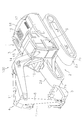
- FIG. 1 is an external perspective view of a hydraulic excavator according to an embodiment of the present invention.
- the perspective view of the excavation bucket of FIG. The side view in the horizontal state of the excavation bucket of FIG.
- FIG. 3 is a rear view of the excavation bucket of FIG. 2.
- trajectory of the excavation bucket of FIG. The side view which shows the excavation bucket of the comparative example 1.
- FIG. The figure which shows the locus
- the side view of the excavation bucket of this Embodiment arrange
- the side view of the excavation bucket of the comparative example 2 arrange
- the side view of the excavation bucket of the comparative example 3 arrange
- FIG. The figure which shows the graph of the pushing force index
- FIG. The side view which shows the excavation bucket of this Embodiment and the excavation bucket of the comparative example 2.
- FIG. The figure which shows the graph of the change of excavation resistance index when changing a lip angle.
- FIG. 1 is a diagram showing a hydraulic excavator 100 according to an embodiment of the present invention.
- the excavator 100 includes a vehicle main body 1 and a work machine 4.
- the vehicle body 1 has a traveling body 2 and a revolving body 3.
- the traveling body 2 includes a pair of traveling devices 2a and 2b.
- Each traveling device 2a, 2b has crawler belts 2d, 2e, and the crawler belts 2d, 2e are driven by the driving force from the engine to cause the excavator 100 to travel.
- the turning body 3 is placed on the traveling body 2.
- the swivel body 3 is provided so as to be turnable with respect to the traveling body 2.
- a cab 5 is provided at the front left side position of the revolving structure 3.
- the front-rear direction means the front-rear direction of the cab 5.
- the front-rear direction of the vehicle body 1 is assumed to coincide with the front-rear direction of the cab 5, that is, the revolving structure 3.
- the left-right direction or the side means the vehicle width direction of the vehicle main body 1.
- the revolving unit 3 includes a fuel tank 14, a hydraulic oil tank 15, an engine chamber 16, and a storage chamber 17.
- the fuel tank 14 stores fuel for driving an engine described later.
- the fuel tank 14 is disposed in front of the hydraulic oil tank 15.
- the hydraulic oil tank 15 stores hydraulic oil discharged from a hydraulic pump (not shown) and supplied to the hydraulic cylinders 10 to 12.
- the engine chamber 16 houses the engine therein.
- the storage compartment 17 is arranged behind the cab 5 and is arranged side by side with the engine compartment 16 in the vehicle width direction. Inside the storage chamber 17, a storage space for storing a radiator and a radiator fan (not shown) for cooling the engine is provided inside the storage chamber 17, a storage space for storing a radiator and a radiator fan (not shown) for cooling the engine is provided.
- a counterweight 18 is provided behind the engine chamber 16 and the storage chamber 17.
- the work machine 4 is attached to the center position of the front part of the revolving structure 3 and has a boom 7, an arm 8, and an excavation bucket 9.
- a base end portion of the boom 7 is rotatably connected to the swing body 3.
- the distal end portion of the boom 7 is rotatably connected to the proximal end portion of the arm 8.
- the tip of the arm 8 is rotatably connected to the excavation bucket 9.
- hydraulic cylinders 10 to 12 (boom cylinder 10, arm cylinder 11 and bucket cylinder 12) are arranged so as to correspond to boom 7, arm 8 and excavation bucket 9, respectively.
- the working machine 4 is driven by driving these hydraulic cylinders 10 to 12. Thereby, operations such as excavation are performed.
- FIG. 2 is a perspective view of the excavation bucket 9 according to the embodiment of the present invention.
- FIG. 3 is a side view of the excavation bucket 9 of FIG. 4 is a side view of the excavation bucket 9 of FIG. 2, and is a view in which the inclination of the excavation bucket 9 is different from that of FIG.
- FIG. 5 is a rear view of the excavation bucket 9 of FIG.
- the excavation bucket 9 includes a bucket body 21, a lip portion 35, a tooth adapter 24, a bracket 22, and a plurality of teeth 23.
- the bucket body 21 has a front surface portion 31, a bottom surface portion 32, a back surface portion 33, and a pair of side surface portions 34.
- the front part 31 is a flat plate-like member, and has a linear shape in a side view.
- the bottom surface portion 32 is a curved plate-like member, and has a shape curved convexly toward the outside of the bucket body 21 in a side view.
- the bottom surface portion 32 is connected to the front surface portion 31.
- the back surface portion 33 has a shape in which a plate-like member is bent.
- the back surface portion 33 is connected to the bottom surface portion 32.
- the pair of side surface portions 34 are arranged at a distance from each other, and cover the side of the space surrounded by the front surface portion 31, the bottom surface portion 32, and the back surface portion 33.
- the lip portion 35 is a flat plate-like member and has a linear shape in a side view.
- the lip portion 35 is a portion to which the tooth adapter 24 is attached and the tooth 23 is fixed.
- the lip portion 35 is fixed to an edge portion located on the opposite side of the back surface portion 33 in the bucket body 21. Specifically, the lip portion 35 is fixed to the edge portion of the front surface portion 31.
- the thickness of the lip portion 35 is larger than the thickness of the front surface portion 31.
- the bracket 22 is a member for attaching the excavation bucket 9 to the arm.
- the bracket 22 is fixed to the back surface portion 33.
- the bracket 22 has two attachment portions 22 a that are erected outward from the back surface portion 33.
- Each attachment portion 22 a is a plate-like member, and is arranged in a direction perpendicular to the width direction of the excavation bucket 9. Further, the two attachment portions 22a are provided to face each other with a gap W as shown in FIG. This interval is defined as a bracket width W.
- a first hole 38 and a second hole 39 are formed in each attachment portion 22a.
- An attachment pin (not shown) for attaching the bracket 22 to the arm is passed through the first hole 38.
- the 2nd hole 39 is formed in the bottom face part 32 side of the 1st hole 38, and the attachment pin (not shown) for attaching bracket 22 to bucket cylinder 12 (refer to Drawing 1) is passed.
- the plurality of teeth 23 are fixed to the lip portion 35 via the tooth adapter 24.
- the teeth 23 are disposed along the end portion of the lip portion 35 so as to be spaced apart from each other.
- Each tooth 23 has a tapered shape in a side view.
- the bottom surface portion 32 described above has a first curved surface portion 41 and a second curved surface portion 42.
- the first curved surface portion 41 is connected to the front surface portion 31. Therefore, the front surface portion 31 is located between the first curved surface portion 41 and the lip portion 35.
- the first curved surface portion 41 has a shape curved with a predetermined first curvature radius R1 in a side view.
- the center O1 of the radius of curvature of the first curved surface portion 41 is located outside the bucket body 21. Further, in the side view, the center O1 is located above and behind the center of the first hole 38 in the state shown in FIG.
- the second curved surface portion 42 is located on the back surface portion 33 side, that is, the rear side of the first curved surface portion 41 and is connected to the first curved surface portion 41.
- the second curved surface portion 42 has a shape curved with a predetermined second radius of curvature R2 in a side view.
- the second curvature radius R2 is smaller than the first curvature radius R1.
- the center O2 of the radius of curvature of the second curved surface portion 42 is located inside the bucket body 21.
- the length of a virtual line S1 (an example of a virtual line) connecting the center Q1 of the first hole 38 of the bracket 22 and the tip Q2 of the lip portion 35 in a side view is defined as a wrist radius V.
- the tip Q2 is the tip of the inner flat surface 35a of the lip portion 35.
- a virtual plane including the inner plane 35a of the lip portion 35 is set as a reference plane S3.
- an angle formed by the reference plane S3 and the wrist radius V is defined as a lip angle ⁇ .
- the end of the first curved surface portion 41 located on the lip portion 35 side that is, the connection portion P1 between the front surface portion 31 and the first curved surface portion 41 is in contact with the first curved surface portion 41, and the hole A virtual curved surface having a curved shape with a radius of curvature of the excavation diameter S5 (see FIG. 3) from the center of 38 to the tip of the tooth 23 is defined as a reference curved surface S2.
- a state where the virtual line S1 is horizontally disposed and the bottom surface portion 32 is positioned below the virtual line S1 is referred to as a “horizontal state”.
- the first curved surface portion 41 is disposed along the reference curved surface S2 in a side view.
- the connecting portion P2 between the first curved surface portion 41 and the second curved surface portion 42 is in front of the portion P3 located on the lowermost side of the bottom surface portion 32 in the horizontal state, that is, the front surface portion.
- the lowermost portion P ⁇ b> 3 of the bottom surface portion 32 in the horizontal state is included in the second curved surface portion 42. That is, the excavation bucket 9 according to the present embodiment has the first curved surface portion 41 larger than the excavation bucket 109 according to Comparative Example 1 described later in FIG. 7, but the second curved surface portion 42 is excessively reduced. It is secured largely without. For this reason, earth and sand easily flows into the bucket body 21.
- the length of the virtual line S4 (an example of the second virtual line) lowered vertically from the virtual line S1 toward the portion P3 is defined as a bucket depth D.
- the virtual line S4 can be said to be the longest line segment among the line segments from the virtual line S1 perpendicular to the virtual line S1 to the bottom surface portion 32 in a side view.
- the length of the front surface portion 31 is smaller than the length of the first curved surface portion 41 in the direction along the lip portion 35 in the side view.
- the length L 1 of the front surface portion 31 in the direction along the lip portion 35 is smaller than the length L 2 of the first curved surface portion 41 in the direction along the lip portion 35. For this reason, the lip part 35 can be shortened.
- the lip portion 35 is formed thicker than the front surface portion 31 in order to increase the strength, the longer the lip portion 35, the higher the manufacturing cost. Therefore, the manufacturing cost can be reduced by shortening the lip portion 35. Moreover, when forming the bottom face part 32 by roll-processing a board
- the length L1 of the front surface portion 31 in the direction along the lip portion 35 is smaller than the length L3 between the lip portion 35 and the tooth 23 in the direction along the lip portion 35.
- the length of the front surface portion 31 in the direction along the lip portion 35 is smaller than the second curvature radius R2.
- the connection portion P ⁇ b> 1 between the front surface portion 31 and the first curved surface portion 41 is located at a position higher than the center O ⁇ b> 2 of the curvature radius of the second curved surface portion 42.
- the angle ⁇ formed by the imaginary line S ⁇ b> 1 and the back surface portion 33 is an obtuse angle in a side view.
- the back surface portion 33 In the horizontal state, the back surface portion 33 is inclined so as to be located rearward as the lower side. The upper portion of the back surface portion 33 is located in front of the first hole 38, and the lower portion of the back surface portion 33 is located below the first hole 38.
- the space inside the bucket body 21 has a shape that expands toward the rear side as it goes down. For this reason, a wide rear space is secured in the bucket body 21. For this reason, the capacity
- the width of the upper end of the excavation bucket 9 is defined as a bucket width Z
- the width of the bottom portion of the excavation bucket 9 is defined as a bucket bottom width Y.
- the ratio (hereinafter referred to as “list radius ratio”) R1 / V between the list radius V and the first curvature radius R1 satisfies the following (Equation 5).
- Equation 5 0.65 ⁇ R1 / V ⁇ 1.2
- R1 / V 1.12.
- the first curved surface portion 41 is disposed along the reference curved surface S2.
- the reference curved surface S2 is a curved surface that approximates the locus of the tip of the tooth 23 during excavation. For this reason, the first curved surface portion 41 is arranged along the reference curved surface S2, whereby the contact pressure between the bottom surface portion 32 and the ground can be reduced.
- FIG. 6 shows the trajectory of the excavation bucket 9 when excavation is performed by moving the excavation bucket 9 according to the present embodiment while moving the arm 8 (see FIG. 1).
- the arrows in the figure indicate the traveling direction of the excavation bucket 9.
- a broken line G1 indicates the ground.
- a two-dot chain line T1 indicates a locus T1 of the tip of the tooth 23.
- the excavation bucket 9 does not enter the ground, and the tooth 23 enters the ground (the state (A) in FIG. 6) from the state where the tip of the tooth 23 is in contact with the ground (the state (A) in FIG. 6).
- the state of B)) and the operation of the excavation bucket 9 until the tooth 23 is in a horizontal posture in the ground the state of (C) in FIG.
- the excursion width of the arm 8 during excavation is such that the position of the first hole 38 after movement does not exceed the position of the tip of the tooth 23 before movement.
- the bottom surface portion 32 is along the trajectory T ⁇ b> 1 of the tip of the tooth 23 in the state (D). For this reason, in the excavation bucket 9 according to the present embodiment, during excavation, the contact pressure between the bottom surface portion 32 of the excavation bucket 9 and the ground can be reduced, and the excavation resistance can be reduced.
- FIG. 7 is a side view of the excavation bucket 109 according to the first comparative example.
- the excavation bucket 109 according to the comparative example has a wrist radius V (the length of the first imaginary line S101) having the same length as the excavation bucket 9 according to the present embodiment.
- the curvature radius R101 of the first curved surface portion 141 is smaller than the wrist radius V, and the center O101 of the curvature radius R101 of the first curved surface portion 141 is located inside the excavation bucket 109 in the side view, and is described above. Does not satisfy the formula (Equation 5).
- the length L101 of the front part 131 of the excavation bucket 109 which concerns on a comparative example is longer than the length L1 of the front part 31 of the excavation bucket 9 which concerns on this Embodiment.
- the length L101 of the front surface portion 131 is longer than the length L102 of the first curved surface portion 141 in the direction along the lip portion 135.
- the front surface part 131 and the 1st curved surface part 141 are connected by the connection part P10.
- the first curved surface portion 141 and the second curved surface portion 142 are connected at the connection portion P20.
- the lowermost portion P ⁇ b> 30 of the bottom surface portion 132 in the horizontal state is included in the second curved surface portion 142.
- FIG. 8 the locus of the excavation bucket 109 when the excavation bucket 109 is moved while moving the arm 8 is shown in FIG.
- the swinging width of the arm 8 during excavation is the same as that in FIG.
- a two-dot chain line T ⁇ b> 101 indicates a locus T ⁇ b> 101 at the tip of the tooth 23.
- a part of the bottom surface portion 132 protrudes below the locus T101 at the tip of the tooth 123. Therefore, in the excavation bucket 109 according to the comparative example 1, during excavation, the contact pressure between the bottom surface portion 132 of the excavation bucket 109 and the ground increases, and the excavation resistance increases.
- the protruding portion is indicated by M.
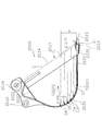
- FIG. 9 is a side view of the excavation bucket 9 according to the present embodiment arranged so that the lip portion 35 is in a horizontal state.
- the lip angle ⁇ in the excavation bucket 9 shown in FIG. 9 is 64 °
- the wrist radius V is 1771 mm
- the bucket depth D is 1234 mm
- the first curvature radius R1 is 1800 mm
- the second radius of curvature R2 is set to 650 mm
- the bucket capacity V is 3.6 m 3 .
- F be the portion along the virtual line S1 from the tip of the lip portion 35 by a length (ie, 0.27 V) 0.27 times the length of the virtual line S1 (list radius V).
- a point where the horizontal line passing through F and the bottom surface part 32 intersect is defined as G6.
- the tip end portion of the lip portion 35 is denoted by G1.
- This G1 is the same position as Q2, and is the tip of the flat portion inside the lip portion 35.
- the width H of the horizontal line passing through G1 and the horizontal line passing through G6 is divided into five equal parts, and the points at which the respective horizontal lines divided into five and the bottom surface part 32 intersect are designated as G2, G3, G4, and G5 in order from the G1 side.
- the area from G1 to G6 is defined as an excavation area.
- the vertical component of the reaction force generated on the wall surface when a force is applied to each of the points G1 to G6 in the direction of the arrow J The force k1 was used, and the horizontal component k2 was used as the pushing force.
- FIG. 10 is a side view of the excavation bucket 1009 according to the second comparative example.
- the excavation bucket 1009 according to Comparative Example 2 satisfies the above (Equation 5) but has a lip angle ⁇ smaller than 62 ° and does not satisfy the above (Equation 1).
- the excavation bucket 1009 shown in FIG. 10 includes a bucket body 1021, a lip portion 1035, a tooth adapter 1024, a bracket 1022, and a plurality of teeth 1023.
- the bucket body 1021 includes a front surface portion 1031, a bottom surface portion 1032, a back surface portion 1033, and a pair of side surface portions 1034.
- the bottom surface portion 1032 includes a first curved surface portion 1041 and a second curved surface portion 1042.
- the first curved surface portion 1041 is connected to the front surface portion 1031.
- the bracket 1022 is provided with holes 1038 and 1039 for attaching the arm. Further, FIG.
- the excavation bucket 1009 of this comparative example 2 has a bucket capacity of 2.1 m 3 and a bucket depth of 1021 mm.
- the lip angle ⁇ of Comparative Example 2 is formed at 52 °.
- FIG. 11 is a side view in which the excavation bucket 1009 of Comparative Example 2 is arranged so that the lip portion 1035 is horizontal.
- the excavation area was set for the excavation bucket 1009 of Comparative Example 2 as in FIG. 9, and points G1 to G6 were determined. Further, the same investigation was performed on the excavation bucket of Comparative Example 3 shown in FIG.
- Excavation bucket 2009 shown in Comparative Example 3 shown in FIG. 12 is different from excavation bucket 9 of the embodiment, and bottom surface portion 2032 is configured by one curved surface portion having a predetermined radius of curvature R6 in a side view.
- the excavation bucket 2009 includes a bucket body 2021, a lip portion 2035, a tooth adapter 2024, a bracket 2022, and a plurality of teeth 2023.
- the bucket body 2021 includes a front surface portion 2031, a bottom surface portion 2032, a back surface portion 2033, and a pair of side surface portions 2034.
- the bottom surface portion 2032 is configured by a curved surface portion having a curvature radius R6 with O2002 as the center.
- the bracket 2022 is provided with holes 2038 and 2039 for attaching the arm.
- FIG. 12 shows a connection portion P2001 between the front surface portion 2031 and the bottom surface portion 2032.
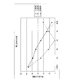
- FIG. 13 is a graph showing wall resistance indices at points G1 to G6 in Example 1, Comparative Example 2, and Comparative Example 3.
- the solid line indicates Example 1
- the dotted line indicates Comparative Example 2
- the alternate long and short dash line indicates data of Comparative Example 3.
- the wall resistance index shown in FIG. 13 indicates the degree of change when the force applied in the arrow J direction is 100.
- FIG. 14 is a diagram showing a graph of the pushing force index at points G1 to G6 in Example 1, Comparative Example 2, and Comparative Example 3.
- the solid line indicates Example 1
- the dotted line indicates Comparative Example 2
- the alternate long and short dash line indicates data of Comparative Example 3.
- the pushing force index shown in FIG. 14 indicates the degree of change when the force applied in the arrow J direction is 100.
- the wall surface resistance force suddenly increases in G2, and the pushing force becomes zero in G4. Therefore, in G5 and G6, the pushing force is reversed and becomes resistance.
- Example 1 and Comparative Example 2 that satisfy (Equation 5), both the wall resistance force and the pushing force change smoothly, which is preferable.
- the bottom surface portion 32 includes the first curved surface portion 41 and the second curved surface 42, so that the bottom surface portion is composed of one curved surface portion as compared with Comparative Example 7. Both the wall resistance force and the pushing force change smoothly, which is preferable. That is, the excavation bucket 9 of this embodiment can obtain suitable wall resistance and pushing force by satisfying (Equation 5).
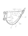
- FIG. 15 is a diagram illustrating an excavation bucket having a lip angle of 62 degrees or more and an excavation bucket of Comparative Example 2 as an example of the present embodiment.
- the excavation bucket 9 of an example of this embodiment is shown by a solid line
- the excavation bucket 1009 of the comparative example 2 is shown by a two-dot chain line.
- a reference plane in the excavation bucket 1009 of Comparative Example 2 is indicated as S1003, and an imaginary line indicating the list radius is indicated as S1001.
- an imaginary line indicating the bucket depth of the comparative example is indicated by S1004.
- the lip angle ⁇ 1 of the digging bucket 9 of the example of the present embodiment is formed larger than the lip angle ⁇ 1001 of the digging bucket 1009 of the comparative example 2.
- the excavation bucket 9 as an example of the present embodiment has a larger curvature of the bottom surface portion 32 than the excavation bucket 1009 of the comparative example 2, and increases the bucket depth D as indicated by virtual lines S4 and S1004. I can do it. Therefore, in the excavation bucket 9 as an example of the present embodiment, even if the excavation bucket 1009 of the comparative example 2 has the same bucket width Z and bucket bottom width Y, the bucket capacity V can be increased.
- the bucket capacity can be 2.3 m 3 .
- the packet capacity V is 2.1 m 3.
- the bucket capacity can be increased as compared with the conventional excavation bucket.
- the excavation buckets of Examples 3, 4 and 5 have lip angles ⁇ of 68 °, 70 ° and 72 °, and the excavation buckets of Comparative Examples 5, 6 and 7 have lip angles ⁇ of 64 °, 76 ° and 78 °. What was set to ° was used.
- the protruding amount and excavation resistance index when the excavation bucket is moved while moving the arm 8 (see FIG. 1) as shown in FIGS. 6 and 8 are as follows (Table 2). Show.
- the following excavation groove depth is a depth from the ground surface to the deepest position when excavating the ground.
- the protruding amount is an amount protruding from the locus T101 as indicated by M in FIG.
- the results of Table 2 are shown in a graph in FIG.
- the excavation resistance index indicates the degree of change in excavation resistance when the excavation resistance when there is no protrusion is 100.
- FIG. 16 when the lip angle ⁇ is larger than 72 °, it can be seen that a ledge appears and the excavation resistance index increases. From this, it can be seen that the excavation resistance can be prevented from increasing by setting the lip angle ⁇ to 72 ° or less as in the excavation bucket 9 of the present embodiment.
- satisfying (Equation 5), and further satisfying (Equation 1) has good wall resistance and pushing force, does not cause a protrusion, and increases excavation resistance. It does not occur and the bucket capacity can be increased.
- Example 7 The lip angle ⁇ is set to 70.7 °, the wrist radius V is set to 2157 mm, the bucket depth D is set to 1424 mm, the bracket width W is set to 371 mm (0.371 m), the bucket width Z is set to 1715 mm, and the first curvature radius R1 is set to 1700 mm.
- the bucket capacity V can be set to 3.9 m 3 .
- the second curvature radius R2 can be set to 500 mm, and the bucket bottom width Y can be set to 1373 mm.
- the excavation bucket 9 of the above embodiment is an excavation bucket 9 attached to the arm 8 of the excavator 100, and includes a bucket body 21, a lip portion 35, a bracket, and a cutting blade portion.
- the bucket body 21 is surrounded by a bottom surface portion 32 having two curved surface portions 41 and 42 having different radii of curvature in a side view, a back surface portion 33 connected to the bottom surface portion 32, and the bottom surface portion 32 and the back surface portion 33. And a pair of side surface parts 34 covering the sides of the space.
- the lip portion 35 is fixed to the edge portion located on the opposite side of the back surface portion 33 in the bucket body 21.
- the bracket 22 has a hole 38 through which an attachment pin for attachment to the arm 8 is passed, and is fixed to the back surface portion 33.
- the tooth 23 (an example of a cutting blade part) is fixed to the lip part 35.
- the length of the imaginary line S1 connecting the center of the hole of the bracket 22 and the tip of the lip portion 35 is defined as a wrist radius.
- the longest line segment from the virtual line perpendicular to the virtual line S1 to the bottom surface part 32 is defined as the second virtual line S4, and the length is defined as the bucket depth.
- the angle formed by the lip portion 35 and the virtual line S1 is defined as the lip angle.
- the curvature of the bottom surface can be increased and the bucket depth can be increased, so that the capacity can be increased even with the same width as the conventional excavation bucket. I can do it. Since the capacity can be increased without changing the width of the excavation bucket 9 as described above, it is possible to increase the capacity while suppressing the burden on the arm 8. Further, during excavation, the excavation bucket 9 rotates around the hole 38 of the bracket 22, but when the lip angle ⁇ is larger than 72 °, the bottom surface portion 32 protrudes downward from the locus of the tip of the tooth 23. Drilling resistance increases. Furthermore, if the lip angle ⁇ is larger than 72 °, the curvature of the bottom surface portion becomes large, and it may be difficult to ensure the soil removal performance of the excavated soil.
- the excavation bucket 9 of the present embodiment by setting the lip angle ⁇ to 72 ° or less, as shown in FIG. 6, the bottom surface portion 32 may not protrude below the locus of the tip of the tooth 23. It becomes possible, and excavation resistance can be reduced. Furthermore, the excavation bucket 9 of the present embodiment can also ensure soil removal. Further, since the bucket capacity is increased more than before by adjusting the lip angle ⁇ , the excavation bucket of the present embodiment can set the wrist radius to the same length as the conventional excavation bucket. . Since the control value on the main body side of the excavator is set by the wrist radius, the excavation bucket according to the present embodiment can be easily replaced without changing the control value.
- the bucket depth D / the wrist radius V becomes deeper, and the capacity can be increased as compared with the conventional case.
- the bucket depth D / the wrist radius V is larger than 0.8, the bucket depth D becomes too deep with respect to the wrist radius V, and it becomes difficult to ensure the soil removal performance, or the excavation resistance increases. There is. For this reason, by setting the bucket depth D / the wrist radius V to 0.8 or less, it is possible to ensure the soil removal performance while reducing the excavation resistance.
- the excavation bucket 9 of the above embodiment satisfies 0.73 ⁇ D / Z ⁇ 0.83, where Z is the width of the excavation bucket (bucket width).
- Z is the width of the excavation bucket (bucket width).
- the bucket capacity relative to the bucket width can be increased. That is, by setting the bucket depth / bucket width value to 0.73 or more, the bucket capacity can be made larger than that of the conventional one even if the width is the same as that of the conventional excavation bucket. Further, when the bucket depth / bucket width value is larger than 0.83, the bucket depth with respect to the bucket width becomes too deep, and it may be difficult to ensure the soil removal performance, or the excavation resistance may increase. Therefore, by setting the value of the bucket depth / bucket width to 0.83 or less, it is possible to ensure the soil removal performance while reducing the excavation resistance.
- the hydraulic excavator (an example of a work vehicle) of the above embodiment includes a vehicle main body 1, a boom 7 attached to the vehicle main body 1, an arm 8 attached to the boom 7, and an excavation bucket 9 attached to the arm 8. Prepare. Thereby, since the capacity can be increased without changing the width of the excavation bucket, it is possible to increase the capacity while suppressing the burden on the arm 8.
- the bracket 22 has two opposing attachment portions 22 a formed so as to protrude outward from the back surface portion 33.
- the tip of the arm 8 is attached between the two attachment portions 22a.
- the bracket width is W (m)
- the capacity of the excavation bucket is V (m 3 )
- 6 ⁇ V / W ⁇ 11 is satisfied.
- the bracket width W is determined by the size of the hydraulic excavator.
- the bucket capacity / bracket width value is 6 or more, a drilling bucket having a larger capacity than before can be attached to the hydraulic excavator.
- the bucket capacity / bracket width value is larger than 11
- the bucket width is kept constant, the bucket depth becomes too deep and it becomes difficult to ensure soil removal performance, or the excavation resistance increases. There is a case. Therefore, by setting the value of the bucket capacity / bracket width to 11 or less, it is possible to ensure the soil removal performance while reducing the excavation resistance.
- the excavation bucket of the present invention has an effect of increasing the capacity while suppressing the burden on the arm, and is useful as a work vehicle such as a hydraulic excavator.
Landscapes
- Engineering & Computer Science (AREA)
- Mechanical Engineering (AREA)
- Mining & Mineral Resources (AREA)
- Civil Engineering (AREA)
- General Engineering & Computer Science (AREA)
- Structural Engineering (AREA)
- Component Parts Of Construction Machinery (AREA)
- Shovels (AREA)
Abstract
Description
更に、掘削抵抗を減らし、磨耗を減少させることによって掘削バケットの寿命を長くする掘削バケットが提案されている(例えば、特許文献2参照。)。この掘削バケットでは、側面視において曲率半径の異なる2つの曲面部を有する底面部が形成されている。
しかしながら、上記従来の掘削バケットでは、以下に示すような問題点を有している。
すなわち、掘削バケットの容量の増大化が望まれる場合に、掘削バケットの幅を広くすることによって掘削バケットの容量を増加すると、動作時に捻りなどが発生し易く、アームへの負担が大きくなる。
本発明の目的は、従来の掘削バケットの課題を考慮し、アームへの負担を抑制しつつ、容量の増加を図ることが可能な掘削バケット、及び作業車両を提供することである。
また、掘削の際に掘削バケットはブラケットの孔を中心として回動するが、リップ角θを72°以下にすることによって、切刃部の先端の軌跡よりも底面部が下方に突出しないようにすることが出来る。そのため、掘削抵抗を低減することが出来る。又、リップ角θを72°よりも大きくすると底面部の湾曲が大きくなるため、掘削した土の排土性を確保し難くなる場合がある。このため、リップ角θを72°以下とすることによって排土性を確保することが出来る。
更に、バケット深さ/リスト半径を0.7以上とすることによってバケット深さがより深くなり、従来よりも容量の増大化を図ることが出来る。また、バケット深さ/リスト半径が0.8よりも大きくなると、リスト半径に対してバケット深さが深くなりすぎ排土性が確保し難くなる場合や、掘削抵抗が大きくなる場合がある。このため、バケット深さ/リスト半径を0.8以下とすることにより掘削抵抗を低減しつつ排土性を確保することが出来る。
バケット深さ/バケット幅の値が大きくなると、バケット幅に対するバケット容量を大きくすることができる。すなわち、バケット深さ/バケット幅の値を0.73以上とすることで、従来の掘削バケットと同一の幅であっても従来よりもバケット容量を大きくすることが出来る。また、バケット深さ/バケット幅の値を0.83よりも大きくすると、バケット幅に対するバケット深さが深くなりすぎ排土性が確保し難くなる場合や、掘削抵抗が大きくなる場合がある。そのため、バケット深さ/バケット幅の値を0.83以下とすることにより掘削抵抗を低減しつつ排土性を確保することが出来る。
これにより、掘削バケットの幅を変更せずに容量を増やすことが出来るため、アームへの負担を抑制しつつ、容量の増加を図ることが可能となる。
本発明によれば、アームへの負担を抑制しつつ、容量の増加を図ることが可能な掘削バケット、及び作業車両を提供することが出来る。
図1は、本発明の実施の形態に係る油圧ショベル100を示す図である。この油圧ショベル100は、車両本体1と作業機4とを備えている。
図2は、本発明の実施の形態に係る掘削バケット9の斜視図である。図3は図2の掘削バケット9の側面図である。図4は図2の掘削バケット9の側面図であり、図3とは掘削バケット9の傾きが異なった図である。図5は図2の掘削バケット9の背面図である。
図2~図5に示すように、掘削バケット9は、バケット本体21と、リップ部35と、ツースアダプタ24と、ブラケット22と、複数のツース23とを備える。
複数のツース23は、リップ部35にツースアダプタ24を介して固定される。ツース23は、リップ部35の端部に沿って互いに間隔を隔てて配置されている。ツース23は、それぞれ側面視において先細りの形状を有する。
次に、バケット本体21の形状について詳細に説明する。なお、掘削バケット9の構成の説明では、図3に示す状態においてツース23の先端側を「前」、第1孔38側を「後」と呼ぶものとする。
第1曲面部41は、側面視において所定の第1曲率半径R1で湾曲した形状を有する。第1曲面部41の曲率半径の中心O1は、バケット本体21の外側に位置している。また、側面視において、中心O1は、図3に示す状態において、第1孔38の中心よりも上方且つ後方に位置している。第2曲面部42は、第1曲面部41よりも背面部33側、すなわち後側に位置しており、第1曲面部41とつながっている。第2曲面部42は、側面視において所定の第2曲率半径R2で湾曲した形状を有する。第2曲率半径R2は、第1曲率半径R1より小さい。第2曲面部42の曲率半径の中心O2は、バケット本体21の内側に位置している。
本実施の形態では、側面視において、第1曲面部41は、基準曲面S2に沿って配置される。図3に示すように、側面視において、第1曲面部41と第2曲面部42との接続部P2は、水平状態において底面部32のうち最も下方に位置する部分P3よりも前側すなわち前面部31側に位置する。従って、水平状態において底面部32のうち最も下方に位置する部分P3は、第2曲面部42に含まれる。すなわち、本実施形態に係る掘削バケット9は、図7において後述する比較例1に係る掘削バケット109と比べて第1曲面部41が大きくなっているが、第2曲面部42が過度に小さくされることなく大きく確保されている。このため、バケット本体21内に土砂が流れ込みやすくなる。
図4に示すように、側面視において、前面部31の長さは、リップ部35に沿った方向における第1曲面部41の長さよりも小さい。具体的には、リップ部35に沿った方向における前面部31の長さL1は、リップ部35に沿った方向における第1曲面部41の長さL2よりも小さい。このため、リップ部35を短くすることができる。リップ部35は強度を高くするために前面部31よりも厚く形成されるため、リップ部35が長いほど製造コストが高くなる。従って、リップ部35を短くできることで、製造コストを低減することができる。また、板材をロール加工することによって底面部32を形成する場合には、ロール加工を施さない部分をそのまま前面部31として利用することができる。このため、材料の歩留まりを向上させることができる。
[数1]
62°≦θ≦72°
[数2]
0.7≦D/V≦0.8
[数3]
6≦V/W≦11
[数4]
0.73≦D/Z≦0.83
[数5]
0.65≦R1/V≦1.2
例えば、R1=1800mm、V=1608mmであり、この場合、R1/V=1.12である。
次に、本実施の形態に係る掘削バケット9の特徴を比較例にかかる掘削バケットと比較して説明する。
本実施の形態に係る掘削バケット9では、第1曲面部41は、基準曲面S2に沿って配置される。基準曲面S2は、掘削時におけるツース23先端の軌跡に近似した曲面である。このため、第1曲面部41が、基準曲面S2に沿って配置されることにより、底面部32と地面との接触圧を低減することができる。
なお、前面部131と第1曲面部141とは接続部P10で接続されている。第1曲面部141と第2曲面部142とは接続部P20において接続されている。また、水平状態において底面部132のうち最も下方に位置する部分P30は、第2曲面部142に含まれている。
次に、本実施の形態の掘削バケットの壁面抵抗力と押し込み力について例をあげて以下に説明する。
図9は、リップ部35が水平状態になるように配置された本実施の形態の掘削バケット9の側面図である。本実施の形態の一例である実施例1の掘削バケットでは、図9に示す掘削バケット9におけるリップ角θが64°、リスト半径Vが1771mm、バケット深さDが1234mm、第1曲率半径R1が1800mm、第2曲率半径R2が650mmに設定され、バケット容量Vが3.6m3である。
更に、図12に示す比較例3の掘削バケットについても同様に検討を行った。図12に示す比較例3に示す掘削バケット2009は、実施の形態の掘削バケット9と異なり、側面視において底面部2032が所定の曲率半径R6を有する1つの曲面部で構成されている。掘削バケット2009は、バケット本体2021と、リップ部2035と、ツースアダプタ2024と、ブラケット2022と、複数のツース2023とを備える。バケット本体2021は、前面部2031と、底面部2032と、背面部2033と、一対の側面部2034と、を有する。底面部2032は、O2002を中心とする曲率半径R6の曲面部によって構成されている。ブラケット2022には、アームを取り付けるための孔2038,2039が設けられている。また、図12には、前面部2031と底面部2032の接続部P2001が示されている。
この比較例3の掘削バケット2009に対しても掘削領域のG1~G6のポイントにおける壁面抵抗力及び押し込み力の検討を行った。
図13は、実施例1,比較例2,比較例3におけるG1~G6のポイントの壁面抵抗指数のグラフを示す図である。図13では、実線が実施例1を示し、点線が比較例2を示し、一点鎖線が比較例3のデータを示している。尚、図13に示す壁面抵抗指数は、矢印J方向に付加する力を100としたときの変化度合いを示す。
図13及び図14に示すように、比較例3では、G2において壁面抵抗力が急に大きくなっており、G4において、押し込み力がゼロになっている。そのため、G5、G6では、押し込み力が反転して抵抗となる。
このように、本実施の形態の掘削バケット9では、底面部32が第1曲面部41及び第2曲面42を有することにより、底面部が1つの曲面部で構成される比較例7と比べて、壁面抵抗力及び押し込み力ともに滑らかに変化しており好適である。
すなわち、本実施の形態の掘削バケット9は、(数5)を満たすことにより好適な壁面抵抗及び押し込み力を得ることが出来る。
図15は、本実施の形態の一例としてリップ角を62度以上にした掘削バケットと、比較例2の掘削バケットを重ねて示した図である。本実施の形態の一例の掘削バケット9が実線で示されており、比較例2の掘削バケット1009が二点鎖線で示されている。また、比較例2の掘削バケット1009における基準平面がS1003と示されており、リスト半径を示す仮想線がS1001で示されている。また、比較例のバケット深さを示す仮想線がS1004で示されている。
ここで、下記(表1)に示すように、本実施の形態の実施例2として掘削バケット9のリップ角を62°に形成した場合、バケット容量を2.3m3とすることが出来る。一方、比較例4として、リップ角を58,9°に形成した場合、パケット容量Vは2.1m3となる


このことから、本実施の形態の掘削バケット9のように、リップ角θを72°以下に設定することによって掘削抵抗の増大を防ぐことが出来ることがわかる。
以上のように、本実施の形態では、(数5)を満たし、更に(数1)を満たすことにより、良好な壁面抵抗及び押し込み力を有し、出っ張りを出現させず、掘削抵抗の増加を生じず、バケット容量を増加することが出来る。
次に、上記実施の形態で述べた掘削バケット9の各寸法について、上記(数1)~(数5)の全てを満たす寸法の具体例を挙げる。
(実施例6)
リップ角θを63.4°、リスト半径Vを1608mm、バケット深さDを1151mm、ブラケット幅Wを371mm(0.371m)、バケット幅Zを1560mm、第1曲率半径R1を1800mmと設定し、バケット容量Vを2.3m3とすることが出来る。尚、このとき、第2曲率半径R2を400mmと設定し、バケット底幅Yを1271mmと設定することが出来る。
リップ角θを70.7°、リスト半径Vを2157mm、バケット深さDを1424mm、ブラケット幅Wを371mm(0.371m)、バケット幅Zを1715mm、第1曲率半径R1を1700mmと設定し、バケット容量Vを3.9m3とすることが出来る。尚、このとき、第2曲率半径R2を500mmと設定し、バケット底幅Yを1373mmと設定することが出来る。
(1)
上記実施の形態の掘削バケット9は、図3に示すように、油圧ショベル100のアーム8に取り付けられる掘削バケット9であって、バケット本体21と、リップ部35と、ブラケットと切刃部とを備える。バケット本体21は、側面視において曲率半径の異なる2つの曲面部41、42を持つ底面部32と、底面部32に繋がっている背面部33と、底面部32と背面部33とに囲まれた空間の側方を覆う一対の側面部34と、を有する。リップ部35は、バケット本体21において背面部33の反対側に位置する縁部に固定される。ブラケット22は、アーム8に取り付けるための取付ピンが通される孔38を有し、背面部33に固定される。ツース23(切刃部の一例)は、リップ部35に固定される。側面視において、ブラケット22の孔の中心とリップ部35の先端とを結んだ仮想線S1の長さをリスト半径とする。側面視において、仮想線S1に対して垂直な仮想線から底面部32までの線分のうち最も長い線分を第2仮想線S4とし、その長さをバケット深さとする。側面視において、リップ部35と仮想線S1によって形成される角の大きさをリップ角とする。リスト半径をV、バケット深さをD、リップ角をθとした場合、62°≦θ≦72°及び0.7≦D/V≦0.8を満たす。
また、掘削の際に掘削バケット9はブラケット22の孔38を中心として回動するが、リップ角θを72°よりも大きくした場合、ツース23の先端の軌跡よりも底面部32が下方に突出し掘削抵抗が大きくなる。更に、リップ角θを72°よりも大きくすると底面部の湾曲が大きくなるため、掘削した土の排土性を確保し難くなる場合がある。
また、リップ角θを調整することによって従来よりもバケット容量の増大化を図っているため、本実施の形態の掘削バケットは、従来の掘削バケットとリスト半径を同じ長さに設定することが出来る。リスト半径によって油圧ショベルの本体側の制御値が設定されているため、制御値を変更することなく、容易に本実施の形態の掘削バケットに付け替えることが出来る。
上記実施の形態の掘削バケット9は、掘削バケットの幅(バケット幅)をZとした場合、0.73≦D/Z≦0.83が満たされる。
バケット深さ/バケット幅の値が大きくなると、バケット幅に対するバケット容量を大きくすることができる。すなわち、バケット深さ/バケット幅の値を0.73以上とすることで、従来の掘削バケットと同一の幅であっても従来よりもバケット容量を大きくすることが出来る。また、バケット深さ/バケット幅の値を0.83よりも大きくすると、バケット幅に対するバケット深さが深くなりすぎ排土性が確保し難くなる場合や、掘削抵抗が大きくなる場合がある。そのため、バケット深さ/バケット幅の値を0.83以下とすることにより掘削抵抗を低減しつつ排土性を確保することが出来る。
上記実施の形態の油圧ショベル(作業車両の一例)は、車両本体1と、車両本体1に付けられるブーム7と、ブーム7に取り付けられるアーム8と、アーム8に取り付けられる掘削バケット9と、を備える。
これにより、掘削バケットの幅を変更せずに容量を増やすことが出来るため、アーム8への負担を抑制しつつ、容量の増加を図ることが可能となる。
尚、上記実施の形態の掘削バケット9では、図5に示すようにブラケット22は、背面部33から外側に向けて突出するように形成された2つの対向する取付部22aを有している。2つの取付部22aの間にアーム8の先端が取り付けられている。2つの取付部22aの間隔をブラケット幅とし、ブラケット幅をW(m)、掘削バケットの容量をV(m3)とした場合、6≦V/W≦11を満たしている。
7 ブーム
8 アーム
9 掘削バケット
21 バケット本体
22 ブラケット
22a 取付部
23 ツース(切刃部の一例)
24 ツースアダプタ
31 前面部
32 底面部
33 背面部
34 側面部
35 リップ部
38 第1孔(孔の一例)
39 第2孔
41 第1曲面部
42 第2曲面部
100 油圧ショベル(作業車両の一例)
Claims (3)
- 作業車両のアームに取り付けられる掘削バケットであって、
側面視において曲率半径の異なる2つの曲面部を持つ底面部と、前記底面部に繋がっている背面部と、前記底面部と前記背面部とに囲まれた空間の側方を覆う一対の側面部と、を有するバケット本体と、
前記バケット本体において前記背面部の反対側に位置する縁部に固定されるリップ部と、
前記アームに取り付けるための取付ピンが通される孔を有し、前記背面部に固定されるブラケットと、
前記リップ部に固定される切刃部と、
を備え、
側面視において、前記ブラケットの前記孔の中心と前記リップ部の先端とを結んだ第1仮想線の長さをリスト半径とし、
側面視において、前記第1仮想線に対して垂直な前記第1仮想線から前記底面部までの線分のうち最も長い線分を第2仮想線とし、その長さをバケット深さとし、
側面視において、前記リップ部と前記第1仮想線によって形成される角の大きさをリップ角とし、
前記リスト半径をV、前記バケット深さをD、前記リップ角をθとした場合
62°≦θ≦72°及び0.7≦D/V≦0.8を満たす、
掘削バケット。 - 前記掘削バケットの幅をZとした場合、
0.73≦D/Z≦0.83を満たす、
請求項1に記載の掘削バケット。 - 車両本体と、
前記車両本体に取り付けられるブームと、
前記ブームに取り付けられるアームと、
前記アームに取り付けられる請求項1又は2に記載の掘削バケットと、
を備える作業車両。
Priority Applications (5)
| Application Number | Priority Date | Filing Date | Title |
|---|---|---|---|
| CN201380002918.3A CN103857843B (zh) | 2013-04-16 | 2013-09-26 | 挖掘铲斗及作业车辆 |
| JP2013546518A JP5566542B1 (ja) | 2013-04-16 | 2013-09-26 | 掘削バケット及び作業車両 |
| US14/241,120 US9562340B2 (en) | 2013-04-16 | 2013-09-26 | Excavating bucket and work vehicle |
| KR1020157012751A KR101650805B1 (ko) | 2013-04-16 | 2013-09-26 | 굴삭 버킷 및 작업 차량 |
| DE112013000157.8T DE112013000157B3 (de) | 2013-04-16 | 2013-09-26 | Grablöffel und Arbeitsfahrzeug |
Applications Claiming Priority (2)
| Application Number | Priority Date | Filing Date | Title |
|---|---|---|---|
| JP2013-085928 | 2013-04-16 | ||
| JP2013085928 | 2013-04-16 |
Publications (1)
| Publication Number | Publication Date |
|---|---|
| WO2014171024A1 true WO2014171024A1 (ja) | 2014-10-23 |
Family
ID=51730991
Family Applications (1)
| Application Number | Title | Priority Date | Filing Date |
|---|---|---|---|
| PCT/JP2013/076117 Ceased WO2014171024A1 (ja) | 2013-04-16 | 2013-09-26 | 掘削バケット及び作業車両 |
Country Status (6)
| Country | Link |
|---|---|
| US (1) | US9562340B2 (ja) |
| JP (1) | JP5566542B1 (ja) |
| KR (1) | KR101650805B1 (ja) |
| CN (1) | CN103857843B (ja) |
| DE (1) | DE112013000157B3 (ja) |
| WO (1) | WO2014171024A1 (ja) |
Cited By (6)
| Publication number | Priority date | Publication date | Assignee | Title |
|---|---|---|---|---|
| WO2016006716A1 (ja) * | 2015-08-07 | 2016-01-14 | 株式会社小松製作所 | 作業車両 |
| JP2017101522A (ja) * | 2015-12-04 | 2017-06-08 | みらい建設工業株式会社 | バケット |
| US9957689B2 (en) | 2015-09-28 | 2018-05-01 | Caterpillar Inc. | Tilt bucket profile and front structure |
| JP2020041312A (ja) * | 2018-09-10 | 2020-03-19 | 株式会社小松製作所 | バケットおよび作業車両 |
| JP2020041313A (ja) * | 2018-09-10 | 2020-03-19 | 株式会社小松製作所 | バケットおよび作業車両 |
| WO2023063038A1 (ja) * | 2021-10-11 | 2023-04-20 | 国立大学法人広島大学 | バケット情報取得装置およびこれを備えた建設機械 |
Families Citing this family (13)
| Publication number | Priority date | Publication date | Assignee | Title |
|---|---|---|---|---|
| CN104213594B (zh) * | 2014-09-18 | 2016-05-18 | 河南科技大学 | 一种变曲率挖掘机铲斗 |
| WO2016132515A1 (ja) * | 2015-02-19 | 2016-08-25 | 株式会社小松製作所 | 掘削バケット及び作業車両 |
| US10005651B2 (en) * | 2015-03-06 | 2018-06-26 | Js Innovations Llc | Implements and methods of manufacturing and using same |
| US10208452B2 (en) * | 2017-03-22 | 2019-02-19 | Caterpillar Inc. | Bucket for implement system having symmetrical tooth mounting members |
| CN107191192A (zh) * | 2017-07-26 | 2017-09-22 | 中国水利水电第十四工程局有限公司 | 一种挖机料斗和带有该挖机料斗的隧道挖机 |
| JP6942671B2 (ja) * | 2018-04-26 | 2021-09-29 | 株式会社小松製作所 | 寸法特定装置および寸法特定方法 |
| CN110106932A (zh) * | 2019-04-18 | 2019-08-09 | 中联重科股份有限公司 | 挖掘机铲斗设计方法 |
| CN111827381B (zh) * | 2019-04-18 | 2022-01-18 | 中联重科股份有限公司 | 挖掘机铲斗及挖掘机铲斗设计方法 |
| CN112281953A (zh) * | 2020-10-21 | 2021-01-29 | 黄付银 | 一种工程施工用挖掘机挖斗 |
| CN112726722A (zh) * | 2020-12-22 | 2021-04-30 | 柳州柳工挖掘机有限公司 | 挖掘机铲斗 |
| KR102689006B1 (ko) * | 2021-08-31 | 2024-07-25 | 유오성 | 수목 이식 장치 |
| CN114575398B (zh) * | 2022-03-03 | 2023-05-02 | 吕骞 | 一种公路建设用路基铲平装置及铲平方法 |
| US20250034832A1 (en) * | 2023-07-27 | 2025-01-30 | Caterpillar Inc. | Bucket with multiple radius wrapper |
Citations (3)
| Publication number | Priority date | Publication date | Assignee | Title |
|---|---|---|---|---|
| JPS5845760U (ja) * | 1981-09-25 | 1983-03-28 | 株式会社小松製作所 | シヨベル型掘削積込機のバケツト装置 |
| JPS60223534A (ja) * | 1984-04-19 | 1985-11-08 | Kobashi Kogyo Kk | レンコン掘取機のバケツト |
| WO2011049061A1 (ja) * | 2009-10-20 | 2011-04-28 | 株式会社小松製作所 | バケットおよび作業車両 |
Family Cites Families (6)
| Publication number | Priority date | Publication date | Assignee | Title |
|---|---|---|---|---|
| DE1940085U (de) | 1966-03-24 | 1966-06-02 | Rolf Dohrendorf | Trefloeffel fuer baumaschinen. |
| JPH0714440Y2 (ja) | 1991-03-22 | 1995-04-10 | 博 小野寺 | ショベル系掘削機のバケット構造 |
| CN2709530Y (zh) * | 2004-03-24 | 2005-07-13 | 广西柳工机械股份有限公司 | 减少斗后跟磨损的铲斗 |
| JP2006322303A (ja) | 2005-04-22 | 2006-11-30 | Yutani Kogyo Kk | 破砕機 |
| US8201350B2 (en) | 2010-05-28 | 2012-06-19 | Caterpillar Inc. | Machine bucket |
| CN202767127U (zh) * | 2012-06-26 | 2013-03-06 | 山重建机有限公司 | 一种液压挖掘机间隙调整机构 |
-
2013
- 2013-09-26 KR KR1020157012751A patent/KR101650805B1/ko active Active
- 2013-09-26 JP JP2013546518A patent/JP5566542B1/ja active Active
- 2013-09-26 US US14/241,120 patent/US9562340B2/en active Active
- 2013-09-26 WO PCT/JP2013/076117 patent/WO2014171024A1/ja not_active Ceased
- 2013-09-26 DE DE112013000157.8T patent/DE112013000157B3/de active Active
- 2013-09-26 CN CN201380002918.3A patent/CN103857843B/zh active Active
Patent Citations (3)
| Publication number | Priority date | Publication date | Assignee | Title |
|---|---|---|---|---|
| JPS5845760U (ja) * | 1981-09-25 | 1983-03-28 | 株式会社小松製作所 | シヨベル型掘削積込機のバケツト装置 |
| JPS60223534A (ja) * | 1984-04-19 | 1985-11-08 | Kobashi Kogyo Kk | レンコン掘取機のバケツト |
| WO2011049061A1 (ja) * | 2009-10-20 | 2011-04-28 | 株式会社小松製作所 | バケットおよび作業車両 |
Cited By (17)
| Publication number | Priority date | Publication date | Assignee | Title |
|---|---|---|---|---|
| WO2016006716A1 (ja) * | 2015-08-07 | 2016-01-14 | 株式会社小松製作所 | 作業車両 |
| CN106574455A (zh) * | 2015-08-07 | 2017-04-19 | 株式会社小松制作所 | 作业车辆 |
| JPWO2016006716A1 (ja) * | 2015-08-07 | 2017-04-27 | 株式会社小松製作所 | 作業車両 |
| US9856625B2 (en) | 2015-08-07 | 2018-01-02 | Komatsu Ltd. | Working vehicle |
| EP3333325A4 (en) * | 2015-08-07 | 2019-02-27 | Komatsu Ltd. | CONSTRUCTION MACHINE |
| CN106574455B (zh) * | 2015-08-07 | 2021-04-23 | 株式会社小松制作所 | 作业车辆 |
| US9957689B2 (en) | 2015-09-28 | 2018-05-01 | Caterpillar Inc. | Tilt bucket profile and front structure |
| JP2017101522A (ja) * | 2015-12-04 | 2017-06-08 | みらい建設工業株式会社 | バケット |
| JP2020041313A (ja) * | 2018-09-10 | 2020-03-19 | 株式会社小松製作所 | バケットおよび作業車両 |
| WO2020054639A1 (ja) * | 2018-09-10 | 2020-03-19 | 株式会社小松製作所 | バケットおよび作業車両 |
| WO2020054640A1 (ja) * | 2018-09-10 | 2020-03-19 | 株式会社小松製作所 | バケットおよび作業車両 |
| JP2020041312A (ja) * | 2018-09-10 | 2020-03-19 | 株式会社小松製作所 | バケットおよび作業車両 |
| US11274415B2 (en) | 2018-09-10 | 2022-03-15 | Komatsu Ltd. | Bucket and work vehicle |
| JP7166112B2 (ja) | 2018-09-10 | 2022-11-07 | 株式会社小松製作所 | バケットおよび作業車両 |
| JP7236829B2 (ja) | 2018-09-10 | 2023-03-10 | 株式会社小松製作所 | バケットおよび作業車両 |
| US12049740B2 (en) | 2018-09-10 | 2024-07-30 | Komatsu Ltd. | Bucket and work vehicle |
| WO2023063038A1 (ja) * | 2021-10-11 | 2023-04-20 | 国立大学法人広島大学 | バケット情報取得装置およびこれを備えた建設機械 |
Also Published As
| Publication number | Publication date |
|---|---|
| US9562340B2 (en) | 2017-02-07 |
| US20160251821A1 (en) | 2016-09-01 |
| CN103857843A (zh) | 2014-06-11 |
| JPWO2014171024A1 (ja) | 2017-02-16 |
| KR101650805B1 (ko) | 2016-08-24 |
| CN103857843B (zh) | 2015-11-25 |
| JP5566542B1 (ja) | 2014-08-06 |
| DE112013000157B3 (de) | 2016-03-10 |
| KR20150064215A (ko) | 2015-06-10 |
Similar Documents
| Publication | Publication Date | Title |
|---|---|---|
| JP5566542B1 (ja) | 掘削バケット及び作業車両 | |
| JP5369191B2 (ja) | 掘削バケットおよび作業車両 | |
| JP5373169B1 (ja) | 掘削爪および掘削爪用ボディ | |
| US20170241108A1 (en) | Ground Engaging Machine | |
| JP6430941B2 (ja) | 掘削バケット及び作業車両 | |
| CN112020584B (zh) | 拔模的刀头 | |
| JP7166112B2 (ja) | バケットおよび作業車両 | |
| JP2001342649A (ja) | 建設機械の掘削バケット | |
| JP2013217067A (ja) | 掘削バケット | |
| JP2012046975A (ja) | 建設機械の排土装置 | |
| JP7236829B2 (ja) | バケットおよび作業車両 | |
| CN222949087U (zh) | 一种挖掘机铲斗结构 | |
| CN214005796U (zh) | 一种破岩装置及破岩施工机械 | |
| JP3459353B2 (ja) | 旋回作業機の旋回フレームとその製造方法 | |
| JP4496129B2 (ja) | 溝掘機 | |
| JP4258516B2 (ja) | 作業機械の上部体及びこれを備えた作業機械 | |
| JP4292221B2 (ja) | 旋回作業機 | |
| JP2024163532A (ja) | 工具収納ラック | |
| JP4953332B2 (ja) | 農作業機 | |
| JP2013064299A (ja) | 建設機械 | |
| JP2007195480A (ja) | 農作業機 |
Legal Events
| Date | Code | Title | Description |
|---|---|---|---|
| ENP | Entry into the national phase |
Ref document number: 2013546518 Country of ref document: JP Kind code of ref document: A |
|
| WWE | Wipo information: entry into national phase |
Ref document number: 14241120 Country of ref document: US |
|
| WWE | Wipo information: entry into national phase |
Ref document number: 1120130001578 Country of ref document: DE Ref document number: 112013000157 Country of ref document: DE |
|
| 121 | Ep: the epo has been informed by wipo that ep was designated in this application |
Ref document number: 13882400 Country of ref document: EP Kind code of ref document: A1 |
|
| ENP | Entry into the national phase |
Ref document number: 20157012751 Country of ref document: KR Kind code of ref document: A |
|
| 122 | Ep: pct application non-entry in european phase |
Ref document number: 13882400 Country of ref document: EP Kind code of ref document: A1 |