WO2014170928A1 - マイクロ空室の内壁面処理方法 - Google Patents
マイクロ空室の内壁面処理方法 Download PDFInfo
- Publication number
- WO2014170928A1 WO2014170928A1 PCT/JP2013/002645 JP2013002645W WO2014170928A1 WO 2014170928 A1 WO2014170928 A1 WO 2014170928A1 JP 2013002645 W JP2013002645 W JP 2013002645W WO 2014170928 A1 WO2014170928 A1 WO 2014170928A1
- Authority
- WO
- WIPO (PCT)
- Prior art keywords
- vacancy
- micro
- hole
- processing
- gas
- Prior art date
- Legal status (The legal status is an assumption and is not a legal conclusion. Google has not performed a legal analysis and makes no representation as to the accuracy of the status listed.)
- Ceased
Links
Images



Classifications
-
- H—ELECTRICITY
- H10—SEMICONDUCTOR DEVICES; ELECTRIC SOLID-STATE DEVICES NOT OTHERWISE PROVIDED FOR
- H10P—GENERIC PROCESSES OR APPARATUS FOR THE MANUFACTURE OR TREATMENT OF DEVICES COVERED BY CLASS H10
- H10P70/00—Cleaning of wafers, substrates or parts of devices
- H10P70/20—Cleaning during device manufacture
- H10P70/23—Cleaning during device manufacture during, before or after processing of insulating materials
- H10P70/234—Cleaning during device manufacture during, before or after processing of insulating materials the processing being the formation of vias or contact holes
-
- H—ELECTRICITY
- H10—SEMICONDUCTOR DEVICES; ELECTRIC SOLID-STATE DEVICES NOT OTHERWISE PROVIDED FOR
- H10P—GENERIC PROCESSES OR APPARATUS FOR THE MANUFACTURE OR TREATMENT OF DEVICES COVERED BY CLASS H10
- H10P70/00—Cleaning of wafers, substrates or parts of devices
- H10P70/20—Cleaning during device manufacture
-
- H—ELECTRICITY
- H10—SEMICONDUCTOR DEVICES; ELECTRIC SOLID-STATE DEVICES NOT OTHERWISE PROVIDED FOR
- H10P—GENERIC PROCESSES OR APPARATUS FOR THE MANUFACTURE OR TREATMENT OF DEVICES COVERED BY CLASS H10
- H10P72/00—Handling or holding of wafers, substrates or devices during manufacture or treatment thereof
- H10P72/04—Apparatus for manufacture or treatment
- H10P72/0402—Apparatus for fluid treatment
- H10P72/0406—Apparatus for fluid treatment for cleaning followed by drying, rinsing, stripping, blasting or the like
- H10P72/0411—Apparatus for fluid treatment for cleaning followed by drying, rinsing, stripping, blasting or the like for wet cleaning or washing
- H10P72/0414—Apparatus for fluid treatment for cleaning followed by drying, rinsing, stripping, blasting or the like for wet cleaning or washing using mainly spraying means, e.g. nozzles
-
- H—ELECTRICITY
- H10—SEMICONDUCTOR DEVICES; ELECTRIC SOLID-STATE DEVICES NOT OTHERWISE PROVIDED FOR
- H10P—GENERIC PROCESSES OR APPARATUS FOR THE MANUFACTURE OR TREATMENT OF DEVICES COVERED BY CLASS H10
- H10P72/00—Handling or holding of wafers, substrates or devices during manufacture or treatment thereof
- H10P72/04—Apparatus for manufacture or treatment
- H10P72/0402—Apparatus for fluid treatment
- H10P72/0418—Apparatus for fluid treatment for etching
- H10P72/0422—Apparatus for fluid treatment for etching for wet etching
- H10P72/0424—Apparatus for fluid treatment for etching for wet etching using mainly spraying means, e.g. nozzles
-
- H—ELECTRICITY
- H10—SEMICONDUCTOR DEVICES; ELECTRIC SOLID-STATE DEVICES NOT OTHERWISE PROVIDED FOR
- H10W—GENERIC PACKAGES, INTERCONNECTIONS, CONNECTORS OR OTHER CONSTRUCTIONAL DETAILS OF DEVICES COVERED BY CLASS H10
- H10W20/00—Interconnections in chips, wafers or substrates
- H10W20/01—Manufacture or treatment
- H10W20/021—Manufacture or treatment of interconnections within wafers or substrates
- H10W20/023—Manufacture or treatment of interconnections within wafers or substrates the interconnections being through-semiconductor vias
Definitions
- the present invention relates to a method for treating an inner wall surface of a micro-vacancy.
- the depth of through-holes required for TSV is a narrow and deep hole with a aspect ratio of 10 or more (high aspect ratio hole).
- a dry etching method which has been recently employed for forming a microcircuit pattern of half micron to quarter micron, and an oxygen plasma ashing method for resist removal.
- a polymer deposited due to dry etching gas, resist, etc. is generated in the periphery of the hole to be formed and remains in and around the hole, resulting in high resistance and electrical short circuit. It causes a decrease in invited yield.
- wet cleaning is required to remove the remaining deposited polymer and clean the inside of the hole. Therefore, the expectation for the wet etching / cleaning process as before is increasing also in TSV.
- Patent Document 1 A technique has been proposed in which pressure reduction and pressurization are repeatedly performed when polycrystalline silicon for solar cells having a plurality of complicated and fine holes is cleaned using ultrasonic vibration (see Patent Document 1).
- the technique disclosed in Patent Document 1 uses ultrasonic vibration, in a high aspect ratio hole pattern such as TSV that is the subject of this case, the wall thickness of the wall surface constituting member forming the hole is Since the height of the wall is extremely high, there arises a problem that the wall surface constituting member collapses (pattern collapse) due to ultrasonic vibration. This problem becomes more prominent as the aspect ratio of the hole becomes higher and the hole pattern becomes finer.
- the present invention has been made by diligent research in view of the above points.
- the object of the present invention is to quickly treat the processing liquid into the hole even if the hole provided in the substrate to be processed is a narrow and deep hole. It is an object of the present invention to provide a hole inner wall surface processing method that can reliably perform etching and cleaning without breaking the hole pattern by entering and filling.
- One aspect of the present invention includes a surface to which a processing solution is applied and a micro vacancy having an opening on the surface, and the aspect ratio (l / r) of the micro vacancy is 5 or more or the aspect ratio Is reduced to a depressurizable processing space in which a substrate having a V / S of less than 5 and V / S (V: volume of micro-vacancy, S: area of opening) is 3 or more, and then the depressurized processing space
- the processing liquid is introduced into the micro-vacancy to treat the inner wall surface of the micro-vacancy.
- etching and cleaning can be performed reliably by the processing liquid quickly entering and filling the hole.
- FIG. 1 is a schematic explanatory view for explaining a situation in which bubbles exist in a narrow and deep hole (hole) provided in an SOI substrate and the processing liquid does not penetrate to the bottom of the hole.
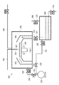
- FIG. 2 is a schematic configuration diagram for explaining an example of a suitable manufacturing system for embodying the present invention.
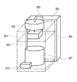
- FIG. 3 is a schematic configuration diagram of a part of the production line shown in FIG. 2.
- FIG. 4 is a schematic explanatory view for explaining a preferred configuration of a processing (medicine) liquid supply system provided in the medicine basket 302.
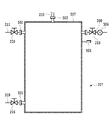
- FIG. 5 is a schematic configuration diagram of the vacuum waste liquid collector 207.
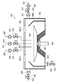
- FIG. 6 is a schematic configuration diagram for explaining another preferable processing chamber.
- FIG. 7 is a schematic top view for explaining the arrangement and ejection direction of nitrogen (N 2 ) gas ejection ports provided on the inner wall surface of the processing chamber 501 in FIG. 6.
- FIG. 8 is a graph showing a saturated vapor pressure curve of water.
- FIG. 1 is a schematic explanatory diagram for explaining a situation in which bubbles exist in a narrow and deep hole (hole) provided in an SOI substrate and the processing liquid does not penetrate to the bottom of the hole.
- reference numeral 100 is an SOI substrate
- 101 is a Si (silicon) semiconductor substrate
- 102 is a SiO 2 (silicon oxide) layer
- 103 is a Si layer (103-1, 103-2)
- 104 is a hole
- 105 is a bubble.
- 106 is a treatment liquid
- 107 is a gas-liquid interface
- 108 is an inner wall surface (108-1, 108-2)
- 109 is an inner bottom wall surface
- 110 is an opening.
- the so-called aspect ratio is represented by “l / r”.
- the conditions under which the bubbles 105 are formed in the holes 104 are the surface tension, viscosity, liquid composition, surface smoothness of the side wall surface 108, wettability of the processing liquid used, and the size and aspect of “r” and “l”. There are many parameters such as ratio, and it is difficult to discuss them in general.
- the inventors first formed various holes in the SOI substrate of the structural material as shown in FIG. 1 without limiting the inner structure of the hole 104 to a cylinder, and formed bubbles by using ultrapure water as a treatment liquid. I tried to verify the trend.
- the inner structure of the hole 104 is not limited to a cylindrical shape, but is a purse shape (the lower part of the opening extends in a bag shape or a tapered shape), a rectangular shape (a square shape such as a square, rectangle, or rhombus opening), a triangular shape It was created in various sizes as hexagonal, elliptical, super-elliptical, and star-shaped.
- the SiO 2 layer 102 constituting the inner bottom wall surface 109 was etched using hydrofluoric acid and buffered hydrofluoric acid, respectively, instead of ultrapure water.
- hydrofluoric acid even when the value of “V / S” was near “3”, the formation of bubbles was relatively small (the value of 300 holes with the value of “V / S” being “3”). Among them, about 15 bubbles were formed), but in the case of buffered hydrofluoric acid, bubbles were formed at a rate of 80% (240), and etching was not sufficient. Therefore, the present inventors performed the above-mentioned verification under a reduced pressure (30 Torr) by preparing a processing chamber capable of reducing the pressure.
- the inner space of the hall is hereinafter referred to as “micro vacancy”.
- the value of “r” in the case of a structure in which the micro vacancy is not a cylinder is based on the non-cylindrical “S” by regarding the micro vacancy as a cylinder.
- “l” is a depth (maximum depth) from the position of the opening to the position of the inner wall surface of the back of the micro-vacancy.
- the effect of reduced pressure in the present invention is that the aspect ratio (l / r) is 5 or more, or the aspect ratio is less than 5 and V / S (V: volume of micro-vacancy, S: area of opening) is 3 or more. Become noticeable in the case.
- the treatment liquid is buffered hydrofluoric acid and the object to be treated is an SOI substrate, a more remarkable effect can be obtained.
- FIG. 2 is a schematic configuration diagram for explaining an example of a suitable manufacturing system for embodying the present invention.
- FIG. 3 is a schematic configuration diagram of a part of the production line shown in FIG. 2 and 3, reference numeral 200 denotes a processing system, 201 denotes a decompression processing chamber (chamber), 202 denotes a target object installation table, 202-1 denotes a rotating shaft for the target object installation table, 203 denotes a target object, 204 Is an atmosphere gas supply line, 205 is a processing (chemical) liquid supply line, 206 is a recovery hood, 207 is a vacuum waste liquid tank, 208 is an air or N 2 supply line, 209 is a drainage line, 210 is a recovery line, 211,212 Is an exhaust line, 213 is an exhaust pump, 214 to 221 are valve, 222 is a supply amount variable nozzle for processing liquid, 301 is a spinner, 302 is a cartridge case, and 303 is an aluminum frame.
- 200 de
- the processing system 200 includes a reduced-pressure processing chamber (room) 201 and a reduced-pressure waste liquid tank 207, and the inside thereof is configured to be depressurized to a predetermined value by an exhaust pump 213.
- An atmosphere gas such as N 2 is supplied to the decompression processing chamber 201 from the outside via an atmosphere gas supply line 204, and a processing (chemical) solution is supplied to the decompression processing chamber 201 via a processing liquid supply line 205. They are supplied in fixed quantities.
- an open / close valve having a flow rate adjusting function is provided in the reduced pressure processing chamber 201.
- a target object installation table 202 is fixed and installed on a rotary shaft 201-1 for the target object installation table.
- a target object 203 is installed on the target object installation table 202.
- the atmospheric gas supplied into the reduced pressure processing chamber 201 via the atmospheric gas supply line 204 is indicated by an arrow B
- the treatment supplied via the recovery liquid 206 via the treatment liquid supply line 205 is indicated by an arrow B, as indicated by an arrow A.
- each is recovered from the recovery line 210 into the vacuum waste liquid tank 207 through the recovery hood 206.
- An opening / closing valve 217 is provided in the middle of the recovery line 210.
- a supply line 208 and an exhaust line 211 are coupled to the vacuum waste liquid tank 207.
- Supply line 208 is a supply line for atmospheric or N 2.
- the waste liquid 223 in the vacuum waste liquid tank 207 is discharged out of the vacuum waste liquid tank 207 through the drain line 209.
- the vacuum waste liquid tank 207 can be returned to atmospheric pressure by supplying air or N 2 from the supply line 208 as necessary.
- An open / close valve 215 is provided in the supply line 208.
- An opening / closing valve 216 is provided in the middle of the drain line 209.
- the decompression processing chamber 201 is decompressed by the pump 213 via the exhaust line 212 and the waste liquid tank 207 is decompressed by the pump 213.
- Valves 218 and 219 are installed in the middle of the exhaust line 211, and valves 220 and 221 are installed in the middle of the exhaust line 212, respectively.
- the valves 219 and 221 are open / close valves provided with a flow rate variable mechanism.
- the exhaust pump 213 is a moisture-resistant pump.
- a diaphragm type chemical dry vacuum pump specifically, DTC-120 (manufactured by ULVAC) is preferably employed.
- the processing chamber 201 and the waste liquid tank 207 are attached to, for example, an aluminum frame 303 as shown in FIG.
- a spinner 301 provided for rotating the rotary shaft 202-1 is also attached to the frame 303.
- a chemical basket 302 in which processing liquid is stored is connected to the upstream end of the processing (chemical) liquid supply line 205.
- FIG. 4 is a schematic explanatory diagram for explaining a preferred configuration of a processing (medicine) solution supply system provided inside the cartridge case 302.
- 400 is a nitrogen pressure feed process (chemical) liquid supply system
- 401 is a canister
- 402 is a process liquid supply line
- 403 and 411 are stop valves
- 404 is a flow control valve
- 405 is a flow meter
- 406 is a mist trap.
- 407 and 408 are nitrogen gas supply lines
- 409 is a vent (exhaust) valve
- 410 is a shunt joint
- 412 is a regulator
- 413 is a joint
- 414 and 415 are quick connectors.
- a processing (chemical) supply system 400 using a nitrogen pressure feeding system has a processing liquid supply line 402 in which a canister 401 is provided with a 3/8 inch line on the upstream side and a 1/4 inch line on the downstream side via a joint 413. Are connected to each other via a quick connector 414 and a 1/4 inch nitrogen gas supply line 407 via a quick connector 415.
- a stop valve 403, a flow rate adjustment valve 404, and a flow meter 405 are provided in the middle of the processing liquid supply line 402, a stop valve 403, a flow rate adjustment valve 404, and a flow meter 405 are provided.
- the downstream portion of the processing liquid supply line 402 on the stop valve 403 side is connected to the processing liquid supply line 205.
- a vent (exhaust) valve 409 and a diversion joint 410 are provided in the middle of the nitrogen gas supply line 407.
- the vent (exhaust) valve 409 is for exhausting the nitrogen gas in the canister 401 and the nitrogen gas supply line 407 to the outside.
- the downstream side of the nitrogen gas supply line 407 is inserted into the mist trap 406.
- Nitrogen gas is introduced into the mist trap 406 through the regulator 412, the stop valve 411, and the nitrogen gas supply line 408.
- the mist trap 406 is provided to prevent the processing liquid from flowing back to the upstream side.
- FIG. 5 is a schematic configuration diagram of the vacuum waste liquid tank 207.
- 501 is a drain flange
- 502 is a decompression flange
- 503 is a waste liquid introduction flange
- 504 is a gas introduction flange
- 505 is a vacuum gauge
- 506 is a flow meter
- 507 is a liquid level. An observation window is shown.
- the vacuum waste liquid tank 207 includes a drain line 209 via a drain flange 501, a drain line 211 via a vacuum flange 502, and a recovery line 210 via a waste liquid introduction flange 503.
- a supply line 208 is connected via 504.
- the vacuum gauge 505 measures the pressure in the waste liquid tank 207.
- a liquid level observation window 504 made of a transparent member for waste liquid is provided in order to observe the water level of the waste liquid in the waste liquid tank 207.
- FIG. 6 is a schematic configuration diagram for explaining another suitable processing chamber.
- 600 is a decompression processing chamber
- 601 is a chamber structure
- 602 is an upper lid
- 603 is a stage for setting the object to be processed
- 604 is a rotating shaft body
- 605 is a magnetic fluid seal
- 606 is a special processing (medicine) solution.
- 607 is ozone water supply line
- 608 is ultrapure water supply line
- 609, 610, 611 and 618 are flowmeters
- 612, 613, 614, 617, 621 and 624 are valves
- 615 is a gas introduction line
- 616, 620 and 623 are flanges
- 622 is a waste liquid line
- 625 is an observation window (625-1 and 625-2)
- 626 is a vacuum gauge.
- the vacuum processing chamber 600 shown in FIG. 6 is different from the vacuum processing chamber 201 shown in FIG. 2 in that three supplies of a special processing (chemical) liquid supply line 606, an ozone water supply line 607, and an ultrapure water supply line 608 are provided. It has a line. The rest is basically the same as the reduced pressure processing chamber 201 except for another difference. Another difference is that a gas introduction line 615 and a gas discharge line 619 are attached to the decompression processing chamber 600. The atmospheric gas in the reduced pressure processing chamber 600 is introduced through the gas introduction line 615. The gas introduction line 615 is attached to the vacuum processing chamber 600 by a flange 616. An opening / closing valve 617 and a flow meter 618 are provided in the middle of the gas introduction line 615.
- the gas discharge line 619 is attached to the decompression processing chamber 600 by a decompression flange 620.
- An opening / closing valve 621 is provided in the middle of the gas discharge line 615.
- a downstream side of the gas discharge line 615 is connected to a pump (not shown) similar to the vacuum pump 213.
- the decompression processing chamber 600 is configured such that the interior is maintained in a decompressed state by the chamber structure 601 and the upper lid 602.
- the upper lid 602 is provided with two observation windows 625-1 and 625-2 for observing the inside of the chamber 600.
- Inside the reduced pressure processing chamber 600 is provided a stage 603 for installing the target object on which the target object is set.
- a rotating shaft 604 for rotating the stage 603 is fixed to the stage 603 in a removable state.
- the rotating shaft body 604 is sealed with a magnetic fluid seal 605 and joined to a rotating shaft body of a spinner installed outside the decompression processing chamber 600.
- a flow meter 609 and a valve 612 are provided in the middle of the special processing (chemical) liquid supply line 606.
- a flow meter 610 and a valve 613 are provided in the middle of the ozone water supply line 607.
- a flow meter 611 and a valve 614 are provided in the middle of the ultrapure water supply line 608.
- a waste liquid line 622 is attached to the vacuum processing chamber 600 by a flange 623 at the bottom of the vacuum processing chamber 600.
- An opening / closing valve 624 is provided in the middle of the waste liquid line 622.
- a vacuum gauge 626 for measuring the pressure in the reduced pressure processing chamber 600 is attached to the side surface of the reduced pressure processing chamber 600.
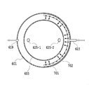
- FIG. 7 is a schematic top view for explaining the arrangement and ejection direction of nitrogen (N 2 ) gas ejection ports provided on the inner wall surface of the processing chamber 601 in FIG.
- reference numeral 701 denotes a gas jet inner wall pipe
- 702 denotes a gas jet outlet.
- a gas ejection inner wall pipe 701 coupled to the gas introduction line 615 is attached to the inner wall of the decompression processing chamber 600.
- the gas ejection inner wall pipe 701 is provided with a predetermined number of gas ejection ports 702 whose ejection direction is directed to the central axis of the inner space of the decompression processing chamber 600.
- the ejection diameter and the number of the gas ejection ports 702 are designed to be a predetermined gas ejection flow rate.
- the gas jetting (blowing) flow rate from the gas jetting port 702 is determined in advance at the time of design so as not to cause a stirring action or a turbulent action in the processing chamber as much as possible by the gas jetting. It is desirable to determine the optimum value in the preliminary experiment of gas ejection.
- the degree of stirring action or turbulent action due to gas ejection depends on the gas exhaust speed, and in the present invention, preferably 0.1 to 5.0 m / sec, more preferably 0.5 to 3.0 m. / sec, optimally around 2.0 m / sec.
- N 2 gas For example, when 20 nozzle holes 702 having a diameter of 2 mm are provided on the semicircular circumference as shown in the drawing, it is desirable to flow N 2 gas into the reduced pressure processing chamber 600 at an amount of 200 cc / min. At this time, the flow rate of the N 2 gas is 2.0 m / sec.
- the treatment liquid is sufficiently deaerated beforehand in order to enhance the gas absorption ability.
- N 2 gas or atmospheric gas has been exemplified as the atmospheric gas. However, if CO 2 gas is used instead of these gases, the amount dissolved in the treatment liquid can be reduced. Since it can increase, it is preferable.
- FIG. 8 is a graph showing a saturated vapor pressure curve of water.
- the horizontal axis indicates temperature (° C.), and the vertical axis indicates pressure (Torr).
- the processing solution is introduced while reducing the pressure in the processing chamber.
- the degree of the pressure reduction is preferably set to 30 Torr in order to avoid boiling of the processing solution. If pressure is applied after supplying the treatment liquid onto the surface of the substrate to be treated under reduced pressure, even if bubbles remain in the tail hole, it is desirable because the volume of the bubble is reduced by pressurization and easily escapes from the hole. For example, when the pressure is reduced from 30 Torr to 760 Torr, the volume of the bubbles becomes about 1/25. Therefore, in the present invention, it is also a preferable aspect to reduce the pressure and supply the treatment liquid sufficiently and then pressurize. Furthermore, this decompression and pressurization may occur repeatedly.
- the technology of the present invention is not limited to TSV, and can be applied to technical fields such as MEMS as long as it requires a high aspect ratio hole. .
- SYMBOLS 100 SOI substrate 101 ... Si (silicon) semiconductor substrate 102 ... SiO2 (silicon oxide) layer 103 ... Si layer (103-1, 103-2) 104 ... Hole 105 ... Bubble 106 ... Processing liquid 107 ... Gas-liquid interface 108 ... Inner wall surface (108-1, 108-2) 109 ... inner bottom wall surface 110 ... opening 200 ... treatment system 201 ... decompression treatment chamber (room) 202 ... Object to be processed installation table 202-1 ... Rotating shaft 203 for object to be processed installation table ... Object to be processed 204 ... Atmospheric gas supply line 205 ... Process (chemical) liquid supply Line 206 ... Recovery hood 207 ...
- Depressurized waste liquid tank 208 ... Atmosphere or N2 supply line 209 ... Drain line 210 ... Recovery lines 211, 212 ... Exhaust line 213 ... Exhaust pump 214, 215, 216, 217, 218, 219, 220, 221 ... Valp 222 ... Supply amount variable nozzle 301 for processing liquid ... Spinner 302 ... Powder bowl 303 ... Aluminum frame 400 ... ⁇ Nitrogen pressure feed processing (chemical) liquid supply system 401... Canister 402... Processing liquid supply line 403, 411. Node valve 405 ... Flow meter 406 ... Mist trap 407, 408 ... Nitrogen gas supply line 409 ... Vent (exhaust) valve 410 ... Split flow joint 412 ...
- Valve 615 Gas introduction line 619 ... Gas discharge lines 616, 620, 623 ... Flange 622 ..Waste liquid line 625 ... Observation windows (625-1, 625-2) 626 ... Vacuum gauge 701 ... Gas ejection inner wall tube 702 ... Gas ejection port
Landscapes
- Cleaning Or Drying Semiconductors (AREA)
Abstract
Description
しかし、その基本技術の一つである露光技術の停滞により、微細化による高集積化に限界説が云われ始めている。また、基本電子素子の微細化はLSIデバイス化した際のデバイスの温度上昇や電子漏洩の潜在的問題もある。最近は、微細化に依らない高集積化の技術開発もされ始めている。その一つがLSIの3次元化(3DI:3 Dimensional Integration)の技術である。この技術の実現に必要な技術の一つが、TSV(Through Silicon Via)の技術である。この技術を用いた3D集積化LSIデバイスは、ワイヤーボンディング技術を用いるパッケージレベルの3D集積化デバイスとは異なり、集積している一つ一つのデバイス間の電気的相互接続特性の飛躍的向上も期待され、次世代の高集積化デバイスとして有力である。
101・・・Si(シリコン)半導体基板
102・・・SiO2(酸化シリコン)層
103・・・Si層(103-1,103-2)
104・・・ホール
105・・・気泡
106・・・処理液
107・・・気液界面
108・・・内側壁面(108-1,108-2)
109・・・内底壁面
110・・・開口
200・・・処理システム
201・・・減圧処理チャンバー(室)
202・・・被処理体設置テーブル
202-1・・・被処理体設置テーブル用の回転軸体
203・・・被処理体
204・・・雰囲気ガス供給ライン
205・・・処理(薬)液供給ライン
206・・・回収フード
207・・・減圧廃液タンク
208・・・大気若しくはN2供給ライン
209・・・排液ライン
210・・・回収ライン
211、212・・・排気ライン
213・・・排気ポンプ
214、215,216,217,218,219,220、221・・・バルプ
222・・・処理液用の供給量可変ノズル
301・・・スピナー
302・・・薬莢
303・・・アルミフレーム
400・・・窒素圧送方式処理(薬)液供給系
401・・・キャニスター
402・・・処理液供給ライン
403、411・・・ストップバルブ
404・・・流量調節バルブ
405・・・流量計
406・・・ミストトラップ
407、408・・・窒素ガス供給ライン
409・・・ベント(排気)バルブ
410・・・分流継手
412・・・レギュレーター
413・・・継手
414、415・・・クイックコネクター
501・・・ドレイン用のフランジ
502・・・減圧用のフランジ
503・・・廃液導入用のフランジ
504・・・ガス導入用のフランジ
505・・・真空計
506・・・流量計
507・・・液位観察用窓
600・・・減圧処理チャンバー
601・・・チャンバー構成体
602・・・上蓋
603・・・被処理体設置用のステージ
604・・・回転軸体
605・・・磁性流体シール
606・・・特殊処理(薬)液供給ライン
607・・・オゾン水供給ライン
608・・・超純水供給ライン
609,610,611,618・・・流量計
612,613,614、617、621,624・・・バルブ
615・・・ガス導入ライン
619・・・ガス排出ライン
616、620、623・・・フランジ
622・・・廃液ライン
625・・・観察用窓(625-1,625-2)
626・・・真空計
701・・・ガス噴出内壁管
702・・・ガス噴出口
Claims (1)
- 処理液が付与される表面と該表面に開口を有するマイクロ空室を内部に有し、該マイクロ空室のアスペクト比(l/r)が5以上かまたはアスペクト比が5未満でかつV/S(V: マイクロ空室の容積、S:開口の面積)が3以上である基体が設置さている減圧可能な処理空間を減圧し、次いで該減圧されている処理空間に前記処理液を導入して前記マイクロ空室の内壁面を処理することを特徴とするマイクロ空室の内壁面処理方法。
Priority Applications (5)
| Application Number | Priority Date | Filing Date | Title |
|---|---|---|---|
| KR1020157030067A KR20150136499A (ko) | 2013-04-18 | 2013-04-18 | 마이크로 공실의 내벽면 처리방법 |
| US14/784,725 US20160064213A1 (en) | 2013-04-18 | 2013-04-18 | Method for treating inner wall surface of micro-vacancy |
| PCT/JP2013/002645 WO2014170928A1 (ja) | 2013-04-18 | 2013-04-18 | マイクロ空室の内壁面処理方法 |
| CN201380075653.XA CN105122425A (zh) | 2013-04-18 | 2013-04-18 | 微空腔的内壁面处理方法 |
| JP2013544915A JP5549026B1 (ja) | 2013-04-18 | 2013-04-18 | マイクロ空室の内壁面処理方法 |
Applications Claiming Priority (1)
| Application Number | Priority Date | Filing Date | Title |
|---|---|---|---|
| PCT/JP2013/002645 WO2014170928A1 (ja) | 2013-04-18 | 2013-04-18 | マイクロ空室の内壁面処理方法 |
Publications (1)
| Publication Number | Publication Date |
|---|---|
| WO2014170928A1 true WO2014170928A1 (ja) | 2014-10-23 |
Family
ID=51416752
Family Applications (1)
| Application Number | Title | Priority Date | Filing Date |
|---|---|---|---|
| PCT/JP2013/002645 Ceased WO2014170928A1 (ja) | 2013-04-18 | 2013-04-18 | マイクロ空室の内壁面処理方法 |
Country Status (5)
| Country | Link |
|---|---|
| US (1) | US20160064213A1 (ja) |
| JP (1) | JP5549026B1 (ja) |
| KR (1) | KR20150136499A (ja) |
| CN (1) | CN105122425A (ja) |
| WO (1) | WO2014170928A1 (ja) |
Cited By (4)
| Publication number | Priority date | Publication date | Assignee | Title |
|---|---|---|---|---|
| NL2014598A (en) * | 2015-04-08 | 2016-10-12 | Suss Microtec Lithography Gmbh | Method for coating a substrate. |
| JP2020505778A (ja) * | 2017-01-27 | 2020-02-20 | ティーイーエル エフエスアイ,インコーポレイティド | 基板をプロセスチャンバ内で回転及び並進するためのシステム及び方法 |
| US11476129B2 (en) | 2016-11-29 | 2022-10-18 | Tel Manufacturing And Engineering Of America, Inc. | Translating and rotating chuck for processing microelectronic substrates in a process chamber |
| US11545387B2 (en) | 2018-07-13 | 2023-01-03 | Tel Manufacturing And Engineering Of America, Inc. | Magnetic integrated lift pin system for a chemical processing chamber |
Families Citing this family (4)
| Publication number | Priority date | Publication date | Assignee | Title |
|---|---|---|---|---|
| CN105374742B (zh) * | 2014-09-02 | 2019-03-12 | 中芯国际集成电路制造(上海)有限公司 | 半导体结构的形成方法 |
| JP6685197B2 (ja) * | 2016-07-26 | 2020-04-22 | 東京エレクトロン株式会社 | 基板処理装置およびノズル |
| KR102400186B1 (ko) * | 2017-06-19 | 2022-05-20 | 삼성전자주식회사 | 공정 챔버 및 이를 포함하는 기판 처리 장치 |
| JP2021034561A (ja) * | 2019-08-23 | 2021-03-01 | キオクシア株式会社 | 半導体製造装置 |
Citations (2)
| Publication number | Priority date | Publication date | Assignee | Title |
|---|---|---|---|---|
| JPH0444322A (ja) * | 1990-06-11 | 1992-02-14 | Mitsubishi Electric Corp | 半導体装置の製造方法 |
| JPH09275085A (ja) * | 1996-04-05 | 1997-10-21 | Hitachi Ltd | 半導体基板の洗浄方法ならびに洗浄装置および半導体基板製造用成膜方法および成膜装置 |
Family Cites Families (9)
| Publication number | Priority date | Publication date | Assignee | Title |
|---|---|---|---|---|
| JPH0795541B2 (ja) * | 1986-07-02 | 1995-10-11 | 松下電器産業株式会社 | 処理方法 |
| US5368634A (en) * | 1993-07-26 | 1994-11-29 | Hughes Aircraft Company | Removing bubbles from small cavities |
| US5966631A (en) * | 1997-10-03 | 1999-10-12 | International Business Machines Corporation | Forced plug processing for high aspect ratio structures |
| US7125809B1 (en) * | 2000-08-31 | 2006-10-24 | Micron Technology, Inc. | Method and material for removing etch residue from high aspect ratio contact surfaces |
| US7935571B2 (en) * | 2008-11-25 | 2011-05-03 | Freescale Semiconductor, Inc. | Through substrate vias for back-side interconnections on very thin semiconductor wafers |
| JP5201048B2 (ja) * | 2009-03-25 | 2013-06-05 | 富士通株式会社 | 半導体装置とその製造方法 |
| US20120102778A1 (en) * | 2010-04-22 | 2012-05-03 | Ismail Kashkoush | Method of priming and drying substrates |
| JP5278492B2 (ja) * | 2010-06-16 | 2013-09-04 | 株式会社デンソー | 半導体装置の製造方法 |
| CN108435679A (zh) * | 2012-04-17 | 2018-08-24 | 普莱克斯技术有限公司 | 用于将纯化多相二氧化碳输送至处理工具的系统 |
-
2013
- 2013-04-18 JP JP2013544915A patent/JP5549026B1/ja not_active Expired - Fee Related
- 2013-04-18 WO PCT/JP2013/002645 patent/WO2014170928A1/ja not_active Ceased
- 2013-04-18 US US14/784,725 patent/US20160064213A1/en not_active Abandoned
- 2013-04-18 KR KR1020157030067A patent/KR20150136499A/ko not_active Ceased
- 2013-04-18 CN CN201380075653.XA patent/CN105122425A/zh active Pending
Patent Citations (2)
| Publication number | Priority date | Publication date | Assignee | Title |
|---|---|---|---|---|
| JPH0444322A (ja) * | 1990-06-11 | 1992-02-14 | Mitsubishi Electric Corp | 半導体装置の製造方法 |
| JPH09275085A (ja) * | 1996-04-05 | 1997-10-21 | Hitachi Ltd | 半導体基板の洗浄方法ならびに洗浄装置および半導体基板製造用成膜方法および成膜装置 |
Cited By (9)
| Publication number | Priority date | Publication date | Assignee | Title |
|---|---|---|---|---|
| NL2014598A (en) * | 2015-04-08 | 2016-10-12 | Suss Microtec Lithography Gmbh | Method for coating a substrate. |
| US9799554B2 (en) | 2015-04-08 | 2017-10-24 | Suss Microtec Lithography Gmbh | Method for coating a substrate |
| AT516988A3 (de) * | 2015-04-08 | 2018-04-15 | Suss Microtec Lithography Gmbh | Verfahren zum Beschichten eines Substrats |
| AT516988B1 (de) * | 2015-04-08 | 2022-10-15 | Suss Microtec Lithography Gmbh | Verfahren zum Beschichten eines Substrats |
| US11476129B2 (en) | 2016-11-29 | 2022-10-18 | Tel Manufacturing And Engineering Of America, Inc. | Translating and rotating chuck for processing microelectronic substrates in a process chamber |
| JP2020505778A (ja) * | 2017-01-27 | 2020-02-20 | ティーイーエル エフエスアイ,インコーポレイティド | 基板をプロセスチャンバ内で回転及び並進するためのシステム及び方法 |
| US11458512B2 (en) | 2017-01-27 | 2022-10-04 | Tel Manufacturing And Engineering Of America, Inc. | Systems and methods for rotating and translating a substrate in a process chamber |
| JP7177069B2 (ja) | 2017-01-27 | 2022-11-22 | ティーイーエル マニュファクチュアリング アンド エンジニアリング オブ アメリカ,インコーポレイテッド | 基板をプロセスチャンバ内で回転及び並進するためのシステム及び方法 |
| US11545387B2 (en) | 2018-07-13 | 2023-01-03 | Tel Manufacturing And Engineering Of America, Inc. | Magnetic integrated lift pin system for a chemical processing chamber |
Also Published As
| Publication number | Publication date |
|---|---|
| JPWO2014170928A1 (ja) | 2017-02-16 |
| CN105122425A (zh) | 2015-12-02 |
| JP5549026B1 (ja) | 2014-07-16 |
| KR20150136499A (ko) | 2015-12-07 |
| US20160064213A1 (en) | 2016-03-03 |
Similar Documents
| Publication | Publication Date | Title |
|---|---|---|
| JP5549026B1 (ja) | マイクロ空室の内壁面処理方法 | |
| TWI405622B (zh) | 超音波清洗流體、方法及設備 | |
| JP5695833B2 (ja) | ダメージを低減した物理力アシスト洗浄方法 | |
| JP2008300429A (ja) | 半導体基板洗浄方法、半導体基板洗浄装置、及び液中気泡混合装置 | |
| TWI680016B (zh) | 基板處理方法以及基板處理裝置 | |
| JP5569831B1 (ja) | マイクロ空室の内壁面処理方法 | |
| JP7258915B2 (ja) | 半導体ウエハの洗浄に用いられる方法及び装置 | |
| JP2012209299A (ja) | 基板処理方法および基板処理装置 | |
| JP2006147617A (ja) | 基板処理装置およびパーティクル除去方法 | |
| JP4482844B2 (ja) | ウェハの洗浄方法 | |
| JP2014212299A (ja) | マイクロ空室の内壁面処理方法 | |
| JP6243802B2 (ja) | デバイスの製造方法 | |
| JP5561811B1 (ja) | エッチング方法及びlsiデバイスの製造方法、並びに3d集積化lsiデバイス製造方法 | |
| TWI487022B (zh) | Method of treating inner wall of fine pores | |
| JP7423980B2 (ja) | ウエハの表面の洗浄装置及びウエハの表面の洗浄方法 | |
| TWI567810B (zh) | The method of making the inner wall surface of the micro chamber and the manufacturing method of the component | |
| TW201448022A (zh) | 微細空孔之內壁面處理方法 | |
| TWI610355B (zh) | 微空室之內壁面處理方法及元件之製造方法 | |
| WO2010097896A1 (ja) | 洗浄用ノズル及び洗浄方法 | |
| JP7373492B2 (ja) | 基板の洗浄方法及び洗浄装置 | |
| Suzuki et al. | Application of novel ultrasonic cleaning equipment that uses the waveguide mode for the single-wafer cleaning process | |
| JP6020626B2 (ja) | デバイス用Ge基板の洗浄方法、洗浄水供給装置及び洗浄装置 | |
| KR101987709B1 (ko) | 사류체 노즐 | |
| JP2003147576A (ja) | めっき装置及びめっき方法 | |
| JP2017117860A (ja) | 基板洗浄方法および基板洗浄装置 |
Legal Events
| Date | Code | Title | Description |
|---|---|---|---|
| ENP | Entry into the national phase |
Ref document number: 2013544915 Country of ref document: JP Kind code of ref document: A |
|
| 121 | Ep: the epo has been informed by wipo that ep was designated in this application |
Ref document number: 13882486 Country of ref document: EP Kind code of ref document: A1 |
|
| WWE | Wipo information: entry into national phase |
Ref document number: 14784725 Country of ref document: US |
|
| ENP | Entry into the national phase |
Ref document number: 20157030067 Country of ref document: KR Kind code of ref document: A |
|
| NENP | Non-entry into the national phase |
Ref country code: DE |
|
| 122 | Ep: pct application non-entry in european phase |
Ref document number: 13882486 Country of ref document: EP Kind code of ref document: A1 |