WO2014168201A1 - 被覆光ファイバ - Google Patents
被覆光ファイバ Download PDFInfo
- Publication number
- WO2014168201A1 WO2014168201A1 PCT/JP2014/060394 JP2014060394W WO2014168201A1 WO 2014168201 A1 WO2014168201 A1 WO 2014168201A1 JP 2014060394 W JP2014060394 W JP 2014060394W WO 2014168201 A1 WO2014168201 A1 WO 2014168201A1
- Authority
- WO
- WIPO (PCT)
- Prior art keywords
- coating layer
- optical fiber
- meth
- coated optical
- primary coating
- Prior art date
- Legal status (The legal status is an assumption and is not a legal conclusion. Google has not performed a legal analysis and makes no representation as to the accuracy of the status listed.)
- Ceased
Links
Images

Classifications
-
- G—PHYSICS
- G02—OPTICS
- G02B—OPTICAL ELEMENTS, SYSTEMS OR APPARATUS
- G02B6/00—Light guides; Structural details of arrangements comprising light guides and other optical elements, e.g. couplings
- G02B6/02—Optical fibres with cladding with or without a coating
- G02B6/036—Optical fibres with cladding with or without a coating core or cladding comprising multiple layers
- G02B6/03694—Multiple layers differing in properties other than the refractive index, e.g. attenuation, diffusion, stress properties
-
- C—CHEMISTRY; METALLURGY
- C03—GLASS; MINERAL OR SLAG WOOL
- C03C—CHEMICAL COMPOSITION OF GLASSES, GLAZES OR VITREOUS ENAMELS; SURFACE TREATMENT OF GLASS; SURFACE TREATMENT OF FIBRES OR FILAMENTS MADE FROM GLASS, MINERALS OR SLAGS; JOINING GLASS TO GLASS OR OTHER MATERIALS
- C03C25/00—Surface treatment of fibres or filaments made from glass, minerals or slags
- C03C25/10—Coating
- C03C25/104—Coating to obtain optical fibres
- C03C25/1065—Multiple coatings
-
- C—CHEMISTRY; METALLURGY
- C03—GLASS; MINERAL OR SLAG WOOL
- C03C—CHEMICAL COMPOSITION OF GLASSES, GLAZES OR VITREOUS ENAMELS; SURFACE TREATMENT OF GLASS; SURFACE TREATMENT OF FIBRES OR FILAMENTS MADE FROM GLASS, MINERALS OR SLAGS; JOINING GLASS TO GLASS OR OTHER MATERIALS
- C03C25/00—Surface treatment of fibres or filaments made from glass, minerals or slags
- C03C25/10—Coating
- C03C25/24—Coatings containing organic materials
-
- C—CHEMISTRY; METALLURGY
- C03—GLASS; MINERAL OR SLAG WOOL
- C03C—CHEMICAL COMPOSITION OF GLASSES, GLAZES OR VITREOUS ENAMELS; SURFACE TREATMENT OF GLASS; SURFACE TREATMENT OF FIBRES OR FILAMENTS MADE FROM GLASS, MINERALS OR SLAGS; JOINING GLASS TO GLASS OR OTHER MATERIALS
- C03C25/00—Surface treatment of fibres or filaments made from glass, minerals or slags
- C03C25/10—Coating
- C03C25/24—Coatings containing organic materials
- C03C25/26—Macromolecular compounds or prepolymers
- C03C25/28—Macromolecular compounds or prepolymers obtained by reactions involving only carbon-to-carbon unsaturated bonds
- C03C25/285—Acrylic resins
-
- C—CHEMISTRY; METALLURGY
- C03—GLASS; MINERAL OR SLAG WOOL
- C03C—CHEMICAL COMPOSITION OF GLASSES, GLAZES OR VITREOUS ENAMELS; SURFACE TREATMENT OF GLASS; SURFACE TREATMENT OF FIBRES OR FILAMENTS MADE FROM GLASS, MINERALS OR SLAGS; JOINING GLASS TO GLASS OR OTHER MATERIALS
- C03C25/00—Surface treatment of fibres or filaments made from glass, minerals or slags
- C03C25/10—Coating
- C03C25/24—Coatings containing organic materials
- C03C25/26—Macromolecular compounds or prepolymers
- C03C25/32—Macromolecular compounds or prepolymers obtained otherwise than by reactions involving only carbon-to-carbon unsaturated bonds
- C03C25/326—Polyureas; Polyurethanes
-
- G—PHYSICS
- G02—OPTICS
- G02B—OPTICAL ELEMENTS, SYSTEMS OR APPARATUS
- G02B6/00—Light guides; Structural details of arrangements comprising light guides and other optical elements, e.g. couplings
- G02B6/02—Optical fibres with cladding with or without a coating
- G02B6/02395—Glass optical fibre with a protective coating, e.g. two layer polymer coating deposited directly on a silica cladding surface during fibre manufacture
Definitions
- the present invention relates to a coated optical fiber in which a primary coating layer and a secondary coating layer are provided on the outer periphery of the optical fiber.
- an optical fiber obtained by hot-melt spinning glass is coated with a resin for the purpose of protection and reinforcement.
- the coating resin is in a stable state after being cured, the residual stress or strain in the coating resin is reduced due to the stress or strain that is newly applied to the optical fiber during work such as rewinding or when the temperature changes.
- a transmission loss called microbend loss may occur.
- the primary coating that contacts the optical fiber is increased while increasing the Young's modulus of the secondary coating layer to increase the rigidity.
- a method for improving the microbend resistance property by reducing the Young's modulus of the layer and providing performance as a buffer material is known.
- Patent Document 1 relating to an optical fiber having anti-microbend resistance properties discloses that the Young's modulus of the primary coating layer is 0.55 MPa or less and the Young's modulus of the secondary coating layer is 500 to 1500 MPa.
- the coated optical fiber having the physical properties described in Patent Document 1 seems to have no problem at room temperature, but the transmission characteristics are expected to deteriorate at a low temperature. If the Young's modulus of the secondary coating layer is increased and the Young's modulus of the primary coating layer is decreased to improve the microbend resistance (to reduce the increase in transmission loss due to microbending), the primary coating layer becomes lower at low temperatures. The tensile stress received from the secondary coating layer increases, and cracks (voids) in the primary coating layer are likely to occur. If voids occur in the primary coating layer, the transmission characteristics of the optical fiber deteriorate.
- the present invention has been made in view of the above-described problems in conventional coated optical fibers, and the object of the present invention is to provide a coated optical fiber excellent in both microbend resistance and low temperature characteristics. It is.
- the present inventors have found that not only the Young's modulus but also the tin content of the primary coating layer is important for improving low-temperature characteristics, and optimizing this. As a result, both the anti-microbend resistance and the low temperature characteristics can be achieved, and the present invention has been completed.
- the present invention is as follows.
- An optical fiber in which a clad layer made of glass is formed on the outer periphery of a glass core, a primary coating layer that covers the outer periphery of the optical fiber, and a coating that has a secondary coating layer that covers the outer periphery of the primary coating layer An optical fiber, wherein the Young's modulus of the primary coating layer is 1.2 MPa or less, the Young's modulus of the secondary coating layer is 700 MPa or more, and the tin content in the primary coating layer is 70 ppm or less.
- the primary coating layer is formed of an ultraviolet curable resin composition containing at least one acylphosphine oxide photopolymerization reaction initiator, and the secondary coating layer is at least one type. Any one of [1] to [6], which is formed of an ultraviolet curable resin composition containing an acylphosphine oxide-based photopolymerization reaction initiator and an ⁇ -hydroxyacetophenone type photopolymerization initiator.
- the coated optical fiber as described.
- [8] The coated optical fiber according to [7], wherein the amount of unreacted acylphosphine oxide photopolymerization initiator in the coating layer is 0.5% by mass or less.
- (meth) acryloyl group-containing A) primary coating layer obtained by reacting (A) aliphatic polyol having a molecular weight of 3500 or less, organic polyisocyanate, hydroxyl group-containing (meth) acrylate and ⁇ -mercaptopropyltrimethoxysilane Urethane oligomers; (B) a reactive diluent having a glass transition temperature of 0 ° C. or lower when polymerized with at least one simple substance; and (C) The coated optical fiber according to any one of [1] to [8], which is formed of an ultraviolet curable coating agent containing a photopolymerization reaction initiator.
- both the microbend resistance property and the low temperature property are excellent.
- a coated optical fiber can be provided.
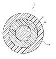
- FIG. 1 is a schematic cross-sectional view showing an example of the coated optical fiber of the present invention.
- the coated optical fiber 1 has a primary coating layer 20 formed by curing an ultraviolet curable resin composition on the outer periphery of the optical fiber 10 and a secondary coating layer 30 formed by curing a curable resin on the outer periphery thereof.
- a resin coating layer is formed by the two layers of the primary coating layer 20 and the secondary coating layer 30.
- the optical fiber 10 normally includes a cladding layer made of quartz glass on the outer periphery of a core layer made of quartz glass.
- the outer diameter of the core layer can be, for example, 7 ⁇ m to 60 ⁇ m, and the outer diameter of the cladding layer can be, for example, 125 ⁇ m.
- the primary coating layer 20 is a layer of a cured resin formed on the outer periphery of the optical fiber 10 and can have a thickness of 10 ⁇ m to 50 ⁇ m, for example.
- the secondary coating layer 30 is a cured resin layer formed on the outer periphery of the primary coating layer 20, and can have a thickness of 10 ⁇ m to 50 ⁇ m, for example.
- the thickness of the primary coating layer and the secondary coating layer may be substantially equal.
- the ratio of the two can be 5: 7 to 7: 5.
- These coating layers are formed by curing an ultraviolet curable resin composition.
- the ultraviolet curable resin composition include (A) urethane oligomer; (B) reactive diluent; and ( C) What contains a photoinitiator is mentioned.
- the ultraviolet curable resin composition may further contain (D) a surfactant.
- the Young's modulus of the primary coating layer is 1.2 MPa or less
- the Young's modulus of the secondary coating layer is 700 MPa or more
- the tin content in the primary coating layer is 70 ppm or less. Both characteristics were excellent.
- the Young's modulus of the primary coating layer is made smaller than before, but this increases transmission loss at low temperatures.
- the Young's modulus of the primary coating layer is made smaller than before (1.2 MPa or less), and the tin content in the coating layer (particularly the primary coating layer) is made smaller (70 ppm or less) than before. Both of the above characteristics are excellent.
- the optical fiber transmission characteristics at a low temperature are such that the effect of the primary coating layer close to glass is larger than the effect of the secondary coating layer, so that the tin content in the primary coating layer should be 70 ppm or less at low temperatures. It is effective in suppressing the increase of If the tin content of the combination of the primary coating layer, the secondary coating layer, and both layers (hereinafter also simply referred to as “coating layer”) is 70 ppm or less, it is effective for suppressing an increase in transmission loss at a lower temperature. .
- the Young's modulus of the primary coating layer is 0.2 MPa or more. It is preferable that As the Young's modulus of the secondary coating layer increases, the mechanical strength of the coated optical fiber tends to increase. However, if the Young's modulus of the secondary coating layer is too large, the optical fiber becomes stiff and difficult to handle. In this respect, the Young's modulus of the secondary coating layer is preferably 1500 MPa or less.
- the Young's modulus and tin content of the coating layer are measured by the following method.
- Primary coating Young's modulus measured by Pullout Modulus test at 23 ° C. Specifically, the coating layer of the optical fiber is cut with a razor or the like to cut the resin coating layer, the resin coating layer (primary coating layer and secondary coating layer) is fixed, and the glass fiber is drawn. The stress of the primary coating layer is determined from the amount by which the primary coating layer is elastically deformed before the glass fiber is pulled out and the force that pulled the glass fiber.
- Tin content in the coating layer calculated from ICP emission analysis. Specifically, 20 ml of sulfuric acid / 6 ml of nitric acid are added to 1 g of a sample and heated for 10 minutes. Then, 4 ml of perchloric acid is added and heated until there is no insoluble matter. Is measured with an emission analyzer using a light source. If the sample is only the primary coating layer or only the secondary coating layer, the tin content in each layer can be determined.
- a tin compound catalyst may be used in the production process of the ultraviolet curable resin such as urethane oligomer (A) contained in the ultraviolet curable resin composition forming the coating layer of the coated optical fiber of the present invention.
- the tin compound catalyst is mixed in.
- the (C) photopolymerization reaction initiator contained in the ultraviolet curable resin composition those containing phosphorus are preferably used because of the advantage of excellent curability.
- the tin component mixed in the urethane oligomer and (C) the phosphorus component contained in the photopolymerization initiator are reacted, and as a result, the coated optical fiber
- the tin content rate in a primary coating layer can be decreased by suppressing tin mixing of the (A) urethane oligomer of the said ultraviolet curable resin composition.
- the tin content rate in a primary coating layer is 50 ppm or less, and it is still more preferable that the total tin content rate of a primary coating layer and a secondary coating layer is 50 ppm or less.
- Both the primary coating layer and the secondary coating layer preferably have a tin content of 10 ppm or more. This is because it is preferable to add a small amount of a tin compound as a catalyst in view of the production efficiency of the ultraviolet curable resin composition.
- a suitable phosphorus containing initiator can be used as a (C) photopolymerization reaction initiator contained in the ultraviolet curable resin composition which forms a primary coating layer without concern.
- the components (A) to (D) contained in the ultraviolet curable resin composition forming the coating layer of the coated optical fiber of the present invention will be described in detail below.
- the urethane oligomer is not particularly limited as long as the mixing amount of the tin compound shows the tin content range of the coating layer defined in the present invention, but the (meth) acryloyl group which is a reactive group Reactive oligomers containing are preferred.
- Such a (meth) acryloyl group-containing urethane oligomer can be obtained, for example, by reacting an aliphatic polyether polyol, an organic polyisocyanate, a hydroxyl group-containing (meth) acrylate, and ⁇ -mercaptopropyltrimethoxysilane.
- the molecular weight is preferably about 5000 to 30000.
- the resin is cured by polymerizing (A) (meth) acryloyl group-containing urethane oligomer with (B) a reactive diluent which is a reactive monomer.
- the urethane oligomer is preferably contained in an amount of 60 to 80% by mass in the ultraviolet curable resin composition.
- the primary coating layer preferably satisfies the tin content range defined in the present invention.
- Examples of the aliphatic polyether-based polyol used in the synthesis reaction of the above (meth) acryloyl group-containing urethane oligomer include polyethylene glycol, polypropylene glycol, polytetramethylene glycol, polyhexamethylene glycol, polyheptamethylene glycol, polydecamethylene glycol. And polyether diol obtained by ring-opening copolymerization of two or more ion-polymerizable cyclic compounds.
- Examples of the ion polymerizable cyclic compound include ethylene oxide, propylene oxide, butene-1-oxide, isobutene oxide, 3,3-bischloromethyloxetane, tetrahydrofuran, 2-methyltetrahydrofuran, 3-methyltetrahydrofuran, dioxane, trioxane, tetraoxane, Cyclohexene oxide, styrene oxide, epichlorohydrin, glycidyl methacrylate, allyl glycidyl ether, allyl glycidyl carbonate, butadiene monooxide, isoprene monooxide, vinyl oxetane, vinyl tetrahydrofuran, vinyl cyclohexene oxide, phenyl glycidyl ether, butyl glycidyl ether, benzoic acid glycidyl ester, etc.
- polyether diols obtained by ring-opening copolymerization of two or more ion-polymerizable cyclic compounds include tetrahydrofuran and propylene oxide, tetrahydrofuran and 2-methyltetrahydrofuran, tetrahydrofuran and 3-methyltetrahydrofuran, tetrahydrofuran and ethylene oxide, and the like.
- Examples of the organic polyisocyanate used for the synthesis reaction of the above (meth) acryloyl group-containing urethane oligomer include aromatic diisocyanates, alicyclic diisocyanates, and aliphatic diisocyanates.
- aromatic diisocyanates include 2,4-tolylene diisocyanate, 2,6-tolylene diisocyanate, 1,3-xylylene diisocyanate, 1,4-xylylene diisocyanate, 1,5-naphthalene diisocyanate, and m-phenylene.
- Examples of the alicyclic diisocyanate include isophorone diisocyanate, methylenebis (4-cyclohexylisocyanate), hydrogenated diphenylmethane diisocyanate, hydrogenated xylylene diisocyanate, 2,5-bis (isocyanatemethyl) -bicyclo [2.2.1] heptane. 2,6-bis (isocyanatomethyl) -bicyclo [2.2.1] heptane and the like.
- Examples of the aliphatic diisocyanate include 1,6-hexane diisocyanate, 2,2,4-trimethylhexamethylene diisocyanate, and lysine diisocyanate.
- aromatic diisocyanate is more preferable, and 2,4-tolylene diisocyanate and 2,6-tolylene diisocyanate are particularly preferable from the viewpoint of obtaining an economical and stable quality composition.
- organic polyisocyanates may be used alone or in combination of two or more.
- hydroxyl group-containing (meth) acrylate used for the synthesis reaction of the above (meth) acryloyl group-containing urethane oligomer
- a hydroxyl group-containing (meth) acrylate having a hydroxyl group bonded to a primary carbon atom hereinafter referred to as “first hydroxyl group-containing (meth)”. It is preferable to use a hydroxyl group-containing (meth) acrylate having a hydroxyl group bonded to a secondary carbon atom (hereinafter also referred to as “secondary hydroxyl group-containing (meth) acrylate”).
- a hydroxyl group-containing (meth) acrylate having a hydroxyl group bonded to a tertiary carbon atom (hereinafter also referred to as “tertiary hydroxyl group-containing (meth) acrylate”) is not preferable because of its poor reactivity with an isocyanate group.
- tertiary hydroxyl group-containing (meth) acrylates include 2-hydroxyethyl (meth) acrylate, 3-hydroxypropyl (meth) acrylate, 4-hydroxybutyl (meth) acrylate, and 1,6-hexanediol mono (meth) acrylate.
- Pentaerythritol tri (meth) acrylate dipentaerythritol penta (meth) acrylate, neopentyl glycol mono (meth) acrylate, trimethylolpropane di (meth) acrylate, trimethylolethane di (meth) acrylate, and the like.
- secondary hydroxyl group-containing (meth) acrylates examples include 2-hydroxypropyl (meth) acrylate, 2-hydroxybutyl (meth) acrylate, 2-hydroxy-3-phenyloxypropyl (meth) acrylate, 4-hydroxycyclohexyl (meta) ) Acrylates and the like, and compounds obtained by addition reaction of glycidyl group-containing compounds such as alkyl glycidyl ethers, allyl glycidyl ethers and glycidyl (meth) acrylates with (meth) acrylic acid.
- This oligomer may contain a urethane oligomer containing no (meth) acryloyl group obtained by reacting a polyether polyol, organic polyisocyanate and monohydric alcohol.
- monohydric alcohol examples include methanol, ethanol, n-propanol, i-propanol, n-butanol, i-butanol, t-butanol and the like, and methanol or ethanol is preferable.
- the reactive diluent is not particularly limited, and is not limited to a monofunctional reactive diluent (a compound having one ethylenically unsaturated group) but also a multifunctional reactive diluent (2 ethylenically unsaturated groups). It is also possible to adjust the compounding ratio of the two by employing a compound having at least one compound.
- the monofunctional reactive diluent examples include vinyl group-containing lactams such as N-vinylpyrrolidone and N-vinylcaprolactam, isobornyl (meth) acrylate, bornyl (meth) acrylate, tricyclodecanyl (meth) acrylate, Dicyclopentanyl (meth) acrylate, dicyclopentenyl (meth) acrylate, cyclohexyl (meth) acrylate-containing (meth) acrylate, benzyl (meth) acrylate, 4-butylcyclohexyl (meth) acrylate, acryloyl Examples include morpholine, vinyl imidazole, and vinyl pyridine.
- lactams such as N-vinylpyrrolidone and N-vinylcaprolactam
- isobornyl (meth) acrylate bornyl (meth) acrylate
- polyfunctional reactive diluent examples include trimethylolpropane tri (meth) acrylate, pentaerythritol tri (meth) acrylate, ethylene glycol di (meth) acrylate, tetraethylene glycol di (meth) acrylate, polyethylene glycol di (Meth) acrylate, 1,4-butanediol di (meth) acrylate, 1,6-hexanediol di (meth) acrylate, neopentyl glycol di (meth) acrylate, trimethylolpropane trioxyethyl (meth) acrylate, tris (2-Hydroxyethyl) isocyanurate tri (meth) acrylate, tris (2-hydroxyethyl) isocyanurate di (meth) acrylate, tricyclodecane dimethanol di (meth) acrylate, vinyl Di (meth) acrylate of diol of ethylene oxide or prop
- the reactive diluent is preferably contained in an amount of 20 to 40% by mass in the ultraviolet curable resin composition.
- the mass ratio of the monofunctional reactive diluent to the polyfunctional reactive diluent is such that the ratio of the monofunctional reactive diluent is high in the UV-curable resin composition forming the primary coating layer, and 40: 1 to 10: 1.
- (Monofunctional reactive diluent: Multifunctional reactive diluent) is preferable.
- the primary coating layer can improve the breaking strength while keeping the Young's modulus low, thereby making it possible to further ensure the compatibility between the microbend resistance and the low temperature characteristics.
- a secondary coating layer having a relatively high Young's modulus can be used to prevent external impacts.
- the photopolymerization initiator is preferably contained in an amount of 0.1 to 5% by mass in the ultraviolet curable resin composition.
- the photopolymerization initiator is not particularly limited, but the primary coating layer is formed of an ultraviolet curable resin composition containing at least an acyl phosphine oxide photopolymerization initiator, The coating layer is preferably formed of an ultraviolet curable resin composition containing at least an acyl phosphine oxide photopolymerization initiator and an ⁇ -hydroxyacetophenone photopolymerization initiator.
- acylphosphine oxide photopolymerization initiators include 2,4,6-trimethylbenzoyldiphenylphosphine oxide and bis- (2,6-dimethoxybenzoyl) -2,4,4-trimethylpentylphosphine oxide.
- examples of the ⁇ -hydroxyacetophenone type photopolymerization initiator include 1-hydroxycyclohexyl phenyl ketone.
- the amount of the unreacted photopolymerization initiator in the coating layer was determined by immersing the coating in acetone for 18 hours to extract the unreacted photopolymerization initiator in the coating layer, and extracting the extract with a flame photometric detector (GC- FPD) can be quantitatively determined.
- GC- FPD flame photometric detector
- the surfactant is preferably contained in an amount of 0.1 to 1.0% by mass in the ultraviolet curable resin composition.
- the surfactant is preferably a fatty acid ester type nonionic surfactant, particularly preferably a glycerin fatty acid ester, a sorbitan fatty acid ester, a polyoxyethylene sorbitan fatty acid ester, or a polyoxysorbitol fatty acid ester.
- Examples 1 to 4 and Comparative Examples 1 to 3 As Examples 1 to 4 and Comparative Examples 1 to 3, UV curing appropriately selected so that the Young's modulus of the primary coating layer, the Young's modulus of the secondary coating layer, and the tin content in the primary coating layer have the physical properties shown in Table 1 below.
- a coating layer was formed on a glass optical fiber whose core and clad were both glass, and a coated optical fiber was produced.
- the ultraviolet curable resin composition for forming the primary coating layer is obtained by reacting (A) an aliphatic polyol having a molecular weight of 3500 or less, an organic polyisocyanate, a hydroxyl group-containing (meth) acrylate, and ⁇ -mercaptopropyltrimethoxysilane. (Meth) acryloyl group-containing urethane oligomer obtained; (B) a reactive diluent having a glass transition temperature of 0 ° C. or lower when polymerized with at least one kind of simple substance; and (C) a photopolymerization initiator. It is an ultraviolet curable coating agent containing.
- the primary coating layer has 2,4,6-trimethylbenzoyldiphenylphosphine oxide and bis- (2,6-dimethoxybenzoyl) -2,4, 4-trimethylpentylphosphine oxide was used, and the secondary coating layer had 2,4,6-trimethylbenzoyldiphenylphosphine oxide and bis- (2,6-dimethoxybenzoyl) -2,4,4-trimethylpentylphosphine. Fin oxide and 1-hydroxycyclohexyl phenyl ketone were used.
- the tin content in the coating layer, the microbend resistance, and the low temperature characteristics were evaluated in the following manner. The evaluation results in each Example and Comparative Example are shown in Table 1 below.
- the tin content of each of the primary coating layer and the secondary coating layer was measured by IPC emission analysis using a film formed of an ultraviolet curable resin composition serving as each coating layer as a sample.
- the total tin content in the coating layer was measured by ICP emission analysis in the pipe-shaped sample extracted from the glass optical fiber by combining the primary coating layer and the secondary coating layer.
- the tin content measured by the IPC emission spectrometry before and after the curing of the ultraviolet curable resin composition hardly changes. Accordingly, the coated optical fiber manufactured by measuring the tin content in the ultraviolet curable resin composition in advance before using the coated optical fiber and using the ultraviolet curable resin composition having a desired tin content. The tin content in the coating layer can be set accurately.
- Examples 5 to 8 and Comparative Examples 4 to 7 The relationship between the tin content in the coating layer and the low temperature characteristics was investigated. The results are shown in FIG.
- the Young's modulus of the primary coating layer is 1.2 MPa
- the Young's modulus of the secondary coating layer is 800 MPa
- the tin content in each layer of the primary coating layer and the secondary coating layer is 10 ppm, 30 ppm, and 50 ppm in Examples 5 to 8, respectively.
- the cladding diameter was 125 ⁇ m
- the thickness of the primary coating layer was 32.5 ⁇ m
- the thickness of the secondary coating layer was 30 ⁇ m.
- the coated optical fiber having the specified physical property values of the Young's modulus of the primary coating layer, the Young's modulus of the secondary coating layer, and the tin content in the coating layer has good microbend resistance and low temperature characteristics. It was.
- the coated optical fiber in which the Young's modulus of the primary coating layer, the Young's modulus of the secondary coating layer, and the tin content in the coating layer do not have the specified physical property values the microbend resistance property and the low temperature property are not compatible.
- the tin concentration in the coating layer was high, and the low-temperature characteristics were not acceptable (C).
- Comparative Example 1 since the Young's modulus of the secondary coating layer was further low, the microbend loss was not acceptable (C). In Comparative Example 2, since the Young's modulus of the primary coating layer was higher, the microbend loss was rejected (C). Further, as shown in FIG. 2, if the tin content in the coating layer is less than 70 ppm, the low temperature characteristics are good, and if the tin content exceeds 70 ppm, the increase in transmission loss at a low temperature of the optical fiber increases rapidly ( The graph will rise up). It was found that when the tin content is 10 to 50 ppm, the increase in transmission loss at low temperatures can be made almost zero.
- Example 9 to 10 The relationship between the amount of unreacted initiator in the coating layer was examined. The results are shown in Table 2.
- the primary coating layer Young's modulus was 0.8 MPa
- the secondary coating layer Young's modulus was 900 MPa
- the tin content in each layer of the primary coating layer and the secondary coating layer was 70 ppm.
- the low temperature characteristics were acceptable.
- the amount of the unreacted initiator in the coating layer was 0.35% by mass, the low temperature characteristics were further improved. It is considered that the low temperature characteristics are improved by reducing the amount of unreacted initiator. Therefore, 0.5 mass% or less is preferable from the viewpoint of low temperature characteristics, and 0.35 mass% or less is preferable because the low temperature characteristics are extremely good.
Landscapes
- Life Sciences & Earth Sciences (AREA)
- Chemical & Material Sciences (AREA)
- Engineering & Computer Science (AREA)
- General Life Sciences & Earth Sciences (AREA)
- Chemical Kinetics & Catalysis (AREA)
- General Chemical & Material Sciences (AREA)
- Geochemistry & Mineralogy (AREA)
- Materials Engineering (AREA)
- Organic Chemistry (AREA)
- Physics & Mathematics (AREA)
- Optics & Photonics (AREA)
- General Physics & Mathematics (AREA)
- Surface Treatment Of Glass Fibres Or Filaments (AREA)
- Optical Fibers, Optical Fiber Cores, And Optical Fiber Bundles (AREA)
Abstract
Description
[1]ガラスコアの外周にガラスからなるクラッド層が形成された光ファイバと、該光ファイバの外周を被覆する一次被覆層と、前記一次被覆層の外周を被覆する二次被覆層を有する被覆光ファイバであって、前記一次被覆層のヤング率が1.2MPa以下であり、前記二次被覆層のヤング率が700MPa以上であり、前記一次被覆層中のスズ含有率が70ppm以下である被覆光ファイバ。
[2]前記一次被覆層および前記二次被覆層中の総スズ含有率が70ppm以下である[1]に記載の被覆光ファイバ。
[3]前記一次被覆層中のスズ含有率が50ppm以下である[1]に記載の被覆光ファイバ。
[4]前記一次被覆層および前記二次被覆層中の総スズ含有率が50ppm以下である[3]に記載の被覆光ファイバ。
[5]前記一次被覆層のヤング率が1.0MPa以下、前記二次被覆層のヤング率が800MPa以上である[1]~[4]のいずれか1項に記載の被覆光ファイバ。
[6]前記一次被覆層のヤング率が0.80MPa以下、二次被覆層のヤング率が900MPa以上である[1]~[5]のいずれか1項に記載の被覆光ファイバ。
[7]前記一次被覆層が少なくとも1種類以上のアシルフォスフィンオキサイド系光重合反応開始剤を含有する紫外線硬化型樹脂組成物により形成されたものであり、前記二次被覆層が少なくとも1種類以上のアシルフォスフィンオキサイド系光重合反応開始剤とα-ヒドロキシアセトフェノン型光重合開始剤を含有する紫外線硬化型樹脂組成物により形成されたものである[1]~[6]のいずれか1項に記載の被覆光ファイバ。
[8]被覆層中の未反応アシルフォスフィンオキサイド系光重合開始剤量が0.5質量%以下である[7]に記載の被覆光ファイバ。
[9]第一次被覆層が(A)脂肪族ポリオール、有機ポリイソシアネート、水酸基含有(メタ)アクリレート及びγ-メルカプトプロピルトリメトキシシランを反応させて得られる(メタ)アクリロイル基含有ウレタンオリゴマー;
(B)反応性希釈剤;並びに、
(C)光重合反応開始剤
を含む紫外線硬化型コート剤で形成されたものある[1]~[8]に記載の被覆光ファイバ。
[10]第一次被覆層が(A)分子量3500以下の脂肪族ポリオール、有機ポリイソシアネート、水酸基含有(メタ)アクリレート及びγ-メルカプトプロピルトリメトキシシランを反応させて得られる(メタ)アクリロイル基含有ウレタンオリゴマー;
(B)少なくとも一種類以上の単体で重合させた際のガラス転移温度が0℃以下の反応性希釈剤;並びに、
(C)光重合反応開始剤
を含む紫外線硬化型コート剤で形成されたものある[1]~[8]に記載の被覆光ファイバ。
以下、本発明の被覆光ファイバについて、図1を参照して詳細に説明する。
図1は、本発明の被覆光ファイバの一例を示す概略断面図である。
被覆光ファイバ1は、光ファイバ10の外周に紫外線硬化型樹脂組成物を硬化させてなる一次被覆層20と、さらにその外周に硬化性樹脂を硬化させてなる二次被覆層30を有する。この一次被覆層20と二次被覆層30の二層により樹脂被覆層が形成される。
これらの被覆層は、紫外線硬化型樹脂組成物を硬化させて形成したものであり、該紫外線硬化型樹脂組成物としては、例えば(A)ウレタンオリゴマー;(B)反応性希釈剤;並びに、(C)光重合反応開始剤を含むもの等が挙げられる。また該紫外線硬化型樹脂組成物にはさらに(D)界面活性剤を含むことができる。
一次被覆層のヤング率が小さいほど緩衝効果が高く、マイクロベンドロスを緩和する傾向にあるが、被覆光ファイバが使用に耐える機械強度を持つためには一次被覆層のヤング率を0.2MPa以上とすることが好ましい。二次被覆層のヤング率が大きいほど被覆光ファイバの機械強度を高める傾向にあるが、あまりに二次被覆層のヤング率が大きいと光ファイバが剛直となって取り扱いが難しい。この点で、二次被覆層のヤング率は1500MPa以下とすることが好ましい。
一次被覆層ヤング率:23℃でのPullout Modulus試験によって測定する。具体的には、光ファイバの被覆層にカミソリ等で切れ目を入れて樹脂被覆層を切り、樹脂被覆層(一次被覆層及び二次被覆層)を固定してガラスファイバを引き抜く。ガラスファイバが引き抜かれる前に一次被覆層が弾性変形する量とガラスファイバを引っ張った力から一次被覆層の応力を求める。
二次被覆層ヤング率:溶剤(エタノール:アセトン=3:7)に浸して一次被覆層と二次被覆層を合わせてガラスからパイプ抜きしたサンプル(50mm以上)を、引張試験(標線25mm)し、2.5%割線値から求める。
被覆層中のスズ含有率:ICP発光分析から算出する。具体的には、試料1gに硫酸20ml/硝酸6mlを添加し10分間加温後、過塩素酸を4ml加え不溶物がなくなるまで加温し、次いで、100mlに定容しICP(高周波誘導結合プラズマを光源とした発光分析装置)にて測定する。試料を一次被覆層のみまたは二次被覆層のみとすればそれぞれの層中のスズ含有率が求まる。
本発明の被覆光ファイバの被覆層を形成する紫外線硬化型樹脂組成物に含まれる(A)ウレタンオリゴマー等の紫外線硬化型樹脂には、その製造過程でスズ化合物触媒を用いることがあり、ウレタンオリゴマー中にそのスズ化合物触媒が混入する。
また、前記紫外線硬化型樹脂組成物に含まれる(C)光重合反応開始剤としては、硬化性に優れる利点があることからリンを含むものが好適に使用される。
そして、前記紫外線硬化型樹脂組成物中にて、(A)ウレタンオリゴマーに混入しているスズ成分と(C)光重合反応開始剤に含まれているリン成分とが反応する結果、被覆光ファイバの低温特性が悪くなると考えられる。本発明においては、前記紫外線硬化型樹脂組成物の(A)ウレタンオリゴマーのスズ混入を抑制することで、一次被覆層中のスズ含有率を少なくすることができる。そのためには、(A)ウレタンオリゴマーの製造において、スズ化合物触媒の使用量を極力少なくすることが好ましい。そして本発明において、一次被覆層中のスズ含有率は、50ppm以下であることが好ましく、一次被覆層と二次被覆層の総スズ含有率が50ppm以下であることがさらに好ましい。一次被覆層、二次被覆層ともスズの含有率が10ppm以上とするのが好ましい。紫外線硬化型樹脂組成物の製造効率を考えるとスズ化合物を触媒として少量添加することが好ましいからである。また本発明においては、一次被覆層を形成する紫外線硬化型樹脂組成物に含まれる(C)光重合反応開始剤として、好適なリン含有開始剤を懸念なく使用することができる。
(A)ウレタンオリゴマーとしては、スズ化合物の混入量が、本発明に規定の被覆層のスズ含有率範囲をみたせるものであれば、特に限定されないが、反応性基である(メタ)アクリロイル基を含有する反応性オリゴマーが好ましい。このような、(メタ)アクリロイル基含有ウレタンオリゴマーとしては、例えば、脂肪族ポリエーテル系ポリオール、有機ポリイソシアネート、水酸基含有(メタ)アクリレート及びγ-メルカプトプロピルトリメトキシシランを反応させて得られる。分子量は5000~30000程度であることが好ましい。樹脂の硬化は、(A)(メタ)アクリロイル基含有ウレタンオリゴマーを、反応性モノマーである(B)反応性希釈剤と重合することにより行われる。(A)ウレタンオリゴマーは、紫外線硬化型樹脂組成物中60~80質量%含まれることが好ましい。特に、一次被覆層が本発明に規定のスズ含有率範囲を満たすものが好ましい。
イオン重合性環状化合物としては、例えばエチレンオキシド、プロピレンオキシド、ブテン-1-オキシド、イソブテンオキシド、3,3-ビスクロロメチルオキセタン、テトラヒドロフラン、2-メチルテトラヒドロフラン、3-メチルテトラヒドロフラン、ジオキサン、トリオキサン、テトラオキサン、シクロヘキセンオキシド、スチレンオキシド、エピクロルヒドリン、グリシジルメタクリレート、アリルグリシジルエーテル、アリルグリシジルカーボネート、ブタジエンモノオキシド、イソプレンモノオキシド、ビニルオキセタン、ビニルテトラヒドロフラン、ビニルシクロヘキセンオキシド、フェニルグリシジルエーテル、ブチルグリシジルエーテル、安息香酸グリシジルエステルなどの環状エーテル類が挙げられる。
二種以上のイオン重合性環状化合物を開環共重合させて得られるポリエーテルジオールの具体例としては、例えばテトラヒドロフランとプロピレンオキシド、テトラヒドロフランと2-メチルテトラヒドロフラン、テトラヒドロフランと3-メチルテトラヒドロフラン、テトラヒドロフランとエチレンオキシド、プロピレンオキシドとエチレンオキシド、ブテン-1-オキシドとエチレンオキシドなどの組み合わせより得られる二元共重合体;テトラヒドロフラン、ブテン-1-オキシド及びエチレンオキシドの組み合わせより得られる三元重合体などを挙げることができる。
芳香族ジイソシアネートとしては、例えば、2,4-トリレンジイソシアネート、2,6-トリレンジイソシアネート、1,3-キシリレンジイソシアネート、1,4-キシリレンジイソシアネート、1,5-ナフタレンジイソシアネート、m-フェニレンジイソシアネート、p-フェニレンジイソシアネート、3,3’-ジメチル-4,4’-ジフェニルメタンジイソシアネート、4,4’-ジフェニルメタンジイソシアネート、3,3’-ジメチルフェニレンジイソシアネート、4,4’-ビフェニレンジイソシアネート、ビス(2-イソシアネートエチル)フマレート、6-イソプロピル-1,3-フェニルジイソシアネート、4-ジフェニルプロパンジイソシアネート、テトラメチルキシリレンジイソシアネート等が挙げられる。
脂環族ジイソシアネートとして、例えば、イソフォロンジイソシアネート、メチレンビス(4-シクロヘキシルイソシアネート)、水添ジフェニルメタンジイソシアネート、水添キシリレンジイソシアネート、2,5-ビス(イソシアネートメチル)-ビシクロ[2.2.1]ヘプタン、2,6-ビス(イソシアネートメチル)-ビシクロ[2.2.1]ヘプタン等が挙げられる。脂肪族ジイソシアネートとして、例えば、1,6-ヘキサンジイソシアネート、2,2,4-トリメチルヘキサメチレンジイソシアネート、リジンジイソシアネート等が挙げられる。これらのなかでも、経済性及び安定した品質の組成物が得られる点から、芳香族ジイソシアネートがより好ましく、2,4-トリレンジイソシアネート、2,6-トリレンジイソシアネートが特に好ましい。これらの有機ポリイソシアネートは単独で用いても、2種以上併用しても良い。
第一水酸基含有(メタ)アクリレートとして、例えば、2-ヒドロキシエチル(メタ)アクリレート、3-ヒドロキシプロピル(メタ)アクリレート、4-ヒドロキシブチル(メタ)アクリレート、1,6-ヘキサンジオールモノ(メタ)アクリレート、ペンタエリスリトールトリ(メタ)アクリレート、ジペンタエリスリトールペンタ(メタ)アクリレート、ネオペンチルグリコールモノ(メタ)アクリレート、トリメチロールプロパンジ(メタ)アクリレート、トリメチロールエタンジ(メタ)アクリレート等が挙げられる。
第二水酸基含有(メタ)アクリレートとして、例えば、2-ヒドロキシプロピル(メタ)アクリレート、2-ヒドロキシブチル(メタ)アクリレート、2-ヒドロキシ-3-フェニルオキシプロピル(メタ)アクリレート、4-ヒドロキシシクロヘキシル(メタ)アクリレート等が挙げられ、また、アルキルグリシジルエーテル、アリルグリシジルエーテル、グリシジル(メタ)アクリレート等のグリシジル基含有化合物と、(メタ)アクリル酸との付加反応により得られる化合物も挙げられる。
(C)光重合反応開始剤としては、特に限定されないが、一次被覆層は少なくともアシルフォスフィンオキサイド系光重合反応開始剤を含有する紫外線硬化型樹脂組成物により形成されたものであり、二次被覆層は少なくとものアシルフォスフィンオキサイド系光重合反応開始剤とα-ヒドロキシアセトフェノン型光重合開始剤を含有する紫外線硬化型樹脂組成物により形成されたものであるのが好ましい。例えば、アシルフォスフィンオキサイド系光重合反応開始剤には2,4,6-トリメチルベンゾイルジフェニルフォスフィンオキサイドやビス-(2,6-ジメトキシベンゾイル)-2,4,4-トリメチルペンチルフォスフィンオキシド等が挙げられる。α-ヒドロキシアセトフェノン型光重合開始剤には、例えば、1-ヒドロキシシクロヘキシルフェニルケトン等が挙げられる。
被覆層中の未反応光重合反応開始剤の量は、被覆をアセトンに18時間漬けて被覆層中の未反応光重合反応開始剤を抽出して、抽出液を炎光光度検出器(GC-FPD)で定量して求めることができる。
(D)界面活性剤としては、脂肪酸エステル型非イオン性界面活性剤が好ましく、グリセリン脂肪酸エステル、ソルビタン脂肪酸エステル、ポリオキシエチレンソルビタン脂肪酸エステル、ポリオキシソルビトール脂肪酸エステルが特に好ましい。
実施例1~4及び比較例1~3として、一次被覆層ヤング率、二次被覆層ヤング率及び一次被覆層中スズ含有率が下記表1に示す物性となるように、適宜選択した紫外線硬化型樹脂組成物を用いて、コア及びクラッドが共にガラスであるガラス光ファイバに被覆層を形成し、被覆光ファイバを作製した。
なお、一次被覆層を形成するための紫外線硬化型樹脂組成は、(A)分子量3500以下の脂肪族ポリオール、有機ポリイソシアネート、水酸基含有(メタ)アクリレート及びγ-メルカプトプロピルトリメトキシシランを反応させて得られる(メタ)アクリロイル基含有ウレタンオリゴマー;(B)少なくとも一種類以上の単体で重合させた際のガラス転移温度が0℃以下の反応性希釈剤;並びに、(C)光重合反応開始剤を含む紫外線硬化型コート剤である。また、紫外線硬化型樹脂組成物の光重合反応開始剤としては、一次被覆層には2,4,6-トリメチルベンゾイルジフェニルフォスフィンオキサイド及びビス-(2,6-ジメトキシベンゾイル)-2,4,4-トリメチルペンチルフォスフィンオキシドを用い、二次被覆層には、2,4,6-トリメチルベンゾイルジフェニルフォスフィンオキサイド及びビス-(2,6-ジメトキシベンゾイル)-2,4,4-トリメチルペンチルフォスフィンオキシドおよび1-ヒドロキシシクロヘキシルフェニルケトンを用いた。上記の被覆光ファイバについて、被覆層中のスズ含有率、耐マイクロベンド特性、低温特性の評価を下記の要領で行った。各実施例及び比較例における評価結果を下記表1に併せて示す。
一次被覆層、二次被覆層のそれぞれのスズ含有率は、それぞれの被覆層となる紫外線硬化型樹脂組成物で形成したフィルムを試料として、そのスズ含有率をIPC発光分析法で測定した。被覆層中の総スズ含有率の測定は、一次被覆層と二次被覆層とを合わせてガラス光ファイバから抜いたパイプ状試料中のスズ含有率をICP発光分析法で測定した。なお、紫外線硬化型樹脂組成物の硬化前後でIPC発光分析法で測定したスズ含有率はほとんど変わらない。したがって、被覆光ファイバを製造する前に紫外線硬化型樹脂組成物中のスズ含有率を予め測定して所望のスズ含有率の紫外線硬化型樹脂組成物を使用することで製造される被覆光ファイバの被覆層中のスズ含有率を正確に設定することができる。
サンドペーパーを巻いた280mm径のボビンに被覆光ファイバを巻きつけた時の1550nm波長における伝送損失の値から、サンドペーパーのない280mm径のボビンに巻きつけた時の1550nm波長における伝送損失の値を引いた差Δα1について、以下の基準で評価した。
Δα1<0.3dB/km:A
0.3≦Δα1<0.5dB/km:B
Δα1>0.5dB/km:C
-60℃と25℃の各温度で相対湿度85%120日間保存したものの、1550nm波長における伝送特性の値の差Δα2((-60℃での伝送損失)-(25℃での伝送損失))について、以下の基準で評価した。被覆光ファイバは束状態(ボビンに巻いていない状態)で測定した。
Δα2≦0.01dB/km:A
Δα2≦0.03dB/km:B
Δα2>0.03dB/km:C

クラッド径125μm
一次被覆層の厚さ32.5μm
二次被覆層の厚さ30μm
被覆層中スズ含有率と低温特性の関係について検討した。結果を図2に示す。なお、一次被覆層ヤング率は1.2MPa、二次被覆層ヤング率は800MPaとし、一次被覆層及び二次被覆層の各層中スズ含有率は、実施例5~8ではそれぞれ10ppm、30ppm、50ppm、70ppmとし、比較例4~7ではそれぞれ80ppm、100ppm、150ppm、200ppmとした。クラッド径は125μm、一次被覆層の厚さは32.5μm、二次被覆層の厚さは30μmとした。
一方、一次被覆層ヤング率、二次被覆層ヤング率、被覆層中スズ含有率が規定の物性値を有さない被覆光ファイバでは、耐マイクロベンド特性と低温特性が両立しない結果となった。詳細には、比較例1~3は、被覆層中のスズ濃度が高く、低温特性が不合格(C)であった。比較例1は、さらに二次被覆層のヤング率が低いのでマイクロベンドロスが不合格(C)であった。比較例2は、さらに一次被覆層のヤング率が高いのでマイクロベンドロスが不合格(C)であった。また、図2より、被覆層中スズ含有率は70ppmを境にそれ以下であれば低温特性が良く、スズ含有率が70ppmを超えると光ファイバの低温での伝送損失増加は急に増加する(グラフが立ち上がる)。スズ含有率が10~50ppmでは低温での伝送損失増加をほぼゼロとすることができることがわかった。
被覆層中の未反応開始剤量の関係について検討した。結果を表2に示す。なお、一次被覆層ヤング率は0.8MPa、二次被覆層ヤング率は900MPaとし、一次被覆層及び二次被覆層の各層中スズ含有率は、いずれも70ppmとした。

なお、本出願は、2013年4月12日付で出願された日本国特許出願(特願2013-084093)に基づいており、その全体が引用により援用される。また、ここに引用されるすべての参照は全体として取り込まれる。
10 光ファイバ
20 一次被覆層
30 二次被覆層
Claims (10)
- ガラスコアの外周にガラスからなるクラッド層が形成された光ファイバと、該光ファイバの外周を被覆する一次被覆層と、前記一次被覆層の外周を被覆する二次被覆層を有する被覆光ファイバであって、
前記一次被覆層のヤング率が1.2MPa以下であり、前記二次被覆層のヤング率が700MPa以上であり、前記一次被覆層中のスズ含有率が70ppm以下である被覆光ファイバ。 - 前記一次被覆層および前記二次被覆層中の総スズ含有率が70ppm以下である請求項1に記載の被覆光ファイバ。
- 前記一次被覆層中のスズ含有率が50ppm以下である請求項1に記載の被覆光ファイバ。
- 前記一次被覆層および前記二次被覆層中の総スズ含有率が50ppm以下である請求項3に記載の被覆光ファイバ。
- 前記一次被覆層のヤング率が1.0MPa以下、前記二次被覆層のヤング率が800MPa以上である請求項1~請求項4のいずれか1項に記載の被覆光ファイバ。
- 前記一次被覆層のヤング率が0.80MPa以下、二次被覆層のヤング率が900MPa以上である請求項1~請求項5のいずれか1項に記載の被覆光ファイバ。
- 前記一次被覆層が少なくとも1種類以上のアシルフォスフィンオキサイド系光重合反応開始剤を含有する紫外線硬化型樹脂組成物により形成されたものであり、前記二次被覆層が少なくとも1種類以上のアシルフォスフィンオキサイド系光重合反応開始剤とα-ヒドロキシアセトフェノン型光重合開始剤を含有する紫外線硬化型樹脂組成物により形成されたものである請求項1~請求項6のいずれか1項に記載の被覆光ファイバ。
- 被覆層中の未反応アシルフォスフィンオキサイド系光重合開始剤量が0.5質量%以下である請求項7に記載の被覆光ファイバ。
- 第一次被覆層が(A)脂肪族ポリオール、有機ポリイソシアネート、水酸基含有(メタ)アクリレート及びγ-メルカプトプロピルトリメトキシシランを反応させて得られる(メタ)アクリロイル基含有ウレタンオリゴマー;
(B)反応性希釈剤;並びに、
(C)光重合反応開始剤
を含む紫外線硬化型コート剤で形成されたものある請求項1~8のいずれか1項に記載の被覆光ファイバ。 - 第一次被覆層が(A)分子量3500以下の脂肪族ポリオール、有機ポリイソシアネート、水酸基含有(メタ)アクリレート及びγ-メルカプトプロピルトリメトキシシランを反応させて得られる(メタ)アクリロイル基含有ウレタンオリゴマー;
(B)少なくとも一種類以上の単体で重合させた際のガラス転移温度が0℃以下の反応性希釈剤;並びに、
(C)光重合反応開始剤
を含む紫外線硬化型コート剤で形成されたものある請求項1~8のいずれか1項に記載の被覆光ファイバ。
Priority Applications (3)
| Application Number | Priority Date | Filing Date | Title |
|---|---|---|---|
| US14/397,983 US9891381B2 (en) | 2013-04-12 | 2014-04-10 | Coated optical fiber |
| JP2014542610A JP6451319B2 (ja) | 2013-04-12 | 2014-04-10 | 被覆光ファイバ |
| CN201480000996.4A CN104245617B (zh) | 2013-04-12 | 2014-04-10 | 被覆光纤 |
Applications Claiming Priority (2)
| Application Number | Priority Date | Filing Date | Title |
|---|---|---|---|
| JP2013084093 | 2013-04-12 | ||
| JP2013-084093 | 2013-04-12 |
Publications (1)
| Publication Number | Publication Date |
|---|---|
| WO2014168201A1 true WO2014168201A1 (ja) | 2014-10-16 |
Family
ID=51689605
Family Applications (1)
| Application Number | Title | Priority Date | Filing Date |
|---|---|---|---|
| PCT/JP2014/060394 Ceased WO2014168201A1 (ja) | 2013-04-12 | 2014-04-10 | 被覆光ファイバ |
Country Status (4)
| Country | Link |
|---|---|
| US (1) | US9891381B2 (ja) |
| JP (1) | JP6451319B2 (ja) |
| CN (1) | CN104245617B (ja) |
| WO (1) | WO2014168201A1 (ja) |
Cited By (8)
| Publication number | Priority date | Publication date | Assignee | Title |
|---|---|---|---|---|
| WO2016088801A1 (ja) * | 2014-12-03 | 2016-06-09 | 住友電気工業株式会社 | 光ファイバ心線及び光ファイバテープ心線 |
| JP2018058712A (ja) * | 2016-10-03 | 2018-04-12 | 住友電気工業株式会社 | 光ファイバ心線 |
| KR20180051397A (ko) * | 2016-11-07 | 2018-05-16 | 스미토모 덴키 고교 가부시키가이샤 | 광섬유 심선 |
| JP2018077303A (ja) * | 2016-11-08 | 2018-05-17 | 住友電気工業株式会社 | 光ファイバ心線 |
| JPWO2017065274A1 (ja) * | 2015-10-14 | 2018-08-02 | 住友電気工業株式会社 | 光ファイバ素線 |
| FR3070389A1 (fr) | 2017-08-29 | 2019-03-01 | Sumitomo Electric Industries Ltd | Composition de couches de résine adaptée à la production de fibre optique en milieu hygrothermique |
| JPWO2022050257A1 (ja) * | 2020-09-04 | 2022-03-10 | ||
| JPWO2022190693A1 (ja) * | 2021-03-11 | 2022-09-15 |
Families Citing this family (4)
| Publication number | Priority date | Publication date | Assignee | Title |
|---|---|---|---|---|
| US20180127593A1 (en) * | 2016-11-08 | 2018-05-10 | Corning Incorporated | Fiber coatings with low modulus and high critical stress |
| JP2019007992A (ja) * | 2017-06-20 | 2019-01-17 | 住友電気工業株式会社 | 光ファイバ及び光ファイバリボン |
| US10775557B2 (en) | 2018-05-03 | 2020-09-15 | Corning Incorporated | Fiber coatings with low pullout force |
| US10689544B2 (en) * | 2018-05-03 | 2020-06-23 | Corning Incorporated | Fiber coatings with low pullout force |
Citations (5)
| Publication number | Priority date | Publication date | Assignee | Title |
|---|---|---|---|---|
| JPH10170787A (ja) * | 1996-12-06 | 1998-06-26 | Sumitomo Electric Ind Ltd | 光ファイバテープ心線の製造方法 |
| JPH10231340A (ja) * | 1996-12-20 | 1998-09-02 | Takeda Chem Ind Ltd | 光硬化性樹脂組成物およびその製造方法 |
| JP2002338641A (ja) * | 2001-05-18 | 2002-11-27 | Shin Etsu Chem Co Ltd | 液状放射線硬化型樹脂組成物、光ファイバ用被覆組成物、及び光ファイバ |
| JP2011068559A (ja) * | 2010-10-20 | 2011-04-07 | Jsr Corp | 液状硬化性樹脂組成物 |
| JP2012168310A (ja) * | 2011-02-14 | 2012-09-06 | Fujikura Ltd | 光ファイバ素線およびその製造方法と製造装置 |
Family Cites Families (6)
| Publication number | Priority date | Publication date | Assignee | Title |
|---|---|---|---|---|
| US6075065A (en) * | 1996-12-20 | 2000-06-13 | Takeda Chemical Industries, Ltd. | Photocurable resin composition and a method for producing the same |
| US6849333B2 (en) * | 2001-05-18 | 2005-02-01 | Corning Incorporated | Optical fiber with an improved primary coating composition |
| US20110059236A1 (en) | 2006-03-23 | 2011-03-10 | Furukawa Electric Co., Ltd. | Optical fiber |
| JP5220279B2 (ja) | 2006-03-23 | 2013-06-26 | 古河電気工業株式会社 | 光ファイバ素線 |
| JP2012111924A (ja) | 2009-12-28 | 2012-06-14 | Jsr Corp | 放射線硬化性樹脂組成物 |
| JP5027318B2 (ja) | 2011-02-04 | 2012-09-19 | 古河電気工業株式会社 | 光ファイバ心線 |
-
2014
- 2014-04-10 JP JP2014542610A patent/JP6451319B2/ja active Active
- 2014-04-10 CN CN201480000996.4A patent/CN104245617B/zh active Active
- 2014-04-10 WO PCT/JP2014/060394 patent/WO2014168201A1/ja not_active Ceased
- 2014-04-10 US US14/397,983 patent/US9891381B2/en active Active
Patent Citations (5)
| Publication number | Priority date | Publication date | Assignee | Title |
|---|---|---|---|---|
| JPH10170787A (ja) * | 1996-12-06 | 1998-06-26 | Sumitomo Electric Ind Ltd | 光ファイバテープ心線の製造方法 |
| JPH10231340A (ja) * | 1996-12-20 | 1998-09-02 | Takeda Chem Ind Ltd | 光硬化性樹脂組成物およびその製造方法 |
| JP2002338641A (ja) * | 2001-05-18 | 2002-11-27 | Shin Etsu Chem Co Ltd | 液状放射線硬化型樹脂組成物、光ファイバ用被覆組成物、及び光ファイバ |
| JP2011068559A (ja) * | 2010-10-20 | 2011-04-07 | Jsr Corp | 液状硬化性樹脂組成物 |
| JP2012168310A (ja) * | 2011-02-14 | 2012-09-06 | Fujikura Ltd | 光ファイバ素線およびその製造方法と製造装置 |
Cited By (22)
| Publication number | Priority date | Publication date | Assignee | Title |
|---|---|---|---|---|
| JPWO2016088801A1 (ja) * | 2014-12-03 | 2017-09-14 | 住友電気工業株式会社 | 光ファイバ心線及び光ファイバテープ心線 |
| US9964700B2 (en) | 2014-12-03 | 2018-05-08 | Sumitomo Electric Industries, Ltd. | Optical fiber core and optical fiber tape core |
| WO2016088801A1 (ja) * | 2014-12-03 | 2016-06-09 | 住友電気工業株式会社 | 光ファイバ心線及び光ファイバテープ心線 |
| US10241262B2 (en) | 2015-10-14 | 2019-03-26 | Sumitomo Electric Industries, Ltd. | Optical fiber |
| JPWO2017065274A1 (ja) * | 2015-10-14 | 2018-08-02 | 住友電気工業株式会社 | 光ファイバ素線 |
| JP2018058712A (ja) * | 2016-10-03 | 2018-04-12 | 住友電気工業株式会社 | 光ファイバ心線 |
| KR20180051397A (ko) * | 2016-11-07 | 2018-05-16 | 스미토모 덴키 고교 가부시키가이샤 | 광섬유 심선 |
| KR102355581B1 (ko) | 2016-11-07 | 2022-01-25 | 스미토모 덴키 고교 가부시키가이샤 | 광섬유 심선 |
| US10054736B2 (en) | 2016-11-07 | 2018-08-21 | Sumitomo Electric Industries, Ltd. | Optical fiber |
| JP2018077303A (ja) * | 2016-11-08 | 2018-05-17 | 住友電気工業株式会社 | 光ファイバ心線 |
| RU2756680C2 (ru) * | 2016-11-08 | 2021-10-04 | Сумитомо Электрик Индастриз, Лтд. | Оптическое волокно |
| US10048436B2 (en) | 2016-11-08 | 2018-08-14 | Sumitomo Electric Industries, Ltd. | Optical fiber |
| FR3070389A1 (fr) | 2017-08-29 | 2019-03-01 | Sumitomo Electric Industries Ltd | Composition de couches de résine adaptée à la production de fibre optique en milieu hygrothermique |
| US10509161B2 (en) | 2017-08-29 | 2019-12-17 | Sumitomo Electric Industries, Ltd. | Optical fiber |
| JPWO2022050257A1 (ja) * | 2020-09-04 | 2022-03-10 | ||
| WO2022050257A1 (ja) * | 2020-09-04 | 2022-03-10 | 住友電気工業株式会社 | 光ファイバ及び光ファイバの製造方法 |
| US12111494B2 (en) | 2020-09-04 | 2024-10-08 | Sumitomo Electric Industries, Ltd. | Optical fiber and method for manufacturing optical fiber |
| JP7771962B2 (ja) | 2020-09-04 | 2025-11-18 | 住友電気工業株式会社 | 光ファイバ及び光ファイバの製造方法 |
| JPWO2022190693A1 (ja) * | 2021-03-11 | 2022-09-15 | ||
| WO2022190693A1 (ja) * | 2021-03-11 | 2022-09-15 | 住友電気工業株式会社 | 光ファイバ及び光ファイバリボン |
| JP7852623B2 (ja) | 2021-03-11 | 2026-04-28 | 住友電気工業株式会社 | 光ファイバ及び光ファイバリボン |
| US12704671B2 (en) | 2021-03-11 | 2026-08-11 | Sumitomo Electric Industries, Ltd. | Optical fiber and optical fiber ribbon |
Also Published As
| Publication number | Publication date |
|---|---|
| CN104245617A (zh) | 2014-12-24 |
| JP6451319B2 (ja) | 2019-01-16 |
| US9891381B2 (en) | 2018-02-13 |
| CN104245617B (zh) | 2017-03-08 |
| JPWO2014168201A1 (ja) | 2017-02-16 |
| US20150131956A1 (en) | 2015-05-14 |
Similar Documents
| Publication | Publication Date | Title |
|---|---|---|
| JP6451319B2 (ja) | 被覆光ファイバ | |
| JP5790942B2 (ja) | 光ファイバ素線 | |
| JP5788672B2 (ja) | 放射線硬化性樹脂組成物 | |
| US9557477B2 (en) | Coated optical fiber | |
| JP2012111924A (ja) | 放射線硬化性樹脂組成物 | |
| US9632241B2 (en) | Optical fiber | |
| US8792761B2 (en) | Optical fiber with single coating | |
| US9134495B2 (en) | Optical fiber | |
| EP1231190A1 (en) | Coated optical fiber | |
| US7010205B2 (en) | Coated optical fiber and optical fiber coating system including a hydrophilic primary coating | |
| US8923681B2 (en) | Optical fiber core | |
| JP2017141126A (ja) | 放射線硬化性樹脂組成物 | |
| JP2017141125A (ja) | 放射線硬化性樹脂組成物 | |
| JP2014234317A (ja) | 光ファイバ心線 | |
| WO2024122255A1 (ja) | 光ファイバ心線 | |
| JP2014081459A (ja) | 被覆光ファイバ | |
| JP2014076920A (ja) | 光ファイバ素線 | |
| JP5887440B2 (ja) | 光ファイバ心線 |
Legal Events
| Date | Code | Title | Description |
|---|---|---|---|
| ENP | Entry into the national phase |
Ref document number: 2014542610 Country of ref document: JP Kind code of ref document: A |
|
| WWE | Wipo information: entry into national phase |
Ref document number: 14397983 Country of ref document: US |
|
| 121 | Ep: the epo has been informed by wipo that ep was designated in this application |
Ref document number: 14782932 Country of ref document: EP Kind code of ref document: A1 |
|
| NENP | Non-entry into the national phase |
Ref country code: DE |
|
| 122 | Ep: pct application non-entry in european phase |
Ref document number: 14782932 Country of ref document: EP Kind code of ref document: A1 |