WO2014167651A1 - ベルト式無段変速機の油圧制御装置 - Google Patents
ベルト式無段変速機の油圧制御装置 Download PDFInfo
- Publication number
- WO2014167651A1 WO2014167651A1 PCT/JP2013/060739 JP2013060739W WO2014167651A1 WO 2014167651 A1 WO2014167651 A1 WO 2014167651A1 JP 2013060739 W JP2013060739 W JP 2013060739W WO 2014167651 A1 WO2014167651 A1 WO 2014167651A1
- Authority
- WO
- WIPO (PCT)
- Prior art keywords
- control
- pressure
- hydraulic
- oil
- valve
- Prior art date
- Legal status (The legal status is an assumption and is not a legal conclusion. Google has not performed a legal analysis and makes no representation as to the accuracy of the status listed.)
- Ceased
Links
Images







Classifications
-
- F—MECHANICAL ENGINEERING; LIGHTING; HEATING; WEAPONS; BLASTING
- F16—ENGINEERING ELEMENTS AND UNITS; GENERAL MEASURES FOR PRODUCING AND MAINTAINING EFFECTIVE FUNCTIONING OF MACHINES OR INSTALLATIONS; THERMAL INSULATION IN GENERAL
- F16H—GEARING
- F16H61/00—Control functions within control units of change-speed- or reversing-gearings for conveying rotary motion ; Control of exclusively fluid gearing, friction gearing, gearings with endless flexible members or other particular types of gearing
- F16H61/66—Control functions within control units of change-speed- or reversing-gearings for conveying rotary motion ; Control of exclusively fluid gearing, friction gearing, gearings with endless flexible members or other particular types of gearing specially adapted for continuously variable gearings
- F16H61/662—Control functions within control units of change-speed- or reversing-gearings for conveying rotary motion ; Control of exclusively fluid gearing, friction gearing, gearings with endless flexible members or other particular types of gearing specially adapted for continuously variable gearings with endless flexible members
-
- F—MECHANICAL ENGINEERING; LIGHTING; HEATING; WEAPONS; BLASTING
- F16—ENGINEERING ELEMENTS AND UNITS; GENERAL MEASURES FOR PRODUCING AND MAINTAINING EFFECTIVE FUNCTIONING OF MACHINES OR INSTALLATIONS; THERMAL INSULATION IN GENERAL
- F16H—GEARING
- F16H61/00—Control functions within control units of change-speed- or reversing-gearings for conveying rotary motion ; Control of exclusively fluid gearing, friction gearing, gearings with endless flexible members or other particular types of gearing
- F16H61/02—Control functions within control units of change-speed- or reversing-gearings for conveying rotary motion ; Control of exclusively fluid gearing, friction gearing, gearings with endless flexible members or other particular types of gearing characterised by the signals used
-
- F—MECHANICAL ENGINEERING; LIGHTING; HEATING; WEAPONS; BLASTING
- F16—ENGINEERING ELEMENTS AND UNITS; GENERAL MEASURES FOR PRODUCING AND MAINTAINING EFFECTIVE FUNCTIONING OF MACHINES OR INSTALLATIONS; THERMAL INSULATION IN GENERAL
- F16H—GEARING
- F16H61/00—Control functions within control units of change-speed- or reversing-gearings for conveying rotary motion ; Control of exclusively fluid gearing, friction gearing, gearings with endless flexible members or other particular types of gearing
- F16H61/02—Control functions within control units of change-speed- or reversing-gearings for conveying rotary motion ; Control of exclusively fluid gearing, friction gearing, gearings with endless flexible members or other particular types of gearing characterised by the signals used
- F16H61/0262—Control functions within control units of change-speed- or reversing-gearings for conveying rotary motion ; Control of exclusively fluid gearing, friction gearing, gearings with endless flexible members or other particular types of gearing characterised by the signals used the signals being hydraulic
- F16H61/0265—Control functions within control units of change-speed- or reversing-gearings for conveying rotary motion ; Control of exclusively fluid gearing, friction gearing, gearings with endless flexible members or other particular types of gearing characterised by the signals used the signals being hydraulic for gearshift control, e.g. control functions for performing shifting or generation of shift signals
-
- F—MECHANICAL ENGINEERING; LIGHTING; HEATING; WEAPONS; BLASTING
- F16—ENGINEERING ELEMENTS AND UNITS; GENERAL MEASURES FOR PRODUCING AND MAINTAINING EFFECTIVE FUNCTIONING OF MACHINES OR INSTALLATIONS; THERMAL INSULATION IN GENERAL
- F16H—GEARING
- F16H61/00—Control functions within control units of change-speed- or reversing-gearings for conveying rotary motion ; Control of exclusively fluid gearing, friction gearing, gearings with endless flexible members or other particular types of gearing
- F16H61/02—Control functions within control units of change-speed- or reversing-gearings for conveying rotary motion ; Control of exclusively fluid gearing, friction gearing, gearings with endless flexible members or other particular types of gearing characterised by the signals used
- F16H61/0262—Control functions within control units of change-speed- or reversing-gearings for conveying rotary motion ; Control of exclusively fluid gearing, friction gearing, gearings with endless flexible members or other particular types of gearing characterised by the signals used the signals being hydraulic
- F16H61/0276—Elements specially adapted for hydraulic control units, e.g. valves
-
- F—MECHANICAL ENGINEERING; LIGHTING; HEATING; WEAPONS; BLASTING
- F16—ENGINEERING ELEMENTS AND UNITS; GENERAL MEASURES FOR PRODUCING AND MAINTAINING EFFECTIVE FUNCTIONING OF MACHINES OR INSTALLATIONS; THERMAL INSULATION IN GENERAL
- F16H—GEARING
- F16H61/00—Control functions within control units of change-speed- or reversing-gearings for conveying rotary motion ; Control of exclusively fluid gearing, friction gearing, gearings with endless flexible members or other particular types of gearing
- F16H61/66—Control functions within control units of change-speed- or reversing-gearings for conveying rotary motion ; Control of exclusively fluid gearing, friction gearing, gearings with endless flexible members or other particular types of gearing specially adapted for continuously variable gearings
- F16H61/662—Control functions within control units of change-speed- or reversing-gearings for conveying rotary motion ; Control of exclusively fluid gearing, friction gearing, gearings with endless flexible members or other particular types of gearing specially adapted for continuously variable gearings with endless flexible members
- F16H61/66254—Control functions within control units of change-speed- or reversing-gearings for conveying rotary motion ; Control of exclusively fluid gearing, friction gearing, gearings with endless flexible members or other particular types of gearing specially adapted for continuously variable gearings with endless flexible members controlling of shifting being influenced by a signal derived from the engine and the main coupling
- F16H61/66259—Control functions within control units of change-speed- or reversing-gearings for conveying rotary motion ; Control of exclusively fluid gearing, friction gearing, gearings with endless flexible members or other particular types of gearing specially adapted for continuously variable gearings with endless flexible members controlling of shifting being influenced by a signal derived from the engine and the main coupling using electrical or electronical sensing or control means
-
- F—MECHANICAL ENGINEERING; LIGHTING; HEATING; WEAPONS; BLASTING
- F16—ENGINEERING ELEMENTS AND UNITS; GENERAL MEASURES FOR PRODUCING AND MAINTAINING EFFECTIVE FUNCTIONING OF MACHINES OR INSTALLATIONS; THERMAL INSULATION IN GENERAL
- F16H—GEARING
- F16H61/00—Control functions within control units of change-speed- or reversing-gearings for conveying rotary motion ; Control of exclusively fluid gearing, friction gearing, gearings with endless flexible members or other particular types of gearing
- F16H61/66—Control functions within control units of change-speed- or reversing-gearings for conveying rotary motion ; Control of exclusively fluid gearing, friction gearing, gearings with endless flexible members or other particular types of gearing specially adapted for continuously variable gearings
- F16H61/662—Control functions within control units of change-speed- or reversing-gearings for conveying rotary motion ; Control of exclusively fluid gearing, friction gearing, gearings with endless flexible members or other particular types of gearing specially adapted for continuously variable gearings with endless flexible members
- F16H61/66272—Control functions within control units of change-speed- or reversing-gearings for conveying rotary motion ; Control of exclusively fluid gearing, friction gearing, gearings with endless flexible members or other particular types of gearing specially adapted for continuously variable gearings with endless flexible members characterised by means for controlling the torque transmitting capability of the gearing
-
- F—MECHANICAL ENGINEERING; LIGHTING; HEATING; WEAPONS; BLASTING
- F16—ENGINEERING ELEMENTS AND UNITS; GENERAL MEASURES FOR PRODUCING AND MAINTAINING EFFECTIVE FUNCTIONING OF MACHINES OR INSTALLATIONS; THERMAL INSULATION IN GENERAL
- F16H—GEARING
- F16H9/00—Gearings for conveying rotary motion with variable gear ratio, or for reversing rotary motion, by endless flexible members
- F16H9/02—Gearings for conveying rotary motion with variable gear ratio, or for reversing rotary motion, by endless flexible members without members having orbital motion
- F16H9/04—Gearings for conveying rotary motion with variable gear ratio, or for reversing rotary motion, by endless flexible members without members having orbital motion using belts, V-belts, or ropes
- F16H9/12—Gearings for conveying rotary motion with variable gear ratio, or for reversing rotary motion, by endless flexible members without members having orbital motion using belts, V-belts, or ropes engaging a pulley built-up out of relatively axially-adjustable parts in which the belt engages the opposite flanges of the pulley directly without interposed belt-supporting members
-
- F—MECHANICAL ENGINEERING; LIGHTING; HEATING; WEAPONS; BLASTING
- F16—ENGINEERING ELEMENTS AND UNITS; GENERAL MEASURES FOR PRODUCING AND MAINTAINING EFFECTIVE FUNCTIONING OF MACHINES OR INSTALLATIONS; THERMAL INSULATION IN GENERAL
- F16H—GEARING
- F16H61/00—Control functions within control units of change-speed- or reversing-gearings for conveying rotary motion ; Control of exclusively fluid gearing, friction gearing, gearings with endless flexible members or other particular types of gearing
- F16H2061/0075—Control functions within control units of change-speed- or reversing-gearings for conveying rotary motion ; Control of exclusively fluid gearing, friction gearing, gearings with endless flexible members or other particular types of gearing characterised by a particular control method
- F16H2061/0078—Linear control, e.g. PID, state feedback or Kalman
Definitions
- the present invention relates to a hydraulic control device for a transmission whose transmission ratio, transmission torque capacity, and the like are controlled by hydraulic pressure, and in particular, by changing the width of a belt winding groove in a pair of pulleys around which a belt is wound.
- the present invention relates to a hydraulic control device for a belt type continuously variable transmission configured to continuously change a gear ratio.
- the transmission ratio by the transmission is switched by changing the torque transmission path and the torque transmission point, and in a transmission in which a friction engagement element is disposed in the torque transmission path, the transmission force of the transmission is
- the transmission torque capacity as a whole is determined.
- the transmission described in Japanese Patent Application Laid-Open No. 2011-163508 is a belt-type continuously variable transmission, and each of a driving pulley (primary pulley) and a driven pulley (secondary pulley) around which the belt is wound is fixed.
- These primary pulleys and secondary pulleys are provided with hydraulic chambers for applying thrust to the respective movable sheaves.
- Each hydraulic chamber has a supply valve for supplying hydraulic pressure from a hydraulic source, and a hydraulic pressure drain. A discharge valve for discharging to the location is connected.
- the supply valve connected to one pulley for example, the primary pulley
- the discharge valve and discharging the hydraulic pressure from the primary pulley the groove width is widened, the belt wrapping radius is reduced, and a downshift occurs.
- the supply valve connected to the other pulley for example, the secondary pulley
- the clamping pressure for clamping the belt increases and the transmission torque capacity increases.
- JP 2011-163508 A discloses a balanced piston type solenoid valve that can be used as the above-described supply valve or discharge valve.
- This solenoid valve is housed so that a piston integrated with a needle-like or shaft-like valve body can be moved back and forth in the axial direction inside the cylinder portion, and is placed in an oil chamber in which the valve body is housed.
- An inflow port communicated with the high pressure portion and an outflow port communicated with the low pressure portion are formed, and the valve body is closed by being abutted against a valve seat that is an open end of the outflow port on the oil chamber side. It is comprised so that it may be in a state.
- control oil chamber oil chamber and the oil chamber on the opposite side of the oil chamber with a piston interposed therebetween
- a control oil chamber are communicated with each other via a communication passage having a control orifice.
- the control oil chamber is communicated with the low pressure portion, and a control solenoid for opening and closing the control oil chamber with respect to the low pressure portion is provided. Therefore, by opening the control solenoid, the hydraulic pressure in the control oil chamber decreases, and as a result, the piston moves backward to the control oil chamber side, the valve body is separated from the valve seat, and the control solenoid is opened.
- the closing control the hydraulic pressure of the control oil chamber is increased, the piston moves forward to the valve seat side, the valve body hits the valve seat, the outflow port is sealed, and the valve is closed.
- the supply valve and the discharge valve described in the above Japanese Patent Application Laid-Open No. 2011-163508 open when energized, and the opening degree changes according to the current value, but the function of controlling the pressure is particularly Therefore, the transmission ratio and the belt clamping pressure (transmission torque capacity) are controlled by feedback control of the supply valve and the discharge valve.
- the pressure difference for the hydraulic chamber in the drive pulley is determined based on the deviation between the target speed ratio and the actual speed ratio
- the control amount of the supply valve or the discharge valve is determined based on the pressure difference and the control gain.
- the hydraulic pressure in the hydraulic chamber of the secondary pulley is determined by the control amount of the supply valve or the discharge valve based on the pressure difference between the target hydraulic pressure and the actual hydraulic pressure based on the required driving amount such as the accelerator opening and the predetermined control gain.
- the supply valve or the discharge valve is opened and closed according to the control amount.
- the gear ratio set by a belt-type continuously variable transmission is generally obtained as the ratio of the rotational speed of the drive pulley and the driven pulley, but the respective rotational speeds are caused by various factors during the traveling of the vehicle. It has changed slightly.
- the hydraulic pressure in the hydraulic chamber of the secondary pulley that is, the belt clamping pressure
- the belt clamping pressure continues to change slightly due to changes in the rotational speed, changes in the original pressure, and the like. Therefore, a slight hydraulic pressure is supplied to or discharged from the hydraulic chamber in each pulley almost always. For example, when the hydraulic pressure of the hydraulic chamber in the primary pulley changes, the distance between the fixed sheave and the movable sheave, that is, the belt winding radius changes.
- the belt winding radius changes so that the belt winding radius changes.
- the width of the winding groove is increased or narrowed. That is, since the movable sheave in the secondary pulley moves in the axial direction, the hydraulic pressure in the hydraulic chamber increases or decreases.
- the supply valve or the discharge valve communicated with the hydraulic chamber is controlled to be opened and closed so as to set the hydraulic pressure of the hydraulic chamber in the secondary pulley to the target hydraulic pressure.
- the change in the hydraulic pressure in the hydraulic chamber of the drive pulley affects the change in the hydraulic pressure in the hydraulic chamber in the secondary pulley.
- the hydraulic pressure in the hydraulic chamber in the secondary pulley for controlling the belt clamping pressure is changed. If the hydraulic pressure in the hydraulic chamber in the secondary pulley is increased or decreased, the primary pulley The hydraulic pressure in the hydraulic chamber changes at. For this reason, if a change in hydraulic pressure for controlling the gear ratio and a change in hydraulic pressure for controlling the belt clamping pressure occur in a superimposed manner, the hydraulic pressure may change excessively, possibly resulting in hydraulic hunting. is there.
- FIG. 21 Such a state similarly occurs when the above-described supply valve or discharge valve is configured by an on-off valve other than the above-described balance piston valve.
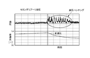
- an upshift is performed in the process of slowly and slightly downshifting and controlling the hydraulic pressure in the hydraulic chamber of the secondary pulley to be substantially constant in order to maintain the pinching pressure substantially constant.
- the situation in which the hydraulic pressure in the hydraulic chamber of the secondary pulley changes greatly when this is done is shown in the diagram.
- the hydraulic pressure in the hydraulic chamber is increased to increase the groove width of the primary pulley, and the groove width of the secondary pulley is forcibly increased accordingly.
- hydraulic pressure may be supplied to the hydraulic chamber of the secondary pulley via the supply valve by clamping pressure control. Therefore, as shown in FIG. 21, immediately after the start of the upshift, the hydraulic pressure in the hydraulic chamber of the secondary pulley pulsates greatly, causing hunting.
- the present invention has been made paying attention to the above technical problem, and is a control of a hydraulic control device configured to control an oil pressure in a hydraulic chamber of a pulley around which a belt is wound by an open / close valve.
- the purpose is to improve the stability.
- each of the pair of pulleys around which the belt is wound increases the thrust in the direction of narrowing the width of the groove around which the belt is wound as the hydraulic pressure increases.
- a hydraulic chamber, the hydraulic pressure of the other hydraulic chamber increases as hydraulic pressure is supplied to one of the hydraulic chambers, and the hydraulic pressure is discharged from either hydraulic chamber.
- the other hydraulic chamber is configured so that the hydraulic pressure is lowered, and a supply valve that is opened when the hydraulic pressure is supplied and a discharge valve that is opened when the hydraulic pressure is discharged communicate with each of the hydraulic chambers.
- a belt-type non-feedback valve is provided, and is configured to perform feedback control of these supply valve and discharge valve based on a deviation between the target hydraulic pressure of the hydraulic chamber and the actual hydraulic pressure so that the hydraulic pressure of each hydraulic chamber becomes a target pressure.
- the control amount of the supply valve communicated with the other hydraulic chamber is The hydraulic pressure of the other hydraulic chamber is smaller than the control amount obtained based on the deviation in a case other than the case where the hydraulic pressure increases with the supply of hydraulic pressure to the one hydraulic chamber, and either one of the hydraulic chambers
- the control amount of the discharge valve communicated with the other hydraulic chamber is set to the hydraulic pressure in the other hydraulic chamber.
- the control amount is set to be smaller than the control amount obtained based on the deviation in a case other than the case where the hydraulic pressure is reduced as the hydraulic pressure is discharged from the hydraulic
- control for reducing the control amount can include control for reducing a predetermined control gain.
- control gain is a control gain that is set larger than the value when the pressure oil temperature is low, or the value when the supply pressure supplied to the supply valve or the discharge valve is high.
- the control gain may be set to be smaller than the value when the value is low.
- control for reducing the control amount can include control for reducing the control amount obtained based on the deviation to zero.
- the one hydraulic chamber is a hydraulic chamber provided in one pulley to which hydraulic pressure is supplied and discharged in order to change a gear ratio, and the other hydraulic chamber sets a belt clamping pressure.
- the hydraulic chamber may be provided in the other pulley to which the hydraulic pressure is supplied and discharged, and the present invention is configured so that when the amount of change in the speed ratio within a predetermined time is within a predetermined reference range, The supply valve and the discharge valve communicated with the other hydraulic chamber may be prohibited from being controlled to reduce the control amount.
- the change in the control amount is changed with a predetermined gradient. You may be comprised so that it may make.
- At least one of the supply valve and the discharge valve includes a cylinder portion that accommodates a piston so as to be movable back and forth, and a first oil that is partitioned by the piston and formed inside the cylinder portion.
- the second oil chamber can be constituted by a balance piston type valve provided with a control solenoid valve for selectively communicating with the low pressure portion.
- control solenoid valve is configured such that the opening degree changes according to the control amount, and the control solenoid valve is opened.
- the throttle portion formed by the control orifice is configured such that the amount of increase in flow resistance accompanying the increase in the viscosity of the pressure oil is greater than the amount of increase in flow resistance at the control orifice, and control of the control solenoid valve
- a control amount setting for setting the amount to a control amount in which the opening degree when the pressure oil temperature is a predetermined temperature is larger than the opening degree when the pressure oil temperature is higher than the predetermined temperature Means may be provided.
- control solenoid valve includes a valve whose opening degree increases as the control amount increases, and the control amount setting means determines the control amount of the control solenoid valve, and the pressure oil temperature is a predetermined temperature.
- means may be included for increasing the temperature of the pressure oil as compared to when the temperature is higher than the predetermined temperature.
- control solenoid valve includes a valve whose opening degree decreases as the control amount increases, and the control amount setting means indicates the control amount of the control solenoid valve when the temperature of the pressure oil is a predetermined temperature.
- a means for reducing the pressure oil as compared with the case where the temperature of the pressure oil is higher than the predetermined temperature may be included.
- the balance piston type valve can incorporate a configuration for reducing the influence caused by the fluctuation of the viscosity of the pressure oil.
- a valve body that is moved in the axial direction by electromagnetic force is pressed against an opening end portion of a port communicating with the second oil chamber, and the valve body is closed. It is configured to open when a gap through which the pressure oil flows away from the opening end portion is generated, and a relationship between the flow rate of the pressure oil and the temperature in the communication passage is partly connected to the control solenoid valve.
- a characteristic adjusting unit may be provided that opens the valve and approximates the relationship between the flow rate of the pressure oil flowing between the valve body and the opening end of the port and the temperature of the pressure oil.
- the characteristic adjusting portion may be an oil hole having an opening area smaller than the flow path cross-sectional area of the communication path and a length longer than the opening diameter.
- the hydraulic control device of the present invention can be configured to suppress the influence caused by fluctuations in supply pressure.
- the control solenoid valve is configured such that the opening degree changes according to a control amount, and the control amount when the supply pressure supplied to the first oil chamber is higher than a predetermined reference pressure.
- Other control amount setting means for setting the control amount so that the opening is smaller than the opening when the supply pressure is low can be provided.
- control solenoid valve is configured to be feedback-controlled based on a deviation between the target pressure and the actual pressure of the hydraulic chamber
- other control amount setting means is a feedback control gain of the control solenoid valve.
- guard setting means for setting a limit value of the stroke amount in the valve opening direction of the valve body based on the deviation between the target value and the actual value of the hydraulic pressure of the hydraulic chamber
- Limiting means for limiting the control amount of the control solenoid valve may be provided so that the stroke amount of the valve body is equal to or less than the limit value.
- valve body is configured to stroke in the valve opening direction by passing a current through the control solenoid valve. Further, a stroke amount calculating means obtained from the above may be provided.
- a stroke amount calculating means for obtaining the stroke amount of the valve body based on the change amount of the hydraulic pressure in the hydraulic chamber.
- the hydraulic control device of the present invention by supplying a predetermined hydraulic pressure to the hydraulic chamber of one pulley and setting the width of the groove around which the belt is wound to a predetermined width, a gear ratio corresponding to the groove width is set.
- the hydraulic pressure is supplied to the hydraulic chamber of the other pulley to set the clamping pressure for clamping the belt, so that the belt and each pulley come into contact with each other with a contact pressure corresponding to the clamping pressure and the predetermined pressure is reached.
- the hydraulic pressure of these hydraulic chambers is controlled by controlling the opening and closing of the supply valve and the discharge valve that are communicated with each other. This is performed by feedback control based on the deviation from the value.
- the control amount of the supply valve that supplies the hydraulic pressure to the other hydraulic chamber is the control amount in the other case. Made smaller.
- the control for reducing the control amount is performed by setting the control amount obtained based on the deviation to zero, or by making the control gain smaller than a preset value. Therefore, the overlap between the increase of the hydraulic pressure of the other hydraulic chamber due to the increase of the hydraulic pressure of the other hydraulic chamber and the increase of the hydraulic pressure supplied via the supply valve is reduced or eliminated, and as a result, Hydraulic overshoot and hunting can be suppressed or eliminated, and hydraulic control can be stabilized.
- the control amount of the discharge valve that discharges the hydraulic pressure from the other hydraulic chamber is the same as in the other cases. It is made smaller than the control amount.
- the control for reducing the control amount is performed by setting the control amount obtained based on the deviation to zero, or by making the control gain smaller than a preset value. Therefore, the overlap between the decrease in the hydraulic pressure of the other hydraulic chamber due to the decrease in the hydraulic pressure of the other hydraulic chamber and the decrease in the hydraulic pressure discharged through the discharge valve is reduced or eliminated. The overshoot and hunting of the hydraulic control can be suppressed or eliminated, and the hydraulic control can be stabilized.
- control gain is changed as described above according to the oil temperature or the supply pressure, it is possible to eliminate or suppress a decrease in control accuracy or instability due to the influence of the viscosity of the pressure oil or the supply pressure.
- the above-described control for reducing the control amount is prohibited.
- the amount of change in the gear ratio within a predetermined time in other words, the change in the hydraulic pressure in one hydraulic chamber has little effect on the hydraulic pressure in the other hydraulic chamber when the transmission speed is low. Therefore, it is required to supply and discharge hydraulic pressure. In a state where the speed change speed is low, the above-described control amount cannot be particularly reduced, so that stable hydraulic control can be performed.
- the control for reducing the control amount of the supply valve or the discharge valve is performed in the specific control state described above, and therefore, the control amount is reduced by the establishment or non-establishment of such a control state.
- a change in the control amount is executed with a predetermined gradient. Therefore, the control stability can be improved by avoiding or suppressing a situation such as the occurrence of control hunting when the control amount is switched.
- the control solenoid valve control amount is changed to increase the opening when compared with the case where the viscosity is small. Therefore, even when the viscosity of the pressure oil increases, the amount of the pressure oil flowing through the throttle portion in the control solenoid valve can be secured to the same extent as when the viscosity is low.
- the control solenoid valve when the control solenoid valve is controlled to open, there is no significant difference between the amount of pressure oil flowing through the throttle and the control orifice when the viscosity of the pressure oil is small and large, and control of the control solenoid valve
- the relationship between the amount and the opening or flow rate of the balance piston valve does not vary with the viscosity of the pressure oil. Therefore, according to the hydraulic control device of the present invention, the controllability of the transmission can be prevented or suppressed from being deteriorated, for example, the controllability of the transmission is changed by the viscosity or the oil temperature of the pressure oil, or the controllability of the transmission is improved. Can be improved.
- the balance piston type valve is opened when the piston moves due to a pressure difference between the first oil chamber and the second oil chamber.
- the pressure difference is the difference in the flow rate of pressure oil between the gap between the valve body and the port that is generated when the control solenoid valve is opened (that is, the throttle part) and the characteristic adjustment part provided in the communication path.
- the flow resistance in the throttle portion generated when the control solenoid valve is opened increases when the temperature of the pressure oil decreases and its viscosity increases, and the relationship between the flow rate and temperature and the flow rate and temperature in the communication path. Is approximated or equalized by providing the characteristic adjusting portion in the communication path.
- the relationship between the amount of hydraulic pressure flowing out from the second oil chamber when the control solenoid valve is opened and the amount of pressure oil flowing into the second oil chamber through the communication path is the pressure associated with the change in oil temperature. Any change in the viscosity of the oil will be the same or approximate. That is, according to the hydraulic control device according to the present invention, the influence of the decrease in oil temperature and the accompanying increase in viscosity does not occur or is suppressed, so that deterioration of controllability can be prevented or suppressed, or the transmission The controllability can be improved.
- the control amount of the control solenoid valve when the supply pressure is high is greater than the opening when the supply pressure is low. This is a control amount for setting the small opening. Therefore, the pressure difference between the first oil chamber and the second oil chamber when the control solenoid valve is opened is controlled so that the control amount of the control solenoid valve is set as described above even if the supply pressure is high. It is not particularly large because the amount of hydraulic pressure discharged from the chamber is suppressed. That is, the influence of the high supply pressure is not exerted on the supply of hydraulic pressure to the hydraulic chamber or the discharge of the hydraulic pressure, or the influence is suppressed, so that stable hydraulic control can be performed.
- the hydraulic control device of the present invention when the control solenoid valve in the balance piston valve is energized and controlled to open, and the second oil chamber communicates with the low pressure portion, the second oil chamber is discharged and the second oil chamber is discharged. Since the supply of hydraulic pressure from the high pressure section to the two oil chambers is limited by the control orifice, a pressure difference is generated in the hydraulic pressure between the first oil chamber and the second oil chamber, and as a result, the piston and the valve body integrated therewith are provided. When the force pressing toward the second oil chamber, that is, the force in the valve opening direction becomes larger than the force in the valve closing direction, the valve body moves backward together with the piston toward the second oil chamber and opens.
- the control amount of the control solenoid valve is limited so that the stroke amount of the valve body that moves backward is equal to or less than the guard value, and the valve body does not move backward beyond the guard value. Since the guard value is set based on the deviation between the target hydraulic pressure of the hydraulic chamber, which is the hydraulic control target location, and the actual hydraulic pressure, the degree of opening caused by the backward movement of the valve body is excessive with respect to the deviation. As a result, it is possible to prevent or suppress the actual hydraulic pressure in the hydraulic chamber from exceeding the target hydraulic pressure and becoming excessively high or conversely low.
- the valve body strokes due to the pressure difference between the oil chambers on both sides sandwiching the piston, and the stroke amount of the valve body is controlled even though the position is not particularly controlled depending on the hydraulic pressure. Since the guard value of the stroke amount is obtained, even if the hydraulic pressure is controlled at a flow rate that causes the valve body to move backward to the middle of the entire stroke range, that is, even if the flow rate is small. The oil pressure can be controlled stably as expected.
- the control can be performed without requiring a measuring device such as a stroke sensor.
- the estimation accuracy can be improved.
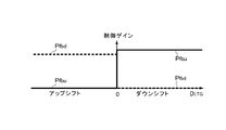
- FIG. 1 It is explanatory drawing which shows typically the value for every upshift and downshift of the control gain about the supply valve and discharge valve in the control example shown in FIG. 1 is a diagram schematically showing a belt-type continuously variable transmission, a hydraulic control circuit thereof, and a control system that are objects of the present invention.
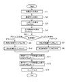
- FIG. It is a schematic diagram which shows in principle the structure of the balance piston type valve which comprises the supply valve or the discharge valve. It is explanatory drawing explaining the relationship between the control orifice, the 2nd oil chamber, and control pressure. It is a flowchart for demonstrating an example of the control comprised by the hydraulic control apparatus which concerns on this invention, and was comprised so that the influence of the change of the temperature or the viscosity of pressure oil might be reduced.
- the belt type continuously variable transmission targeted by the present invention is such that a pair of pulleys around which a belt is wound changes the width of a groove around which the belt is wound, thereby winding the belt around each pulley.
- the transmission is configured such that the radius is continuously changed, and thereby the gear ratio is continuously changed. Therefore, torque is transmitted by the frictional force between the belt and the pulley.
- control for setting and changing the gear ratio and control for pinching the belt by the pulley in order to set the transmission torque capacity to a predetermined capacity are performed by hydraulic pressure. Yes.
- each pulley is provided with a hydraulic chamber, and the hydraulic control device according to the present invention is configured to supply or discharge hydraulic pressure to these hydraulic chambers.
- FIG. 8 schematically shows a belt-type continuously variable transmission and a hydraulic circuit for setting the gear ratio and belt clamping pressure.
- the belt type continuously variable transmission 1 includes a driving pulley (primary pulley) 2 to which torque of a driving force source (not shown) such as an engine is transmitted, and an output member (not shown) such as an output shaft and an output gear.
- a belt 4 is wound around a driven pulley (secondary pulley) 3 that outputs torque, and the torque is transmitted between the pulleys 2 and 3 via the belt 4.
- Each pulley 2 and 3 is configured so that the width of the belt groove around which the belt 4 is wound can be changed.
- the primary pulley 2 is composed of a fixed sheave 2A and a movable sheave 2B arranged so as to be able to approach and separate from the fixed sheave 2A, and is provided on the back side of the movable sheave 2B.
- the movable sheave 2B is moved to the fixed sheave 2A side or separated from the fixed sheave 2A by the hydraulic pressure supplied to or discharged from the hydraulic chamber 2C.
- the secondary pulley 3 is constituted by a fixed sheave 3A and a movable sheave 3B arranged so as to be able to approach and separate from the fixed sheave 3A, and is provided on the back side of the movable sheave 3B.
- the movable sheave 3B is moved to the fixed sheave 3A side or separated from the fixed sheave 3A by the hydraulic pressure supplied to or discharged from the hydraulic chamber 3C.
- the belt 4 is sandwiched between the sheaves 3A and 3B by the hydraulic pressure supplied to the hydraulic chamber 3C of one of the pulleys (for example, the secondary pulley 3), and the belt 4 and the sheaves 3A and 3B are sandwiched by the clamping pressure.
- a transmission torque capacity corresponding to the frictional force is set.
- each pulley of the belt 4 is changed by changing the interval (groove width) between the sheaves 2A and 2B by supplying or discharging the hydraulic pressure to the hydraulic chamber 2C of the other pulley (for example, primary pulley 2).
- the wrapping radius with respect to 2 and 3 is changed to cause a shift.
- the hydraulic pressure in the hydraulic chambers 2C and 3C in each of the pulleys 2 and 3 is configured to be controlled by appropriately supplying and discharging the hydraulic pressure.
- the original pressure is the hydraulic pressure of a hydraulic source 5 such as an oil pump or an accumulator.
- a hydraulic source 5 such as an oil pump or an accumulator.
- the oil pump is a so-called mechanical oil pump or motor driven by the driving force source. It may be an electric oil pump that is driven.
- a supply oil passage (or line pressure oil passage) 7 communicated with the hydraulic power source 5 through the check valve 6 is communicated with each of the hydraulic chambers 2C and 3C and communicated with the hydraulic chamber 2C of the primary pulley 2.
- a supply valve 8 is provided in the supply oil passage 7, and the supply valve 8 is controlled to be opened and closed, whereby the hydraulic pressure is supplied to the hydraulic chamber 2 ⁇ / b> C and the supply of the hydraulic pressure is shut off.
- a supply valve 9 is provided in the supply oil passage 7 communicated with the hydraulic chamber 3C of the secondary pulley 3, and the supply valve 9 is controlled to open and close to supply hydraulic pressure to the hydraulic chamber 3C. Is configured to shut off the supply.
- a discharge valve 10 communicates with the hydraulic chamber 2C of the primary pulley 2. By controlling the opening and closing of the discharge valve 10, the hydraulic pressure is discharged from the hydraulic chamber 2C to a predetermined drain location, and the discharge of the hydraulic pressure is shut off. Is configured to do.
- a discharge valve 11 is communicated with the hydraulic chamber 3C of the secondary pulley 3. By controlling the discharge valve 11, the hydraulic pressure is discharged from the hydraulic chamber 3C to a predetermined drain location. It is configured to shut off the discharge of hydraulic pressure.
- These supply valves 8 and 9 and discharge valves 10 and 11 are electrically controlled solenoid valves, which are controlled to open and supply and discharge hydraulic pressure, and can control the flow rate according to the opening degree.
- the valve itself has no pressure regulation function. Therefore, the supply valves 8 and 9 and the discharge valves 10 and 11 are feedback-controlled based on the pressure deviation between the target pressure and the actual oil pressure, so that the oil pressure in the hydraulic chambers 2C and 3C is controlled to the target oil pressure. It is configured.
- Various sensors for obtaining data for the control are provided. For example, a line pressure sensor 12 that detects a line pressure Pl that is a source pressure and outputs a signal, and a hydraulic chamber 2C of the primary pulley 2 is provided.
- a primary hydraulic sensor 13 for detecting the hydraulic pressure Ppri and outputting a signal, and a secondary hydraulic sensor 14 for detecting the hydraulic pressure Psec of the hydraulic chamber 3C of the secondary pulley 3 and outputting a signal are provided. Further, a primary rotational speed sensor 15 that detects the rotational speed Npri of the primary pulley 2 and outputs a signal and a secondary rotational speed sensor 16 that detects the rotational speed Nsec of the secondary pulley 3 and outputs a signal are provided. .
- An electronic control unit (ECU) 17 for controlling the supply valves 8 and 9 and the discharge valves 10 and 11 is provided.
- the electronic control unit 17 is mainly composed of a microcomputer, performs calculation using various input data and data stored in advance, and outputs the result of the calculation as a control command signal. It is configured. Therefore, the electronic control unit 17 includes data detected by the sensors 12 to 16, that is, the line pressure Pl, the hydraulic pressure Ppri of the hydraulic chamber 2C of the primary pulley 2, the hydraulic pressure Psec of the hydraulic chamber 3C of the secondary pulley 3, The rotational speeds Npri and Nsec of the pulleys 2 and 3 are input.
- the supply valve and the discharge valve may be valves that are controlled to open and close and that can control the opening degree as described above, and may be configured by a balance piston type valve as an example. it can.
- each of the supply valves 8 and 9 and the discharge valves 10 and 11 is constituted by a balance piston type valve.
- each balance piston type valve has the same configuration, and the configuration will be described with reference to FIG.
- the hydraulic source 5 or the line pressure PlP for the supply valves 8 and 9 is the high pressure section
- the hydraulic chambers 2C and 3C are the low pressure sections
- the hydraulic chamber 2C and the discharge valves 10 and 11 are the hydraulic chamber 2C
- 3C is described as a high pressure part
- a drain location is described as a low pressure part.
- a piston 22 integrated with the valve body 21 is accommodated in a cylinder portion 23 so as to be movable back and forth. Therefore, the inside of the cylinder portion 23 is partitioned into two oil chambers 24 and 25 by the piston 22, and the oil chamber 24 in which the valve body 21 is accommodated is included in the oil chamber 24 and 25.
- An inflow port 27 to which hydraulic pressure is supplied and an outflow port 29 through which the hydraulic pressure flows out toward the low pressure portion 28 are formed.
- the outflow port 29 is formed in the end plate portion on the distal end side of the valve body 21 so that the outflow port 29 is closed when the valve body 21 abuts and the outflow port 29 is opened when the valve body 21 is retracted. It is configured.
- a spring 30 that presses the piston 22 toward the outflow port 29 is disposed in the oil chamber 25 on the opposite side of the piston 22 with respect to the oil chamber 24 in which the valve body 21 is accommodated.
- a port 31 is formed.
- the signal pressure port 31 and the inflow port 27 are communicated with each other by a communication passage 33 having a control orifice 32.
- the control orifice 32 is for restricting the flow rate by restricting the pressure oil flowing from the high pressure portion 26 or the oil chamber 24 toward the oil chamber 25, and for example, a thin plate material having a minute through hole, It is formed so as to cross the communication path 33.
- the communication passage 33 is mainly for communicating the oil chambers 24 and 25, and therefore may be formed so as to penetrate the piston 22 in the axial direction or the inner surface of the cylinder portion 23. It may be formed.
- a control solenoid valve 34 for selectively communicating the oil chamber 25 in which the spring 30 is disposed with the low pressure portion 28 is provided. More specifically, an outflow port 35 is formed in the oil chamber 25, and a control solenoid valve 34 is connected to the outflow port 35.
- the control solenoid valve 34 includes an electromagnetic coil 38 that presses a shaft-shaped valve body 36 in the axial direction by a spring 37 and generates an electromagnetic force that pulls the valve body 36 in the axial direction against the spring 37. Yes.
- an inflow port 39 communicating with the outflow port 35 is formed on the distal end side of the valve body 36, and an open end of the inflow port 39 is a valve seat, and the distal end of the valve body 36 is at the open end.
- the inflow port 39 is hermetically sealed when the parts abut against each other, and the inflow port 39 is opened when the valve body 36 is separated, and the degree of opening according to the amount of current supplied to the electromagnetic coil 38 is set. ing. Furthermore, the outflow port 40 which connects the location in which the valve body 36 is accommodated to the low voltage
- the axial force acting on the piston 22 and the valve body 21 integrated therewith is as follows.
- the force acting in the right direction in FIG. 9 is generated by the oil pressure Ps of the oil chamber 25 (hereinafter also referred to as the second oil chamber) in which the signal pressure port 31 is formed, and the pressure receiving area in the piston 22. Is As, the axial force directed to the right is “Ps ⁇ As”.
- the forces acting in the left direction in FIG. 9 are the oil pressure Pl of the high pressure portion 26 and the oil pressure Pr of the low pressure portion 28, assuming that the respective pressure receiving areas are Am and Ar, the axial force toward the left direction is “P1 ⁇ Am + Pr ⁇ Ar”.
- the pressure receiving area Am on which the hydraulic pressure Pl of the high pressure portion 26 acts is an area obtained by subtracting the cross sectional area of the valve body 21 from the cross sectional area of the piston 22, and the pressure receiving area Ar on which the hydraulic pressure Pr of the low pressure portion 28 acts is almost equal. It is a cross-sectional area of the outflow port 29. If the right direction in FIG. 9 is a negative direction and the elastic force of the spring 30 is ignored, the axial force acting on the piston 22 and the valve body 21 integrated therewith is ⁇ Ps ⁇ As + Pl ⁇ Am + Pr ⁇ Ar It becomes.
- the hydraulic pressure Ps in the second oil chamber 25 when operating in this way passes through the control orifice 32 and the amount Qc of pressure oil supplied from the high pressure portion 26 to the second oil chamber 25 and the control solenoid valve 34. This is proportional to the difference (Qc ⁇ Qs) from the amount Qs of the pressure oil discharged to the low pressure portion 28.
- This relationship is schematically shown in FIG.
- the flow rate Qc of the pressure oil flowing from the high pressure portion 26 to the second oil chamber 25 is restricted by the control orifice 32.
- the flow rate Qs ⁇ of the pressure oil flowing from the second oil chamber 25 to the low pressure portion 28 is small when the control solenoid valve 34 does not need to flow a large amount of pressure oil. Since the area is small, the flow rate is restricted due to the throttling action of the portion (throttle portion).
- the target gear ratio is obtained based on the traveling state such as the accelerator opening degree and the vehicle speed of the vehicle on which the belt type continuously variable transmission is mounted, and the actually set speed is determined by the primary pulley 2 and the secondary pulley. It can obtain
- FIG. Based on the deviation between the target gear ratio and the actual gear ratio, the target oil pressure of the hydraulic chamber 2C in the primary pulley 2 is obtained, and based on the pressure deviation between the target oil pressure and the actual oil pressure detected by the primary oil pressure sensor 13.
- the supply valve 8 or the discharge valve 10 is controlled to supply the hydraulic pressure to the hydraulic chamber 2C, or the hydraulic pressure is discharged from the hydraulic chamber 2C.
- the control amount (specifically, current) in that case is obtained from the pressure deviation and the feedback control gain.
- the control gain is appropriately set by design so that no control response delay occurs and control hunting does not occur, as in the widely known normal feedback control. Further, since the hydraulic pressure of the hydraulic chamber 3C in the secondary pulley 3 is for setting the belt clamping pressure, it is obtained based on the required driving amount in the vehicle such as the accelerator opening.
- the supply valve 9 or the discharge valve 11 is controlled to supply the hydraulic pressure to the hydraulic chamber 3C, or from the hydraulic chamber 3C. Hydraulic pressure is discharged.
- the control amount (specifically, current) in that case is obtained from the pressure deviation and the feedback control gain.
- the control gain is appropriately set by design so that no control response delay occurs and control hunting does not occur, as in the widely known normal feedback control.
- the hydraulic pressures of the hydraulic chambers 2C and 3C when performing such gear ratio control and clamping pressure control are not only changed by controlling the supply valves 8 and 9 or the discharge valves 10 and 11 to open,
- the tension of the belt 4 changes as the hydraulic pressure in the chamber 2C (or 3C) changes, and this also changes as the reaction force that pushes the groove width in the pulleys 2 and 3 changes.
- the hydraulic control device according to the present invention is configured to perform the control described below. Yes.
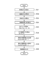
- FIG. 1 is a flowchart for explaining an example of the control.
- the control example shown here when the shift control is started in a state in which the hydraulic pressure of the hydraulic chamber 3C of the secondary pulley 3 is feedback controlled, In this example, the control amount of the supply valve 9 and the discharge valve 11 for the secondary pulley 3 is made different from the control amount in the normal case where the shift control does not occur according to the contents of the shift.
- the routine shown in FIG. 1 is repeatedly executed every predetermined short time. First, the target pressure PoP and the control pressure Pr are calculated (steps S1 and S2). The calculation of these data may be performed in the order shown in FIG. 1, may be performed in a different order, or may be performed in parallel.
- the target pressure P0 can be obtained based on the required amount of driving such as the accelerator opening or the rate of change thereof.
- the control pressure Pr is the hydraulic pressure in the hydraulic chamber 3C of the secondary pulley 3, and may be a value detected by the secondary hydraulic sensor 14 described above.
- the control gain Pfb is obtained (step S3).
- the control gain Pfb is a coefficient of a proportional term, a differential term or an integral term in the feedback control, and is set in advance so that a control response delay does not occur in particular and control hunting does not occur.
- the value GAIN may be a constant value, or may be a value that takes into account other factors that affect the flow of pressure oil passing through the supply valves 8 and 9 and the discharge valves 10 and 11.
- the throttle formed in the opening may be a throttle having a flow path length longer than that of the control orifice 32.
- the flow resistance at the throttle portion and the flow resistance at the control orifice 32 may differ greatly depending on the oil temperature.
- the control gain Pfb may be set to a larger value as the oil temperature is lower.
- the hydraulic pressure (that is, the supply pressure) in the portion corresponding to the high pressure portion 26 described above is high, the force that presses the piston 22 and the valve body 21 in the valve opening direction is greater than when the hydraulic pressure is low. That is, it becomes easy to open the valve.
- the control gain Pfb may be set to a smaller value as the supply pressure is higher.
- a gear ratio change amount DLTG is obtained (step S5).
- the gear ratio change amount DLTG is a change amount obtained by subtracting the gear ratio value obtained when the routine of FIG. 1 was previously executed from the gear ratio value obtained this time. Calculated as a “negative” value. Since this is the speed ratio change amount in one cycle time of the routine of FIG. 1, it is equivalent to the speed change speed.
- the gear ratio change amount DLTGD may be obtained before the control gain Pfb and the pressure deviation DP, or may be obtained simultaneously with these.
- step S6 It is determined whether or not the gear ratio change amount DLTG obtained in step S5 is greater than or equal to “0” (step S6). If the gear ratio change amount DLTG is “0” or more, the gear ratio has increased, so a downshift has occurred. On the other hand, if the gear ratio change amount DLTG is less than “0”, the gear ratio is Since it is smaller, an upshift has occurred. Therefore, if a negative determination is made in step S6 due to the occurrence of an upshift, the feedback control gain Pfbu for the supply valve 9 communicated with the hydraulic chamber 3C of the secondary pulley 3 is not shifted. A value smaller than the control gain in the normal state is set (step S7). For example, the control gain Pfbu is set to “0”.
- the control in step S7 is a control for reducing the control amount for the supply valve 9. Therefore, instead of reducing the control gain Pfbu, a predetermined correction is made to the control amount obtained by the normal control gain Pfb.
- the control amount may be corrected to decrease by multiplying by a coefficient, or the control amount for the supply valve 9 may be corrected to decrease by multiplying the pressure deviation by a predetermined correction coefficient and correcting the decrease. . In this case, the control amount need only be smaller than the normal amount and does not have to be “0”.
- the feedback control gain Pfbd for the discharge valve 11 is set to the normal control gain Pfb that is predetermined in design (step S8).
- normal feedback control is executed for the discharge valve 11.
- the control gain Pfb may be a value corrected based on the oil temperature or the supply pressure.
- the feedback control gain Pfbu for the supply valve 9 communicated with the hydraulic chamber 3C of the secondary pulley 3 is designed by design.
- the predetermined normal control gain Pfb is set (step S9).
- the normal feedback control is executed for the supply valve 9.
- the control gain Pfb may be a value corrected based on the oil temperature or the supply pressure.
- the feedback control gain Pfbd for the supply valve 9 communicated with the hydraulic chamber 3C of the secondary pulley 3 is set to a value smaller than the control gain in the normal state where no shift is occurring (step S10). For example, the control gain Pfbd is set to “0”.
- the control in step S10 is a control for reducing the control amount for the discharge valve 11. Therefore, instead of reducing the control gain Pfbd, a predetermined correction is made to the control amount obtained by the normal control gain Pfb.
- the control amount may be corrected to decrease by multiplying the coefficient, or the control amount for the discharge valve 11 may be corrected to decrease by multiplying the pressure deviation by a predetermined correction coefficient and correcting the decrease. . In this case, the control amount need only be smaller than the normal amount and does not have to be “0”.
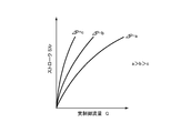
- FIG. 2 shows the difference between the values of the feedback control gain Pdbu for the supply valve 9 and the feedback control gain Pfbd ⁇ ⁇ ⁇ for the discharge valve 11 set in this way in the upshift and the downshift.
- the solid line indicates the feedback control gain Pfbu for the supply valve 9
- the broken line indicates the feedback control gain Pfbd for the discharge valve 11.
- control amount Isolu of the supply valve 9 is calculated (Step S11), or the control amount Isold of the discharge valve 11 is calculated (Step S12).
- control amounts Isolu and Isold are, for example, current values, and the relationship between the current value and the opening (or opening diameter) is determined by the configuration of the supply valve 9 or the discharge valve 11, and therefore the relationship is an arithmetic expression or a map. Can be prepared in advance. Therefore, the control in step S11 and step S12 can be calculated from the map using, for example, the control gain Pfb and the pressure deviation DP as arguments.
- the parameters for calculating the control amount require the control gain Pfb and the pressure deviation DP described above.
- the supply pressure Pl ⁇ ⁇ is added to this parameter, or a speed change mode such as the manual mode or the automatic mode is added.
- a driving mode such as a mode or a normal mode may be added. That is, correction such as giving priority to control responsiveness or giving priority to control stability may be added.
- Step S13 the control amounts Isolu, Isold calculated in Step S11 or Step S12 are output as control command signals (Step S13), and the supply valve 9 or the discharge valve 11 is controlled to an opening degree corresponding to the control amounts Isolu, Isold. Is done.
- the control solenoid valve 34 in the balance piston type valve constituting the supply valve 9 and the discharge valve 11 shown in FIG. 9 is energized, and the control solenoid valve 34 is opened according to the current.
- the control amount of the supply valve 9 is reduced and set to, for example, “0”. That is, even if a pressure deviation that causes the actual hydraulic pressure to be lower than the target hydraulic pressure occurs, the hydraulic pressure is not supplied in accordance with the pressure deviation, for example, no hydraulic pressure is supplied.
- the width of the belt winding groove in the primary pulley 2 is reduced and the winding radius of the belt 4 is increased, and accordingly, the groove width in the secondary pulley 3 is reduced.
- the belt 4 is pushed and spread, so that the volume of the hydraulic chamber 3C of the secondary pulley 3 is reduced and the pressure is increased.
- the discharge valve 11 is controlled in the same manner as normal, and the hydraulic pressure is discharged from the hydraulic chamber 3C without excess or deficiency. That is, the hydraulic pressure in the hydraulic chamber 3C does not decrease excessively. Therefore, when the hydraulic pressure is not excessively supplied to the hydraulic chamber 3C in the secondary pulley 3 and the hydraulic pressure does not increase excessively, and when the hydraulic pressure in the hydraulic chamber 3C is higher than the target pressure, Since the hydraulic pressure is discharged without excess or deficiency, occurrence of control hunting is avoided or suppressed. That is, stable hydraulic control is performed.
- the supply valve 9 is controlled in the same manner as normal, and the hydraulic pressure is supplied to the hydraulic chamber 3C without excess or deficiency. That is, the hydraulic pressure in the hydraulic chamber 3C does not increase excessively. Therefore, when the hydraulic pressure is not excessively discharged from the hydraulic chamber 3C in the secondary pulley 3 and accordingly the hydraulic pressure is not excessively reduced, and when the hydraulic pressure in the hydraulic chamber 3C is lower than the target pressure, Since the hydraulic pressure is supplied without excess or deficiency, occurrence of control hunting is avoided or suppressed. That is, stable hydraulic control is possible.
- step S6 in the control example shown in FIG. 1 is a step for determining the content of the shift as described above, and therefore the determination is made based on other data regardless of the gear ratio change amount DLTGLT. It is good as well.
- step S6 in FIG. 1 described above is changed to a determination step (step S6-1) for determining the contents of the shift command, and step S5 is deleted at the same time. The contents are the same as those in the control example shown in FIG.
- the control example shown in FIG. 4 is performed when the step shown in the flowchart shown in FIG. 1 described above determines whether or not the gear ratio change amount DLTG is within a predetermined range and the determination result is affirmative. This is an example in which a step of prohibiting control for reducing the gain is added. Therefore, in the following description, the same reference numerals as those in FIG. 1 are assigned to the steps that perform the same control as the control steps in the flowchart shown in FIG. Different control steps will be described.
- step S5 After the gear ratio change amount DLTGLT is calculated in step S5, it is determined whether or not the gear ratio change amount DLTG is within a predetermined range (step S51). Specifically, it is determined whether or not the gear ratio change amount DLTG is not less than “ ⁇ ” and not more than “+ ⁇ ”. These upper and lower limit values “ ⁇ ” and “+ ⁇ ” that determine the reference range indicate that the hydraulic pressure in the hydraulic chamber 3C is excessive even if the shift control and the control of the hydraulic pressure in the hydraulic chamber 3C in the secondary pulley 3 overlap.
- the range within which the hydraulic pressure in the hydraulic chamber 3C can be controlled as expected without being changed is determined in advance by experiments or the like. This is because the amount of leakage of hydraulic oil and the hydraulic rigidity associated with the hydraulic chambers 2C and 3C and the circuit or device structure for controlling the hydraulic pressure affect the stability of hydraulic control.
- step S51 the control gain Pfbu for the supply valve 9 that controls the hydraulic pressure of the secondary pulley 3 and the discharge valve 11 are determined.
- Each of the control gains Pfbd is set to a value Pfb that is predetermined in design as a normal control gain (steps S52 and S53). In other words, even if the gear ratio changes and a gear shift occurs, the control to decrease any control gain is prohibited due to a small gear ratio change amount per unit time, and the value is maintained in the normal state. Is done. If the control amount itself is corrected or the pressure deviation is corrected instead of the control for changing the control gain, the correction may be prohibited.
- step S6-2 it is determined whether the shift is an upshift or a downshift. In the example shown in FIG. 4, it is determined whether or not the gear ratio change amount DLTG is greater than the upper limit value “+ ⁇ ” that defines the above range. If a negative determination is made in step S6-2, the gear ratio change amount DLTG is smaller than the lower limit value “ ⁇ ” that defines the above range, and the current gear shift is an upshift. Therefore, the process proceeds to step S7 and step S8, and the control amount for the supply valve 9 is decreased from the normal time (more specifically, the control gain Pfbu is set to “0”). The control amount is maintained at the normal control amount (more specifically, the control gain Pfbdf is maintained at the normal value Pfb).
- step S6-2 if the gear ratio change amount DLTG ⁇ exceeds the upper limit value “+ ⁇ ” that defines the above range and a positive determination is made in step S6-2, the current gear shift is downshifted. It will be. Therefore, in this case, the process proceeds to step S9 and step S10, and the control amount for the supply valve 9 is maintained at the normal control amount (more specifically, the control gain Pfbu is maintained at the normal value Pfb). Further, the control amount for the discharge valve 11 is decreased from the normal time (more specifically, the control gain Pfbd is set to “0”).
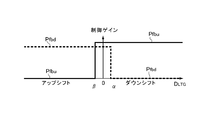
- FIG. 5 shows the difference between the values of the feedback control gain Pdbu for the supply valve 9 and the feedback control gain Pfbd for the discharge valve 11 set in this way in the upshift and the downshift.
- the solid line indicates the feedback control gain Pfbu for the supply valve 9
- the broken line indicates the feedback control gain Pfbd for the discharge valve 11.
- step S11 the control amount Isolu of the supply valve 9 is calculated based on the pressure deviation DP and the control gain Pfbu.
- the control amount Isold of the discharge valve 11 is calculated, and the control amounts Isolu and Isold are output as control command signals.
- the hydraulic pressure in the hydraulic chambers 2C and 3C of the pulleys 2 and 3 in the belt-type continuously variable transmission not only changes due to the supply or discharge of the hydraulic pressure, but also changes the traveling state such as the accelerator opening and the vehicle speed. Along with this, the wrapping radius and the clamping pressure of the belt 4 also change. The influence on the change in the hydraulic pressure due to the change in the running state becomes larger as the shift speed is faster, for example. Therefore, in the control example shown in FIG. 4, when the gear ratio change amount DLTGD is within a predetermined range, the control gain is set to a value in a normal state in which the gear shift control is not superimposed.
- the control example shown in FIG. 6 is an example in which the above-described control gains Pfbuf and Pfbd are configured to change smoothly with a predetermined gradient when changing to a large or small value according to the gear ratio change amount DLTG or the shift speed. That is, in the control example shown in FIG. 6, the control gain Pfbu for the supply valve 9 is set to “0” during the upshift in the control example shown in FIG. In the control example shown in FIG. 1 described above, the control gain Pfbd for the discharge valve 11 is set to “0” at the time of downshift. Pfbd is a function of the gear ratio change amount DLTG, and other control steps are configured in the same manner as the control example shown in FIG. Therefore, in the following description, the same reference numerals as those in FIG. 1 are assigned to the steps for performing the same control as the control steps in the flowchart shown in FIG. Different control steps will be described.
- the control gain Pfbu for the supply valve 9 is It is set to a value represented by a function having at least two of the gear ratio change amount DLTG and the normal value Pfb as variables (step S7-1).
- the function is that the gear ratio change amount DLTGLT or the shift speed is close to “0” when the gear ratio change amount DLTG or the shift speed is between the above-mentioned lower limit values “ ⁇ ” and “0”.
- the function is set so that the control gain Pfbu gradually increases from “0”.
- the control gain Pfbu ⁇ ⁇ may be a function that changes linearly with respect to a change in the gear ratio change amount DLTG or a change in speed, or a function that changes as represented by a quadratic curve.
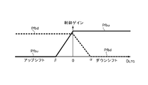
- FIG. 7 shows an example of linear change.
- the solid line indicates the feedback control gain Pfbu for the supply valve 9
- the broken line indicates the feedback control gain Pfbd for the discharge valve 11.
- step S6 a control gain for the discharge valve 11 is determined.
- Pfbd is set to a value represented by a function having at least two of the gear ratio change amount DLTG and the normal value Pfb as variables (step S10-1). The function is that when the transmission ratio change amount DLTG or the transmission speed is between the upper limit values “+ ⁇ ” and “0” in the above-described range, the control gain Pfbd increases as the transmission ratio change amount DLTG or the transmission speed increases. Is a function set so as to gradually approach “0”.
- the control gain Pfbd may be a function that changes linearly with respect to the change in the gear ratio change amount DLTG or the change in the transmission speed, or may be a function that changes as represented by a quadratic curve.
- FIG. 7 shows an example of linear change.
- the control example configured as shown in FIG. 6 even if the absolute value of the upper / lower limit value defining the speed ratio change amount DLTG or the range of the shift speed is relatively large, it is close to the upper limit value or the lower limit value.
- one of the control gains Pfbu and Pfbd is set to a small value, and the control amount is smaller than the control amount in the normal state, so that control stability is secured by preventing or suppressing hydraulic hunting and the like. be able to.
- the control gains Pfbu and Pfbd do not change abruptly as the transmission ratio change amount DLTG ⁇ ⁇ or the transmission speed changes, it is possible to prevent or suppress a sense of incongruity such as a shock.
- control gain or the control amount for the supply valve 9 and the discharge valve 11 that control the hydraulic pressure of the hydraulic chamber 3C of the secondary pulley 3 is changed in relation to the shift.
- control gain or control amount for the supply valve 8 and the discharge valve 10 for controlling the hydraulic pressure of the hydraulic chamber 2C of the primary pulley 2 is related to the control for changing the clamping pressure.
- the control to be changed can be applied in the same manner as described in the specific example described above.
- the pressure oil used for control changes in viscosity according to its temperature.
- the hydraulic control apparatus according to the present invention can be configured to reduce the influence of such a change in oil temperature or a change in the viscosity of pressurized oil and maintain the hydraulic controllability in a good state.
- the control for that is control for changing the control amount of the control solenoid valve 34 in accordance with the oil temperature related to the viscosity of the pressure oil, an example of which is shown in the flowchart of FIG.
- the supply valves 8 and 9 and the discharge valves 10 and 11 configured by the balance piston type valve having the configuration shown in FIG.
- the target pressures of the hydraulic chambers 2C and 3C which are control targets
- Feedback control is performed so that the hydraulic pressure (control pressure) becomes the target pressure.
- the control pressure is lower than the target pressure
- the supply valves 8 and 9 are controlled to open, and the hydraulic pressure of the hydraulic source 5 is supplied to the hydraulic chambers 2C and 3C.
- the discharge valves 10 and 11 are controlled to be opened and discharged from the hydraulic chambers 2C and 3C.
- the control amount in each case is obtained based on the pressure deviation between the target pressure and the control pressure and a predetermined control gain.
- the routine shown in FIG. 11 is repeatedly executed every predetermined short time.
- the target pressure Po, the control pressure Pr, the supply pressure Pl, and the control oil temperature Toil are calculated (step).
- the calculation of these data may be performed in the order shown in FIG. 11, or may be performed in a different order, and may be performed in parallel.
- the target pressure P0 is a hydraulic pressure that sets a target gear ratio for the hydraulic chamber 2C of the primary pulley 2, and the target gear ratio is the optimum for the required driving amount such as the accelerator opening, the vehicle speed, and the driving force source.
- the target hydraulic pressure Po for the hydraulic chamber 2C of the primary pulley 2 can be determined based on the target gear ratio, the ratio of axial thrusts of the primary pulley 2 and the secondary pulley 3, and the like. be able to.
- the hydraulic pressure in the hydraulic chamber 3C of the secondary pulley 3 is a hydraulic pressure that generates a belt clamping pressure and is used for setting a transmission torque capacity. Can be based on.
- the control pressure Pr ⁇ , the supply pressure Pl, and the control oil temperature Toil may be values detected by sensors.
- control gain Pfb is obtained (step S35).
- the control gain Pfb is a coefficient of a proportional term, a differential term or an integral term in the feedback control, and is set in advance so that a control response delay does not occur in particular and control hunting does not occur.
- the control gain Pfb is set to a value corresponding to the oil temperature Toil in addition to the supply pressure Pl and the control pressure Pr. Specifically, when the oil temperature Toil ⁇ is lower than a predetermined temperature, the control gain Pfb is set to a larger value as the oil temperature Toil is lower, and an example thereof is schematically shown in FIG.
- the predetermined temperature is a temperature determined as an increase in the viscosity of the pressure oil starts to affect the controllability of the hydraulic pressure, and can be determined in advance by an experiment or the like.
- the reason why the control gain Pfb is increased on the low oil temperature side is to compensate for an increase in the control amount that the viscosity of the pressure oil increases and its fluidity decreases, and therefore the oil temperature Toil or If the viscosity of the pressure oil does not particularly affect the controllability, the control gain Pfb is maintained at a value set in the prior art, and is set to a larger value as the temperature becomes lower or higher. Finally, the upper limit is set and maintained.
- control gain Pfb is increased in the present invention when the increase in the viscosity of the pressure oil accompanying the decrease in the oil temperature Toil affects the controllability.
- control gain Pfb a control gain Pfbu for the supply valves 8 and 9 and a control gain Pfbd for the discharge valves 10 and 11 are obtained, respectively.
- These control amounts Isolu and Isold are, for example, current values, and the relationship between the current value and the opening (or opening diameter) is determined by the configuration of the control solenoid valve 34. Therefore, the relationship is prepared in advance as an arithmetic expression or a map. Can be kept.
- control in step S37 and step S38 can be calculated from the map using, for example, the control gain Pfb and the pressure deviation DP as arguments.
- the parameters for calculating the control amount require the control gain Pfb and the pressure deviation DP described above.
- the supply pressure Pl ⁇ ⁇ is added to this parameter, or a speed change mode such as the manual mode or the automatic mode is added.
- a driving mode such as a mode or a normal mode may be added. That is, correction such as giving priority to control responsiveness or giving priority to control stability may be added.
- Step S39 the control amounts Isolu, Isold calculated in Step S37 or Step S38 are output as control command signals (Step S39), and the supply valves 8, 9 or the discharge valves 10, 11 correspond to the control amounts Isolu, Isold.
- the opening is controlled. More specifically, the control solenoid valve 34 in the balance piston type valve constituting each of the supply valves 8 and 9 and the discharge valves 10 and 11 is energized, and the control solenoid valve 34 opens according to the current. .
- the control gain Pfb is increased according to the oil temperature Toil as described above. It is increased compared to the high temperature case. For this reason, when the opening degree of the control solenoid valve 34 is low (when the viscosity of the pressure oil is high), the flow resistance (or difficulty of flow) accompanying the increase in the viscosity of the pressure oil is increased by the increase in the opening degree. Compensated or corrected.
- Changes in the oil flow characteristics based on the oil temperature Toil ⁇ can be compensated or corrected by changing the control amount. Specifically, since the hydraulic pressure is discharged from the second oil chamber 25 via the control solenoid valve 34 as expected, the hydraulic pressure in the second oil chamber 25 can be reduced to the desired hydraulic pressure. The valve body 21 and the piston 22 integrated with the valve body 21 can be moved backward as expected, and the pressure oil can flow from the high pressure portion 26 toward the low pressure portion 28 without excess or deficiency. Therefore, according to the hydraulic control apparatus according to the present invention, even if the viscosity of the pressure oil increases, such as the oil temperature Toil ⁇ decreases, the hydraulic response can be maintained at the same level as the normal state, and the controllability of the transmission decreases. Can be avoided or suppressed.
- the present invention only needs to be configured to increase the opening of the control solenoid valve 34 when the temperature of the pressure oil is low or the viscosity thereof increases.
- the pressure deviation DP is corrected to increase according to the decrease in the oil temperature, or the control amount obtained based on the control gain Pfb and the pressure deviation DP. You may carry out by correct
- the supply valves 8 and 9 and the discharge valves 10 and 11 are constituted by the balance piston type valve, and at least one of the supply valves 8 and 9 and the discharge valves 10 and 11 is not required.
- the above specific example is based on a normally closed type valve.
- the present invention is not limited to the above specific example, and may be applied to a hydraulic control device using a normal open type valve. Can do. Therefore, in this case, the control amount of the control solenoid valve is decreased when the opening degree is increased to decrease the current value.
- the control solenoid valve when it is considered that the viscosity of the pressure oil is increased due to the decrease in the oil temperature, the control solenoid valve is controlled to increase the opening degree compared to the case where the oil temperature is low. And correction for that is executed.
- the hydraulic control apparatus provides: "The balance piston valve includes a valve that is feedback-controlled based on a deviation between a target hydraulic pressure of the hydraulic chamber and a detected actual hydraulic pressure, and the control amount setting means includes , Means for increasing a feedback gain for determining the control amount of the balance piston type valve when the temperature of the pressure oil is low compared to when the temperature of the pressure oil is high, and a target oil pressure of the hydraulic chamber is detected Means for increasing the correction amount for increasing the deviation from the actual hydraulic pressure when the temperature of the pressure oil is low compared to when the temperature of the pressure oil is high, and the actual hydraulic pressure detected as the target hydraulic pressure of the hydraulic chamber And means for increasing the correction amount for increasing the control amount obtained based on the deviation from the difference when the pressure oil temperature is low compared to when the pressure oil temperature is high.
- the hydraulic control device may include: “The balance piston valve includes a valve that is feedback-controlled based on a deviation between a target hydraulic pressure of the hydraulic chamber and a detected actual hydraulic pressure, and the control amount setting means includes: Means for increasing a feedback gain for determining a control amount of the balance piston type valve when the temperature of the pressure oil is low as compared with a case where the temperature of the pressure oil is high, and a target oil pressure detected in the hydraulic chamber.
- the influence of the change in the viscosity of the pressure oil can be reduced by the structure of the valve. Examples thereof will be described below.
- the hydraulic source 5 or the line pressure PlP for the supply valves 8 and 9 is the high pressure section
- the hydraulic chambers 2C and 3C are the low pressure sections
- the hydraulic chamber 2C and the discharge valves 10 and 11 are the hydraulic chamber 2C
- 3C is described as a high pressure part
- a drain location is described as a low pressure part.
- a cylinder portion 123 is formed inside the valve body 120, and a piston 122 integral with the valve body 121 is accommodated in the cylinder portion 123 so as to be movable back and forth. Accordingly, the inside of the cylinder portion 123 is divided into two oil chambers 124 and 125 by the piston 122, and the oil chamber 124 in which the valve body 121 is accommodated is included in the oil chamber 124 and 125. An inflow port 127 to which hydraulic pressure is supplied and an outflow port 129 through which the hydraulic pressure flows out toward the low pressure portion 128 are formed.
- the outflow port 129 is formed in a portion corresponding to the end plate on the distal end side of the valve body 121, the outflow port 129 is closed when the valve body 121 hits, and the outflow port 129 is moved back when the valve body 121 retreats. Is configured to open.
- a spring 130 for pressing the piston 122 toward the outflow port 129 is disposed in the oil chamber 125 on the opposite side of the piston 122 with respect to the oil chamber 124 in which the valve body 121 is accommodated.
- the piston 122 and the valve body 121 are bored from the oil chamber 125 side along the central axis thereof, and have a two-stage hollow shape having a large diameter inside the piston 122 and a small diameter inside the piston 122.
- the tip of the spring 130 is inserted into the large-diameter hollow portion 122A.
- a signal pressure port 131 is formed in the oil chamber 125.
- the signal pressure port 131 and the inflow port 127 are communicated with each other through a communication path 132.
- the configuration of the communication path 132 will be described in detail.
- the valve body 120 is composed of a plurality of parts, and the cylinder part 123 described above is formed in the lower part 120A of FIG. 129 and the signal pressure port 131 are formed so as to open on the upper surface in FIG. 13 of the lower part 120A, that is, the joint surface with the intermediate part 120B.
- a groove portion is formed in a portion corresponding to the portion between the inflow port 127 and the signal pressure port 131 in the portion of the intermediate part 120B on the side of the joint surface with the lower part 120A, and the supply oil passage 133 communicated with the groove portion. Is formed. Furthermore, an outflow oil passage 134 that opens to a position corresponding to the outflow port 129 at the joint surface of the intermediate part 120B with the lower part 120A is formed in the intermediate part 120B. The lower part 120A and the intermediate part 120B are joined in a liquid-tight state with a thin plate-shaped gasket 135 interposed therebetween.
- the gasket 135 is formed with a hole so that the inflow port 127 and the groove portion, the signal pressure port 131 and the groove portion, and the outflow port 129 and the discharge oil passage 134 are communicated with each other. . Therefore, the inflow port 127 or the supply oil passage 133 and the signal pressure port 131 communicate with each other through the groove and the hole, and the communication path 132 is configured by the groove and the hole.
- a chip 137 having a minute oil hole 136 formed therein is fitted in the hole between the signal pressure port 131 and the groove, and the oil hole 136 is a part of the communication path 132, and the signal pressure port 131 communicates with the groove through the oil hole 136.
- the oil hole 136 corresponds to the characteristic adjusting portion in the present invention, and has an opening area smaller than the cross-sectional area of the flow path formed by the groove portion and the gasket 135 closing the groove portion, and from the opening diameter. Is also formed as a long through-hole.
- a control solenoid valve 138 for selectively communicating the oil chamber 125 in which the spring 130 is disposed with the low pressure portion 128 is provided. More specifically, a control solenoid valve 138 is connected to the oil chamber 125.
- the control solenoid valve 138 includes an electromagnetic coil 142 that presses the shaft-shaped valve body 140 in the axial direction by a spring 141 and generates an electromagnetic force that pulls the valve body 140 in the axial direction against the spring 141. Yes.
- the present invention can also be applied to a hydraulic control device using a so-called normal open type valve. Therefore, the valve body 140 is pulled back in the valve opening direction by the elastic force of the spring 141, and the electromagnetic force is converted to the elastic force. It may be configured to act on the valve body 140 so as to counteract the above.
- an inflow port 143 communicating with the oil chamber 125 is formed on the distal end side of the valve body 140, and an opening end of the inflow port 143 is a valve seat, and the distal end of the valve body 140 is formed at the open end.
- the inflow port 143 is hermetically sealed when the parts abut against each other, and the inflow port 143 is opened when the valve body 140 is separated, and the opening according to the amount of current flowing to the electromagnetic coil 142 is formed.
- an outflow port 144 is formed to communicate the location where the valve body 140 is accommodated with the low pressure portion 128.
- another spilled oil passage 145 is formed corresponding to this spill port 144, and this spilled oil passage 145 and the spill port 144 are communicated with each other through a hole formed in the gasket 135. is doing.
- the spilled oil passage 145 communicates with the low pressure portion 128 described above.
- control solenoid valve 138 is a valve that closes the valve element 140 against the valve seat that is the open end of the inflow port 143 as described above, in order to ensure and maintain its sealed state,
- the front end portion of the body 140 is formed in, for example, a convex arc surface shape, and the portion serving as a valve seat corresponding to this is formed in a concave arc surface shape. That is, it is comprised so that both contact location may become a surface. Therefore, in a state where the control solenoid valve 138 is energized and the valve body 140 is opened slightly away from the valve seat, the pressure oil flows through a slight gap between the valve body 140 and the valve seat.
- This throttle part has a shape with a certain length in the flow direction of the pressure oil, and when the viscosity of the pressure oil is large, the flow according to the opening diameter or the channel cross-sectional area and the channel length. Creates resistance.
- the oil hole 136 of the tip 137 is formed so that the relationship between the flow rate at this point and the oil temperature (that is, the temperature characteristics of the flow rate) are equal or close to each other.
- the opening diameter and length of the oil hole 136 having such temperature characteristics are obtained by measuring the flow rate at a predetermined temperature at an average opening degree of the control solenoid valve 138, and under the same conditions as the above oil hole It may be determined experimentally so that the flow rate through 136 is the same as or close to the flow rate at the control solenoid valve 138.
- the hydraulic pressure Ps of the second oil chamber 125 is lowered and the piston 122 moves to the second oil chamber 125 side.
- the valve body 121 opens away from the open end (that is, the valve seat) of the outflow port 129. That is, the hydraulic pressure flows from the high pressure portion 126 to the low pressure portion 128.
- the hydraulic pressure Ps in the second oil chamber 125 when operating in this way is the pressure oil supplied from the high pressure portion 126 to the second oil chamber 125 through the oil hole 136 provided in the middle of the communication path 132. Is proportional to the difference (Qc ⁇ ⁇ Qs) between the amount Qs of the pressure oil and the amount Qs of the pressure oil discharged to the low pressure portion 128 through the control solenoid valve 138.
- the flow rate Qc of the pressure oil flowing from the high pressure portion 126 to the second oil chamber 125 is restricted by the oil hole 136.
- the flow rate Qs ⁇ of the pressure oil flowing from the second oil chamber 125 to the low pressure portion 128 is an opening when the inflow port 143 is opened because the control solenoid valve 138 does not need to flow a large amount of pressure oil. Since the area is small, the flow rate is restricted due to the throttling action of the portion (throttle portion).
- the oil hole 136 is a minute hole having an opening diameter much smaller than the flow path cross-sectional area of the communication path 132 formed by the groove portion and the gasket 135 and having a length longer than the opening diameter.
- the control solenoid valve 138 has the same characteristics (relationship between flow rate and oil temperature) as a slight gap (throttle portion) between the valve element 140 and its valve seat. Therefore, the relationship between the amount of pressure oil flowing through the oil hole 136 and the amount of pressure oil flowing through the control solenoid valve 138 is such that the transmission is operating steadily and the oil temperature is high to a certain extent and immediately after the transmission starts. As shown, the oil temperature is almost the same when the oil temperature is low.
- the balance piston valve is provided. According to the hydraulic control apparatus according to the present invention, the controllability of the transmission can be maintained in a good state.
- the characteristic adjusting unit in the present invention restricts the flow of the pressure oil to the second oil chamber 125, and increases the flow resistance corresponding to the increase in the viscosity when the viscosity of the pressure oil increases, In this case, the relationship between the flow rate and temperature may be close to the relationship between the pressure oil flow rate and temperature in the control solenoid valve 138. Therefore, the characteristic adjusting unit is not limited to the oil hole 136 formed in the chip 137 described above.
- the signal pressure port 131 formed so as to penetrate the cylinder portion 123 has an opening diameter much smaller than the flow passage cross-sectional area of the communication path 132 and has a long length with respect to the opening diameter.
- the signal pressure port 131 may be used as a characteristic adjustment unit.
- the relationship between the flow rate and temperature of the pressure oil in the communication path 132 (the temperature of the flow rate).
- the characteristic can be made equal to or close to the relationship between the flow rate and temperature of the pressure oil in the control solenoid valve 138 (temperature characteristic of the flow rate).
- a hollow portion 122 ⁇ / b> A formed by drilling the piston 122 and the valve body 121 along the central axis thereof is used as a communication path, and the hollow portion 122 ⁇ / b> A penetrates the outer peripheral surface of the valve body 121.
- the formed fine hole 121A may be used as the characteristic adjusting unit. That is, the minute hole is formed as a through hole having an opening diameter much smaller than the cross-sectional area of the hollow portion 122A and having a long length with respect to the opening diameter. And the opening diameter and length are set similarly to the oil hole 136 mentioned above.
- the relationship between the flow rate of the pressure oil and the temperature (temperature characteristic of the flow rate) in the communication path formed by the minute holes and the hollow portion 122A is the flow rate of the pressure oil in the control solenoid valve 138. It is equal to or approximated to the relationship between temperature and temperature (temperature characteristics of flow rate).
- the temperature characteristics of the flow rate are equal or close to each other in the control solenoid valve 138 and the signal pressure port 131 or the minute hole, so that the viscosity of the pressure oil increases due to the decrease in the oil temperature. Even so, the relationship between the amount of hydraulic pressure discharged from the second oil chamber 125 by controlling the opening of the control solenoid valve 138 and the amount of hydraulic pressure flowing into the second oil chamber 125 is not particularly different from the case where the oil temperature is high. Therefore, the temperature characteristics of the supply valves 8 and 9 or the discharge valves 10 and 11 constituted by the balance piston type valve are stabilized, so that the controllability of the transmission can be maintained in a good state.
- the characteristic adjusting unit according to the present invention only needs to approximate the temperature characteristic of the communication passage to the temperature characteristic of the control solenoid valve 138 when the viscosity of the pressure oil increases. It is also possible to configure so as to open and close micro-holes having a squeezing action provided in the communication path by a member that deforms. Further, in the present invention, it is not necessary that all of the supply valves 8 and 9 and the discharge valves 10 and 11 are constituted by the balance piston type valve, and at least one of the supply valves 8 and 9 and the discharge valves 10 and 11 is not required. One should just be comprised by the balance piston type valve
- control solenoid valve or the balance piston type valve in the present invention is not limited to a so-called normal close type valve that closes in an off state and increases in opening according to an increase in current, and opens in an off state. It may be a so-called normally open type valve that opens and decreases as the current increases. Therefore, “increasing the control amount” in the specific example described above means increasing the opening degree, and if the valve is a normally open type valve, it means decreasing the current.
- the amount of oil flowing through the control orifice is an amount corresponding to the pressure difference between the upstream side and the downstream side.
- the upstream hydraulic pressure (that is, supply pressure) varies depending on the operating state of the belt-type continuously variable transmission, the traveling state of the vehicle equipped with the transmission, and the like. That is, when the supply pressure is higher than the pressure assumed in design, the flow rate of the hydraulic pressure passing through the control orifice 32 increases.
- the hydraulic control apparatus executes the following control in order to stably control the hydraulic pressure in the hydraulic chambers 2C and 3C described above even when the supply pressure changes to high or low.
- An example of the control is shown in the flowchart of FIG.
- the supply valves 8 and 9 and the discharge valves 10 and 11 configured by the balance piston type valve having the configuration shown in FIG. 9 obtain the target pressures of the hydraulic chambers 2C and 3C, which are control targets, Feedback control is performed so that the hydraulic pressure (control pressure) becomes the target pressure. For example, if the control pressure is lower than the target pressure, the supply valves 8 and 9 are controlled to open, and the hydraulic pressure of the hydraulic source 5 is supplied to the hydraulic chambers 2C and 3C.
- the discharge valves 10 and 11 are controlled to be opened and discharged from the hydraulic chambers 2C and 3C.
- the control amount in each case is obtained based on the pressure deviation between the target pressure and the control pressure and a predetermined control gain.
- the routine shown in FIG. 14 is repeatedly executed every predetermined short time.
- the target pressure PoP, the control pressure Pr, and the supply pressure Pl are calculated (steps S41, S42, and S43). ).
- the calculation of these data may be performed in the order shown in FIG. 14, may be performed in a different order, or may be performed in parallel.
- the target pressure P0 is a hydraulic pressure that sets a target gear ratio for the hydraulic chamber 2C of the primary pulley 2, and the target gear ratio is the optimum for the required driving amount such as the accelerator opening, the vehicle speed, and the driving force source.
- the target hydraulic pressure Po for the hydraulic chamber 2C of the primary pulley 2 can be determined based on the target gear ratio, the ratio of axial thrusts of the primary pulley 2 and the secondary pulley 3, and the like. be able to.
- the hydraulic pressure in the hydraulic chamber 3C of the secondary pulley 3 is a hydraulic pressure that generates a belt clamping pressure and is used for setting a transmission torque capacity. Can be based on.
- the control pressure Pr ⁇ and the supply pressure Pl may be values detected by sensors.
- control gain Pfb is obtained (step S44).
- the control gain Pfb is a coefficient of a proportional term, a differential term or an integral term in the feedback control, and is set in advance in the form of a map or the like so as not to cause a delay in control response and to prevent control hunting.
- the control gain Pfb is set to a value corresponding to the supply pressure Pl and the control pressure Pr. Specifically, as shown in FIG. 15, the control gain Pfb for the supply valves 8 and 9 is set based on the supply pressure Pl, and if the supply pressure Pl is less than or equal to a predetermined reference pressure Pth, a predetermined value is set.
- the reference pressure Pth When the reference pressure Pth is exceeded, the value is set to a value that decreases as the supply pressure Pl ⁇ increases.
- the reference pressure Pth is an upper limit value of a range defined as a frequently used pressure range in design, and an upper limit of a pressure range in which hydraulic control can be performed without causing any particular trouble with a normally used control gain. Value. Therefore, when the supply pressure Pl exceeds the reference pressure Pth, the pressure difference between the first oil chamber 24 and the second oil chamber 25 when the control solenoid valve 34 is controlled to open by a predetermined amount is larger than expected. Therefore, the control gain is reduced in order to reduce the control amount of the control solenoid valve 34 so as to eliminate or correct such an excessive pressure difference.
- control gain reduction the amount of control gain reduction, the gradient of decrease, and the like can be obtained in advance based on experiments and prepared as data such as a map.
- control gain may be configured to decrease stepwise instead of continuously decreasing as shown in FIG.
- control gain for the discharge valves 10 and 11 may be configured to decrease according to an increase in the hydraulic pressure when the hydraulic pressure in the hydraulic chambers 2C and 3C exceeds the reference pressure.
- These control amounts Isolu and Isold are, for example, current values, and the relationship between the current value and the opening (or opening diameter) is determined by the configuration of the control solenoid valve 34. Therefore, the relationship is prepared in advance as an arithmetic expression or a map. Can be kept.
- control in step S46 or step S47 can be calculated from the map using, for example, the control gain Pfb and the pressure deviation DP as arguments.
- the parameters for calculating the control amount require the control gain Pfb and the pressure deviation DP as described above.
- a shift mode such as a manual mode or an automatic mode is added to the parameters, and a running mode such as a sport mode or a normal mode is also added. Modes may be added. That is, correction such as giving priority to control responsiveness or giving priority to control stability may be added.
- Step S48 the control amounts Isolu, Isold calculated in Step S46 or Step S47 are output as control command signals (Step S48), and the supply valves 8, 9 or the discharge valves 10, 11 correspond to the control amounts Isolu, Isold.
- the opening is controlled. More specifically, the control solenoid valve 34 in the balance piston type valve constituting each of the supply valves 8 and 9 and the discharge valves 10 and 11 is energized, and the control solenoid valve 34 opens according to the current. .
- the control gain Pfb is reduced according to the supply pressure Pl as described above, so that the current value of the supply pressure Pl is relatively Reduced compared to low case. Therefore, since the opening degree of the control solenoid valve 34 becomes smaller when the supply pressure Pl is high, even if the oil pressure in the first oil chamber 24 becomes higher according to the supply pressure Pl, the opening from the second oil chamber 25 is reduced. The amount of exhaust pressure is reduced, and the decrease in hydraulic pressure is suppressed. As a result, the pressure difference between the first oil chamber 24 and the second oil chamber 25 is set to a pressure difference when the supply pressure Pl is equal to or lower than the reference pressure Pth, or a pressure difference close thereto.
- the hydraulic pressure is controlled as designed. This is the same when the hydraulic pressure is discharged from the hydraulic chambers 2C and 3C through the discharge valves 10 and 11 if the discharge valves 10 and 11 are constituted by the above-described balance piston type valves.
- the hydraulic control apparatus according to the present invention even if the hydraulic pressure on the upstream side of the supply valves 8 and 9 and the discharge valves 10 and 11 (so-called high pressure hydraulic pressure) increases, the influence is particularly affected. Therefore, the hydraulic pressure in the hydraulic chambers 2C and 3C can be controlled, and the controllability of the hydraulic pressure of the transmission is maintained in a good state.
- the supply pressure in the present invention is the hydraulic pressure upstream of the supply valve and the discharge valve, and the present invention controls the control amount of the supply valve and the discharge valve when the supply pressure is higher than a predetermined reference pressure. May be configured to set a small opening as compared with the case where the supply pressure is low. Therefore, in order to reduce the control amount, in addition to reducing the feedback gain described above, the control amount (pressure deviation) is corrected and reduced, or the control amount obtained based on the control deviation and the control gain is reduced. It is also possible to correct the decrease.
- the functional means for executing the control in step S44 shown in FIG. 14 corresponds to “another control amount setting means” in the present invention.
- the present invention can also be applied to a hydraulic control device using a so-called normally open type valve. Therefore, “reducing the controlled variable” in the above-described specific example means that the opening degree is reduced. However, in the case of a normally open type valve, the current may be increased.
- the balance piston valve described above is closed and opened by the pressure difference between both sides of the piston. Therefore, when a small amount of oil is supplied to the low pressure portion, the control solenoid valve is slightly opened to maintain a state where the hydraulic pressure in the second oil chamber, which is the back pressure chamber, is slightly reduced. In that case, the piston moves while being pressed toward the second oil chamber, but the control solenoid valve is not provided with a portion corresponding to a stopper for restricting the movement of the piston in the mechanism, so that the piston moves backward. I will continue. That is, in order to continuously supply a small amount of pressure oil to the low pressure portion for a predetermined time, control for regulating the position of the piston is required. In this invention, it can comprise so that the position of such a piston may be controlled, and the example is demonstrated below.
- FIG. 16 is a flowchart for explaining an example of the control, and the control is control for the balance piston type valve shown in FIGS. 8 and 9 described above.
- the routine shown in FIG. 16 is repeatedly executed every predetermined short time.
- the supply pressure PlP and the control pressure Pr are obtained (steps S51 and S52).
- the supply pressure Pl is the hydraulic pressure supplied to the hydraulic chambers 2C and 3C via the supply valves 8 and 9, or the hydraulic pressure of the high-pressure part 26 described above, and specifically the above-described line pressure.
- the discharge valves 10 and 11 are the hydraulic pressures of the hydraulic chambers 2C and 3C.
- the control pressure Pr is the hydraulic pressure at the location where the hydraulic pressure is supplied and corresponds to the hydraulic pressure of the low pressure portion 28.
- the supply valves 8 and 9 are the hydraulic pressures of the hydraulic chambers 2C and 3C and are discharged.
- the oil pressure is at the drain.
- the order of obtaining these hydraulic pressures Pl and Pr is not particularly limited, and either may be obtained first or may be obtained in parallel. Further, these oil pressures Pl and Pr may be values detected by sensors.
- control gain Pfb is obtained (step S53).
- the control gain Pfb is a coefficient of a proportional term, a differential term or an integral term in the feedback control, and is set in advance so that a control response delay does not occur in particular and control hunting does not occur.
- the control gain Pfb is set to a value corresponding to the supply pressure Pl and the control pressure Pr. That is, the force that moves the valve body 21 in the valve opening direction changes under the influence of the hydraulic pressure supplied to the first oil chamber 24, and the amount of pressure oil that flows to the low pressure section 28 such as the hydraulic chambers 2C and 3C.
- the amount of pressure oil flowing through the balance piston type valve is affected by the supply pressure PlP and the control pressure PrP, so that the control gain Pfb is the supply pressure. It can be appropriately set in advance according to Pl and control pressure Pr and prepared in the form of a map or the like. Therefore, in step S53, the control gain Pfb can be obtained using the map.
- the current stroke amount SXr of the valve body 21 or the piston 22 integrated therewith is obtained (step S54). This may be detected by attaching a stroke sensor (not shown) to the above-described balance piston type valve. Alternatively, it may be obtained by calculation based on the control current and the hydraulic pressure in the hydraulic chambers 2C and 3C. These calculations will be described later.
- step S55 the stroke guard SXlmt is obtained in succession to step S54 (step S55).
- the amount of pressure oil supplied to or discharged from the hydraulic chambers 2C and 3C can be obtained from the deviation between the target oil pressure and the actual oil pressure, and the time required to flow the amount of pressure oil is determined from the request for control response. Since it can be determined by design, the flow rate per unit time can be obtained after all. Since there is a correlation between the flow rate between the pressure oil and the opening degree of the balance piston type valve, the opening degree can be obtained from the flow rate, and the movement amount (stroke amount) of the valve element 21 can be obtained from the opening degree. it can.
- the amount that the valve body 21 should stroke is an amount corresponding to the amount of pressure oil required at the location to be controlled, and therefore can be determined based on the deviation between the target oil pressure and the actual oil pressure.
- the guard value SXlmt is set using this relationship. More specifically, a value obtained by correcting the stroke amount obtained based on the deviation between the target hydraulic pressure and the actual hydraulic pressure in consideration of control responsiveness and stability can be set as the guard value SXlmtS.
- step S56 it is determined whether or not the stroke amount SXr obtained in the above step S54 exceeds the guard value SXlmt obtained in step S55 (step S56). If a negative determination is made in step S56, that is, if the stroke amount SXr is equal to or less than the guard value SXlmt, normal control is performed using the control gain Pfb obtained in step S53 (step S57). That is, the control amount (current value) Isol ⁇ of the control solenoid valve 34 is obtained based on the deviation between the target hydraulic pressure and the actual hydraulic pressure and the control gain Pfb. The calculation may be to obtain a current value from a map prepared in advance.
- step S58 the control amount (current value) Isol of the control solenoid valve 34 is based on the guard value SXlmt. It is obtained (step S58).
- the valve body 21 controls the opening of the control solenoid valve 34 and strokes at a speed corresponding to the control amount. Therefore, the stroke of the valve body 21 is stopped or the speed is reduced by reducing the control amount. be able to. That is, since the correlation between the control amount and the stroke amount can be obtained and prepared in the form of a map or the like, in step S58, the control amount of the control solenoid valve 34 can be obtained using the map.
- step S57 or step S58 is output to the control solenoid valve 34 as a control command signal (step S59).
- the valve body 21 does not stroke beyond the stroke amount at that time, or the moving speed in the valve opening direction is greatly reduced. Therefore, the amount of pressure oil flowing through the supply valves 8 and 9 or the discharge valves 10 and 11 constituted by a balance piston type valve is not excessive, and control overshoot is prevented or suppressed.
- the stroke amount of the valve body 21 can be set to a slight stroke amount corresponding to the amount of pressure oil. Therefore, stable control can be performed even when the amount of pressure oil is small.
- the valve body 21 is configured to stroke in the valve opening direction by passing an electric current through the control solenoid valve 34 and controlling the valve opening, and there is a correlation between the current value and the stroke amount. Therefore, the stroke amount SXr ⁇ can be calculated based on the current for controlling the control solenoid valve 34.
- An example of this is shown in the flowchart of FIG.
- the routine shown in FIG. 17 is repeatedly executed every predetermined short time. First, the previous stroke amount SXro is read (step S401). The routine shown in FIG. 17 is for calculating the stroke amount SXr and is repeatedly executed. Therefore, the initial value in step S401 is “0”, but the previous value exists after the next time. And this is read.
- the previous command current Iplo is read (step S402).
- the command current value of the control solenoid valve 34 may increase with a predetermined gradient, and the command current value may increase with a time delay. In such a case, the command current value changes with time. Therefore, the current value for each cycle of the routine shown in FIG. 17 is different, and in step S402, the previous value of the command current that changes in this way is read. Further, the previous actual output current Ipro is read (step S403).
- a current is passed through the electromagnetic coil in the control solenoid valve 34, the change in the current is suppressed and a delay occurs due to the influence of the change in the magnetic flux caused by the change in the current. This state is schematically shown in FIG. Even if the target current changes as shown by a straight line in FIG. 18, the change in the actual current becomes a waveform shown by a broken line.
- the actual current value is read. The actual current can be obtained with a predetermined ammeter.
- steps S401 to S403 may be executed in an arbitrary order, or may be executed simultaneously.
- the actual output current change amount ⁇ Irpo is calculated (step S404).
- Kdly is a predetermined coefficient, and is a ratio for reducing the difference between the previous command current Iplo and the previous actual output current Ipro within the time of one cycle of the routine of FIG. Therefore, the change amount ⁇ Irpo of the actual output current becomes the change amount within one cycle time of the routine of FIG.
- upper and lower guard values DIPRMIN and DIPRMAX are set for the change amount ⁇ Irpo (step S405). This is to prevent the calculated value from becoming an abnormal value due to the influence of disturbance or the like.
- the change amount ⁇ Irpo obtained in this way is added to the previous value Ipro read in step S402 to obtain the actual output current Ipr (step S406). Since the change amount ⁇ IrpoI of the actual output current is obtained based on the command current value and one cycle time (current command time) of the routine of FIG. 17 as described above, the actual output current Ipr eventually becomes the command current and its current value. It will be obtained from the instruction time.
- the control solenoid valve 34 is controlled to open with this current value, the hydraulic pressure is discharged from the second oil chamber 25 at an opening corresponding to the current value, and the hydraulic pressure in the second oil chamber 25 becomes the hydraulic pressure in the first oil chamber 24.
- step S407 since the valve body 21 strokes in the valve opening direction, the moving speed Vr of the valve body 21 is obtained based on the current value Ipr (step S407). If the opening of the control solenoid valve 34 is large due to the large current value Ipr, the hydraulic pressure in the second oil chamber 25 is greatly reduced, so that the moving speed of the valve body 21 is increased. Further, when the pressure difference ⁇ P between the supply pressure Pl and the control pressure Pr is large, the moving speed of the valve body 21 is increased. That is, since the moving speed of the valve body 21 changes in accordance with the current value Ipr and the pressure difference ⁇ P, the relationship between them can be measured in advance by experiments or the like and prepared as a map, and therefore step S407. This control can be performed using such a map or data.
- the moving speed Vr is a moving amount in one cycle time of the routine of FIG. 17, and the position or moving amount of the valve body 21 is obtained every cycle of the routine of FIG. Therefore, the stroke amount SXvr of the valve body 21 can be obtained by adding the moving speed Vr in step S407 corresponding to the current moving amount to the previous stroke amount SXro obtained in step S401 (step S408). . Then, upper and lower limit guards (0 ⁇ SXvr ⁇ SXlmt) are applied to the stroke amount SXvr thus determined (step S409).
- the moving speed Vr ⁇ is a moving amount within one cycle time, which is obtained from the indicated current and the indicated time as described above, and consequently, the stroke amount is obtained from the indicated current and the indicated time. .
- the stroke amount SXvr of the valve body 21 can be obtained based on data when the control solenoid valve 34 is controlled. There is no need to install additional equipment, and the overall configuration of the apparatus can be simplified or downsized.
- step S411 and S421 the previous control actual oil pressure Pro and the current control actual oil pressure Pr are read (steps S411 and S412).
- step S413 the difference between the previous value and the actual value of the actual oil pressure, that is, the change amount ⁇ Pr of the actual oil pressure is calculated (step S413).
- the hydraulic pressure in the hydraulic chambers 2C and 3C changes when pressure oil is supplied or discharged, and the degree or amount of the change depends on the hydraulic rigidity ⁇ related to the structure of the hydraulic chambers 2C and 3C and the characteristics of the pressure oil. It will be.
- the flow rate of hydraulic oil supplied or discharged and the amount of change in hydraulic pressure have a relationship with the hydraulic rigidity as a coefficient, and therefore, the actual oil pressure change ⁇ Pr determined in step S413 and the hydraulic rigidity ⁇ measured in advance. Based on the above, the actual control flow rate Qr is calculated (step S414).
- the amount Qr of pressure oil flowing through the balance piston type valve changes according to the stroke amount SXqr of the valve body 21 corresponding to the opening degree, and also according to the pressure difference ⁇ P between the supply pressure Pl and the control pressure Pr. Change.
- the mutual relationship between these three parties Qr, SXqr, ⁇ P can be obtained in advance by an experiment using an actual machine. An example thereof is shown by a diagram in FIG. 20, and the stroke amount SXqr is increased in order to increase the actual control flow rate QrQ, and if the pressure difference ⁇ P is large, the stroke amount SXqr is relatively small. A large amount of pressurized oil can flow.
- a stroke amount SXqr is obtained based on a map or data created in advance by obtaining such a relationship (step S415). Then, similarly to the control example shown in FIG. 17 described above, upper and lower limit guards (0 ⁇ SXqr ⁇ SXlmt) are applied to the stroke amount SXqr (step S416).
- the stroke amount SXqr is obtained based on the control hydraulic pressure directly related to the stroke amount SXqr, the estimation accuracy of the stroke amount SXqr can be improved.
- the overall configuration of the apparatus can be simplified or downsized.
- the functional means for executing the control in step S5 shown in FIG. 16 corresponds to the guard setting means in the present invention, and the control in step S8 is performed.
- the functional means to be executed corresponds to the limiting means in the present invention, and further, the functional means for executing the control of step S407 and step S408 shown in FIG. 2, and the functional means for executing the control of step S415 shown in FIG. Corresponds to the stroke amount calculating means in the present invention.
- SYMBOLS 1 Belt type continuously variable transmission, 2 ... Drive pulley (primary pulley), 3 ... Driven pulley (secondary pulley), 4 ... Belt, 2A ... Fixed sheave, 2B ... Movable sheave, 2C ... Hydraulic chamber, 3A ... Fixed sheave 3B ... movable sheave, 3C ... hydraulic chamber, 5 ... hydraulic source, 7 ... supply oil passage (or line pressure oil passage), 8 ... supply valve, 9 ... supply valve, 10 ... discharge valve, 11 ... discharge valve, 12 ... Line pressure sensor, 13 ... Primary oil pressure sensor, 14 ... Secondary oil pressure sensor, 15 ... Primary rotation speed sensor, 16 ...
- Secondary rotation speed sensor 17 ... Electronic control unit (ECU), 21, 121 ... Valve, 22,122 ... piston, 23, 123 ... cylinder part, 24, 25, 124, 125 ... oil chamber, 26, 126 ... high pressure part, 27, 27 ... Inflow port, 28, 128 ... Low pressure part, 29, 129 ... Outlet port, 31, 131 ... Signal pressure port, 32 ... Control orifice, 33, 132 ... Communication path, 34, 138 ... Control solenoid valve, 35 ... Outlet Port, 36, 140 ... valve body, 37, 141 ... spring, 38, 142 ... electromagnetic coil, 39, 143 ... inflow port, 40, 144 ... outflow port, 136 ... oil hole, 137 ... tip.
- ECU Electronice control unit
Landscapes
- Engineering & Computer Science (AREA)
- General Engineering & Computer Science (AREA)
- Mechanical Engineering (AREA)
- Control Of Transmission Device (AREA)
- Transmissions By Endless Flexible Members (AREA)
Abstract
Description
-Ps ×As +Pl ×Am +Pr ×Ar
となる。したがって、前記制御ソレノイドバルブ34に通電してこれを開制御することにより第2油室25の油圧Ps が低下してピストン22が第2油室25側に動く。それに伴って弁体21が流出ポート29の開口端(すなわち弁座)から離れて開弁する。すなわち、高圧部26から低圧部28に圧油が流れる。
ΔIrpo =(Iplo -Ipro )×Kdly
である。ここで、Kdly は予め決められた係数であって、前回の指令電流Iplo と前回の実出力電流Ipro と差を、図17のルーチンの1サイクルの時間内で縮める割合である。したがって実出力電流の変化量ΔIrpo は、図17のルーチンの1サイクルの時間内での変化量になる。なお、この変化量ΔIrpo には、上限および下限のガード値DIPRMIN,DIPRMAXをそれぞれ設定しておく(ステップS405)。外乱などの影響で演算値が異常な値になることを防止するためである。
Claims (17)
- ベルトが巻き掛けられた一対のプーリのそれぞれが、ベルトが巻き掛けられている溝の幅を狭くする方向の推力を油圧の増大に伴って増大させる油圧室を備え、いずれか一方の油圧室に油圧が供給されることに伴って他方の油圧室の油圧が増大し、かつ前記いずれか一方の油圧室から油圧が排出されることに伴って前記他方の油圧室の油圧が低下するように構成され、油圧を供給する場合に開弁させられる供給弁と油圧を排出する場合に開弁させられる排出弁とが前記油圧室のそれぞれに連通して設けられ、これらの供給弁および排出弁を前記各油圧室の油圧が目標圧となるように前記油圧室の目標油圧と実油圧との偏差に基づいてフィードバック制御するように構成されたベルト式無段変速機の油圧制御装置において、
いずれか一方の油圧室に油圧が供給されることに伴って他方の油圧室の油圧が増大する場合に、前記他方の油圧室に連通された前記供給弁の制御量を、前記他方の油圧室の油圧が前記一方の油圧室に油圧が供給されることに伴って増大する場合以外の場合に前記偏差に基づいて求まる制御量より小さくし、かつ前記いずれか一方の油圧室から油圧が排出されることに伴って前記他方の油圧室の油圧が低下する場合に、前記他方の油圧室に連通された前記排出弁の制御量を、前記他方の油圧室の油圧が前記一方の油圧室から油圧が排出されることに伴って低下する場合以外の場合に前記偏差に基づいて求まる制御量より小さくするように構成されていることを特徴とするベルト式無段変速機の油圧制御装置。 - 前記制御量を小さくする制御は、予め定められている制御ゲインを減少させる制御を含むことを特徴とする請求項1に記載のベルト式無段変速機の油圧制御装置。
- 前記制御ゲインは、圧油の温度が低い場合の値が高い場合の値より大きく設定される制御ゲイン、もしくは前記供給弁もしくは前記排出弁に供給される供給圧が高い場合の値が低い場合の値より小さく設定される制御ゲインを含むことを特徴とする請求項2に記載のベルト式無段変速機の油圧制御装置。
- 前記制御量を小さくする制御は、前記偏差に基づいて求められる制御量をゼロにする制御を含むことを特徴とする請求項1ないし3のいずれかに記載のベルト式無段変速機の油圧制御装置。
- 前記一方の油圧室は、変速比を変化させるために油圧が供給および排出される一方のプーリに備えられた油圧室であり、前記他方の油圧室は、ベルト挟圧力を設定するために油圧が供給および排出される他方のプーリに備えられた油圧室であり、
予め定められた所定時間内の変速比の変化量が予め定めた基準範囲以内の場合に、前記他方の油圧室に連通されている供給弁および排出弁についての制御量を小さくする制御を禁止するように構成されていることを特徴とする請求項1ないし4のいずれかに記載のベルト式無段変速機の油圧制御装置。 - 前記制御量を小さくするように変化させる場合、もしくは前記小さくした制御量をその小さくする制御の解除によって増大させる場合に、制御量の変化を予め定めた所定の勾配で変化させるように構成されていることを特徴とする請求項1ないし5のいずれかに記載のベルト式無段変速機の油圧制御装置。
- 前記供給弁と排出弁との少なくともいずれか一つの弁は、ピストンを前後動可能に収容したシリンダ部と、そのピストンによって区画されて前記シリンダ部の内部に形成された第1油室と第2油室と、これら第1油室と第2油室とを連通させている制御オリフィスと、所定の高圧部に連通されるように前記第1油室に形成された流入ポートと、所定の低圧部に連通されるように前記第1油室に形成された流出ポートと、これら流入ポートと流出ポートとのいずれか一方を開閉するように前記ピストンに一体化された弁体と、前記第2油室を前記低圧部に選択的に連通させる制御ソレノイドバルブとを備えたバランスピストン式バルブによって構成されていることを特徴とする請求項1ないし6のいずれかに記載のベルト式無段変速機の油圧制御装置。
- 前記制御ソレノイドバルブは、制御量に応じて開度が変化するように構成され、
前記制御ソレノイドバルブが開くことにより形成される絞り部は、圧油の粘度が増大すること伴う流動抵抗の増大量が前記制御オリフィスでの流動抵抗の増大量よりも大きくなるように構成され、
前記制御ソレノイドバルブの制御量を、前記圧油の温度が所定の温度の場合における前記開度が前記圧油の温度が前記所定の温度より高い場合における前記開度に比較して大きくなる制御量に設定する制御量設定手段を備えている
ことを特徴とする請求項7に記載のベルト式無段変速機の油圧制御装置。 - 前記制御ソレノイドバルブは、前記制御量が大きいほど開度が大きくなるバルブを含み、
前記制御量設定手段は、前記制御ソレノイドバルブの制御量を、前記圧油の温度が所定の温度の場合に、前記圧油の温度が前記所定の温度より高い場合に比較して増大させる手段を含む
ことを特徴とする請求項8に記載のベルト式無段変速機の油圧制御装置。 - 前記制御ソレノイドバルブは、前記制御量が大きいほど開度が小さくなるバルブを含み、
前記制御量設定手段は、前記制御ソレノイドバルブの制御量を、前記圧油の温度が所定の温度の場合に、前記圧油の温度が前記所定の温度より高い場合に比較して減少させる手段を含む
ことを特徴とする請求項8に記載のベルト式無段変速機の油圧制御装置。 - 前記制御ソレノイドバルブは、電磁力によって軸線方向に移動させられる弁体が前記第2油室に連通しているポートの開口端部に押し付けられて閉弁し、前記弁体が前記ポートの開口端部から離れて圧油が流れる隙間が生じることにより開弁するよう構成され、
前記連通路の一部に、前記連通路における圧油の流量と温度との関係が、前記制御ソレノイドバルブが開弁して前記弁体と前記ポートの開口端部との間を流れる圧油の流量とその圧油の温度との関係に近づける特性調整部が設けられている
ことを特徴とする請求項7に記載のベルト式無段変速機の油圧制御装置。 - 前記特性調整部は、前記連通路の流路断面積より小さい開口面積で、かつ開口径よりも長さが長い油孔を含むことを特徴とする請求項11に記載のベルト式無段変速機の油圧制御装置。
- 前記制御ソレノイドバルブは、制御量に応じて開度が変化するように構成され、
前記第1油室に供給される供給圧が予め定めた基準圧力より高い場合の前記制御量を、前記供給圧が低い場合の前記開度より小さい前記開度となるように前記制御量を設定する他の制御量設定手段を備えている
ことを特徴とする請求項7に記載のベルト式無段変速機の油圧制御装置。 - 前記制御ソレノイドバルブは、前記油圧室の目標圧と実際圧との偏差に基づいてフィードバック制御されるように構成され、
前記他の制御量設定手段は、前記制御ソレノイドバルブのフィードバック制御ゲインを低減させる手段と、前記油圧室の目標油圧と検出された実油圧との偏差を減少補正する手段と、前記油圧室の目標油圧と検出された実油圧との偏差に基づいて求められた前記制御量を補正する手段とのいずれかを含む
ことを特徴とする請求項13に記載のベルト式無段変速機の油圧制御装置。 - 前記油圧室の油圧の目標値と実際値との偏差に基づいて前記弁体の開弁方向へのストローク量の制限値を設定するガード設定手段と、
前記弁体のストローク量が前記制限値以下となるように前記制御ソレノイドバルブの制御量を制限する制限手段と
を備えていることを特徴とする請求項7に記載のベルト式無段変速機の油圧制御装置。 - 前記弁体は、前記制御ソレノイドバルブに電流を流すことにより開弁方向にストロークするように構成され、
その弁体のストローク量を、前記制御ソレノイドバルブの指示電流値とその電流指示時間とから求めるストローク量算出手段を更に備えている
ことを特徴とする請求項15記載のベルト式無段変速機の油圧制御装置。 - 前記弁体のストローク量を、前記油圧室の油圧の変化量に基づいて求めるストローク量算出手段を更に備えていることを特徴とする請求項15に記載のベルト式無段変速機の油圧制御装置。
Priority Applications (5)
| Application Number | Priority Date | Filing Date | Title |
|---|---|---|---|
| CN201380077000.5A CN105247252B (zh) | 2013-04-09 | 2013-04-09 | 带式无级变速器的液压控制装置 |
| PCT/JP2013/060739 WO2014167651A1 (ja) | 2013-04-09 | 2013-04-09 | ベルト式無段変速機の油圧制御装置 |
| DE112013006923.7T DE112013006923T5 (de) | 2013-04-09 | 2013-04-09 | Hydrauliksteuersystem für ein riemenbetriebenes stufenlos variables Getriebe |
| JP2015510996A JP6020713B2 (ja) | 2013-04-09 | 2013-04-09 | ベルト式無段変速機の油圧制御装置 |
| US14/780,903 US10139000B2 (en) | 2013-04-09 | 2013-04-09 | Hydraulic control system for a belt-driven continuously variable transmission |
Applications Claiming Priority (1)
| Application Number | Priority Date | Filing Date | Title |
|---|---|---|---|
| PCT/JP2013/060739 WO2014167651A1 (ja) | 2013-04-09 | 2013-04-09 | ベルト式無段変速機の油圧制御装置 |
Publications (1)
| Publication Number | Publication Date |
|---|---|
| WO2014167651A1 true WO2014167651A1 (ja) | 2014-10-16 |
Family
ID=51689086
Family Applications (1)
| Application Number | Title | Priority Date | Filing Date |
|---|---|---|---|
| PCT/JP2013/060739 Ceased WO2014167651A1 (ja) | 2013-04-09 | 2013-04-09 | ベルト式無段変速機の油圧制御装置 |
Country Status (5)
| Country | Link |
|---|---|
| US (1) | US10139000B2 (ja) |
| JP (1) | JP6020713B2 (ja) |
| CN (1) | CN105247252B (ja) |
| DE (1) | DE112013006923T5 (ja) |
| WO (1) | WO2014167651A1 (ja) |
Families Citing this family (4)
| Publication number | Priority date | Publication date | Assignee | Title |
|---|---|---|---|---|
| JP6319342B2 (ja) * | 2016-02-23 | 2018-05-09 | マツダ株式会社 | エンジンのオイル供給制御装置 |
| US10781919B2 (en) * | 2016-11-24 | 2020-09-22 | Nissan Motor Co., Ltd. | Method for controlling continuously variable transmission and continuously variable transmission system |
| KR101796635B1 (ko) | 2017-06-27 | 2017-11-10 | 정일범 | 정유량밸브에 사용되는 카트리지의 제조장치 |
| WO2022153688A1 (ja) * | 2021-01-14 | 2022-07-21 | ジヤトコ株式会社 | 変速機、変速機の制御方法及びプログラム |
Citations (6)
| Publication number | Priority date | Publication date | Assignee | Title |
|---|---|---|---|---|
| EP0985855A2 (de) * | 1998-09-10 | 2000-03-15 | Volkswagen Aktiengesellschaft | Stufenlos verstellbares Kegelscheibenumschlingungsgetriebe, insbesondere für Kraftfahrzeuge |
| JP2011052797A (ja) * | 2009-09-03 | 2011-03-17 | Toyota Motor Corp | ベルト式無段変速機の油圧制御装置 |
| JP2011052796A (ja) * | 2009-09-03 | 2011-03-17 | Toyota Motor Corp | ベルト式無段変速機の油圧制御装置 |
| JP2011163393A (ja) * | 2010-02-05 | 2011-08-25 | Toyota Motor Corp | 油圧制御装置およびベルト式無段変速機の制御装置 |
| JP2011163508A (ja) * | 2010-02-12 | 2011-08-25 | Toyota Motor Corp | 油圧制御装置 |
| JP2012102765A (ja) * | 2010-11-08 | 2012-05-31 | Toyota Motor Corp | 油圧制御装置 |
Family Cites Families (5)
| Publication number | Priority date | Publication date | Assignee | Title |
|---|---|---|---|---|
| JP3718405B2 (ja) * | 2000-03-21 | 2005-11-24 | ジヤトコ株式会社 | 無段変速機の油圧制御装置 |
| JP3607640B2 (ja) * | 2001-06-18 | 2005-01-05 | 本田技研工業株式会社 | 変速機の油圧制御装置 |
| JP4687096B2 (ja) * | 2004-02-10 | 2011-05-25 | トヨタ自動車株式会社 | ベルト式無段変速機の制御装置 |
| JP4528238B2 (ja) * | 2005-09-30 | 2010-08-18 | 株式会社クボタ | 作業車の車速制御構造 |
| WO2010021218A1 (ja) * | 2008-08-20 | 2010-02-25 | トヨタ自動車株式会社 | 油圧制御装置 |
-
2013
- 2013-04-09 WO PCT/JP2013/060739 patent/WO2014167651A1/ja not_active Ceased
- 2013-04-09 CN CN201380077000.5A patent/CN105247252B/zh not_active Expired - Fee Related
- 2013-04-09 US US14/780,903 patent/US10139000B2/en active Active
- 2013-04-09 JP JP2015510996A patent/JP6020713B2/ja not_active Expired - Fee Related
- 2013-04-09 DE DE112013006923.7T patent/DE112013006923T5/de not_active Withdrawn
Patent Citations (6)
| Publication number | Priority date | Publication date | Assignee | Title |
|---|---|---|---|---|
| EP0985855A2 (de) * | 1998-09-10 | 2000-03-15 | Volkswagen Aktiengesellschaft | Stufenlos verstellbares Kegelscheibenumschlingungsgetriebe, insbesondere für Kraftfahrzeuge |
| JP2011052797A (ja) * | 2009-09-03 | 2011-03-17 | Toyota Motor Corp | ベルト式無段変速機の油圧制御装置 |
| JP2011052796A (ja) * | 2009-09-03 | 2011-03-17 | Toyota Motor Corp | ベルト式無段変速機の油圧制御装置 |
| JP2011163393A (ja) * | 2010-02-05 | 2011-08-25 | Toyota Motor Corp | 油圧制御装置およびベルト式無段変速機の制御装置 |
| JP2011163508A (ja) * | 2010-02-12 | 2011-08-25 | Toyota Motor Corp | 油圧制御装置 |
| JP2012102765A (ja) * | 2010-11-08 | 2012-05-31 | Toyota Motor Corp | 油圧制御装置 |
Also Published As
| Publication number | Publication date |
|---|---|
| US20160061320A1 (en) | 2016-03-03 |
| CN105247252B (zh) | 2017-09-08 |
| DE112013006923T5 (de) | 2015-12-24 |
| CN105247252A (zh) | 2016-01-13 |
| US10139000B2 (en) | 2018-11-27 |
| JPWO2014167651A1 (ja) | 2017-02-16 |
| JP6020713B2 (ja) | 2016-11-02 |
Similar Documents
| Publication | Publication Date | Title |
|---|---|---|
| KR101363307B1 (ko) | 벨트식 무단 변속기의 변속 제어 장치 | |
| US8133140B2 (en) | Control apparatus for continuously-variable transmission of vehicle | |
| US8412636B2 (en) | Belt type continuously variable transmission and control method thereof | |
| KR101363306B1 (ko) | 벨트식 무단 변속기의 변속 제어 장치 | |
| US7774120B2 (en) | Control apparatus for continuously-variable transmission of vehicle | |
| US20070082770A1 (en) | Speed ratio control device and method for belt type continuously variable transmission | |
| JP6020713B2 (ja) | ベルト式無段変速機の油圧制御装置 | |
| US9303762B2 (en) | Hydraulic pressure controller for continuously variable transmission | |
| JP5668419B2 (ja) | 油圧制御装置 | |
| CN105980747B (zh) | 油压控制装置及其控制方法 | |
| US20080096719A1 (en) | Hydraulic control device for continuously variable transmisson | |
| US6464603B1 (en) | Method and apparatus for controlling a transmission | |
| KR101216843B1 (ko) | 무단 변속기 작동 방법 | |
| US7553256B2 (en) | Hydraulic control apparatus for belt-drive CVT of vehicle | |
| JP2011163393A (ja) | 油圧制御装置およびベルト式無段変速機の制御装置 | |
| JPWO2014097468A1 (ja) | 油圧制御装置 | |
| WO2018025372A1 (ja) | 無段変速機、及び、その制御方法 | |
| JP2014202335A (ja) | 変速機の油圧制御装置 | |
| US20190346040A1 (en) | Method for controlling continuously variable transmission and continuously variable transmission system | |
| JP2014202336A (ja) | 変速機の油圧制御装置 | |
| JP2014202337A (ja) | 変速機の油圧制御装置 | |
| JP4890881B2 (ja) | 無段変速機の変速制御装置 | |
| JP2014202338A (ja) | 変速機の油圧制御装置 | |
| JP2020197266A (ja) | 変速機の制御装置及び変速機の制御方法 |
Legal Events
| Date | Code | Title | Description |
|---|---|---|---|
| 121 | Ep: the epo has been informed by wipo that ep was designated in this application |
Ref document number: 13881856 Country of ref document: EP Kind code of ref document: A1 |
|
| ENP | Entry into the national phase |
Ref document number: 2015510996 Country of ref document: JP Kind code of ref document: A |
|
| WWE | Wipo information: entry into national phase |
Ref document number: 14780903 Country of ref document: US |
|
| WWE | Wipo information: entry into national phase |
Ref document number: 1120130069237 Country of ref document: DE Ref document number: 112013006923 Country of ref document: DE |
|
| 122 | Ep: pct application non-entry in european phase |
Ref document number: 13881856 Country of ref document: EP Kind code of ref document: A1 |