US8412636B2 - Belt type continuously variable transmission and control method thereof - Google Patents
Belt type continuously variable transmission and control method thereof Download PDFInfo
- Publication number
- US8412636B2 US8412636B2 US12/720,473 US72047310A US8412636B2 US 8412636 B2 US8412636 B2 US 8412636B2 US 72047310 A US72047310 A US 72047310A US 8412636 B2 US8412636 B2 US 8412636B2
- Authority
- US
- United States
- Prior art keywords
- pulley
- upshift
- continuously variable
- reduction rate
- variable transmission
- Prior art date
- Legal status (The legal status is an assumption and is not a legal conclusion. Google has not performed a legal analysis and makes no representation as to the accuracy of the status listed.)
- Expired - Fee Related, expires
Links
- 230000005540 biological transmission Effects 0.000 title claims abstract description 29
- 238000000034 method Methods 0.000 title claims description 10
- 230000007246 mechanism Effects 0.000 claims abstract description 8
- 230000009467 reduction Effects 0.000 claims description 34
- 230000007423 decrease Effects 0.000 description 10
- 238000004804 winding Methods 0.000 description 8
- 230000006872 improvement Effects 0.000 description 6
- 239000000446 fuel Substances 0.000 description 5
- 238000010586 diagram Methods 0.000 description 4
- 230000001105 regulatory effect Effects 0.000 description 4
- 230000009471 action Effects 0.000 description 3
- 238000006073 displacement reaction Methods 0.000 description 3
- 230000001276 controlling effect Effects 0.000 description 2
- 238000007796 conventional method Methods 0.000 description 2
- 238000002474 experimental method Methods 0.000 description 2
- 239000003112 inhibitor Substances 0.000 description 2
- 230000004048 modification Effects 0.000 description 2
- 238000012986 modification Methods 0.000 description 2
- 238000012545 processing Methods 0.000 description 2
- 230000004044 response Effects 0.000 description 2
- 230000004043 responsiveness Effects 0.000 description 2
- ATJFFYVFTNAWJD-UHFFFAOYSA-N Tin Chemical compound [Sn] ATJFFYVFTNAWJD-UHFFFAOYSA-N 0.000 description 1
- 230000004075 alteration Effects 0.000 description 1
- 230000008901 benefit Effects 0.000 description 1
- 230000008859 change Effects 0.000 description 1
- 230000003247 decreasing effect Effects 0.000 description 1
- 230000000994 depressogenic effect Effects 0.000 description 1
- 238000001514 detection method Methods 0.000 description 1
- 230000004069 differentiation Effects 0.000 description 1
- 230000008713 feedback mechanism Effects 0.000 description 1
Images


Classifications
-
- F—MECHANICAL ENGINEERING; LIGHTING; HEATING; WEAPONS; BLASTING
- F16—ENGINEERING ELEMENTS AND UNITS; GENERAL MEASURES FOR PRODUCING AND MAINTAINING EFFECTIVE FUNCTIONING OF MACHINES OR INSTALLATIONS; THERMAL INSULATION IN GENERAL
- F16H—GEARING
- F16H61/00—Control functions within control units of change-speed- or reversing-gearings for conveying rotary motion ; Control of exclusively fluid gearing, friction gearing, gearings with endless flexible members or other particular types of gearing
- F16H61/02—Control functions within control units of change-speed- or reversing-gearings for conveying rotary motion ; Control of exclusively fluid gearing, friction gearing, gearings with endless flexible members or other particular types of gearing characterised by the signals used
-
- F—MECHANICAL ENGINEERING; LIGHTING; HEATING; WEAPONS; BLASTING
- F16—ENGINEERING ELEMENTS AND UNITS; GENERAL MEASURES FOR PRODUCING AND MAINTAINING EFFECTIVE FUNCTIONING OF MACHINES OR INSTALLATIONS; THERMAL INSULATION IN GENERAL
- F16H—GEARING
- F16H61/00—Control functions within control units of change-speed- or reversing-gearings for conveying rotary motion ; Control of exclusively fluid gearing, friction gearing, gearings with endless flexible members or other particular types of gearing
- F16H61/66—Control functions within control units of change-speed- or reversing-gearings for conveying rotary motion ; Control of exclusively fluid gearing, friction gearing, gearings with endless flexible members or other particular types of gearing specially adapted for continuously variable gearings
- F16H61/662—Control functions within control units of change-speed- or reversing-gearings for conveying rotary motion ; Control of exclusively fluid gearing, friction gearing, gearings with endless flexible members or other particular types of gearing specially adapted for continuously variable gearings with endless flexible members
- F16H61/66272—Control functions within control units of change-speed- or reversing-gearings for conveying rotary motion ; Control of exclusively fluid gearing, friction gearing, gearings with endless flexible members or other particular types of gearing specially adapted for continuously variable gearings with endless flexible members characterised by means for controlling the torque transmitting capability of the gearing
-
- F—MECHANICAL ENGINEERING; LIGHTING; HEATING; WEAPONS; BLASTING
- F16—ENGINEERING ELEMENTS AND UNITS; GENERAL MEASURES FOR PRODUCING AND MAINTAINING EFFECTIVE FUNCTIONING OF MACHINES OR INSTALLATIONS; THERMAL INSULATION IN GENERAL
- F16H—GEARING
- F16H61/00—Control functions within control units of change-speed- or reversing-gearings for conveying rotary motion ; Control of exclusively fluid gearing, friction gearing, gearings with endless flexible members or other particular types of gearing
- F16H61/66—Control functions within control units of change-speed- or reversing-gearings for conveying rotary motion ; Control of exclusively fluid gearing, friction gearing, gearings with endless flexible members or other particular types of gearing specially adapted for continuously variable gearings
- F16H61/662—Control functions within control units of change-speed- or reversing-gearings for conveying rotary motion ; Control of exclusively fluid gearing, friction gearing, gearings with endless flexible members or other particular types of gearing specially adapted for continuously variable gearings with endless flexible members
-
- F—MECHANICAL ENGINEERING; LIGHTING; HEATING; WEAPONS; BLASTING
- F16—ENGINEERING ELEMENTS AND UNITS; GENERAL MEASURES FOR PRODUCING AND MAINTAINING EFFECTIVE FUNCTIONING OF MACHINES OR INSTALLATIONS; THERMAL INSULATION IN GENERAL
- F16H—GEARING
- F16H9/00—Gearings for conveying rotary motion with variable gear ratio, or for reversing rotary motion, by endless flexible members
-
- F—MECHANICAL ENGINEERING; LIGHTING; HEATING; WEAPONS; BLASTING
- F16—ENGINEERING ELEMENTS AND UNITS; GENERAL MEASURES FOR PRODUCING AND MAINTAINING EFFECTIVE FUNCTIONING OF MACHINES OR INSTALLATIONS; THERMAL INSULATION IN GENERAL
- F16H—GEARING
- F16H61/00—Control functions within control units of change-speed- or reversing-gearings for conveying rotary motion ; Control of exclusively fluid gearing, friction gearing, gearings with endless flexible members or other particular types of gearing
- F16H61/66—Control functions within control units of change-speed- or reversing-gearings for conveying rotary motion ; Control of exclusively fluid gearing, friction gearing, gearings with endless flexible members or other particular types of gearing specially adapted for continuously variable gearings
- F16H61/662—Control functions within control units of change-speed- or reversing-gearings for conveying rotary motion ; Control of exclusively fluid gearing, friction gearing, gearings with endless flexible members or other particular types of gearing specially adapted for continuously variable gearings with endless flexible members
- F16H61/66272—Control functions within control units of change-speed- or reversing-gearings for conveying rotary motion ; Control of exclusively fluid gearing, friction gearing, gearings with endless flexible members or other particular types of gearing specially adapted for continuously variable gearings with endless flexible members characterised by means for controlling the torque transmitting capability of the gearing
- F16H2061/66277—Control functions within control units of change-speed- or reversing-gearings for conveying rotary motion ; Control of exclusively fluid gearing, friction gearing, gearings with endless flexible members or other particular types of gearing specially adapted for continuously variable gearings with endless flexible members characterised by means for controlling the torque transmitting capability of the gearing by optimising the clamping force exerted on the endless flexible member
Definitions
- This invention relates to control of a clamping force of a pulley in a belt type continuously variable transmission.
- a belt is wound around a primary pulley and a secondary pulley, and a shift operation is performed by varying respective pulley widths of the primary pulley and secondary pulley.
- the pulley width of each pulley varies according to a clamping force of each pulley, and a required clamping force is calculated on the basis of an input torque, a belt winding radius, and so on.
- a predetermined safety factor having a fixed value is multiplied by the clamping force to set the clamping force at a value having a margin relative to the input torque.
- JP10-30698A discloses a technique for preventing Low side belt slippage by setting the safety factor at a steadily larger value as a shift value moves toward a Low side, rather than at a fixed value.
- the clamping force of the pulley is calculated by being multiplied by a predetermined safety factor, and therefore an oil pressure supplied to each pulley must be set at a correspondingly higher value, leading to an increase in a required line pressure.
- a load of a hydraulic pump increases, leading to a reduction in fuel efficiency.
- the safety factor is set excessively low, the clamping force of the pulley is insufficient, and therefore belt slippage may occur.
- An object of this invention is to reduce a clamping force of a pulley within a range in which belt slippage does not occur.
- a belt type continuously variable transmission comprises a continuously variable shift mechanism having a primary pulley and a secondary pulley, respective pulley widths of which can be modified, and a belt wound around the respective pulleys, which varies a shift ratio by varying the pulley width in order to vary a contact radius between the respective pulleys and the belt, a pulley thrust calculation unit that calculates a pulley thrust, which is used to bias the respective pulleys in a direction for reducing the pulley width, so as to include a predetermined margin, a hydraulic control unit that controls an oil pressure supplied to each of the pulleys on the basis of the calculated pulley thrust, and an upshift determination unit that determines whether or not an upshift, during which the speed ratio is reduced, is underway.
- the pulley thrust calculation unit sets the predetermined margin to be smaller when an upshift is determined to be underway than when an upshift is determined not to be underway.
- a control method for a belt type continuously variable transmission which includes a continuously variable shift mechanism having a primary pulley and a secondary pulley, respective pulley widths of which can be modified, and a belt wound around the respective pulleys, which varies a shift ratio by varying the pulley width in order to vary a contact radius between the respective pulleys and the belt is provided.
- the method comprises calculating a pulley thrust which is used to bias the respective pulleys in a direction for reducing the pulley width so as to include a predetermined margin is provided.
- the method includes controlling an oil pressure supplied to each of the pulleys on the basis of the calculated pulley thrust, and determining whether or not an upshift, during which the speed ratio is reduced, is underway.
- the predetermined margin is set to be smaller when an upshift is determined to be underway than when an upshift is determined not to be underway.
- FIG. 1 is a schematic constitutional diagram showing a belt type continuously variable transmission according to an embodiment.
- FIG. 2 is a schematic diagram showing a hydraulic control unit and a CVTCU.
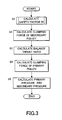
- FIG. 3 is a flowchart showing control of the belt type continuously variable transmission according to this embodiment.
- FIG. 4 is a map showing a relationship between a pulley ratio and a balance thrust ratio.
- FIG. 5 is a flowchart showing control of the belt type continuously variable transmission according to this embodiment.
- FIG. 6 is a map showing a relationship between the pulley ratio and a safety factor.
- FIG. 7 is a time chart showing actions of the belt type continuously variable transmission according to this embodiment.
- FIG. 1 is a schematic constitutional diagram showing a line pressure control device of a belt type continuously variable transmission according to this embodiment.
- a belt type continuously variable transmission 10 comprises a primary pulley 11 , a secondary pulley 12 , a V belt 13 , a CVT control unit 20 (to be referred to as a “CVTCU” hereafter), and a hydraulic control unit 30 .
- the primary pulley 11 is an input shaft side pulley that inputs a rotation of an engine 1 into the belt type continuously variable transmission 10 .
- the primary pulley 11 includes a fixed conical plate 11 b that rotates integrally with an input shaft 11 d , and a movable conical plate 11 a that is disposed opposite the fixed conical plate 11 b so as to form a V-shaped pulley groove and can be displaced in an axial direction by an oil pressure acting on a primary pulley cylinder chamber 11 c .
- the primary pulley 11 is connected to the engine 1 via a forward-reverse change-over mechanism 3 and a torque converter 2 having a lockup clutch, and inputs the rotation of the engine 1 .
- a rotation speed of the primary pulley 11 is detected by a primary pulley rotation speed sensor 26 .
- the V belt 13 is wound around the primary pulley 11 and the secondary pulley 12 , and transmits a rotation of the primary pulley 11 to the secondary pulley 12 .
- the secondary pulley 12 outputs the rotation transmitted thereto by the V belt 13 to a differential 4 .
- the secondary pulley 12 includes a fixed conical plate 12 b that rotates integrally with an output shaft 12 d , and a movable conical plate 12 a that is disposed opposite the fixed conical plate 12 b so as to form a V-shaped pulley groove and can be displaced in the axial direction in accordance with an oil pressure acting on a secondary pulley cylinder chamber 12 c .
- a pressure receiving surface area of the secondary pulley cylinder chamber 12 c is set to be substantially equal to the pressure receiving surface area of the primary pulley cylinder chamber 11 c.
- the secondary pulley 12 is connected to the differential 4 via an idler gear 14 and an idler shaft, and outputs the transmitted rotation to the differential 4 .
- a rotation speed of the secondary pulley 12 is detected by a secondary pulley rotation speed sensor 27 .
- a vehicle speed can be calculated from the rotation speed of the secondary pulley 12 .
- the CVTCU 20 determines a shift ratio and a contact frictional force on the basis of signals from an inhibitor switch 23 , an accelerator pedal stroke sensor 24 , an oil temperature sensor 25 , the primary pulley rotation speed sensor 26 , the secondary pulley rotation speed sensor 27 , and so on and input torque information from an engine control unit 21 , and transmits a command to the hydraulic control unit 30 to control the belt type continuously variable transmission 10 .
- the hydraulic control unit 30 operates in response to a command from the CVTCU 20 .
- the hydraulic control unit 30 moves the movable conical plate 11 a and the movable conical plate 12 a in a rotary axis direction by controlling the oil pressure supplied to the primary pulley 11 and secondary pulley 12 .
- the rotation of the engine 1 is input into the belt type continuously variable transmission 10 via the torque converter 2 and the forward-reverse change-over mechanism 3 and then transmitted from the primary pulley 11 to the differential 4 via the V belt 13 and the secondary pulley 12 .
- the movable conical plate 11 a of the primary pulley 11 and the movable conical plate 12 a of the secondary pulley 12 are displaced in the axial direction such that the contact radius thereof with the V belt 13 is modified, and as a result, the shift ratio is varied continuously.
- FIG. 2 is a schematic diagram showing the hydraulic control unit and the CVTCU.
- the hydraulic control unit 30 includes a regulator valve 31 , a shift control valve 32 , and a pressure reducing valve 33 , and controls an oil pressure supplied from a hydraulic pump 34 before supplying the oil pressure to the primary pulley 11 and secondary pulley 12 .
- the regulator valve 31 is a pressure regulating valve that includes a solenoid and regulates the pressure of the oil pumped from the hydraulic pump 34 to a predetermined line pressure in accordance with a command (a duty signal or the like, for example) from the CVTCU 20 .
- the line pressure supplied by the hydraulic pump 34 and regulated by the regulator valve 31 is supplied to the shift control valve 32 and the pressure reducing valve 33 , respectively.
- the shift control valve 32 is a control valve that controls an oil pressure of the primary pulley cylinder chamber 11 c (to be referred to as a “primary pressure” hereafter) to a desired target pressure.
- the shift control valve 32 is connected to a servo link 50 constituting a mechanical feedback mechanism such that the shift control valve 32 is driven by a step motor 40 connected to one end of the servo link 50 and receives feedback relating to the groove width, or in other words an actual shift ratio, from the movable conical plate 11 a of the primary pulley 11 , which is connected to the other end of the servo link 50 .
- the shift control valve 32 performs oil pressure intake and discharge to and from the primary pulley cylinder chamber 11 c in accordance with a displacement of a spool 32 a , thereby regulating the primary pressure such that a target shift ratio indicated by a drive position of the step motor 40 is achieved, and when a shift is actually completed, the shift control valve 32 receives a displacement from the servo link 50 to hold the spool 32 a in a closed position.
- the pressure reducing valve 33 is a control valve that includes a solenoid and controls a pressure (to be referred to hereafter as a “secondary pressure”) supplied to the secondary pulley cylinder chamber 12 c to a desired target pressure.
- the shift ratio of the primary pulley 11 and secondary pulley 12 is controlled by the step motor 40 , which is driven in accordance with a shift command signal from the CVTCU 20 , and the spool 32 a of the shift control valve 32 is driven in accordance with the displacement of the servo link 50 , which operates in response to the step motor 40 .
- the line pressure supplied to the shift control valve 32 is regulated such that the primary pressure is supplied to the primary pulley 11 , and as a result, the groove width is controlled variably and set at a predetermined shift ratio.
- the CVTCU 20 reads a range signal from the inhibitor switch 23 , an accelerator pedal stroke from the accelerator pedal stroke sensor 24 , an oil temperature of the belt type continuously variable transmission 10 from the oil temperature sensor 25 , signals from the primary pulley speed sensor 26 , the secondary pulley speed sensor 27 , an oil pressure sensor 29 , and so on in order to control the shift ratio and the contact frictional force of the V belt 13 variably.
- the oil pressure sensor 29 detects the secondary pressure applied to the cylinder chamber 12 c of the secondary pulley.
- a target value of the line pressure is determined from the input torque information, the speed ratio, and the oil temperature, whereupon the line pressure is controlled by driving the solenoid of the regulator valve 31 . Further, a target value of the secondary pressure is determined, whereupon the solenoid of the pressure reducing valve 33 is driven in accordance with a detection value of the oil pressure sensor 29 and the target value, and thus the secondary pressure is controlled by feedback control.
- FIG. 3 is a flowchart showing control for calculating the primary pressure and secondary pressure, which is executed repeatedly at predetermined short time intervals (of 10 ms, for example).
- a safety factor Sf is calculated.
- the safety factor Sf is a value used when calculating a clamping force Fzs of the secondary pulley 12 , and is set as a margin of the clamping force Fzs of the secondary pulley 12 .
- a method of calculating the safety factor Sf will be described below.
- a step S 2 the clamping force Fzs of the secondary pulley 12 is calculated on the basis of the safety factor Sf set in the step S 1 .
- the clamping force Fzs of the secondary pulley 12 is calculated on the basis of a following Equation (1).
- Tin is the torque input into the primary pulley 11
- ⁇ is a semi-vertex angle (sheave angle) of the pulleys 11 , 12
- Rp is a belt winding radius of the primary pulley 11
- ⁇ is a frictional coefficient between the belt 13 and the pulleys 11 , 12 .
- the belt winding radius Rp of the primary pulley 11 is calculated on the basis of a pulley ratio Ip, a belt circumference, and an inter-axial distance between the pulleys, the latter two taking fixed values.
- a balance thrust ratio Fzp/Fzs is calculated.
- the balance thrust ratio Fzp/Fzs is a ratio of a clamping force Fzp of the primary pulley 11 to the clamping force Fzs of the secondary pulley 12 , which is calculated on the basis of a map shown in FIG. 4 as a value required to maintain the pulley ratio Ip in a state of equilibrium.
- FIG. 4 is a map showing a relationship between the pulley ratio Ip and the balance thrust ratio Fzp/Fzs, on which the balance thrust ratio Fzp/Fzs is set steadily lower as the pulley ratio Ip increases and set lower than 1.0 on a Low side.
- the primary clamping force Fzp is calculated.
- the primary clamping force Fzp is calculated by multiplying the balance thrust ratio Fzp/Fzs by the secondary clamping force Fzs. Further, during an upshift, the primary clamping force Fzp is calculated by further adding thereto a differential thrust set on the basis of a target shift speed.
- the differential thrust is a force for achieving the target shift ratio.
- a step S 5 the primary pressure and secondary pressure are calculated on the basis of the primary clamping force Fzp and secondary clamping force Fzs.
- FIG. 5 is a flowchart showing control for calculating the safety factor Sf, which is executed repeatedly at predetermined short time intervals (of 10 ms, for example).
- the routine advances to a step S 13 , and when it is determined that an upshift command has not been output, the routine advances to a step S 12 .
- an upshift command is output when a target pulley ratio is lower than the current pulley ratio Ip, and is output continuously until a series of shift operations is complete.
- the safety factor Sf is set at a fixed predetermined value, whereupon the processing is terminated.
- FIG. 6 is a map showing a relationship between the pulley ratio Ip and the safety factor Sfv, on which a broken line indicates the conventional (fixed value) safety factor Sf.
- the safety factor Sfv is set to be lower as the pulley ratio Ip increases and to remain constant at or above a predetermined pulley ratio Ip.
- the predetermined pulley ratio Ip is set at the pulley ratio Ip when the balance thrust ratio Fzp/Fzs is 0.9, for example.
- a reduction ratio of an engine rotation speed is calculated.
- the reduction rate of the engine rotation speed is calculated by comparing the current engine rotation speed with the engine rotation speed during the previous control, for example.
- the pulley ratio Ip decreases, and therefore the engine rotation speed decreases such that the reduction rate of the engine rotation speed takes a positive value.
- the routine advances to a step S 16 , and when the reduction rate is equal to or larger than the predetermined reduction rate, the routine advances to a step S 17 .
- the predetermined reduction rate is set at a value at which the possibility of slippage of the belt 13 caused by insufficient secondary pressure can be determined, this value being determined in advance through experiment or the like.
- step S 16 a small value ⁇ is added to the safety factor Sfv to obtain a new safety factor Sfv.
- the safety factor Sfv set in the steps S 13 to S 16 is set as the safety factor Sf.
- a step S 18 the safety factor Sf is output after a dead period, whereupon the processing is terminated.
- a delay occurs between output of the upshift command and modification of the actual pulley ratio Ip, and therefore this delay is determined in advance as a dead period through experiment or the like, and the safety factor Sf is output following the elapse of the dead period.
- the safety factor Sf set in the step S 12 continues to be output until the dead period has elapsed, even after the upshift command is output.
- the safety factor Sf during an upshift is set at a lower value than the safety factor Sf when the pulley ratio Ip is in a steady state, and as a result, the secondary clamping force Fzs and the primary clamping force Fzp obtained by adding the differential thrust to the secondary clamping force Fzs are controlled to lower values than the values thereof in a steady state. Reduction of the safety factor Sf during an upshift will now be described in further detail.
- Equation (1) for calculating the secondary clamping force Fzs is subjected to time differentiation, a following Equation (2) is obtained.
- the secondary clamping force Fzs is a decreasing function relating to the belt winding radius Rp of the primary pulley 11 . More specifically, during an upshift, in which the belt winding radius Rp of the primary pulley 11 increases, the secondary clamping force Fzs decreases. Hence, during an upshift, the safety factor Sf can be set at a lower value than the value thereof in a steady state.
- the balance thrust ratio Fzp/Fzs is small and the secondary clamping force is greater than the primary clamping force. Furthermore, during a Low period, a belt winding radius Rs of the secondary pulley 12 is larger than the belt winding radius Rp of the primary pulley 11 . Hence, if belt slippage occurs during a Low period, the belt slippage occurs on the primary pulley side.
- the safety factor Sf during an upshift can be set at a lower value than the safety factor Sf in a steady state, and moreover, the safety factor Sf can be set at a steadily lower value as the pulley ratio Ip shifts toward the Low side.
- FIG. 7 is a time chart illustrating actions of the belt type continuously variable transmission according to this embodiment.
- (a) shows the upshift command
- (b) shows the pulley ratio Ip
- (c) shows the safety factor Sf
- (d) shows the secondary clamping force
- (e) shows the engine rotation speed.
- Broken lines in (c) and (d) indicate variation in the conventional example.
- the upshift command is output at a time t1, whereupon the safety factor Sf is set at a lower value than the value thereof in a steady state by referring to the map.
- the safety factor Sf is output at a time t2, whereupon the secondary clamping force is calculated on the basis of the safety factor Sf.
- the secondary clamping force takes a lower value than that of the conventional example indicated by the broken line.
- the engine rotation speed As the pulley ratio Ip decreases, the engine rotation speed also decreases, and at a time t3, the secondary clamping force becomes insufficient such that the reduction rate of the engine rotation speed is determined to be lower than the predetermined reduction rate. Therefore, the small value ⁇ is added to the safety factor Sf until the reduction rate of the engine rotation speed rises to or above the predetermined reduction rate. As a result, the secondary clamping force rises, thereby preventing slippage of the belt 13 .
- the safety factor Sf is returned to the pre-shift fixed predetermined value.
- the safety factor Sf is looked up on the map and set at a lower value than the value thereof in a steady state, and therefore, during an upshift, when it is possible to reduce the pulley clamping force required to hold the belt, the pulley clamping force can be set at a lower value, thereby reducing the pulley thrust within a range in which belt slippage does not occur.
- the secondary pressure and the differential thrust-adjusted primary pressure decrease, and as a result, the line pressure can be reduced, enabling a reduction in the load of the hydraulic pump 34 and an improvement in fuel efficiency.
- the secondary clamping force is set at a lower value during an upshift such that a thrust difference is generated between the secondary clamping force and the primary clamping force, and therefore an improvement in shift responsiveness can be achieved during an upshift. More specifically, during an upshift, the target shift speed is achieved by adding the differential thrust to the primary clamping force, and since the secondary clamping force is set at a lower value, a thrust difference can be generated easily, enabling a corresponding improvement in shift responsiveness.
- the safety factor Sf is set steadily lower as the pulley ratio Ip upon output of the upshift command increases (i.e. shifts further toward the Low side).
- the safety factor Sf can be set lower and the secondary pressure can be reduced further, and as a result, a further improvement in fuel efficiency can be achieved while preventing belt slippage.
- the safety factor Sf can be set at a minimum value, enabling a further improvement in fuel efficiency.
- the safety factor Sf is increased, and therefore, in cases where the safety factor Sf is reduced excessively, the secondary pressure can be corrected to a higher side by detecting a racing tendency in the engine 1 . As a result, belt slippage can be prevented even more reliably.
Landscapes
- Engineering & Computer Science (AREA)
- General Engineering & Computer Science (AREA)
- Mechanical Engineering (AREA)
- Control Of Transmission Device (AREA)
Abstract
Description
Claims (12)
Applications Claiming Priority (2)
| Application Number | Priority Date | Filing Date | Title |
|---|---|---|---|
| JP2009071402A JP4889757B2 (en) | 2009-03-24 | 2009-03-24 | Belt-type continuously variable transmission and its shift control method |
| JP2009-71402 | 2009-03-24 |
Publications (2)
| Publication Number | Publication Date |
|---|---|
| US20100248874A1 US20100248874A1 (en) | 2010-09-30 |
| US8412636B2 true US8412636B2 (en) | 2013-04-02 |
Family
ID=42273612
Family Applications (1)
| Application Number | Title | Priority Date | Filing Date |
|---|---|---|---|
| US12/720,473 Expired - Fee Related US8412636B2 (en) | 2009-03-24 | 2010-03-09 | Belt type continuously variable transmission and control method thereof |
Country Status (5)
| Country | Link |
|---|---|
| US (1) | US8412636B2 (en) |
| EP (1) | EP2233792B1 (en) |
| JP (1) | JP4889757B2 (en) |
| KR (1) | KR101682712B1 (en) |
| CN (1) | CN101846164B (en) |
Cited By (4)
| Publication number | Priority date | Publication date | Assignee | Title |
|---|---|---|---|---|
| US9777835B2 (en) | 2015-07-06 | 2017-10-03 | Toyota Motor Engineering & Manufacturing North America, Inc. | System and method for determining whether a CVT is set to a maximum gear ratio at vehicle startup |
| US9958062B2 (en) * | 2014-03-27 | 2018-05-01 | Jatco Ltd | Control device for continuously variable transmission |
| US10316968B2 (en) * | 2017-05-16 | 2019-06-11 | GM Global Technology Operations LLC | Method and apparatus for ratio control for a continuously variable transmission |
| US20200173552A1 (en) * | 2017-08-23 | 2020-06-04 | Nissan Motor Co., Ltd. | Control method and control device for continuously variable transmission |
Families Citing this family (19)
| Publication number | Priority date | Publication date | Assignee | Title |
|---|---|---|---|---|
| KR20120107641A (en) | 2011-03-22 | 2012-10-04 | 현대자동차주식회사 | Clamp force control method for continuous variable transmission |
| WO2013088880A1 (en) * | 2011-12-13 | 2013-06-20 | ジヤトコ株式会社 | Continuously variable transmission and method for controlling continuously variable transmission |
| JP5934342B2 (en) * | 2012-03-28 | 2016-06-15 | ジヤトコ株式会社 | Continuously variable transmission and hydraulic control method thereof |
| WO2014125695A1 (en) * | 2013-02-13 | 2014-08-21 | 本田技研工業株式会社 | Controller for continuously variable transmission |
| JP5941882B2 (en) * | 2013-08-08 | 2016-06-29 | ジヤトコ株式会社 | Shift control device for continuously variable transmission |
| JP2015081644A (en) * | 2013-10-23 | 2015-04-27 | トヨタ自動車株式会社 | Control unit for non-stage transmission |
| EP3061996B8 (en) * | 2013-10-23 | 2018-06-06 | Jatco Ltd | Control device for continuously variable transmission |
| JP5937628B2 (en) * | 2014-01-17 | 2016-06-22 | ジヤトコ株式会社 | Continuously variable transmission and its safety factor correction method |
| US9765884B2 (en) * | 2015-11-09 | 2017-09-19 | GM Global Technology Operations LLC | Method and apparatus to control a continuously variable transmission |
| JP6452668B2 (en) * | 2016-12-09 | 2019-01-16 | 本田技研工業株式会社 | Shift control method for belt type continuously variable transmission |
| US10161517B1 (en) * | 2017-06-07 | 2018-12-25 | GM Global Technology Operations LLC | Method and apparatus to control a continuously variable transmission |
| JP6990323B2 (en) * | 2018-10-22 | 2022-01-12 | ジヤトコ株式会社 | Continuously variable transmission |
| US11835134B2 (en) * | 2018-10-22 | 2023-12-05 | Jatco Ltd | Continuously variable transmission |
| CN112639330B (en) * | 2018-10-22 | 2024-12-13 | 加特可株式会社 | Continuously variable transmission for vehicles |
| US11738752B2 (en) * | 2019-06-24 | 2023-08-29 | Jatco Ltd | Control device for vehicle and control method for vehicle |
| US11644094B2 (en) * | 2020-01-23 | 2023-05-09 | Kawasaki Motors, Ltd. | Power unit |
| JP7412590B2 (en) * | 2020-11-02 | 2024-01-12 | ジヤトコ株式会社 | Damping pressure supply circuit for pulley pressure control valve |
| JP7691485B2 (en) * | 2021-02-18 | 2025-06-11 | ジヤトコ株式会社 | Continuously variable transmission, control method and program for continuously variable transmission |
| RU2759535C1 (en) * | 2021-06-03 | 2021-11-15 | Федеральное государственное автономное образовательное учреждение высшего образования «Северный (Арктический) федеральный университет имени М. В. Ломоносова» | Apparatus for increasing the traction force of the pulley of a band saw machine |
Citations (8)
| Publication number | Priority date | Publication date | Assignee | Title |
|---|---|---|---|---|
| JPS61132428A (en) | 1984-11-30 | 1986-06-19 | Mazda Motor Corp | Line pressure control device in stepless speed change unit |
| JPH1030698A (en) | 1996-07-16 | 1998-02-03 | Nissan Motor Co Ltd | V-belt type continuously variable transmission |
| US20030050149A1 (en) | 2001-09-12 | 2003-03-13 | Jatco Ltd | Hydraulic pressure control system for belt-type continuously variable transmission |
| JP2004084749A (en) | 2002-08-26 | 2004-03-18 | Jatco Ltd | Control device of continuously variable transmission |
| JP2004316799A (en) | 2003-04-17 | 2004-11-11 | Toyota Motor Corp | Control device for continuously variable transmission |
| US20060069486A1 (en) * | 2004-09-24 | 2006-03-30 | Jatco Ltd. | Belt type continuously variable transmission |
| US20070117663A1 (en) | 2003-12-01 | 2007-05-24 | Van Der Leest Adrianus Johanne | Continuously variable transmission |
| US20070232423A1 (en) * | 2006-03-17 | 2007-10-04 | Jatco Ltd | Hydraulic control apparatus and method for belt-type continuously-variable transmission |
-
2009
- 2009-03-24 JP JP2009071402A patent/JP4889757B2/en not_active Expired - Fee Related
-
2010
- 2010-02-15 EP EP10001545A patent/EP2233792B1/en not_active Not-in-force
- 2010-03-09 US US12/720,473 patent/US8412636B2/en not_active Expired - Fee Related
- 2010-03-22 CN CN201010144482.XA patent/CN101846164B/en not_active Expired - Fee Related
- 2010-03-23 KR KR1020100025521A patent/KR101682712B1/en not_active Expired - Fee Related
Patent Citations (10)
| Publication number | Priority date | Publication date | Assignee | Title |
|---|---|---|---|---|
| JPS61132428A (en) | 1984-11-30 | 1986-06-19 | Mazda Motor Corp | Line pressure control device in stepless speed change unit |
| JPH1030698A (en) | 1996-07-16 | 1998-02-03 | Nissan Motor Co Ltd | V-belt type continuously variable transmission |
| EP0850372A1 (en) | 1996-07-16 | 1998-07-01 | Nissan Motor Company, Limited | Continuously variable transmission |
| US6050912A (en) | 1996-07-16 | 2000-04-18 | Nissan Motor Co., Ltd. | Continuously variable transmission that changes axial thurst based on transmission ratio |
| US20030050149A1 (en) | 2001-09-12 | 2003-03-13 | Jatco Ltd | Hydraulic pressure control system for belt-type continuously variable transmission |
| JP2004084749A (en) | 2002-08-26 | 2004-03-18 | Jatco Ltd | Control device of continuously variable transmission |
| JP2004316799A (en) | 2003-04-17 | 2004-11-11 | Toyota Motor Corp | Control device for continuously variable transmission |
| US20070117663A1 (en) | 2003-12-01 | 2007-05-24 | Van Der Leest Adrianus Johanne | Continuously variable transmission |
| US20060069486A1 (en) * | 2004-09-24 | 2006-03-30 | Jatco Ltd. | Belt type continuously variable transmission |
| US20070232423A1 (en) * | 2006-03-17 | 2007-10-04 | Jatco Ltd | Hydraulic control apparatus and method for belt-type continuously-variable transmission |
Cited By (5)
| Publication number | Priority date | Publication date | Assignee | Title |
|---|---|---|---|---|
| US9958062B2 (en) * | 2014-03-27 | 2018-05-01 | Jatco Ltd | Control device for continuously variable transmission |
| US9777835B2 (en) | 2015-07-06 | 2017-10-03 | Toyota Motor Engineering & Manufacturing North America, Inc. | System and method for determining whether a CVT is set to a maximum gear ratio at vehicle startup |
| US10316968B2 (en) * | 2017-05-16 | 2019-06-11 | GM Global Technology Operations LLC | Method and apparatus for ratio control for a continuously variable transmission |
| US20200173552A1 (en) * | 2017-08-23 | 2020-06-04 | Nissan Motor Co., Ltd. | Control method and control device for continuously variable transmission |
| US10982764B2 (en) * | 2017-08-23 | 2021-04-20 | Nissan Motor Co., Ltd. | Control method and control device for continuously variable transmission |
Also Published As
| Publication number | Publication date |
|---|---|
| KR20100106928A (en) | 2010-10-04 |
| EP2233792A3 (en) | 2011-09-14 |
| JP4889757B2 (en) | 2012-03-07 |
| EP2233792A2 (en) | 2010-09-29 |
| JP2010223336A (en) | 2010-10-07 |
| US20100248874A1 (en) | 2010-09-30 |
| CN101846164A (en) | 2010-09-29 |
| CN101846164B (en) | 2014-05-28 |
| KR101682712B1 (en) | 2016-12-05 |
| EP2233792B1 (en) | 2012-10-17 |
Similar Documents
| Publication | Publication Date | Title |
|---|---|---|
| US8412636B2 (en) | Belt type continuously variable transmission and control method thereof | |
| KR101363307B1 (en) | Variable Speed Control Device for Belt Type Continuously Variable Transmission | |
| US8352134B2 (en) | Controller for vehicle continuously variable transmission | |
| JP5435137B2 (en) | Control device for continuously variable transmission for vehicle | |
| US7998006B2 (en) | Speed ratio control device and method for belt type continuously variable transmission | |
| JP4034148B2 (en) | Belt type continuously variable transmission | |
| JP4755970B2 (en) | Shift control device for belt type continuously variable transmission | |
| US7140991B2 (en) | Shift control system, and control apparatus and method for belt-type continuously variable transmission | |
| US7039516B2 (en) | Belt type continuously variable transmission | |
| JP4072200B2 (en) | Control device for belt type continuously variable transmission | |
| JP3905445B2 (en) | Hydraulic control device for V-belt type continuously variable transmission | |
| US7384372B2 (en) | Pulley thrust control device for continuously variable transmission | |
| JP4124625B2 (en) | Control device for continuously variable transmission | |
| JP4212541B2 (en) | Control device for continuously variable transmission | |
| JP4141377B2 (en) | Belt type continuously variable transmission | |
| JP4660450B2 (en) | Line pressure control device for belt type continuously variable transmission |
Legal Events
| Date | Code | Title | Description |
|---|---|---|---|
| AS | Assignment |
Owner name: JATCO LTD, JAPAN Free format text: ASSIGNMENT OF ASSIGNORS INTEREST;ASSIGNOR:KATOU, YOSHIAKI;REEL/FRAME:024065/0842 Effective date: 20100121 |
|
| FEPP | Fee payment procedure |
Free format text: PAYOR NUMBER ASSIGNED (ORIGINAL EVENT CODE: ASPN); ENTITY STATUS OF PATENT OWNER: LARGE ENTITY |
|
| STCF | Information on status: patent grant |
Free format text: PATENTED CASE |
|
| AS | Assignment |
Owner name: NISSAN MOTOR CO., LTD., JAPAN Free format text: ASSIGNOR ASSIGNS 50% INTEREST;ASSIGNOR:JATCO LTD;REEL/FRAME:032018/0901 Effective date: 20131224 Owner name: JATCO LTD, JAPAN Free format text: ASSIGNOR ASSIGNS 50% INTEREST;ASSIGNOR:JATCO LTD;REEL/FRAME:032018/0901 Effective date: 20131224 |
|
| FPAY | Fee payment |
Year of fee payment: 4 |
|
| FEPP | Fee payment procedure |
Free format text: MAINTENANCE FEE REMINDER MAILED (ORIGINAL EVENT CODE: REM.); ENTITY STATUS OF PATENT OWNER: LARGE ENTITY |
|
| LAPS | Lapse for failure to pay maintenance fees |
Free format text: PATENT EXPIRED FOR FAILURE TO PAY MAINTENANCE FEES (ORIGINAL EVENT CODE: EXP.); ENTITY STATUS OF PATENT OWNER: LARGE ENTITY |
|
| STCH | Information on status: patent discontinuation |
Free format text: PATENT EXPIRED DUE TO NONPAYMENT OF MAINTENANCE FEES UNDER 37 CFR 1.362 |
|
| FP | Lapsed due to failure to pay maintenance fee |
Effective date: 20210402 |