WO2014162772A1 - アングル工具及び電動工具 - Google Patents
アングル工具及び電動工具 Download PDFInfo
- Publication number
- WO2014162772A1 WO2014162772A1 PCT/JP2014/052678 JP2014052678W WO2014162772A1 WO 2014162772 A1 WO2014162772 A1 WO 2014162772A1 JP 2014052678 W JP2014052678 W JP 2014052678W WO 2014162772 A1 WO2014162772 A1 WO 2014162772A1
- Authority
- WO
- WIPO (PCT)
- Prior art keywords
- brushless motor
- switch
- motor
- shaft
- housing
- Prior art date
- Legal status (The legal status is an assumption and is not a legal conclusion. Google has not performed a legal analysis and makes no representation as to the accuracy of the status listed.)
- Ceased
Links
Images


Classifications
-
- B—PERFORMING OPERATIONS; TRANSPORTING
- B25—HAND TOOLS; PORTABLE POWER-DRIVEN TOOLS; MANIPULATORS
- B25F—COMBINATION OR MULTI-PURPOSE TOOLS NOT OTHERWISE PROVIDED FOR; DETAILS OR COMPONENTS OF PORTABLE POWER-DRIVEN TOOLS NOT PARTICULARLY RELATED TO THE OPERATIONS PERFORMED AND NOT OTHERWISE PROVIDED FOR
- B25F5/00—Details or components of portable power-driven tools not particularly related to the operations performed and not otherwise provided for
-
- H—ELECTRICITY
- H02—GENERATION; CONVERSION OR DISTRIBUTION OF ELECTRIC POWER
- H02K—DYNAMO-ELECTRIC MACHINES
- H02K7/00—Arrangements for handling mechanical energy structurally associated with dynamo-electric machines, e.g. structural association with mechanical driving motors or auxiliary dynamo-electric machines
- H02K7/14—Structural association with mechanical loads, e.g. with hand-held machine tools or fans
- H02K7/145—Hand-held machine tool
-
- H—ELECTRICITY
- H02—GENERATION; CONVERSION OR DISTRIBUTION OF ELECTRIC POWER
- H02K—DYNAMO-ELECTRIC MACHINES
- H02K5/00—Casings; Enclosures; Supports
- H02K5/04—Casings or enclosures characterised by the shape, form or construction thereof
Definitions
- the present invention relates to an angle tool having an output shaft arranged at an angle with respect to a motor shaft, and an electric tool having an output shaft.
- an electric drill in which a bit rotates around an axis that intersects the rotation axis of a motor.
- the motor of this electric drill has a commutator on the rotating shaft side that can come into contact with the brush of the stator in order to rotate the rotor by switching the direction of the current flowing in the coil of the rotor.
- the brush gradually wears due to contact with the rotating commutator, and eventually the current is not sufficiently passed, so that the power drill is provided with a brush replacement protrusion or lid.
- the conventional electric drill as described above has a commutator and a brush to rotate the rotating shaft of the motor, it is necessary to provide a protrusion and a lid for replacing the brush, and accordingly, it becomes less compact.
- the motor does not rotate until the brush is replaced with a new brush, and the bit cannot be rotated, and the electric drill cannot be used.
- the brush needs to be replaced, which takes time. Therefore, the main object of the present invention is to provide an angle tool that is more compact and easy to grip, requires less maintenance, and prevents the occurrence of an unusable period.
- a first aspect of the present invention is directed to a brushless motor having a motor shaft, a switch for energizing the brushless motor, and rotation of the brushless motor transmitted to the motor shaft. And an output shaft having an angle, a housing for housing the brushless motor and the switch, and a sensor substrate for detecting rotation of the motor shaft, and the sensor substrate on the brushless motor. It is characterized by fixing.
- a brushless motor having a motor shaft, a switch for energizing the brushless motor, an output shaft that is transmitted with rotation of the brushless motor and has an angle with respect to the motor shaft.
- a housing for housing the brushless motor and the switch, and a battery fixed to the housing, and the switch is disposed between the battery and the brushless motor. It is.
- a brushless motor having a motor shaft, a switch for energizing the brushless motor, an output shaft which is transmitted with rotation of the brushless motor and has an angle with respect to the motor shaft.
- a brushless motor having a rotor including a motor shaft and a stator, a motor shaft fixed to the rotor, a fan fixed to the motor shaft, and the brushless motor are energized.
- a switch for transmitting rotation of the brushless motor, an output shaft having an angle with respect to the motor shaft, a housing for housing the brushless motor and the switch, and a sensor for detecting rotation of the rotor And the stator is arranged between the sensor substrate and the switch.
- the invention according to claim 5 is a brushless motor having a rotor including a motor shaft and a stator, a fan fixed to the motor shaft, a switch for energizing the brushless motor, and rotation of the brushless motor.
- the invention according to claim 6 is a brushless motor having a stator and a rotor, a motor shaft fixed to the rotor, a fan fixed to the motor shaft, a switch for energizing the brushless motor, An output shaft that is transmitted with the rotation of the brushless motor and has an angle with respect to the motor shaft, a housing that houses the brushless motor and the switch, a control circuit board that is housed in the housing, and the stator And a plurality of switching elements electrically connected to each other, and the switch is provided between the control circuit board and the plurality of switching elements.
- the invention according to claim 7 is a brushless motor having a stator and a rotor, a motor shaft fixed to the rotor, a fan fixed to the motor shaft, a switch for energizing the brushless motor, It has an output shaft to which the rotation of the brushless motor is transmitted, and a housing that houses the brushless motor and the switch, and the switch, the brushless motor, and the output shaft are arranged in a straight line. It is what.
- the rotation state of the motor shaft can be reliably detected with an efficient configuration, and the sensor can be more compact. It can be configured so that it can be easily gripped, and the maintenance work is reduced, thereby preventing the occurrence of an unusable period.
- the switch since the switch is arranged between the battery and the brushless motor, it is easy to route the wiring, and even if a load is applied, it can be made difficult to be disconnected, and more compact. It can be configured to be easily gripped, and the maintenance work is reduced, so that an unusable period can be prevented.
- the switch since the switch is arranged between the control circuit board and the brushless motor, the wiring is easy to perform and the resistance to heat is further improved, so that the operation of the brushless motor 216 is further improved. It can be made reliable, can be configured to be more compact and easy to grip, and further requires less maintenance, thereby preventing the occurrence of an inoperable period.
- the stator of the brushless motor since the stator of the brushless motor is disposed between the sensor board and the switch, the flow of wind can be made smoother, and it can be configured more compactly and easily gripped. Furthermore, the maintenance time is small and the occurrence of an unusable period is prevented.
- the brushless motor stator is arranged between the fan and the switch, the cooling efficiency of the brushless motor becomes better, and it can be configured more compactly and easily gripped. Occurrence of unusable periods is prevented with less maintenance effort.
- the switch since the switch is disposed between the control circuit board and the switching element, the switching element and the control circuit board can be easily cooled, thereby realizing more reliable operation. In addition, it can be configured to be more compact and easy to grip, and further, the maintenance work is reduced and the occurrence of an unusable period is prevented.
- the switch since the switch, the brushless motor, and the output shaft are arranged in a straight line, the switch can be configured more compactly and easily gripped, and further, the maintenance work is less and the inoperable period is generated. Is prevented.
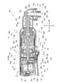
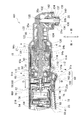
- FIG. 2 is an enlarged view of the front part of FIG. 1.
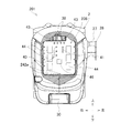
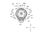
- FIG. 2 is a cross-sectional view taken along the line AA in FIG.
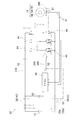
- FIG. 4 is a circuit diagram including a control circuit board of FIG. 3.
- FIG. 3 is a view corresponding to FIG. 1 according to a second embodiment of the present invention.
- FIG. 6 is a front enlarged view of FIG. 5.
- FIG. 6 is a sectional view taken along line BB in FIG. 5.
- FIG. 6 is a view corresponding to FIG. 1 according to a third embodiment of the present invention.
- FIG. 9 is an enlarged view of the front part of FIG. 8.
- FIG. 10 is a cross-sectional view taken along the line CC of FIG. 8 (FIG. 9).
- FIG. 5 is a diagram corresponding to FIG. 4 of the third embodiment. It is FIG. 1 equivalent view which concerns on the 4th form of this invention. It is a front enlarged view of FIG. FIG. 13 is a DD cross-sectional view of FIG. 12 (FIG. 13).
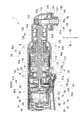
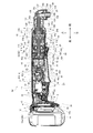
- FIG. 1 is a longitudinal center sectional view of an angle impact driver 1 which is an example of an angle type electric tool according to the first embodiment
- FIG. 2 is an enlarged front view of FIG. 1, and FIG. It is A sectional drawing.
- the angle type means that the motor shaft and the output shaft intersect at an angle of approximately 90 °.
- the right side in FIG. 1 is the front in the angle impact driver 1.
- the angle impact driver 1 has a housing 2 that forms the outline thereof.
- the housing 2 is formed so that it can be divided in half on the left and right sides, and the left and right portions are coupled to each other by a plurality of screws 3, 3... And corresponding cylindrical screw holes 4, 4.
- the housing 2 is formed in a cylindrical shape whose center axis is the front-rear direction.
- a battery mounting portion 12 to which the battery 10 can be attached is formed at the rear end portion of the housing 2.
- a switch 14 is accommodated in the rear portion of the housing 2 and in front of the battery mounting portion 12.
- a brushless motor 16 is accommodated in the center of the housing 2 and in front of the switch 14.
- a portion of the housing 2 from the battery mounting portion 12 to the outer front side of the brushless motor 16 is a main body housing 17.
- the main body of the angle impact driver 1 is formed by the main body housing 17 or a member accommodated therein.
- a driving force transmission mechanism 18 and an output shaft 20 are accommodated in the front portion of the housing 2 and in front of the brushless motor 16.
- a portion of the housing 2 that covers the driving force transmission mechanism 18 and the output shaft 20 is a metal hammer case 21 and a gear case 22 disposed in the front portion of the main body housing 12.
- the hammer case 21 is fixed to the gear case 22 by a fixing screw 21b.
- a hammer 93 and an anvil 94 described later are double-covered by the hammer case 21 and the gear case 22.
- a trigger-type switch lever 23 that can be pushed by a user with a finger or the like while being partially exposed from the housing 2 is provided below the switch 14.
- the forward / reverse reversing switch 24 for sequentially switching the rotation direction of the brushless motor 16 is accommodated in a state where it is partially exposed from the left and right side surfaces of the housing 2.
- the switch lever 23 is configured to be rotatable about the upper end 23a.
- the outer part of the rear part or the center part of the housing 2 (the outer part before the forward / reverse reversing switch 24 and after the outer side of the brushless motor 16) is formed as a grip to be gripped by the user.
- An anti-slip member (thermoplastic elastomer) is disposed on the grip.
- a light (LED) 26 that illuminates the front (near the lower end of the output shaft 20) is provided below the brushless motor 16.
- a hook 28 is attached to the rear side surface of the housing 2 with a screw 27 (FIG. 3).
- the battery 10 is a substantially rectangular parallelepiped rechargeable battery, and has lithium ion battery cells inside.
- the battery 10 has a detachable button 30 that can be pushed forward in the lower rear part (FIG. 3).
- the removal button 30 is urged rearward by an elastic body (spring), and is normally positioned along the other part of the battery 10.
- the battery 10 has a claw 32 that can protrude and retract with respect to the periphery of the battery 10 at the front lower portion. When the removal button 30 is in the normal position, the claw 32 is in a protruding state, and when the removal button 30 is pushed forward against the urging force, the claw 32 is in a buried state.
- the battery 10 has a terminal 33a on the front surface and two rails 10a and 10a extending vertically.
- the battery mounting portion 12 has a planar portion that extends in the vertical and horizontal directions, and an engaging recess 34 that is recessed forward with respect to the periphery is formed on the lower side of the planar portion.
- the battery mounting portion 12 has a rail engaging portion that engages with a corresponding rail 10a of the battery 10 on the rear surface, and also has a terminal 33b.
- a control circuit board 36 is disposed on the inner side (front side) of the battery mounting portion 12.
- Power supply leads 38 are provided between the control circuit board 36 and the switch 14 in front of the control circuit board 36.
- rotation control lead wires 40, 40... And a rotation detection signal lead wire 41 are provided between the control circuit board 36 and the light 26 in front of the control circuit board 36.
- Connectors 42c and 42d that can be coupled to each other are interposed between the lead wires 42a and 42b.
- the connectors 42c and 42d are attached in a coupled state in the rib 42e of the housing 2.
- the central portion of the write lead wire 42b is disposed above or in front of the outside of the motor housing 54 described later.
- power supply lead wires 43 and 43 are provided between the control circuit board 36 and the terminal 33 b of the battery mounting portion 12. Electricity at the terminal 33b of the battery mounting portion 12 is communicated to the switch 14 via the power supply lead wires 43 and 43, the control circuit board 36, and the power supply lead wires 38 and 38.
- a plurality (six) of switching elements 44, 44,... And a microcomputer 46 are mounted on the control circuit board 36.
- the switching elements 44, 44,... Are arranged so as to be divided into left and right and arranged in groups of three each. Three switching elements 44, 44... Are arranged on the left and right sides of the microcomputer 46.
- the switch 14 switches the energization state for the brushless motor 16 and is for energizing the brushless motor 16.
- the switch 14 has a switch body 50 and a plunger 51 that protrudes downward from the lower surface thereof. When the plunger 51 is pushed upward, the switch 14 is turned on. When the plunger 51 is not pushed and is in a normal position, the switch 14 is turned off. The rear portion of the switch lever 23 is in contact with the lower side of the plunger 51. Power supply leads 52 and 52 are provided between the switch 14 and a sensor board 80 (described later) fixed to the brushless motor 16 in front of the switch 14.
- the brushless motor 16 has a rotor 56 that is a rotor and a stator 58 that is a stator, and is accommodated inside the motor housing 54.
- the rotor 56 includes a motor shaft 60 that is a rotation shaft of the brushless motor 16, a front bearing 62 that supports the front portion of the motor shaft 60, a rear bearing 64 that supports the rear end portion of the motor shaft 60, and a motor shaft.
- 60 includes a rotor core (rotor core) and a magnet 66 provided integrally with the motor shaft 60 in the central portion of the motor 60.
- a fan 68 for discharging dust, heat and the like is integrally provided with the motor shaft 60 on the rear side of the front bearing 62.
- a pinion 69 is fixed to the front end portion of the motor shaft 60.
- the front bearing 62 is held at the rear center of the gear case 22, and the rear bearing 64 is held at the inner center of the rear end of the motor housing 54.
- the stator 58 includes a cylindrical stator core 70 whose axial direction is the front-rear direction, a disk-shaped first insulating member 72 disposed on the front side of the stator core (stator core) 70, and the rear side or stator core of the stator core 70.
- the rear surface of the second insulating member 74 is provided with a plurality of concave portions 78, 78,.
- a disc-shaped sensor substrate 80 is installed on the rear side of the second insulating member 74.
- the sensor substrate 80 is disposed so that the rear surface of the second insulating member 74 excluding the concave portions 78 and the corresponding portion of the substantially flat front surface of the sensor substrate 80 are in contact with each other.
- a gap is formed between 80.
- the upper end portion of the sensor substrate 80 protrudes upward from a hole formed in the rear upper portion of the motor housing 54 and is a portion to which the lead wires 40 and 41 and the power supply lead wires 52 are connected. Further, a hole through which the motor shaft 60 is passed is formed in the center portion of the sensor substrate 80.
- An air inlet (not shown) is formed in the body housing 17 outside the switch 14, and the outside air introduced from the air inlet into the housing 2 by the fan 68 is between the second insulating member 74 and the sensor substrate 80. It is possible to flow into the brushless motor 16 through the gap.
- An exhaust port (not shown) is formed in the main body housing 17 outside the fan 68.
- the sensor substrate 80 has a plurality (three in this case) of rotation detection elements 81, 81... (See FIG. 4) as rotation detection sensors.
- the rotation detection elements 81, 81,... Are arranged at equal intervals on the upper front surface of the sensor substrate 80.
- FIG. 4 shows a drive circuit 82 of the angle impact driver 1 including each switching element 44 and each rotation detection element 81.
- the drive circuit 82 includes a power supply circuit unit 83, a three-phase bridge circuit unit 84 including switching elements 44, 44,..., And a microcomputer 46 that controls the switching elements 44, 44,.
- the power supply circuit portion 83 is a portion that is mainly disposed on the control circuit board 36 and that suppresses voltage fluctuations in the power supplied from the battery 10 via the terminals 33a and 33b. , And a power supply smoothing capacitor 85 connected in parallel to the power supply leads 38, 43,.
- the three-phase bridge circuit portion 84 is a portion disposed on the control circuit board 36 and is connected to the power supply leads 38, 43... In parallel with the power supply smoothing capacitor 85, and the pair of switching elements 44. , 44 have three output lines extending from each of them. Each output line is connected to a corresponding coil 76 in the stator 58 of the brushless motor 16 via the lead wire 40 or the sensor substrate 80.
- An example of each switching element 44 is a field effect transistor (FET).
- the microcomputer 46 arranged on the control circuit board 36 receives the rotation detection signals transmitted from the respective rotation detection elements 81 arranged on the sensor board 80 by means of the lead wires 41, 41,. 81, 81...
- Each rotation detection element 81 detects the position of the magnetic pole of the rotor 56 and transmits it as a rotation detection signal.
- Each lead 41 is output from the sensor board 80 to the control circuit board 36. It is wiring.
- the microcomputer 46 acquires the rotation state (rotation angle from the reference position) of the rotor 56 by grasping and synthesizing the rotation detection signals indicating the position of the magnetic pole of the rotor 56 transmitted from each rotation detection element 81. It is possible.
- the microcomputer 46 controls on / off of the switching elements 44, 44,... In the three-phase bridge circuit unit 84 according to the acquired rotation state of the rotor 56 (according to the state of each received rotation detection signal).
- Drive signals 89, 89,... (Collectively represented by one white arrow in FIG. 4) are output to the corresponding switching elements 44.
- the control circuit board 36 includes at least one of the microcomputer 46 and the switching elements 44, 44... (Three-phase bridge circuit section 84)
- the control circuit board 36 is a board that controls the brushless motor 16.
- Various elements and lead wires on the sensor substrate 80 are mounted in a state in which the amount of protrusion from the surface (the rear surface of the sensor substrate 80) is suppressed by a reflow method or the like (surface mount, SMT: Surface Mount Technology).
- a reflow method solder printing according to a predetermined pattern is applied to the sensor substrate 80 (or adhesive is applied to a component mounting position by a dispenser), various elements and lead wires are placed by a chip mounter, and the reflow furnace is used. This is a method in which the solder is melted by applying heat to fix various elements and lead wires, and it is not necessary to open through holes for mounting elements and the like in the sensor substrate 80. Eliminates the need for soldering on the opposite side through the legs.
- the driving force transmission mechanism 18 includes, in order from the rear side, a planetary gear mechanism 90, a spindle 91, a coiled spring 92 that is an elastic body, a hammer 93, an anvil 94, and a shaft 95. It is stored coaxially.
- the planetary gear mechanism 90 includes an internal gear 100 having internal teeth, a plurality of planetary gears 102, 102... Having external teeth meshing with the internal gear 100, and pins 104 that are axes of the planetary gears 102. Including.
- the internal gear 100 is non-rotatably attached inside the gear case 22.
- Each planetary gear 102 meshes with a pinion 69 of the motor shaft 60 of the brushless motor 16 disposed inside the rear portion of the gear case 22.
- the spindle 91 is an axially long member having a disk-shaped part 91a at the rear part.
- the disc-shaped portion 91a protrudes outward (up, down, left and right) with respect to the other part of the spindle 91, and has a larger diameter than the other part.
- the rear part of the disk-shaped part 91 a is in the front part of the internal gear 100.
- a spindle bearing 110 that receives the spindle 91 is installed inside the screw hole portions 4 and 4 disposed in the gear case 24. The spindle bearing 110 is held in the middle of the gear case 22 and in front of the planetary gear mechanism 90.
- a plurality of pin holes (as many as the number of pins 104) corresponding to the front end portions of the pins 104 of the planetary gear 102 are provided on the rear surface of the disk-shaped portion 91a of the spindle 91. And each pin 104 is provided in the rear side of the disk-shaped part 91a in the state which put the front-end part in the pin hole. Each planetary gear 102 is provided around the pin 104 so as to be rotatable around the corresponding pin 104. Further, a spindle hole 91b, which is a hole from the rear surface to the front side of the disk-shaped portion 91a of the spindle 91, is provided. Inside the spindle hole 91b, the tip of the motor shaft 60 of the brushless motor 16 and the pinion 69 (planetary gear). The portion not engaged with 102 enters with a gap from the peripheral surface of the spindle hole 91b.
- the hammer 93 has a recess 93a that is recessed in a cylindrical shape from the rear surface to the front, and the front portion of the spring 92 is contained in the recess 93a. Between the bottom (front end) of the recess 93a and the front end of the spring 92, a washer 112 that contacts the front end surface of the spring 92 and a plurality of small balls 114, 114,. Has been. On the other hand, the rear end portion of the spring 92 is in contact with the washer 115, and the washer 115 is in contact with the spindle bearing 110. Note that balls 116 are disposed between the hammer 93 and the front portion of the spindle 91 to guide the hammer 93 mainly in the front-rear direction when hit.
- the anvil 94 on the front side of the hammer 93 has extended portions 94a and 94a extending in the radial direction at the rear end.
- An anvil bearing 120 is provided on the front side of the extending portions 94a and 94a to support the anvil 94 so as to be rotatable around the axis and not to be displaced in the axial direction.
- the anvil bearing 120 is held in front of the hammer 93 at the front portion of the gear case 22.
- a rear hole 94b which is a hole from the rear surface to the front, is formed in the center of the rear part of the anvil 94, and the front end of the spindle 91 is inserted into the rear hole 94b in a state in which the rotational impact force can be transmitted.
- the front part of the anvil 94 is provided with the front hole 94c which is a hole from the front to the rear which receives the rear part of the shaft 95 so that rotational force can be transmitted.
- the front hole 94c of the anvil 94 and the rear part of the shaft 95 are linked by a spline structure.
- the shaft 95 is a shaft-like member extending in the front-rear direction, and has a bevel tooth portion 95a at the front portion thereof.
- Shaft bearings 122 and 122 are arranged around the portion of the shaft 95 other than the bevel tooth portion 95a, and the shaft 95 is supported so as to be rotatable around its own axis.
- Each shaft bearing 122 is attached to the hammer case 21.
- a cylindrical spacer 124 is provided between the shaft bearings 122 and 122.
- the output shaft 20 is a shaft-like member extending vertically, and has a bevel tooth portion 20a at the center thereof.
- the bevel tooth portion 20 a meshes with the bevel tooth portion 95 a of the shaft 95.
- An upper output bearing 130 is provided around the upper end portion of the output shaft 20.
- a lower output bearing 132 is provided below the bevel tooth portion 20a of the output shaft 20.
- the output shaft 20 is supported by an upper output bearing 130 and a lower output bearing 132 so as to be rotatable about its own axis.
- a chuck portion 20b including a hole extending upward from the lower surface and capable of being mounted with a bit (not shown) is formed at the distal end portion (lower end portion) of the output shaft 20.
- Chuck balls 134 and 134 corresponding to the small concave portions of the bit are provided at the front and rear at the center of the chuck portion 20b.
- the outside of the chuck portion 20b is covered with a cylindrical sleeve 136, and a gap opened downward is formed between the lower outer surface of the chuck portion 20b and the lower inner surface of the sleeve 136, and a spring is formed in the gap. 137 and a washer 138 that contacts the lower surface thereof.
- the washer 138 is locked by a retaining ring 140 embedded in the outer surface of the tip end portion of the chuck portion 20c in a state of being in contact with the inner surface of the lower surface.
- the hammer case 21 has a downward opening 21a outside the sleeve 136, and an elastic bumper 142 covering the opening 21a is disposed outside or below the opening 21a. Yes.
- the hammer case 21 or a member in the front portion thereof (a member in front of the gear case 22, from the shaft 95 to the output shaft 20) can be made into an adapter (modulation), and the module has a rear portion of the hammer case 21 outside the gear case 22. Can be assembled by placing the rear portion of the shaft 95 into the front hole 94c of the anvil 94.
- the spindle 91 rotates the anvil 94 and the shaft 95, and guides the hammer 93 to swing back and forth (hit) when a torque exceeding a predetermined threshold is applied to the anvil 94.
- the buffering action by the spring 92 acts on the hammer 93 (or the spindle 91).
- the shaft 95 rotates (hits) the output shaft 20 having a 90 ° angle with the motor shaft 60 via the bevel teeth 95a and 20a, and rotates (hits) the bit mounted on the chuck portion 20b. .
- the angle impact driver 1 described above is transmitted to the brushless motor 16 having the motor shaft 60, the switch 14 for energizing the brushless motor 16, and the rotation of the brushless motor 16, and has an angle with respect to the motor shaft 60. It has an output shaft 20, a housing 2 that houses the brushless motor 16 and the switch 14, and a sensor substrate 80 for detecting the rotation of the motor shaft 60.
- the sensor substrate 80 is fixed to the brushless motor 16. Yes. Therefore, in order to access the brush when the brush is replaced, it is not necessary to provide a protruding portion or a cover that protrudes outward in the housing 2, and the housing 2 and thus the angle impact driver 1 can be configured in a compact manner. The operability can be further improved without it.
- the brushless motor 16 can easily make the motor shaft 60 faster (more rotations per predetermined time), and ensure a more powerful output on the output shaft 20. It becomes possible.
- a rotation detecting means can be disposed at a position adjacent to the motor shaft 60, and the rotation state of the motor shaft 60 can be detected. Can be reliably performed by an efficient configuration.
- the angle impact driver 1 is transmitted to the brushless motor 16 having the motor shaft 60, the switch 14 for energizing the brushless motor 16, and the rotation of the brushless motor 16, and has an angle with respect to the motor shaft 60. It has an output shaft 20, a housing 2 that houses the brushless motor 16 and the switch 14, and a battery 10 that is fixed to the housing 2, and the switch 14 is disposed between the battery 10 and the brushless motor 16. . Therefore, the power supply leads 38, 52,... Can be shortened, the wiring can be easily routed, and even if a load such as impact or vibration is applied, it is difficult to disconnect.
- the angle impact driver 1 receives the rotation of the brushless motor 16 having the motor shaft 60, the switch 14 for energizing the brushless motor 16, and the brushless motor 16, and has an angle with respect to the motor shaft 60. It has an output shaft 20, a housing 2 that houses the brushless motor 16 and the switch 14, and a control circuit board 36 that is housed inside the housing 2. Between the control circuit board 36 and the brushless motor 16, a switch 14 is arranged. Therefore, it is easy to perform wiring between the switch 14 and the control circuit board 36 or the brushless motor 16 by the power supply lead wires 38, 52,.
- control circuit board 36 is separated from the brushless motor 16 that generates vibration and heat, the possibility that the control circuit board 36 malfunctions due to the influence of vibration and heat on the control circuit board 36 is reduced. The operation can be made more reliable. Since the control circuit board 36 itself (the switching elements 44 and the microcomputer 46) also generates heat during operation, the heat source can be dispersed to improve heat resistance.
- the angle impact driver 1 includes a brushless motor 16 having a rotor 56 including a motor shaft 60 and a stator 58, a fan 68 fixed to the motor shaft 60, a switch 14 for energizing the brushless motor 16,
- the rotation of the brushless motor 16 is transmitted, and the output shaft 20 that has an angle with respect to the motor shaft 60 and the housing 2 that houses the brushless motor 16 and the switch 14 are provided.
- a stator 58 is disposed. Therefore, the wind generated by the fan 68 easily passes through the stator 58, and the cooling efficiency of the brushless motor 16 becomes better.
- the operation portion of the switch 14 and the fan 68 are separated from each other, it is easy to arrange the intake port at a position where it is difficult to be covered by the hand, which contributes to the improvement of the cooling efficiency of the stator 58. Further, since the fan 68, the switch 14, and the stator 58 are arranged in a straight line, the diameter of the housing 2 can be made relatively small.
- the angle impact driver 1 includes a brushless motor 16 having a rotor 56 including a motor shaft 60 and a stator 58, a fan 68 fixed to the motor shaft 60, a switch 14 for energizing the brushless motor 16, It has an output shaft 20 to which the rotation of the brushless motor 16 is transmitted, and a housing 2 that houses the brushless motor 16 and the switch 14, and the switch 14, the brushless motor 16 and the output shaft 20 are arranged in a straight line. Yes. Therefore, the diameter of the housing 2 can be made relatively small, and the angle impact driver 1 can be made more compact.
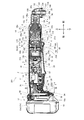
- FIG. 5 is a view corresponding to FIG. 1 of the angle impact driver 201 according to the second embodiment
- FIG. 6 is a view corresponding to FIG. 2 according to the second embodiment
- FIG. 7 is a view corresponding to FIG.
- the angle impact driver 201 of the second form is configured similarly to the first form except for the arrangement of the brushless motor, the light, the control circuit board, the fan, the sensor board, the intake port, the exhaust port, and the lead wire.
- members similar to those in the first embodiment are denoted by the same reference numerals, and description thereof will be omitted as appropriate.
- the brushless motor 216 of the second form is directed backward and forward from the first form. That is, the second insulating member 74 is disposed in front, and the first insulating member 72 is disposed behind.
- the sensor substrate 280 is fixed in front of the second insulating member 74.
- the sensor substrate 280 is configured in the same manner as the sensor substrate 80 except that the front and rear and the top and bottom are reversed. That is, the connection portions with the lead wires 40 and 41 and the power supply lead wires 52 are arranged at the lower back.
- Each rotation detecting element 81 is arranged at the lower part of the rear surface.
- a fan 68 is disposed after the first insulating member 72.
- the intake port is formed in a portion of the housing 2 outside the front portion of the brushless motor 16, and the exhaust port is formed in a portion of the housing 2 outside the rear side of the switch 14 (forward / reverse reversing switch 24). .
- the light 26 is disposed at the lower front side of the control circuit board 236 and is directly connected to the control circuit board 236 by terminals 242a and 242a.
- the control circuit board 236 is configured in the same manner as the control circuit board 36 except for the wiring related to the light 26.
- the switch 14 is disposed between the battery 10 and the brushless motor 216.
- a switch 14 is disposed between the control circuit board 236 and the brushless motor 216.
- a stator 58 is disposed between the sensor substrate 280 and the switch 14.
- the switch 14 is provided between the control circuit board 236 and the plurality of switching elements 44, 44. Further, the switch 14, the brushless motor 216, and the output shaft 20 are arranged on a straight line.
- the rotation state of the motor shaft 60 can be reliably detected with an efficient configuration, and it is more compact and easy to grip. It can be configured, and further maintenance work is reduced, so that an unusable period can be prevented.
- the switch 14 since the switch 14 is disposed between the battery 10 and the brushless motor 216, the power lead wires 38, 52,... Can be shortened, the wiring can be easily routed, and even if a load is applied, it is difficult to disconnect. be able to.
- the switch 14 is disposed between the control circuit board 236 and the brushless motor 216, the power supply lead wires 38, 52... And the lead wire 40 between the switch 14 and the control circuit board 236 and the brushless motor 216. , 41... Can be easily wired, and heat resistance can be further improved, so that the operation of the brushless motor 216 can be made more reliable.
- the brushless motor 216 having the rotor 56 including the motor shaft 60 and the stator 58, the motor shaft 60 fixed to the rotor 56, the fan 68 fixed to the motor shaft 60, and the brushless motor 216 are energized.
- the rotation of the brushless motor 216, the output shaft 20 having an angle with respect to the motor shaft 60, the housing 2 housing the brushless motor 216 and the switch 14, and the rotation of the rotor 56 are detected. Since the stator 58 is disposed between the sensor board 280 and the switch 14, the fan 68 can be installed on the opposite side of the sensor board 280 with the stator 58 interposed therebetween. It is possible to install an air intake on the front side of 58 and to install an air exhaust in a state separated from this air intake.
- Te hardly mixed exhaust and intake, or to not easily block the intake and exhaust by hand, it is possible to more smoothly flow the wind.
- the switch 14 the brushless motor 216, and the output shaft 20 are arranged on a straight line, the size can be reduced.
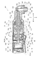
- FIG. 8 is a view corresponding to FIG. 1 of the angle impact driver 301 according to the third embodiment
- FIG. 9 is a view corresponding to FIG. 2 of the third embodiment
- FIG. 10 is a view corresponding to FIG.
- FIG. 5 is a diagram corresponding to FIG. 4 of the third embodiment.
- the angle impact driver 301 of the third embodiment is configured in the same manner as in the first embodiment, except for the configuration of the control circuit board and the sensor board, and the types of signals flowing in some lead wires.
- members similar to those in the first embodiment are denoted by the same reference numerals, and description thereof will be omitted as appropriate.
- the sensor board 380 of the third form includes rotation detection elements 81, 81,... On the front side and switching elements 44, 44,... (Three-phase bridge circuit unit 84) on the rear side, and a control circuit board 336. Does not include the switching elements 44, 44... (Three-phase bridge circuit unit 84) but includes a microcomputer 46 that controls them.
- the switching elements 44, 44,... Are arranged in a ring shape so as to be positioned at each vertex of the hexagon. Small holes 372, 372... And small slits 373, 373... Are provided on the periphery of the sensor substrate 380, and small protrusions projecting from the rear surface other than the recesses 78, 78. 374, 374...
- the sensor substrate 380 has small holes corresponding to the small holes 372 and the lower small slits 373. It is fixed with the projection 374 inserted.
- screw holes (not shown) are provided in portions corresponding to the left and right small slits 373 and 373 in the rear portion of the second insulating member 74, and the sensor substrate 380 is formed by inserting screws 376 into the screw holes.
- the second insulating member 74 is fixed to the rear side.
- coil connection portions 377, 377,... Corresponding to the coils 76, 76,...
- each lead wire 340 (six) wired instead of each lead wire 40 (three) is replaced with an output signal of the switching elements 44, 44,.
- Drive signals 89, 89,... For controlling on / off of the switching elements 44, 44,...
- the three-phase bridge circuit unit 84 (FIG. 11 collectively represents one white arrow) are transmitted.
- the power supply lead wire 52 and the lead wires 340 and 41 are connected on the upper rear surface of the sensor substrate 380.
- the upper rear surface (lead wire connecting portion 380a) of the sensor substrate 380 protrudes upward with respect to the lower disk-shaped portion.
- the sensor substrate 380 is fixed to the brushless motor 16. Further, a switch 14 is disposed between the battery 10 and the brushless motor 16. A switch 14 is disposed between the control circuit board 336 and the brushless motor 16. Further, a stator 58 is disposed between the fan 68 and the switch 14. In addition, the switch 14 is provided between the control circuit board 336 and the plurality of switching elements 44, 44. Further, the switch 14, the brushless motor 16 and the output shaft 20 are arranged on a straight line.
- the rotation state of the motor shaft 60 can be reliably detected with an efficient configuration, and is more compact and easy to grip. It can be configured, and further maintenance work is reduced, so that an unusable period can be prevented.
- the switch 14 since the switch 14 is disposed between the battery 10 and the brushless motor 16, the power supply leads 38, 52,... Can be shortened, the wiring can be easily routed, and even if a load is applied, it is difficult to disconnect. be able to.
- the switch 14 is disposed between the control circuit board 336 and the brushless motor 16, the power supply lead wires 38, 52... And the lead wire 340 between the switch 14 and the control circuit board 336 and the brushless motor 16. , 41... Can be easily wired, and the resistance to heat can be further improved to make the operation of the brushless motor 16 more reliable.
- the stator 58 is disposed between the fan 68 and the switch 14, the cooling efficiency of the brushless motor 16 becomes better, and the diameter of the housing 2 can be made relatively small.
- the switch 14 is provided between the control circuit board 336 and the switching elements 44, 44,..., The switching elements 44, 44,. It becomes less likely to be trapped, and the switching elements 44, 44,... And the control circuit board 436 can be easily cooled, and a more reliable operation can be realized.
- the switch 14 the brushless motor 16, and the output shaft 20 are arranged on a straight line, the size can be reduced.
- [Fourth form] 12 is a view corresponding to FIG. 1 of an angle impact driver 401 according to the fourth embodiment
- FIG. 13 is a view corresponding to FIG. 2 of the fourth embodiment
- FIG. 14 is a view corresponding to FIG.
- the angle impact driver 401 of the fourth embodiment is configured in the same manner as in the second embodiment, except for the configuration of the control circuit board and the sensor board, and the types of signals flowing in some lead wires.
- the same reference numerals are given to the same members as those in the second embodiment, and description thereof will be omitted as appropriate.
- the sensor board 480 of the fourth form includes the rotation detecting elements 81, 81,... On the rear side and the switching elements 44, 44,... (Three-phase bridge circuit unit 84) on the front side. It is configured in the same manner as the three forms of sensor substrate 380 and fixed in the same manner. However, the power supply lead wire 52 and the lead wires 340 and 41 are connected at the lower rear portion of the sensor substrate 480 (the lead wire connecting portion 380a is arranged at the lower portion).
- the sensor board 280 of the second form is fixed in the same manner as the sensor board 480 of the fourth form.
- the control circuit board 436 of the fourth form is configured in the same manner as the control circuit board 336 of the third form except that the connection with the light 26 is direct as in the second form.
- Drive signals 89, 89,... Are transmitted between the control circuit board 436 and the sensor board 480 on the lead wires 340 wired in place of the lead wires 40 (three). Further, in the angle impact driver 401, the brushless motor 216 is disposed in the same manner as in the second embodiment, and the pinion 69, the front bearing 62, the sensor board 480, the stator 58, the fan 68, and the rear bearing 64 are arranged in this order from the front. Are lined up.
- the sensor substrate 480 is fixed to the brushless motor 216.
- a switch 14 is disposed between the battery 10 and the brushless motor 216.
- a switch 14 is disposed between the control circuit board 436 and the brushless motor 216.
- a stator 58 is disposed between the sensor substrate 480 and the switch 14.
- a stator 58 is disposed between the sensor substrate 480 and the switch 14.
- the switch 14 is provided between the control circuit board 436 and the plurality of switching elements 44, 44. Further, the switch 14, the brushless motor 216, and the output shaft 20 are arranged on a straight line.
- the rotation state of the motor shaft 60 can be reliably detected with an efficient configuration, and is more compact and easy to grip. It can be configured, and further maintenance work is reduced, so that an unusable period can be prevented.
- the switch 14 since the switch 14 is disposed between the battery 10 and the brushless motor 216, the power lead wires 38, 52,... Can be shortened, the wiring can be easily routed, and even if a load is applied, it is difficult to disconnect. be able to.
- the switch 14 is disposed between the control circuit board 436 and the brushless motor 216, the power supply lead wires 38, 52,... And the lead wire 340 between the switch 14 and the control circuit board 436 and the brushless motor 216 are arranged. , 41... Can be easily wired, and heat resistance can be further improved, so that the operation of the brushless motor 216 can be made more reliable.
- the stator 58 is disposed between the sensor board 480 and the switch 14, the fan 68 can be placed on the opposite side of the sensor board 480 with the stator 58 interposed therebetween, making it difficult to mix intake and exhaust air, or The air flow can be made smoother by making it difficult for the air to be blocked by hand.
- the switch 14 is provided between the control circuit board 436 and the switching elements 44, 44,..., The switching elements 44, 44,. It is possible to further reduce the possibility of stagnation, and the switching elements 44, 44,... And the control circuit board 436 can be easily cooled, and more reliable operation can be realized.
- the switch 14 since the switch 14, the brushless motor 216, and the output shaft 20 are arranged on a straight line, the size can be reduced.
- the lead wire can be appropriately increased or decreased depending on the product to be implemented.
- the number of housing sections, the number of installed planetary gears, or the number of magnet poles of a brushless motor may be increased or decreased.
- the sensor substrate is fixed to the stator by a projection that enters the hole, by a screw and a screw hole, by a latch by a claw and its latching portion, or a combination thereof.
- the gap between the stator and the sensor substrate may be formed by providing a concave portion on the sensor substrate side, or by forming a concave portion on both sides, or by providing a convex portion at least on either side. It may be formed. Further, the present invention is applied to other rotary impact tools other than the angle impact driver, other impact tools, other angle tools, or other electric tools.
Landscapes
- Engineering & Computer Science (AREA)
- Power Engineering (AREA)
- Mechanical Engineering (AREA)
- Portable Power Tools In General (AREA)
- Brushless Motors (AREA)
Priority Applications (3)
| Application Number | Priority Date | Filing Date | Title |
|---|---|---|---|
| DE212014000099.8U DE212014000099U1 (de) | 2013-04-04 | 2014-02-05 | Winkelwerkzeug und elektrisches Werkzeug |
| US14/763,626 US20150364972A1 (en) | 2013-04-04 | 2014-02-05 | Angle tool and electric tool |
| CN201490000573.8U CN205184693U (zh) | 2013-04-04 | 2014-02-05 | 角工具以及电动工具 |
Applications Claiming Priority (2)
| Application Number | Priority Date | Filing Date | Title |
|---|---|---|---|
| JP2013-078810 | 2013-04-04 | ||
| JP2013078810A JP6018010B2 (ja) | 2013-04-04 | 2013-04-04 | アングル工具 |
Publications (1)
| Publication Number | Publication Date |
|---|---|
| WO2014162772A1 true WO2014162772A1 (ja) | 2014-10-09 |
Family
ID=51658076
Family Applications (1)
| Application Number | Title | Priority Date | Filing Date |
|---|---|---|---|
| PCT/JP2014/052678 Ceased WO2014162772A1 (ja) | 2013-04-04 | 2014-02-05 | アングル工具及び電動工具 |
Country Status (5)
| Country | Link |
|---|---|
| US (1) | US20150364972A1 (enExample) |
| JP (1) | JP6018010B2 (enExample) |
| CN (1) | CN205184693U (enExample) |
| DE (1) | DE212014000099U1 (enExample) |
| WO (1) | WO2014162772A1 (enExample) |
Cited By (1)
| Publication number | Priority date | Publication date | Assignee | Title |
|---|---|---|---|---|
| US20150340921A1 (en) * | 2014-05-26 | 2015-11-26 | Makita Corporation | Electric power tool |
Families Citing this family (18)
| Publication number | Priority date | Publication date | Assignee | Title |
|---|---|---|---|---|
| WO2016031719A1 (ja) * | 2014-08-29 | 2016-03-03 | 日立工機株式会社 | 電動作業機 |
| US10404136B2 (en) * | 2015-10-14 | 2019-09-03 | Black & Decker Inc. | Power tool with separate motor case compartment |
| WO2017082360A1 (ja) * | 2015-11-11 | 2017-05-18 | 株式会社マキタ | 結束機 |
| JP6697895B2 (ja) * | 2016-02-19 | 2020-05-27 | 株式会社マキタ | 作業工具 |
| JP6758853B2 (ja) * | 2016-02-22 | 2020-09-23 | 株式会社マキタ | アングル工具 |
| US11192223B2 (en) | 2017-03-07 | 2021-12-07 | Makita Corporation | Tool holding apparatus and power tool, and impact tool |
| JP7020789B2 (ja) * | 2017-03-24 | 2022-02-16 | 株式会社マキタ | アングルドリル |
| CN110446587B (zh) | 2017-03-31 | 2023-06-13 | 工机控股株式会社 | 电动工具 |
| WO2018198671A1 (ja) * | 2017-04-27 | 2018-11-01 | 工機ホールディングス株式会社 | 電動工具 |
| WO2019020307A1 (de) * | 2017-07-24 | 2019-01-31 | Festool Gmbh | Elektrowerkzeug und verfahren |
| JP7220362B2 (ja) * | 2017-09-25 | 2023-02-10 | パナソニックIpマネジメント株式会社 | 電動工具 |
| JP6987667B2 (ja) | 2018-02-23 | 2022-01-05 | 株式会社マキタ | インパクト工具 |
| US12301081B2 (en) * | 2018-12-26 | 2025-05-13 | Makita Corporation | Electric work machine |
| CN112238411B (zh) * | 2019-07-19 | 2024-02-20 | 株式会社牧田 | 电动工具及旋转工具 |
| GB2583796A (en) * | 2019-11-15 | 2020-11-11 | Black & Decker Inc | Motor terminals facing gear case in a power tool |
| JP7462273B2 (ja) * | 2020-07-31 | 2024-04-05 | パナソニックIpマネジメント株式会社 | インパクト回転工具 |
| TWI750884B (zh) * | 2020-11-04 | 2021-12-21 | 朝程工業股份有限公司 | 電動工具 |
| JP2024143630A (ja) | 2023-03-30 | 2024-10-11 | 株式会社マキタ | アングルインパクト工具 |
Citations (5)
| Publication number | Priority date | Publication date | Assignee | Title |
|---|---|---|---|---|
| US20010031179A1 (en) * | 1998-04-23 | 2001-10-18 | Potter Christine H. | Two speed right angle drill |
| JP2007295773A (ja) * | 2006-04-27 | 2007-11-08 | Makita Corp | Dcブラシレスモータ |
| JP2007330065A (ja) * | 2006-06-09 | 2007-12-20 | Makita Corp | 電動工具のdcブラシレスモータ |
| JP2011062770A (ja) * | 2009-09-16 | 2011-03-31 | Hitachi Koki Co Ltd | 電動工具 |
| JP2013022681A (ja) * | 2011-07-21 | 2013-02-04 | Hitachi Koki Co Ltd | 電動工具 |
Family Cites Families (10)
| Publication number | Priority date | Publication date | Assignee | Title |
|---|---|---|---|---|
| JP2007014147A (ja) * | 2005-06-30 | 2007-01-18 | Fujitsu General Ltd | 電動機 |
| US7786626B2 (en) * | 2006-11-03 | 2010-08-31 | Pacific Bioscience Laboratories, Inc. | Oscillating motor for a personal care appliance |
| JP2008173716A (ja) * | 2007-01-18 | 2008-07-31 | Max Co Ltd | ブラシレスモータを備えた電動工具 |
| JP5088614B2 (ja) * | 2007-09-28 | 2012-12-05 | 日立工機株式会社 | 電動工具 |
| JP5143522B2 (ja) | 2007-10-11 | 2013-02-13 | 株式会社マキタ | 電動ドリル |
| JP5589255B2 (ja) * | 2008-02-26 | 2014-09-17 | 日立工機株式会社 | 携帯用電動工具 |
| JP5182562B2 (ja) * | 2008-02-29 | 2013-04-17 | 日立工機株式会社 | 電動工具 |
| WO2009145206A2 (en) * | 2008-05-29 | 2009-12-03 | Hitachi Koki Co., Ltd. | Electric power tool |
| JP5472683B2 (ja) * | 2009-05-11 | 2014-04-16 | 日立工機株式会社 | 電動工具 |
| JP6270510B2 (ja) * | 2014-01-30 | 2018-01-31 | 東京パーツ工業株式会社 | Dcブラシレスモータ |
-
2013
- 2013-04-04 JP JP2013078810A patent/JP6018010B2/ja active Active
-
2014
- 2014-02-05 CN CN201490000573.8U patent/CN205184693U/zh not_active Expired - Lifetime
- 2014-02-05 WO PCT/JP2014/052678 patent/WO2014162772A1/ja not_active Ceased
- 2014-02-05 DE DE212014000099.8U patent/DE212014000099U1/de not_active Expired - Lifetime
- 2014-02-05 US US14/763,626 patent/US20150364972A1/en not_active Abandoned
Patent Citations (5)
| Publication number | Priority date | Publication date | Assignee | Title |
|---|---|---|---|---|
| US20010031179A1 (en) * | 1998-04-23 | 2001-10-18 | Potter Christine H. | Two speed right angle drill |
| JP2007295773A (ja) * | 2006-04-27 | 2007-11-08 | Makita Corp | Dcブラシレスモータ |
| JP2007330065A (ja) * | 2006-06-09 | 2007-12-20 | Makita Corp | 電動工具のdcブラシレスモータ |
| JP2011062770A (ja) * | 2009-09-16 | 2011-03-31 | Hitachi Koki Co Ltd | 電動工具 |
| JP2013022681A (ja) * | 2011-07-21 | 2013-02-04 | Hitachi Koki Co Ltd | 電動工具 |
Cited By (1)
| Publication number | Priority date | Publication date | Assignee | Title |
|---|---|---|---|---|
| US20150340921A1 (en) * | 2014-05-26 | 2015-11-26 | Makita Corporation | Electric power tool |
Also Published As
| Publication number | Publication date |
|---|---|
| US20150364972A1 (en) | 2015-12-17 |
| JP6018010B2 (ja) | 2016-11-02 |
| CN205184693U (zh) | 2016-04-27 |
| JP2014200884A (ja) | 2014-10-27 |
| DE212014000099U1 (de) | 2015-11-12 |
Similar Documents
| Publication | Publication Date | Title |
|---|---|---|
| JP6018010B2 (ja) | アングル工具 | |
| US11090784B2 (en) | Screw-tightening power tool | |
| JP2016215373A (ja) | アングル工具 | |
| JP4981345B2 (ja) | 電動工具 | |
| CN102785232B (zh) | 电动工具及电动工具用的通信插头 | |
| CN111590506B (zh) | 电动工具 | |
| JP5354363B2 (ja) | 電動工具 | |
| CN106998110B (zh) | 电动工具 | |
| JP4974054B2 (ja) | 電動工具 | |
| JP2014113664A (ja) | 電動工具 | |
| WO2010035563A1 (ja) | 電動工具 | |
| JP5332163B2 (ja) | 電動工具 | |
| JP2013000863A (ja) | 電動工具 | |
| JP2016153157A (ja) | 電動工具 | |
| JP2014168840A (ja) | 電動工具 | |
| JP2017087330A (ja) | 電動工具 | |
| JP7129871B2 (ja) | インパクト工具及び電動工具 | |
| JP6626944B2 (ja) | 電動工具 | |
| JP6417250B2 (ja) | 電動工具 | |
| JP4947490B2 (ja) | 電動工具 | |
| JP6138526B2 (ja) | スクリュードライバ | |
| JP2017071055A (ja) | ネジ締め電動工具 | |
| JP2020188631A (ja) | 電動作業機 | |
| JP7536060B2 (ja) | インパクト工具 | |
| JP2018111206A (ja) | ネジ締め電動工具 |
Legal Events
| Date | Code | Title | Description |
|---|---|---|---|
| WWE | Wipo information: entry into national phase |
Ref document number: 201490000573.8 Country of ref document: CN |
|
| 121 | Ep: the epo has been informed by wipo that ep was designated in this application |
Ref document number: 14780010 Country of ref document: EP Kind code of ref document: A1 |
|
| WWE | Wipo information: entry into national phase |
Ref document number: 14763626 Country of ref document: US |
|
| WWE | Wipo information: entry into national phase |
Ref document number: 2120140000998 Country of ref document: DE Ref document number: 212014000099 Country of ref document: DE |
|
| 122 | Ep: pct application non-entry in european phase |
Ref document number: 14780010 Country of ref document: EP Kind code of ref document: A1 |