WO2014162772A1 - Angle tool and electric tool - Google Patents
Angle tool and electric tool Download PDFInfo
- Publication number
- WO2014162772A1 WO2014162772A1 PCT/JP2014/052678 JP2014052678W WO2014162772A1 WO 2014162772 A1 WO2014162772 A1 WO 2014162772A1 JP 2014052678 W JP2014052678 W JP 2014052678W WO 2014162772 A1 WO2014162772 A1 WO 2014162772A1
- Authority
- WO
- WIPO (PCT)
- Prior art keywords
- brushless motor
- switch
- motor
- shaft
- housing
- Prior art date
Links
- 239000000758 substrate Substances 0.000 claims abstract description 49
- WABPQHHGFIMREM-UHFFFAOYSA-N lead(0) Chemical compound [Pb] WABPQHHGFIMREM-UHFFFAOYSA-N 0.000 description 14
- 238000001514 detection method Methods 0.000 description 13
- 238000012423 maintenance Methods 0.000 description 12
- 230000007246 mechanism Effects 0.000 description 6
- 210000000078 claw Anatomy 0.000 description 5
- 238000001816 cooling Methods 0.000 description 4
- 230000003247 decreasing effect Effects 0.000 description 4
- 230000005540 biological transmission Effects 0.000 description 3
- 238000010586 diagram Methods 0.000 description 3
- 238000000034 method Methods 0.000 description 3
- HBBGRARXTFLTSG-UHFFFAOYSA-N Lithium ion Chemical compound [Li+] HBBGRARXTFLTSG-UHFFFAOYSA-N 0.000 description 2
- 239000003990 capacitor Substances 0.000 description 2
- 238000009499 grossing Methods 0.000 description 2
- 229910001416 lithium ion Inorganic materials 0.000 description 2
- 230000004048 modification Effects 0.000 description 2
- 238000012986 modification Methods 0.000 description 2
- 229910000679 solder Inorganic materials 0.000 description 2
- 239000000853 adhesive Substances 0.000 description 1
- 230000001070 adhesive effect Effects 0.000 description 1
- 230000003139 buffering effect Effects 0.000 description 1
- 230000008859 change Effects 0.000 description 1
- 238000007599 discharging Methods 0.000 description 1
- 239000000428 dust Substances 0.000 description 1
- 230000005611 electricity Effects 0.000 description 1
- 238000005516 engineering process Methods 0.000 description 1
- 230000005669 field effect Effects 0.000 description 1
- 230000001771 impaired effect Effects 0.000 description 1
- 230000006872 improvement Effects 0.000 description 1
- 230000007257 malfunction Effects 0.000 description 1
- 239000000463 material Substances 0.000 description 1
- 229910052751 metal Inorganic materials 0.000 description 1
- 239000002184 metal Substances 0.000 description 1
- 230000002093 peripheral effect Effects 0.000 description 1
- 238000005476 soldering Methods 0.000 description 1
- 125000006850 spacer group Chemical group 0.000 description 1
- 230000002194 synthesizing effect Effects 0.000 description 1
- 229920002725 thermoplastic elastomer Polymers 0.000 description 1
Images


Classifications
-
- B—PERFORMING OPERATIONS; TRANSPORTING
- B25—HAND TOOLS; PORTABLE POWER-DRIVEN TOOLS; MANIPULATORS
- B25F—COMBINATION OR MULTI-PURPOSE TOOLS NOT OTHERWISE PROVIDED FOR; DETAILS OR COMPONENTS OF PORTABLE POWER-DRIVEN TOOLS NOT PARTICULARLY RELATED TO THE OPERATIONS PERFORMED AND NOT OTHERWISE PROVIDED FOR
- B25F5/00—Details or components of portable power-driven tools not particularly related to the operations performed and not otherwise provided for
-
- H—ELECTRICITY
- H02—GENERATION; CONVERSION OR DISTRIBUTION OF ELECTRIC POWER
- H02K—DYNAMO-ELECTRIC MACHINES
- H02K7/00—Arrangements for handling mechanical energy structurally associated with dynamo-electric machines, e.g. structural association with mechanical driving motors or auxiliary dynamo-electric machines
- H02K7/14—Structural association with mechanical loads, e.g. with hand-held machine tools or fans
- H02K7/145—Hand-held machine tool
-
- H—ELECTRICITY
- H02—GENERATION; CONVERSION OR DISTRIBUTION OF ELECTRIC POWER
- H02K—DYNAMO-ELECTRIC MACHINES
- H02K5/00—Casings; Enclosures; Supports
- H02K5/04—Casings or enclosures characterised by the shape, form or construction thereof
Definitions
- the present invention relates to an angle tool having an output shaft arranged at an angle with respect to a motor shaft, and an electric tool having an output shaft.
- an electric drill in which a bit rotates around an axis that intersects the rotation axis of a motor.
- the motor of this electric drill has a commutator on the rotating shaft side that can come into contact with the brush of the stator in order to rotate the rotor by switching the direction of the current flowing in the coil of the rotor.
- the brush gradually wears due to contact with the rotating commutator, and eventually the current is not sufficiently passed, so that the power drill is provided with a brush replacement protrusion or lid.
- the conventional electric drill as described above has a commutator and a brush to rotate the rotating shaft of the motor, it is necessary to provide a protrusion and a lid for replacing the brush, and accordingly, it becomes less compact.
- the motor does not rotate until the brush is replaced with a new brush, and the bit cannot be rotated, and the electric drill cannot be used.
- the brush needs to be replaced, which takes time. Therefore, the main object of the present invention is to provide an angle tool that is more compact and easy to grip, requires less maintenance, and prevents the occurrence of an unusable period.
- a first aspect of the present invention is directed to a brushless motor having a motor shaft, a switch for energizing the brushless motor, and rotation of the brushless motor transmitted to the motor shaft. And an output shaft having an angle, a housing for housing the brushless motor and the switch, and a sensor substrate for detecting rotation of the motor shaft, and the sensor substrate on the brushless motor. It is characterized by fixing.
- a brushless motor having a motor shaft, a switch for energizing the brushless motor, an output shaft that is transmitted with rotation of the brushless motor and has an angle with respect to the motor shaft.
- a housing for housing the brushless motor and the switch, and a battery fixed to the housing, and the switch is disposed between the battery and the brushless motor. It is.
- a brushless motor having a motor shaft, a switch for energizing the brushless motor, an output shaft which is transmitted with rotation of the brushless motor and has an angle with respect to the motor shaft.
- a brushless motor having a rotor including a motor shaft and a stator, a motor shaft fixed to the rotor, a fan fixed to the motor shaft, and the brushless motor are energized.
- a switch for transmitting rotation of the brushless motor, an output shaft having an angle with respect to the motor shaft, a housing for housing the brushless motor and the switch, and a sensor for detecting rotation of the rotor And the stator is arranged between the sensor substrate and the switch.
- the invention according to claim 5 is a brushless motor having a rotor including a motor shaft and a stator, a fan fixed to the motor shaft, a switch for energizing the brushless motor, and rotation of the brushless motor.
- the invention according to claim 6 is a brushless motor having a stator and a rotor, a motor shaft fixed to the rotor, a fan fixed to the motor shaft, a switch for energizing the brushless motor, An output shaft that is transmitted with the rotation of the brushless motor and has an angle with respect to the motor shaft, a housing that houses the brushless motor and the switch, a control circuit board that is housed in the housing, and the stator And a plurality of switching elements electrically connected to each other, and the switch is provided between the control circuit board and the plurality of switching elements.
- the invention according to claim 7 is a brushless motor having a stator and a rotor, a motor shaft fixed to the rotor, a fan fixed to the motor shaft, a switch for energizing the brushless motor, It has an output shaft to which the rotation of the brushless motor is transmitted, and a housing that houses the brushless motor and the switch, and the switch, the brushless motor, and the output shaft are arranged in a straight line. It is what.
- the rotation state of the motor shaft can be reliably detected with an efficient configuration, and the sensor can be more compact. It can be configured so that it can be easily gripped, and the maintenance work is reduced, thereby preventing the occurrence of an unusable period.
- the switch since the switch is arranged between the battery and the brushless motor, it is easy to route the wiring, and even if a load is applied, it can be made difficult to be disconnected, and more compact. It can be configured to be easily gripped, and the maintenance work is reduced, so that an unusable period can be prevented.
- the switch since the switch is arranged between the control circuit board and the brushless motor, the wiring is easy to perform and the resistance to heat is further improved, so that the operation of the brushless motor 216 is further improved. It can be made reliable, can be configured to be more compact and easy to grip, and further requires less maintenance, thereby preventing the occurrence of an inoperable period.
- the stator of the brushless motor since the stator of the brushless motor is disposed between the sensor board and the switch, the flow of wind can be made smoother, and it can be configured more compactly and easily gripped. Furthermore, the maintenance time is small and the occurrence of an unusable period is prevented.
- the brushless motor stator is arranged between the fan and the switch, the cooling efficiency of the brushless motor becomes better, and it can be configured more compactly and easily gripped. Occurrence of unusable periods is prevented with less maintenance effort.
- the switch since the switch is disposed between the control circuit board and the switching element, the switching element and the control circuit board can be easily cooled, thereby realizing more reliable operation. In addition, it can be configured to be more compact and easy to grip, and further, the maintenance work is reduced and the occurrence of an unusable period is prevented.
- the switch since the switch, the brushless motor, and the output shaft are arranged in a straight line, the switch can be configured more compactly and easily gripped, and further, the maintenance work is less and the inoperable period is generated. Is prevented.
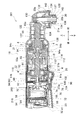
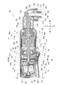
- FIG. 2 is an enlarged view of the front part of FIG. 1.
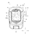
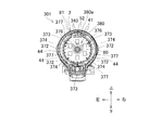
- FIG. 2 is a cross-sectional view taken along the line AA in FIG.
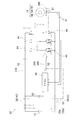
- FIG. 4 is a circuit diagram including a control circuit board of FIG. 3.
- FIG. 3 is a view corresponding to FIG. 1 according to a second embodiment of the present invention.
- FIG. 6 is a front enlarged view of FIG. 5.
- FIG. 6 is a sectional view taken along line BB in FIG. 5.
- FIG. 6 is a view corresponding to FIG. 1 according to a third embodiment of the present invention.
- FIG. 9 is an enlarged view of the front part of FIG. 8.
- FIG. 10 is a cross-sectional view taken along the line CC of FIG. 8 (FIG. 9).
- FIG. 5 is a diagram corresponding to FIG. 4 of the third embodiment. It is FIG. 1 equivalent view which concerns on the 4th form of this invention. It is a front enlarged view of FIG. FIG. 13 is a DD cross-sectional view of FIG. 12 (FIG. 13).
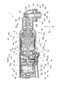
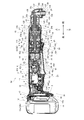
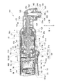
- FIG. 1 is a longitudinal center sectional view of an angle impact driver 1 which is an example of an angle type electric tool according to the first embodiment
- FIG. 2 is an enlarged front view of FIG. 1, and FIG. It is A sectional drawing.
- the angle type means that the motor shaft and the output shaft intersect at an angle of approximately 90 °.
- the right side in FIG. 1 is the front in the angle impact driver 1.
- the angle impact driver 1 has a housing 2 that forms the outline thereof.
- the housing 2 is formed so that it can be divided in half on the left and right sides, and the left and right portions are coupled to each other by a plurality of screws 3, 3... And corresponding cylindrical screw holes 4, 4.
- the housing 2 is formed in a cylindrical shape whose center axis is the front-rear direction.
- a battery mounting portion 12 to which the battery 10 can be attached is formed at the rear end portion of the housing 2.
- a switch 14 is accommodated in the rear portion of the housing 2 and in front of the battery mounting portion 12.
- a brushless motor 16 is accommodated in the center of the housing 2 and in front of the switch 14.
- a portion of the housing 2 from the battery mounting portion 12 to the outer front side of the brushless motor 16 is a main body housing 17.
- the main body of the angle impact driver 1 is formed by the main body housing 17 or a member accommodated therein.
- a driving force transmission mechanism 18 and an output shaft 20 are accommodated in the front portion of the housing 2 and in front of the brushless motor 16.
- a portion of the housing 2 that covers the driving force transmission mechanism 18 and the output shaft 20 is a metal hammer case 21 and a gear case 22 disposed in the front portion of the main body housing 12.
- the hammer case 21 is fixed to the gear case 22 by a fixing screw 21b.
- a hammer 93 and an anvil 94 described later are double-covered by the hammer case 21 and the gear case 22.
- a trigger-type switch lever 23 that can be pushed by a user with a finger or the like while being partially exposed from the housing 2 is provided below the switch 14.
- the forward / reverse reversing switch 24 for sequentially switching the rotation direction of the brushless motor 16 is accommodated in a state where it is partially exposed from the left and right side surfaces of the housing 2.
- the switch lever 23 is configured to be rotatable about the upper end 23a.
- the outer part of the rear part or the center part of the housing 2 (the outer part before the forward / reverse reversing switch 24 and after the outer side of the brushless motor 16) is formed as a grip to be gripped by the user.
- An anti-slip member (thermoplastic elastomer) is disposed on the grip.
- a light (LED) 26 that illuminates the front (near the lower end of the output shaft 20) is provided below the brushless motor 16.
- a hook 28 is attached to the rear side surface of the housing 2 with a screw 27 (FIG. 3).
- the battery 10 is a substantially rectangular parallelepiped rechargeable battery, and has lithium ion battery cells inside.
- the battery 10 has a detachable button 30 that can be pushed forward in the lower rear part (FIG. 3).
- the removal button 30 is urged rearward by an elastic body (spring), and is normally positioned along the other part of the battery 10.
- the battery 10 has a claw 32 that can protrude and retract with respect to the periphery of the battery 10 at the front lower portion. When the removal button 30 is in the normal position, the claw 32 is in a protruding state, and when the removal button 30 is pushed forward against the urging force, the claw 32 is in a buried state.
- the battery 10 has a terminal 33a on the front surface and two rails 10a and 10a extending vertically.
- the battery mounting portion 12 has a planar portion that extends in the vertical and horizontal directions, and an engaging recess 34 that is recessed forward with respect to the periphery is formed on the lower side of the planar portion.
- the battery mounting portion 12 has a rail engaging portion that engages with a corresponding rail 10a of the battery 10 on the rear surface, and also has a terminal 33b.
- a control circuit board 36 is disposed on the inner side (front side) of the battery mounting portion 12.
- Power supply leads 38 are provided between the control circuit board 36 and the switch 14 in front of the control circuit board 36.
- rotation control lead wires 40, 40... And a rotation detection signal lead wire 41 are provided between the control circuit board 36 and the light 26 in front of the control circuit board 36.
- Connectors 42c and 42d that can be coupled to each other are interposed between the lead wires 42a and 42b.
- the connectors 42c and 42d are attached in a coupled state in the rib 42e of the housing 2.
- the central portion of the write lead wire 42b is disposed above or in front of the outside of the motor housing 54 described later.
- power supply lead wires 43 and 43 are provided between the control circuit board 36 and the terminal 33 b of the battery mounting portion 12. Electricity at the terminal 33b of the battery mounting portion 12 is communicated to the switch 14 via the power supply lead wires 43 and 43, the control circuit board 36, and the power supply lead wires 38 and 38.
- a plurality (six) of switching elements 44, 44,... And a microcomputer 46 are mounted on the control circuit board 36.
- the switching elements 44, 44,... Are arranged so as to be divided into left and right and arranged in groups of three each. Three switching elements 44, 44... Are arranged on the left and right sides of the microcomputer 46.
- the switch 14 switches the energization state for the brushless motor 16 and is for energizing the brushless motor 16.
- the switch 14 has a switch body 50 and a plunger 51 that protrudes downward from the lower surface thereof. When the plunger 51 is pushed upward, the switch 14 is turned on. When the plunger 51 is not pushed and is in a normal position, the switch 14 is turned off. The rear portion of the switch lever 23 is in contact with the lower side of the plunger 51. Power supply leads 52 and 52 are provided between the switch 14 and a sensor board 80 (described later) fixed to the brushless motor 16 in front of the switch 14.
- the brushless motor 16 has a rotor 56 that is a rotor and a stator 58 that is a stator, and is accommodated inside the motor housing 54.
- the rotor 56 includes a motor shaft 60 that is a rotation shaft of the brushless motor 16, a front bearing 62 that supports the front portion of the motor shaft 60, a rear bearing 64 that supports the rear end portion of the motor shaft 60, and a motor shaft.
- 60 includes a rotor core (rotor core) and a magnet 66 provided integrally with the motor shaft 60 in the central portion of the motor 60.
- a fan 68 for discharging dust, heat and the like is integrally provided with the motor shaft 60 on the rear side of the front bearing 62.
- a pinion 69 is fixed to the front end portion of the motor shaft 60.
- the front bearing 62 is held at the rear center of the gear case 22, and the rear bearing 64 is held at the inner center of the rear end of the motor housing 54.
- the stator 58 includes a cylindrical stator core 70 whose axial direction is the front-rear direction, a disk-shaped first insulating member 72 disposed on the front side of the stator core (stator core) 70, and the rear side or stator core of the stator core 70.
- the rear surface of the second insulating member 74 is provided with a plurality of concave portions 78, 78,.
- a disc-shaped sensor substrate 80 is installed on the rear side of the second insulating member 74.
- the sensor substrate 80 is disposed so that the rear surface of the second insulating member 74 excluding the concave portions 78 and the corresponding portion of the substantially flat front surface of the sensor substrate 80 are in contact with each other.
- a gap is formed between 80.
- the upper end portion of the sensor substrate 80 protrudes upward from a hole formed in the rear upper portion of the motor housing 54 and is a portion to which the lead wires 40 and 41 and the power supply lead wires 52 are connected. Further, a hole through which the motor shaft 60 is passed is formed in the center portion of the sensor substrate 80.
- An air inlet (not shown) is formed in the body housing 17 outside the switch 14, and the outside air introduced from the air inlet into the housing 2 by the fan 68 is between the second insulating member 74 and the sensor substrate 80. It is possible to flow into the brushless motor 16 through the gap.
- An exhaust port (not shown) is formed in the main body housing 17 outside the fan 68.
- the sensor substrate 80 has a plurality (three in this case) of rotation detection elements 81, 81... (See FIG. 4) as rotation detection sensors.
- the rotation detection elements 81, 81,... Are arranged at equal intervals on the upper front surface of the sensor substrate 80.
- FIG. 4 shows a drive circuit 82 of the angle impact driver 1 including each switching element 44 and each rotation detection element 81.
- the drive circuit 82 includes a power supply circuit unit 83, a three-phase bridge circuit unit 84 including switching elements 44, 44,..., And a microcomputer 46 that controls the switching elements 44, 44,.
- the power supply circuit portion 83 is a portion that is mainly disposed on the control circuit board 36 and that suppresses voltage fluctuations in the power supplied from the battery 10 via the terminals 33a and 33b. , And a power supply smoothing capacitor 85 connected in parallel to the power supply leads 38, 43,.
- the three-phase bridge circuit portion 84 is a portion disposed on the control circuit board 36 and is connected to the power supply leads 38, 43... In parallel with the power supply smoothing capacitor 85, and the pair of switching elements 44. , 44 have three output lines extending from each of them. Each output line is connected to a corresponding coil 76 in the stator 58 of the brushless motor 16 via the lead wire 40 or the sensor substrate 80.
- An example of each switching element 44 is a field effect transistor (FET).
- the microcomputer 46 arranged on the control circuit board 36 receives the rotation detection signals transmitted from the respective rotation detection elements 81 arranged on the sensor board 80 by means of the lead wires 41, 41,. 81, 81...
- Each rotation detection element 81 detects the position of the magnetic pole of the rotor 56 and transmits it as a rotation detection signal.
- Each lead 41 is output from the sensor board 80 to the control circuit board 36. It is wiring.
- the microcomputer 46 acquires the rotation state (rotation angle from the reference position) of the rotor 56 by grasping and synthesizing the rotation detection signals indicating the position of the magnetic pole of the rotor 56 transmitted from each rotation detection element 81. It is possible.
- the microcomputer 46 controls on / off of the switching elements 44, 44,... In the three-phase bridge circuit unit 84 according to the acquired rotation state of the rotor 56 (according to the state of each received rotation detection signal).
- Drive signals 89, 89,... (Collectively represented by one white arrow in FIG. 4) are output to the corresponding switching elements 44.
- the control circuit board 36 includes at least one of the microcomputer 46 and the switching elements 44, 44... (Three-phase bridge circuit section 84)
- the control circuit board 36 is a board that controls the brushless motor 16.
- Various elements and lead wires on the sensor substrate 80 are mounted in a state in which the amount of protrusion from the surface (the rear surface of the sensor substrate 80) is suppressed by a reflow method or the like (surface mount, SMT: Surface Mount Technology).
- a reflow method solder printing according to a predetermined pattern is applied to the sensor substrate 80 (or adhesive is applied to a component mounting position by a dispenser), various elements and lead wires are placed by a chip mounter, and the reflow furnace is used. This is a method in which the solder is melted by applying heat to fix various elements and lead wires, and it is not necessary to open through holes for mounting elements and the like in the sensor substrate 80. Eliminates the need for soldering on the opposite side through the legs.
- the driving force transmission mechanism 18 includes, in order from the rear side, a planetary gear mechanism 90, a spindle 91, a coiled spring 92 that is an elastic body, a hammer 93, an anvil 94, and a shaft 95. It is stored coaxially.
- the planetary gear mechanism 90 includes an internal gear 100 having internal teeth, a plurality of planetary gears 102, 102... Having external teeth meshing with the internal gear 100, and pins 104 that are axes of the planetary gears 102. Including.
- the internal gear 100 is non-rotatably attached inside the gear case 22.
- Each planetary gear 102 meshes with a pinion 69 of the motor shaft 60 of the brushless motor 16 disposed inside the rear portion of the gear case 22.
- the spindle 91 is an axially long member having a disk-shaped part 91a at the rear part.
- the disc-shaped portion 91a protrudes outward (up, down, left and right) with respect to the other part of the spindle 91, and has a larger diameter than the other part.
- the rear part of the disk-shaped part 91 a is in the front part of the internal gear 100.
- a spindle bearing 110 that receives the spindle 91 is installed inside the screw hole portions 4 and 4 disposed in the gear case 24. The spindle bearing 110 is held in the middle of the gear case 22 and in front of the planetary gear mechanism 90.
- a plurality of pin holes (as many as the number of pins 104) corresponding to the front end portions of the pins 104 of the planetary gear 102 are provided on the rear surface of the disk-shaped portion 91a of the spindle 91. And each pin 104 is provided in the rear side of the disk-shaped part 91a in the state which put the front-end part in the pin hole. Each planetary gear 102 is provided around the pin 104 so as to be rotatable around the corresponding pin 104. Further, a spindle hole 91b, which is a hole from the rear surface to the front side of the disk-shaped portion 91a of the spindle 91, is provided. Inside the spindle hole 91b, the tip of the motor shaft 60 of the brushless motor 16 and the pinion 69 (planetary gear). The portion not engaged with 102 enters with a gap from the peripheral surface of the spindle hole 91b.
- the hammer 93 has a recess 93a that is recessed in a cylindrical shape from the rear surface to the front, and the front portion of the spring 92 is contained in the recess 93a. Between the bottom (front end) of the recess 93a and the front end of the spring 92, a washer 112 that contacts the front end surface of the spring 92 and a plurality of small balls 114, 114,. Has been. On the other hand, the rear end portion of the spring 92 is in contact with the washer 115, and the washer 115 is in contact with the spindle bearing 110. Note that balls 116 are disposed between the hammer 93 and the front portion of the spindle 91 to guide the hammer 93 mainly in the front-rear direction when hit.
- the anvil 94 on the front side of the hammer 93 has extended portions 94a and 94a extending in the radial direction at the rear end.
- An anvil bearing 120 is provided on the front side of the extending portions 94a and 94a to support the anvil 94 so as to be rotatable around the axis and not to be displaced in the axial direction.
- the anvil bearing 120 is held in front of the hammer 93 at the front portion of the gear case 22.
- a rear hole 94b which is a hole from the rear surface to the front, is formed in the center of the rear part of the anvil 94, and the front end of the spindle 91 is inserted into the rear hole 94b in a state in which the rotational impact force can be transmitted.
- the front part of the anvil 94 is provided with the front hole 94c which is a hole from the front to the rear which receives the rear part of the shaft 95 so that rotational force can be transmitted.
- the front hole 94c of the anvil 94 and the rear part of the shaft 95 are linked by a spline structure.
- the shaft 95 is a shaft-like member extending in the front-rear direction, and has a bevel tooth portion 95a at the front portion thereof.
- Shaft bearings 122 and 122 are arranged around the portion of the shaft 95 other than the bevel tooth portion 95a, and the shaft 95 is supported so as to be rotatable around its own axis.
- Each shaft bearing 122 is attached to the hammer case 21.
- a cylindrical spacer 124 is provided between the shaft bearings 122 and 122.
- the output shaft 20 is a shaft-like member extending vertically, and has a bevel tooth portion 20a at the center thereof.
- the bevel tooth portion 20 a meshes with the bevel tooth portion 95 a of the shaft 95.
- An upper output bearing 130 is provided around the upper end portion of the output shaft 20.
- a lower output bearing 132 is provided below the bevel tooth portion 20a of the output shaft 20.
- the output shaft 20 is supported by an upper output bearing 130 and a lower output bearing 132 so as to be rotatable about its own axis.
- a chuck portion 20b including a hole extending upward from the lower surface and capable of being mounted with a bit (not shown) is formed at the distal end portion (lower end portion) of the output shaft 20.
- Chuck balls 134 and 134 corresponding to the small concave portions of the bit are provided at the front and rear at the center of the chuck portion 20b.
- the outside of the chuck portion 20b is covered with a cylindrical sleeve 136, and a gap opened downward is formed between the lower outer surface of the chuck portion 20b and the lower inner surface of the sleeve 136, and a spring is formed in the gap. 137 and a washer 138 that contacts the lower surface thereof.
- the washer 138 is locked by a retaining ring 140 embedded in the outer surface of the tip end portion of the chuck portion 20c in a state of being in contact with the inner surface of the lower surface.
- the hammer case 21 has a downward opening 21a outside the sleeve 136, and an elastic bumper 142 covering the opening 21a is disposed outside or below the opening 21a. Yes.
- the hammer case 21 or a member in the front portion thereof (a member in front of the gear case 22, from the shaft 95 to the output shaft 20) can be made into an adapter (modulation), and the module has a rear portion of the hammer case 21 outside the gear case 22. Can be assembled by placing the rear portion of the shaft 95 into the front hole 94c of the anvil 94.
- the spindle 91 rotates the anvil 94 and the shaft 95, and guides the hammer 93 to swing back and forth (hit) when a torque exceeding a predetermined threshold is applied to the anvil 94.
- the buffering action by the spring 92 acts on the hammer 93 (or the spindle 91).
- the shaft 95 rotates (hits) the output shaft 20 having a 90 ° angle with the motor shaft 60 via the bevel teeth 95a and 20a, and rotates (hits) the bit mounted on the chuck portion 20b. .
- the angle impact driver 1 described above is transmitted to the brushless motor 16 having the motor shaft 60, the switch 14 for energizing the brushless motor 16, and the rotation of the brushless motor 16, and has an angle with respect to the motor shaft 60. It has an output shaft 20, a housing 2 that houses the brushless motor 16 and the switch 14, and a sensor substrate 80 for detecting the rotation of the motor shaft 60.
- the sensor substrate 80 is fixed to the brushless motor 16. Yes. Therefore, in order to access the brush when the brush is replaced, it is not necessary to provide a protruding portion or a cover that protrudes outward in the housing 2, and the housing 2 and thus the angle impact driver 1 can be configured in a compact manner. The operability can be further improved without it.
- the brushless motor 16 can easily make the motor shaft 60 faster (more rotations per predetermined time), and ensure a more powerful output on the output shaft 20. It becomes possible.
- a rotation detecting means can be disposed at a position adjacent to the motor shaft 60, and the rotation state of the motor shaft 60 can be detected. Can be reliably performed by an efficient configuration.
- the angle impact driver 1 is transmitted to the brushless motor 16 having the motor shaft 60, the switch 14 for energizing the brushless motor 16, and the rotation of the brushless motor 16, and has an angle with respect to the motor shaft 60. It has an output shaft 20, a housing 2 that houses the brushless motor 16 and the switch 14, and a battery 10 that is fixed to the housing 2, and the switch 14 is disposed between the battery 10 and the brushless motor 16. . Therefore, the power supply leads 38, 52,... Can be shortened, the wiring can be easily routed, and even if a load such as impact or vibration is applied, it is difficult to disconnect.
- the angle impact driver 1 receives the rotation of the brushless motor 16 having the motor shaft 60, the switch 14 for energizing the brushless motor 16, and the brushless motor 16, and has an angle with respect to the motor shaft 60. It has an output shaft 20, a housing 2 that houses the brushless motor 16 and the switch 14, and a control circuit board 36 that is housed inside the housing 2. Between the control circuit board 36 and the brushless motor 16, a switch 14 is arranged. Therefore, it is easy to perform wiring between the switch 14 and the control circuit board 36 or the brushless motor 16 by the power supply lead wires 38, 52,.
- control circuit board 36 is separated from the brushless motor 16 that generates vibration and heat, the possibility that the control circuit board 36 malfunctions due to the influence of vibration and heat on the control circuit board 36 is reduced. The operation can be made more reliable. Since the control circuit board 36 itself (the switching elements 44 and the microcomputer 46) also generates heat during operation, the heat source can be dispersed to improve heat resistance.
- the angle impact driver 1 includes a brushless motor 16 having a rotor 56 including a motor shaft 60 and a stator 58, a fan 68 fixed to the motor shaft 60, a switch 14 for energizing the brushless motor 16,
- the rotation of the brushless motor 16 is transmitted, and the output shaft 20 that has an angle with respect to the motor shaft 60 and the housing 2 that houses the brushless motor 16 and the switch 14 are provided.
- a stator 58 is disposed. Therefore, the wind generated by the fan 68 easily passes through the stator 58, and the cooling efficiency of the brushless motor 16 becomes better.
- the operation portion of the switch 14 and the fan 68 are separated from each other, it is easy to arrange the intake port at a position where it is difficult to be covered by the hand, which contributes to the improvement of the cooling efficiency of the stator 58. Further, since the fan 68, the switch 14, and the stator 58 are arranged in a straight line, the diameter of the housing 2 can be made relatively small.
- the angle impact driver 1 includes a brushless motor 16 having a rotor 56 including a motor shaft 60 and a stator 58, a fan 68 fixed to the motor shaft 60, a switch 14 for energizing the brushless motor 16, It has an output shaft 20 to which the rotation of the brushless motor 16 is transmitted, and a housing 2 that houses the brushless motor 16 and the switch 14, and the switch 14, the brushless motor 16 and the output shaft 20 are arranged in a straight line. Yes. Therefore, the diameter of the housing 2 can be made relatively small, and the angle impact driver 1 can be made more compact.
- FIG. 5 is a view corresponding to FIG. 1 of the angle impact driver 201 according to the second embodiment
- FIG. 6 is a view corresponding to FIG. 2 according to the second embodiment
- FIG. 7 is a view corresponding to FIG.
- the angle impact driver 201 of the second form is configured similarly to the first form except for the arrangement of the brushless motor, the light, the control circuit board, the fan, the sensor board, the intake port, the exhaust port, and the lead wire.
- members similar to those in the first embodiment are denoted by the same reference numerals, and description thereof will be omitted as appropriate.
- the brushless motor 216 of the second form is directed backward and forward from the first form. That is, the second insulating member 74 is disposed in front, and the first insulating member 72 is disposed behind.
- the sensor substrate 280 is fixed in front of the second insulating member 74.
- the sensor substrate 280 is configured in the same manner as the sensor substrate 80 except that the front and rear and the top and bottom are reversed. That is, the connection portions with the lead wires 40 and 41 and the power supply lead wires 52 are arranged at the lower back.
- Each rotation detecting element 81 is arranged at the lower part of the rear surface.
- a fan 68 is disposed after the first insulating member 72.
- the intake port is formed in a portion of the housing 2 outside the front portion of the brushless motor 16, and the exhaust port is formed in a portion of the housing 2 outside the rear side of the switch 14 (forward / reverse reversing switch 24). .
- the light 26 is disposed at the lower front side of the control circuit board 236 and is directly connected to the control circuit board 236 by terminals 242a and 242a.
- the control circuit board 236 is configured in the same manner as the control circuit board 36 except for the wiring related to the light 26.
- the switch 14 is disposed between the battery 10 and the brushless motor 216.
- a switch 14 is disposed between the control circuit board 236 and the brushless motor 216.
- a stator 58 is disposed between the sensor substrate 280 and the switch 14.
- the switch 14 is provided between the control circuit board 236 and the plurality of switching elements 44, 44. Further, the switch 14, the brushless motor 216, and the output shaft 20 are arranged on a straight line.
- the rotation state of the motor shaft 60 can be reliably detected with an efficient configuration, and it is more compact and easy to grip. It can be configured, and further maintenance work is reduced, so that an unusable period can be prevented.
- the switch 14 since the switch 14 is disposed between the battery 10 and the brushless motor 216, the power lead wires 38, 52,... Can be shortened, the wiring can be easily routed, and even if a load is applied, it is difficult to disconnect. be able to.
- the switch 14 is disposed between the control circuit board 236 and the brushless motor 216, the power supply lead wires 38, 52... And the lead wire 40 between the switch 14 and the control circuit board 236 and the brushless motor 216. , 41... Can be easily wired, and heat resistance can be further improved, so that the operation of the brushless motor 216 can be made more reliable.
- the brushless motor 216 having the rotor 56 including the motor shaft 60 and the stator 58, the motor shaft 60 fixed to the rotor 56, the fan 68 fixed to the motor shaft 60, and the brushless motor 216 are energized.
- the rotation of the brushless motor 216, the output shaft 20 having an angle with respect to the motor shaft 60, the housing 2 housing the brushless motor 216 and the switch 14, and the rotation of the rotor 56 are detected. Since the stator 58 is disposed between the sensor board 280 and the switch 14, the fan 68 can be installed on the opposite side of the sensor board 280 with the stator 58 interposed therebetween. It is possible to install an air intake on the front side of 58 and to install an air exhaust in a state separated from this air intake.
- Te hardly mixed exhaust and intake, or to not easily block the intake and exhaust by hand, it is possible to more smoothly flow the wind.
- the switch 14 the brushless motor 216, and the output shaft 20 are arranged on a straight line, the size can be reduced.
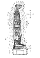
- FIG. 8 is a view corresponding to FIG. 1 of the angle impact driver 301 according to the third embodiment
- FIG. 9 is a view corresponding to FIG. 2 of the third embodiment
- FIG. 10 is a view corresponding to FIG.
- FIG. 5 is a diagram corresponding to FIG. 4 of the third embodiment.
- the angle impact driver 301 of the third embodiment is configured in the same manner as in the first embodiment, except for the configuration of the control circuit board and the sensor board, and the types of signals flowing in some lead wires.
- members similar to those in the first embodiment are denoted by the same reference numerals, and description thereof will be omitted as appropriate.
- the sensor board 380 of the third form includes rotation detection elements 81, 81,... On the front side and switching elements 44, 44,... (Three-phase bridge circuit unit 84) on the rear side, and a control circuit board 336. Does not include the switching elements 44, 44... (Three-phase bridge circuit unit 84) but includes a microcomputer 46 that controls them.
- the switching elements 44, 44,... Are arranged in a ring shape so as to be positioned at each vertex of the hexagon. Small holes 372, 372... And small slits 373, 373... Are provided on the periphery of the sensor substrate 380, and small protrusions projecting from the rear surface other than the recesses 78, 78. 374, 374...
- the sensor substrate 380 has small holes corresponding to the small holes 372 and the lower small slits 373. It is fixed with the projection 374 inserted.
- screw holes (not shown) are provided in portions corresponding to the left and right small slits 373 and 373 in the rear portion of the second insulating member 74, and the sensor substrate 380 is formed by inserting screws 376 into the screw holes.
- the second insulating member 74 is fixed to the rear side.
- coil connection portions 377, 377,... Corresponding to the coils 76, 76,...
- each lead wire 340 (six) wired instead of each lead wire 40 (three) is replaced with an output signal of the switching elements 44, 44,.
- Drive signals 89, 89,... For controlling on / off of the switching elements 44, 44,...
- the three-phase bridge circuit unit 84 (FIG. 11 collectively represents one white arrow) are transmitted.
- the power supply lead wire 52 and the lead wires 340 and 41 are connected on the upper rear surface of the sensor substrate 380.
- the upper rear surface (lead wire connecting portion 380a) of the sensor substrate 380 protrudes upward with respect to the lower disk-shaped portion.
- the sensor substrate 380 is fixed to the brushless motor 16. Further, a switch 14 is disposed between the battery 10 and the brushless motor 16. A switch 14 is disposed between the control circuit board 336 and the brushless motor 16. Further, a stator 58 is disposed between the fan 68 and the switch 14. In addition, the switch 14 is provided between the control circuit board 336 and the plurality of switching elements 44, 44. Further, the switch 14, the brushless motor 16 and the output shaft 20 are arranged on a straight line.
- the rotation state of the motor shaft 60 can be reliably detected with an efficient configuration, and is more compact and easy to grip. It can be configured, and further maintenance work is reduced, so that an unusable period can be prevented.
- the switch 14 since the switch 14 is disposed between the battery 10 and the brushless motor 16, the power supply leads 38, 52,... Can be shortened, the wiring can be easily routed, and even if a load is applied, it is difficult to disconnect. be able to.
- the switch 14 is disposed between the control circuit board 336 and the brushless motor 16, the power supply lead wires 38, 52... And the lead wire 340 between the switch 14 and the control circuit board 336 and the brushless motor 16. , 41... Can be easily wired, and the resistance to heat can be further improved to make the operation of the brushless motor 16 more reliable.
- the stator 58 is disposed between the fan 68 and the switch 14, the cooling efficiency of the brushless motor 16 becomes better, and the diameter of the housing 2 can be made relatively small.
- the switch 14 is provided between the control circuit board 336 and the switching elements 44, 44,..., The switching elements 44, 44,. It becomes less likely to be trapped, and the switching elements 44, 44,... And the control circuit board 436 can be easily cooled, and a more reliable operation can be realized.
- the switch 14 the brushless motor 16, and the output shaft 20 are arranged on a straight line, the size can be reduced.
- [Fourth form] 12 is a view corresponding to FIG. 1 of an angle impact driver 401 according to the fourth embodiment
- FIG. 13 is a view corresponding to FIG. 2 of the fourth embodiment
- FIG. 14 is a view corresponding to FIG.
- the angle impact driver 401 of the fourth embodiment is configured in the same manner as in the second embodiment, except for the configuration of the control circuit board and the sensor board, and the types of signals flowing in some lead wires.
- the same reference numerals are given to the same members as those in the second embodiment, and description thereof will be omitted as appropriate.
- the sensor board 480 of the fourth form includes the rotation detecting elements 81, 81,... On the rear side and the switching elements 44, 44,... (Three-phase bridge circuit unit 84) on the front side. It is configured in the same manner as the three forms of sensor substrate 380 and fixed in the same manner. However, the power supply lead wire 52 and the lead wires 340 and 41 are connected at the lower rear portion of the sensor substrate 480 (the lead wire connecting portion 380a is arranged at the lower portion).
- the sensor board 280 of the second form is fixed in the same manner as the sensor board 480 of the fourth form.
- the control circuit board 436 of the fourth form is configured in the same manner as the control circuit board 336 of the third form except that the connection with the light 26 is direct as in the second form.
- Drive signals 89, 89,... Are transmitted between the control circuit board 436 and the sensor board 480 on the lead wires 340 wired in place of the lead wires 40 (three). Further, in the angle impact driver 401, the brushless motor 216 is disposed in the same manner as in the second embodiment, and the pinion 69, the front bearing 62, the sensor board 480, the stator 58, the fan 68, and the rear bearing 64 are arranged in this order from the front. Are lined up.
- the sensor substrate 480 is fixed to the brushless motor 216.
- a switch 14 is disposed between the battery 10 and the brushless motor 216.
- a switch 14 is disposed between the control circuit board 436 and the brushless motor 216.
- a stator 58 is disposed between the sensor substrate 480 and the switch 14.
- a stator 58 is disposed between the sensor substrate 480 and the switch 14.
- the switch 14 is provided between the control circuit board 436 and the plurality of switching elements 44, 44. Further, the switch 14, the brushless motor 216, and the output shaft 20 are arranged on a straight line.
- the rotation state of the motor shaft 60 can be reliably detected with an efficient configuration, and is more compact and easy to grip. It can be configured, and further maintenance work is reduced, so that an unusable period can be prevented.
- the switch 14 since the switch 14 is disposed between the battery 10 and the brushless motor 216, the power lead wires 38, 52,... Can be shortened, the wiring can be easily routed, and even if a load is applied, it is difficult to disconnect. be able to.
- the switch 14 is disposed between the control circuit board 436 and the brushless motor 216, the power supply lead wires 38, 52,... And the lead wire 340 between the switch 14 and the control circuit board 436 and the brushless motor 216 are arranged. , 41... Can be easily wired, and heat resistance can be further improved, so that the operation of the brushless motor 216 can be made more reliable.
- the stator 58 is disposed between the sensor board 480 and the switch 14, the fan 68 can be placed on the opposite side of the sensor board 480 with the stator 58 interposed therebetween, making it difficult to mix intake and exhaust air, or The air flow can be made smoother by making it difficult for the air to be blocked by hand.
- the switch 14 is provided between the control circuit board 436 and the switching elements 44, 44,..., The switching elements 44, 44,. It is possible to further reduce the possibility of stagnation, and the switching elements 44, 44,... And the control circuit board 436 can be easily cooled, and more reliable operation can be realized.
- the switch 14 since the switch 14, the brushless motor 216, and the output shaft 20 are arranged on a straight line, the size can be reduced.
- the lead wire can be appropriately increased or decreased depending on the product to be implemented.
- the number of housing sections, the number of installed planetary gears, or the number of magnet poles of a brushless motor may be increased or decreased.
- the sensor substrate is fixed to the stator by a projection that enters the hole, by a screw and a screw hole, by a latch by a claw and its latching portion, or a combination thereof.
- the gap between the stator and the sensor substrate may be formed by providing a concave portion on the sensor substrate side, or by forming a concave portion on both sides, or by providing a convex portion at least on either side. It may be formed. Further, the present invention is applied to other rotary impact tools other than the angle impact driver, other impact tools, other angle tools, or other electric tools.
Abstract
Description
この電動ドリルのモータは、回転子のコイルに流れる電流の向きを切り替えることにより回転子を回転させるため、固定子のブラシと接触可能な整流子を回転軸側に有している。
このブラシは、回転する整流子との接触により徐々に摩耗し、何れ電流を充分に通さなくなり寿命となるので、電動ドリルには、ブラシ交換用の突起ないし蓋が設けられる。 As shown in
The motor of this electric drill has a commutator on the rotating shaft side that can come into contact with the brush of the stator in order to rotate the rotor by switching the direction of the current flowing in the coil of the rotor.
The brush gradually wears due to contact with the rotating commutator, and eventually the current is not sufficiently passed, so that the power drill is provided with a brush replacement protrusion or lid.
又、ブラシが寿命となると、新しいブラシに交換するまでモータが回転せず、ビットが回転不能となって電動ドリルが使用不能となってしまう。更に、ブラシの交換を要し、その分手間がかかる。
そこで、本発明は、よりコンパクトで握り易く、メンテナンスの手間が少なくて使用不能期間の発生が防止されるアングル工具を提供することを主な目的とするものである。 Since the conventional electric drill as described above has a commutator and a brush to rotate the rotating shaft of the motor, it is necessary to provide a protrusion and a lid for replacing the brush, and accordingly, it becomes less compact. Depending on their arrangement, it may be difficult to grasp during operation, and the operability may be slightly impaired.
When the brush reaches the end of its life, the motor does not rotate until the brush is replaced with a new brush, and the bit cannot be rotated, and the electric drill cannot be used. Furthermore, the brush needs to be replaced, which takes time.
Therefore, the main object of the present invention is to provide an angle tool that is more compact and easy to grip, requires less maintenance, and prevents the occurrence of an unusable period.
請求項2に記載の発明は、モータ軸を有するブラシレスモータと、前記ブラシレスモータに通電するためのスイッチと、前記ブラシレスモータの回転を伝達され、前記モータ軸に対して角度を持っている出力軸と、前記ブラシレスモータ及び前記スイッチを収容するハウジングと、前記ハウジングに固定されるバッテリと、を有しており、前記バッテリと前記ブラシレスモータの間に、前記スイッチを配置したことを特徴とするものである。
請求項3に記載の発明は、モータ軸を有するブラシレスモータと、前記ブラシレスモータに通電するためのスイッチと、前記ブラシレスモータの回転を伝達され、前記モータ軸に対して角度を持っている出力軸と、前記ブラシレスモータ及び前記スイッチを収容するハウジングと、前記ハウジングの内部に収容される制御回路基板と、を有しており、前記制御回路基板と前記ブラシレスモータの間に、前記スイッチを配置したことを特徴とするものである。
請求項4に記載の発明は、モータ軸を含むロータ、及びステータを有するブラシレスモータと、前記ロータに固定されるモータ軸と、前記モータ軸に固定されるファンと、前記ブラシレスモータに通電するためのスイッチと、前記ブラシレスモータの回転を伝達され、前記モータ軸に対して角度を持っている出力軸と、前記ブラシレスモータ及び前記スイッチを収容するハウジングと、前記ロータの回転を検出するためのセンサ基板と、を有しており、前記センサ基板と前記スイッチの間に、前記ステータを配置したことを特徴とするものである。
請求項5に記載の発明は、モータ軸を含むロータ、及びステータを有するブラシレスモータと、前記モータ軸に固定されるファンと、前記ブラシレスモータに通電するためのスイッチと、前記ブラシレスモータの回転を伝達され、前記モータ軸に対して角度を持っている出力軸と、前記ブラシレスモータ及び前記スイッチを収容するハウジングと、を有しており、前記ファンと前記スイッチの間に、前記ステータを配置したことを特徴とするものである。
請求項6に記載の発明は、ステータ及びロータを有するブラシレスモータと、前記ロータに固定されるモータ軸と、前記モータ軸に固定されるファンと、前記ブラシレスモータに通電するためのスイッチと、前記ブラシレスモータの回転を伝達され、前記モータ軸に対して角度を持っている出力軸と、前記ブラシレスモータ及び前記スイッチを収容するハウジングと、前記ハウジングの内部に収容される制御回路基板と、前記ステータに電気接続される複数のスイッチング素子とを有しており、前記制御回路基板と前記複数のスイッチング素子の間に、前記スイッチが設けられることを特徴とするものである。
請求項7に記載の発明は、ステータ及びロータを有するブラシレスモータと、前記ロータに固定されるモータ軸と、前記モータ軸に固定されるファンと、前記ブラシレスモータに通電するためのスイッチと、前記ブラシレスモータの回転を伝達される出力軸と、前記ブラシレスモータ及び前記スイッチを収容するハウジングと、を有しており、前記スイッチ、前記ブラシレスモータ及び前記出力軸を、一直線上に配置したことを特徴とするものである。 In order to achieve the above object, a first aspect of the present invention is directed to a brushless motor having a motor shaft, a switch for energizing the brushless motor, and rotation of the brushless motor transmitted to the motor shaft. And an output shaft having an angle, a housing for housing the brushless motor and the switch, and a sensor substrate for detecting rotation of the motor shaft, and the sensor substrate on the brushless motor. It is characterized by fixing.
According to a second aspect of the present invention, there is provided a brushless motor having a motor shaft, a switch for energizing the brushless motor, an output shaft that is transmitted with rotation of the brushless motor and has an angle with respect to the motor shaft. And a housing for housing the brushless motor and the switch, and a battery fixed to the housing, and the switch is disposed between the battery and the brushless motor. It is.
According to a third aspect of the present invention, there is provided a brushless motor having a motor shaft, a switch for energizing the brushless motor, an output shaft which is transmitted with rotation of the brushless motor and has an angle with respect to the motor shaft. And a housing for housing the brushless motor and the switch, and a control circuit board housed in the housing, and the switch is disposed between the control circuit board and the brushless motor. It is characterized by this.
According to a fourth aspect of the present invention, a brushless motor having a rotor including a motor shaft and a stator, a motor shaft fixed to the rotor, a fan fixed to the motor shaft, and the brushless motor are energized. A switch for transmitting rotation of the brushless motor, an output shaft having an angle with respect to the motor shaft, a housing for housing the brushless motor and the switch, and a sensor for detecting rotation of the rotor And the stator is arranged between the sensor substrate and the switch.
The invention according to claim 5 is a brushless motor having a rotor including a motor shaft and a stator, a fan fixed to the motor shaft, a switch for energizing the brushless motor, and rotation of the brushless motor. An output shaft that is transmitted and has an angle with respect to the motor shaft, and a housing that houses the brushless motor and the switch, and the stator is disposed between the fan and the switch. It is characterized by this.
The invention according to claim 6 is a brushless motor having a stator and a rotor, a motor shaft fixed to the rotor, a fan fixed to the motor shaft, a switch for energizing the brushless motor, An output shaft that is transmitted with the rotation of the brushless motor and has an angle with respect to the motor shaft, a housing that houses the brushless motor and the switch, a control circuit board that is housed in the housing, and the stator And a plurality of switching elements electrically connected to each other, and the switch is provided between the control circuit board and the plurality of switching elements.
The invention according to claim 7 is a brushless motor having a stator and a rotor, a motor shaft fixed to the rotor, a fan fixed to the motor shaft, a switch for energizing the brushless motor, It has an output shaft to which the rotation of the brushless motor is transmitted, and a housing that houses the brushless motor and the switch, and the switch, the brushless motor, and the output shaft are arranged in a straight line. It is what.
又、請求項2に記載の発明によれば、バッテリとブラシレスモータの間にスイッチを配置したので、配線を取り回し易く、又負荷がかかったとしても断線し難くすることができるし、よりコンパクトで握り易く構成でき、更にメンテナンスの手間が少なくて使用不能期間の発生が防止される。
更に、請求項3に記載の発明によれば、制御回路基板とブラシレスモータの間に、スイッチを配置したので、配線が行い易く、又熱に対する耐性を更に良好にしてブラシレスモータ216の動作をより確実なものとすることができるし、よりコンパクトで握り易く構成でき、更にメンテナンスの手間が少なくて使用不能期間の発生が防止される。
加えて、請求項4に記載の発明によれば、センサ基板とスイッチの間にブラシレスモータのステータを配置したため、風の流れをより円滑にすることができるし、よりコンパクトで握り易く構成でき、更にメンテナンスの手間が少なくて使用不能期間の発生が防止される。
又、請求項5に記載の発明によれば、ファンとスイッチとの間にブラシレスモータのステータを配置したので、ブラシレスモータの冷却効率がより良好となるし、よりコンパクトで握り易く構成でき、更にメンテナンスの手間が少なくて使用不能期間の発生が防止される。
更に、請求項6に記載の発明によれば、制御回路基板とスイッチング素子の間にスイッチが配置されるため、スイッチング素子や制御回路基板の冷却が容易となって、より確実な動作を実現することができるし、よりコンパクトで握り易く構成でき、更にメンテナンスの手間が少なくて使用不能期間の発生が防止される。
加えて、請求項7に記載の発明によれば、スイッチ、ブラシレスモータ及び出力軸を、一直線上に配置したので、よりコンパクトで握り易く構成でき、更にメンテナンスの手間が少なくて使用不能期間の発生が防止される。 According to the first aspect of the present invention, since the sensor substrate is fixed to the brushless motor, the rotation state of the motor shaft can be reliably detected with an efficient configuration, and the sensor can be more compact. It can be configured so that it can be easily gripped, and the maintenance work is reduced, thereby preventing the occurrence of an unusable period.
Further, according to the invention described in
Furthermore, according to the invention described in
In addition, according to the invention described in
According to the invention described in claim 5, since the brushless motor stator is arranged between the fan and the switch, the cooling efficiency of the brushless motor becomes better, and it can be configured more compactly and easily gripped. Occurrence of unusable periods is prevented with less maintenance effort.
Further, according to the invention described in claim 6, since the switch is disposed between the control circuit board and the switching element, the switching element and the control circuit board can be easily cooled, thereby realizing more reliable operation. In addition, it can be configured to be more compact and easy to grip, and further, the maintenance work is reduced and the occurrence of an unusable period is prevented.
In addition, according to the invention described in claim 7, since the switch, the brushless motor, and the output shaft are arranged in a straight line, the switch can be configured more compactly and easily gripped, and further, the maintenance work is less and the inoperable period is generated. Is prevented.
図1は第1形態に係るアングル式の電動工具の一例であるアングルインパクトドライバ1の縦中央断面図であり、図2は図1の前部拡大図であり、図3は図1のA-A断面図である。尚、アングル式とは、モータの軸と出力軸がほぼ90°の角度で交わるものをいう。又、図1における右が、アングルインパクトドライバ1における前となる。
アングルインパクトドライバ1は、その外郭を形成するハウジング2を有している。ハウジング2は、左右で半割可能に形成されており、その左右の各部分は複数のネジ3,3・・及び対応する円筒状のネジ穴部4,4・・により互いに結合されている。
ハウジング2は、中心軸を前後方向とする筒状に形成されている。 [First form]
1 is a longitudinal center sectional view of an
The
The
ハウジング2の後部内であって、バッテリ取付部12の前方には、スイッチ14が収容されている。
ハウジング2の中央部内であって、スイッチ14の前方には、ブラシレスモータ16が収容されている。ハウジング2の内、バッテリ取付部12からブラシレスモータ16の前側外方までの部分は、本体ハウジング17となっている。尚、本体ハウジング17ないしこれに収容される部材により、アングルインパクトドライバ1の本体部が形成される。
ハウジング2の前部内であって、ブラシレスモータ16の前方には、駆動力伝達機構18及び出力軸20が収容されている。ハウジング2の内、駆動力伝達機構18及び出力軸20を覆う部分は、金属製のハンマケース21と、本体ハウジング12前部内に配置されるギヤケース22となっている。ハンマケース21は、固定ネジ21bによって、ギヤケース22に対し固定されている。尚、後述のハンマ93とアンビル94は、ハンマケース21とギヤケース22によって二重に覆われている。
尚、スイッチ14の下側には、ハウジング2から一部露出する状態で、使用者による指等で押す操作が可能であるトリガ形式のスイッチレバー23が設けられており、スイッチレバー23の後方には、ブラシレスモータ16の回転方向を順次切替える正逆反転スイッチ24が、ハウジング2の左右の側面から一部露出する状態で収容されている。スイッチレバー23は、上端23aを回転中心として回転可能に構成されている。
ハウジング2の後部ないし中央部の外側部分(正逆反転スイッチ24より前でブラシレスモータ16の外方より後の外側部分)は、使用者が把持するグリップとして形成されている。グリップには、滑り止め部材(熱可塑性エラストマー)が配置されている。
ブラシレスモータ16の下前方には、前方(出力軸20の下端付近)を照らすライト(LED)26が設けられている。
尚、ハウジング2の後部側面において、ネジ27によりフック28が取り付けられている(図3)。 A
A
A
A driving
A trigger-
The outer part of the rear part or the center part of the housing 2 (the outer part before the forward /
A light (LED) 26 that illuminates the front (near the lower end of the output shaft 20) is provided below the
A
バッテリ10は、後下部において、前方へ押込み可能な取り外し用ボタン30を有する(図3)。取り外し用ボタン30は、弾性体(スプリング)により後方に付勢されており、通常、バッテリ10の他の部分に沿う位置となっている。又、バッテリ10は、前下部において、その周囲に対し出没可能な爪32を有している。取り外し用ボタン30が通常位置にあると、爪32は突出状態となり、取り外し用ボタン30が付勢力に抗して前方へ押されると、爪32は埋没状態となる。尚、バッテリ10は、前面に端子33aを有しており、上下に延びる2つのレール10a,10aを有している。 The
The
バッテリ取付部12に対し、バッテリ10のレール10aをレール係合部に沿わせた状態で、バッテリ10を下方から上へスライドさせると、爪32が係合凹部34に係合して、バッテリ10が取り付けられる。このとき、バッテリ10の端子33aは、バッテリ取付部12の対応する端子33bと係合し接触する。 The
When the
制御回路基板36と、その前方のスイッチ14の間には、電源リード線38,38が配線されている。又、制御回路基板36と、その前方のブラシレスモータ16に固定された後述のセンサ基板80との間には、回転制御用のリード線40,40・・と、回転検出信号用のリード線41,41・・が施されている。更に、制御回路基板36と、その前方のライト26の間には、リード線42a,42bが配線されている。リード線42a,42bの間には、互いに結合可能なコネクタ42c,42dが介装されている。コネクタ42c,42dは、ハウジング2のリブ42e内において結合状態で取り付けられている。ライト用のリード線42bの中央部は、後述のモータハウジング54外側の上方ないし前方に配置されている。尚、制御回路基板36と、バッテリ取付部12の端子33bの間には、電源リード線43,43が施されている。バッテリ取付部12の端子33bにおける電気は、電源リード線43,43、制御回路基板36及び電源リード線38,38を介して、スイッチ14に通じている。
又、制御回路基板36には、複数(6個)のスイッチング素子44,44・・、及びマイコン46が搭載されている。
スイッチング素子44,44・・は、左右に分かれて3個ずつ上下に並ぶように配置されている。スイッチング素子44,44・・は、マイコン46の左右において、3個ずつ配置されている。 As shown mainly in FIG. 3, a
Power supply leads 38 are provided between the
In addition, a plurality (six) of switching
The switching
スイッチ14は、スイッチ本体50と、その下面から下方へ突出するプランジャ51を有している。プランジャ51が上方に押し込まれると、スイッチ14がオンとなり、押し込まれず通常の位置にあると、スイッチ14がオフとなる。プランジャ51の下側において、スイッチレバー23の後部が接触している。
スイッチ14と、その前方のブラシレスモータ16に固定された後述のセンサ基板80との間には、電源リード線52,52が施されている。 The
The
Power supply leads 52 and 52 are provided between the
ロータ56は、ブラシレスモータ16の回転軸であるモータ軸60と、モータ軸60の前部を軸支する前軸受62と、モータ軸60の後端部を軸支する後軸受64と、モータ軸60の中央部においてモータ軸60と一体的に設けられるロータコア(回転子鉄心)及び磁石66を含む。尚、前軸受62の後側には、塵や熱等の排出のためのファン68が、モータ軸60と一体的に設けられている。又、モータ軸60の前端部には、ピニオン69が固定されている。
前軸受62は、ギヤケース22の後部中央において保持されており、後軸受64は、モータハウジング54の後端部内側中央において保持されている。
ステータ58は、前後方向を軸方向とした筒状の固定子鉄心70と、ステータコア(固定子鉄心)70の前側に配置される円盤状の第1絶縁部材72と、ステータコア70の後側ないしステータコア70内に配置される円盤状の第2絶縁部材74と、ステータコア70に対して、第1絶縁部材72及び第2絶縁部材74を介して巻かれる複数(ここでは6個)のコイル76,76・・を含む。
更に、第2絶縁部材74の後面には、他の後面部分に対して前方へ窪む凹部78,78・・が、それぞれ放射方向に延びる状態で複数設けられている。 The
The
The
The
Further, the rear surface of the second insulating
センサ基板80は、第2絶縁部材74における各凹部78を除く後面とセンサ基板80の略平坦な前面の対応部分が接するように配置されており、各凹部78により第2絶縁部材74とセンサ基板80の間に隙間が形成されている。尚、センサ基板80の上端部は、モータハウジング54の後上部に形成された孔から上に出ており、各リード線40,41や各電源リード線52が接続される部分となっている。又、センサ基板80の中央部には、モータ軸60を通す孔が開けられている。
スイッチ14外方の本体ハウジング17には、図示しない吸気口が形成されており、ファン68により当該吸気口からハウジング2内へ導入された外気は、第2絶縁部材74とセンサ基板80の間の隙間を介してブラシレスモータ16へと流入可能である。尚、ファン68外方の本体ハウジング17には、図示しない排気口が形成されている。
又、センサ基板80は、回転検出センサとしての、複数(ここでは3個)の回転検出素子81,81・・(図4参照)を有している。
回転検出素子81,81・・は、センサ基板80の前面上部において互いに等間隔となるように配置されている。 A disc-shaped
The
An air inlet (not shown) is formed in the
The
The
駆動回路82は、電源回路部83と、スイッチング素子44,44・・を含む三相ブリッジ回路部84と、スイッチング素子44,44・・等を制御するマイコン46を備えている。 FIG. 4 shows a
The
制御回路基板36は、マイコン46又はスイッチング素子44,44・・(三相ブリッジ回路部84)の少なくとも何れかを有するので、ブラシレスモータ16の制御を行う基板となっている。
尚、センサ基板80における各種の素子やリード線は、リフロー方式等により、表面(センサ基板80後面)からの突出量が抑制された状態で実装されている(表面実装、SMT:Surface Mount Technology)。
リフロー方式は、センサ基板80へ所定パターンに係るハンダの印刷(あるいはディスペンサによる部品搭載位置への接着剤の塗布)を施し、チップマウンタで各種の素子やリード線の載置を行い、リフロー炉で熱を加えてハンダを溶融し、各種の素子やリード線を固定する、という手順を踏む方式であり、センサ基板80に素子等載置用の貫通孔を開ける必要がないし、センサ基板80に素子等の足を貫通させて反対側にそれぞれハンダを付ける必要がなくなる。 The
Since the
Various elements and lead wires on the
In the reflow method, solder printing according to a predetermined pattern is applied to the sensor substrate 80 (or adhesive is applied to a component mounting position by a dispenser), various elements and lead wires are placed by a chip mounter, and the reflow furnace is used. This is a method in which the solder is melted by applying heat to fix various elements and lead wires, and it is not necessary to open through holes for mounting elements and the like in the
内歯ギヤ100は、ギヤケース22内側において回転不能に取り付けられている。
各遊星歯車102は、ギヤケース22の後部内側に配置された、ブラシレスモータ16のモータ軸60のピニオン69に噛み合っている。 The
The
Each
ギヤケース24内に配されるネジ穴部4,4の内側には、スピンドル91を受けるスピンドル軸受110が設置されている。スピンドル軸受110は、ギヤケース22の中程であって遊星歯車機構90の前方に保持されている。
スピンドル91の円盤状部91aの後面には、遊星歯車102の各ピン104の前端部に対応するピン孔が複数(ピン104の数だけ)設けられる。そして、各ピン104は、前端部をピン孔に入れた状態で、円盤状部91aの後側に設けられる。
各遊星歯車102は、対応するピン104の周りで回転可能である状態で、ピン104に周設される。
又、スピンドル91の円盤状部91aの後面から前方への穴であるスピンドル穴91bが設けられており、スピンドル穴91b内には、ブラシレスモータ16のモータ軸60及びピニオン69の先端部(遊星歯車102に噛み合っていない部分)が、スピンドル穴91bの周面と間隙を置いた状態で入る。 The
A spindle bearing 110 that receives the
A plurality of pin holes (as many as the number of pins 104) corresponding to the front end portions of the
Each
Further, a
一方、スプリング92の後端部は、ワッシャ115に接触しており、ワッシャ115は、スピンドル軸受110に接触している。
尚、ハンマ93とスピンドル91の前部との間には、打撃時にハンマ93を主に前後方向に案内するボール116,116が介装されている。 The
On the other hand, the rear end portion of the
Note that
延設部94a,94aの前側には、アンビル94を軸周りに回転自在且つ軸方向に変位不能に支持するアンビル軸受120が設けられている。アンビル軸受120は、ギヤケース22の前部であってハンマ93の前方に保持されている。
又、アンビル94の後部中央には、後面から前方への穴である後穴94bが開けられており、後穴94bには、回転打撃力を伝達可能な状態で、スピンドル91の前端部が入れられている。
更に、アンビル94の前部には、シャフト95の後部を回転力伝達可能に受け入れる、前面から後方への穴である前穴94cが設けられている。アンビル94の前穴94cとシャフト95の後部は、スプライン構造で連係されている。 The
An anvil bearing 120 is provided on the front side of the extending
A
Furthermore, the front part of the
シャフト95における、かさ歯部95a以外の部分の周りには、シャフト軸受122,122が前後に配置されており、シャフト95は、自身の軸周りで回転可能に支持されている。各シャフト軸受122は、ハンマケース21に対して取り付けられている。シャフト軸受122,122の間には、筒状のスペーサ124が設けられている。 The
出力軸20の上端部の周りには、上出力軸受130が設けられている。又、出力軸20のかさ歯部20aの下側には、下出力軸受132が設けられている。出力軸20は、上出力軸受130及び下出力軸受132により、自身の軸周りで回転可能に支持されている。
又、出力軸20の先端部(下端部)には、下面から上方への穴を含み、図示しないビットを装着可能なチャック部20bが開けられている。チャック部20bの中央部には、ビットの小凹部に対応するチャックボール134,134が、前後に設けられている。
チャック部20bの外側は筒状のスリーブ136で覆われており、チャック部20b下部外面とスリーブ136下部内面との間には下方に開放される間隙が形成されていて、その間隙には、スプリング137と、その下面に接触するワッシャ138が設けられている。ワッシャ138は、その下面内側に当たる状態でチャック部20cの先端部外面に埋められた止め輪140により係止されている。尚、ハンマケース21はスリーブ136の外方において下方への開口部21aを有しており、開口部21aの外側ないし下側には、開口部21aを覆う弾性材製のバンパー142が配置されている。
ハンマケース21ないしその前部内の部材(ギヤケース22より前方の部材、シャフト95から出力軸20まで)は、アダプタ化(モジュール化)可能であり、当該モジュールは、ハンマケース21後部をギヤケース22の外側に配置し、シャフト95の後部をアンビル94の前穴94cに入れることで組み付け可能である。 The
An upper output bearing 130 is provided around the upper end portion of the
Further, a
The outside of the
The
使用者がハウジング2(本体ハウジング17)の外側を把持してスイッチレバー23を上方へ引くと、プランジャ51の上部がスイッチ本体50に入ってスイッチ14がオンとなり、バッテリ10からブラシレスモータ16(駆動回路82)への給電がなされ、制御回路基板36やセンサ基板80による制御のもとでロータ56が回転する。
ロータ56の回転力は、内歯ギヤ100内を自転しながら走る遊星歯車102,102・・により減速されたうえで、ピン104,104・・を介し、スピンドル91に伝わる。
スピンドル91は、アンビル94及びシャフト95を回転させると共に、アンビル94において所定閾値以上のトルクを受けた場合にハンマ93を前後に揺動(打撃)するように案内する。打撃時には、スプリング92による緩衝作用がハンマ93(やスピンドル91)に働く。
シャフト95は、かさ歯部95a,20aを介して、モータ軸60と90°の角度を持っている出力軸20を回転(打撃)し、チャック部20bに装着されたビットを回転(打撃)する。 An example of the operation of the
When the user grips the outside of the housing 2 (main body housing 17) and pulls the
The rotational force of the
The
The
よって、ブラシ交換時にブラシにアクセスするために、ハウジング2において外方に突出する突出部や蓋を設ける必要がなく、ハウジング2ひいてはアングルインパクトドライバ1をコンパクトに構成することができ、余分な突出をなくして操作性を一層良好にできる。
又、ブラシの交換が不要となり、メンテナンス性を良好にできるし、寿命となったブラシを新しいブラシに交換するまで使用不能となる事態を回避できるし、ブラシを予め用意しておく必要がなくなる。
更に、ブラシを要するモータに比べ、ブラシレスモータ16ではモータ軸60をより速く(より所定時間当たりの回転数を多く)することが容易であり、より強力な出力軸20における出力を確保することが可能となる。
加えて、センサ基板80がブラシレスモータ16の第2絶縁部材74の後側に固定されるので、モータ軸60の隣接位置に回転検出手段を配することができ、モータ軸60の回転状態の検出を効率の良い構成により確実に行うことができる。 The
Therefore, in order to access the brush when the brush is replaced, it is not necessary to provide a protruding portion or a cover that protrudes outward in the
In addition, it is not necessary to replace the brush, the maintenance can be improved, the situation where the brush becomes unusable until the replaced brush is replaced with a new brush can be avoided, and it is not necessary to prepare the brush in advance.
Furthermore, compared with a motor that requires a brush, the
In addition, since the
よって、電源リード線38,52・・を短くすることができ、配線を取り回し易く、又衝撃や振動等の負荷がかかったとしても断線し難くすることができる。 The
Therefore, the power supply leads 38, 52,... Can be shortened, the wiring can be easily routed, and even if a load such as impact or vibration is applied, it is difficult to disconnect.
よって、スイッチ14と、制御回路基板36やブラシレスモータ16との、電源リード線38,52・・やリード線40,41・・による配線が行い易い。
又、制御回路基板36が振動や熱を発するブラシレスモータ16から離れるので、制御回路基板36に振動や熱の影響が及んで制御回路基板36が誤動作する可能性を低減して、ブラシレスモータ16の動作をより確実なものとすることができる。尚、制御回路基板36自体(各スイッチング素子44やマイコン46)も動作時に発熱するので、発熱源を分散して熱に対する耐性を向上することができる。 Further, the
Therefore, it is easy to perform wiring between the
Further, since the
よって、ファン68により起こされた風がステータ58を通過し易く、ブラシレスモータ16の冷却効率がより良好となる。更に、スイッチ14の操作部とファン68が離れるので、手で覆われ難い位置に吸気口を配置し易く、ステータ58の冷却効率の向上に寄与する。又、ファン68、スイッチ14、ステータ58が一直線上に並ぶので、ハウジング2の径を比較的に小さくすることができる。 Still further, the
Therefore, the wind generated by the
よって、ハウジング2の径を比較的に小さくして、アングルインパクトドライバ1をよりコンパクトにすることができる。 In addition, the
Therefore, the diameter of the
図5は第2形態に係るアングルインパクトドライバ201の図1相当図であり、図6は第2形態に係る図2相当図であり、図7は第2形態に係る図3相当図である。
第2形態のアングルインパクトドライバ201は、ブラシレスモータ、ライト、制御回路基板、ファン、センサ基板、吸気口、排気口及びリード線の配置を除き、第1形態と同様に構成される。以下、第1形態と同様の部材には同じ符号を付し、適宜説明を省略する。 [Second form]
FIG. 5 is a view corresponding to FIG. 1 of the
The
即ち、第2絶縁部材74が前に配置され、第1絶縁部材72が後に配置される。
又、センサ基板280が第2絶縁部材74の前に固定される。尚、センサ基板280は、前後と上下が逆であることを除き、センサ基板80と同様に構成される。即ち、各リード線40,41や各電源リード線52との接続部が後下に配置されている。又、各回転検出素子81が後面下部に配置されている。
更に、ファン68が、第1絶縁部材72の後に配置されている。
尚、吸気口は、ブラシレスモータ16の前部外方のハウジング2の部分に形成され、排気口は、スイッチ14の後側(正逆反転スイッチ24)外方のハウジング2の部分に形成される。
又、ライト26は、制御回路基板236の前側下部に配置されており、制御回路基板236に対し、端子242a,242aによって直接接続されている。制御回路基板236は、ライト26に関する配線を除き、制御回路基板36と同様に構成される。 The
That is, the second insulating
In addition, the
Further, a
The intake port is formed in a portion of the
The light 26 is disposed at the lower front side of the
又、バッテリ10とブラシレスモータ216の間に、スイッチ14を配置したので、電源リード線38,52・・を短くすることができ、配線を取り回し易く、又負荷がかかったとしても断線し難くすることができる。
更に、制御回路基板236とブラシレスモータ216の間に、スイッチ14を配置しているため、スイッチ14と、制御回路基板236やブラシレスモータ216との、電源リード線38,52・・やリード線40,41・・による配線が行い易く、又熱に対する耐性を更に良好にしてブラシレスモータ216の動作をより確実なものとすることができる。 In the
Further, since the
Further, since the
加えて、スイッチ14、ブラシレスモータ216及び出力軸20を、一直線上に配置したので、コンパクト化を図れる。 Further, the
In addition, since the
図8は第3形態に係るアングルインパクトドライバ301の図1相当図であり、図9は第3形態の図2相当図であり、図10は第3形態の図3相当図であり、図11は第3形態の図4相当図である。
第3形態のアングルインパクトドライバ301は、制御回路基板及びセンサ基板の構成や、一部のリード線内を流れる信号の種類を除き、第1形態と同様に構成される。以下、第1形態と同様の部材には同じ符号を付し、適宜説明を省略する。 [Third embodiment]
8 is a view corresponding to FIG. 1 of the
The
センサ基板380の周縁には、小孔372,372・・や小スリット373,373・・が設けられると共に、第2絶縁部材74には、凹部78,78・・以外の後面から突出する小突起374,374・・が、小孔373,373・・や下の小スリット373と対応するように設けられており、センサ基板380は、各小孔372や下の小スリット373に、対応する小突起374を入れた状態で固定されている。又、第2絶縁部材74後部における、左右の小スリット373,373に対応する部分には、図示しないネジ孔が設けられており、そのネジ孔にそれぞれネジ376を入れることにより、センサ基板380が第2絶縁部材74の後側に固定されている。更に、第2絶縁部材74の後面には、コイル76,76・・に対応するコイル接続部377,377・・が形成されており、センサ基板380と各コイル76は各コイル接続部377において電気的に接続されている。尚、第1形態のセンサ基板80は、第3形態のセンサ基板380と同様に固定されている。
制御回路基板336とセンサ基板380の間において、各リード線40(3本)の代わりに配線された各リード線340(6本)は、スイッチング素子44,44・・の出力信号の代わりに、三相ブリッジ回路部84におけるスイッチング素子44,44・・のオン/オフをそれぞれ制御する駆動信号89,89・・(図11はまとめて1つの白矢印で表す)を伝える。電源リード線52やリード線340,41は、センサ基板380の後面上部において接続されている。センサ基板380の後面上部(リード線接続部380a)は、これより下部の円盤状部分に対し上方に突出している。 The
Between the
又、バッテリ10とブラシレスモータ16の間に、スイッチ14を配置したので、電源リード線38,52・・を短くすることができ、配線を取り回し易く、又負荷がかかったとしても断線し難くすることができる。
更に、制御回路基板336とブラシレスモータ16の間に、スイッチ14を配置しているため、スイッチ14と、制御回路基板336やブラシレスモータ16との、電源リード線38,52・・やリード線340,41・・による配線が行い易く、又熱に対する耐性を更に良好にしてブラシレスモータ16の動作をより確実なものとすることができる。 In the
Further, since the
Further, since the
又、制御回路基板336とスイッチング素子44,44・・の間に、スイッチ14が設けられるので、駆動により発熱するスイッチング素子44,44・・と制御回路基板336を互いに離隔させることができ、熱がこもることが少なくなるし、スイッチング素子44,44・・や制御回路基板436の冷却が容易となって、より確実な動作を実現することができる。
加えて、スイッチ14、ブラシレスモータ16及び出力軸20を、一直線上に配置したので、コンパクト化を図れる。 Furthermore, since the
Further, since the
In addition, since the
図12は第4形態に係るアングルインパクトドライバ401の図1相当図であり、図13は第4形態の図2相当図であり、図14は第4形態の図3相当図である。
第4形態のアングルインパクトドライバ401は、制御回路基板及びセンサ基板の構成や、一部のリード線内を流れる信号の種類を除き、第2形態と同様に構成される。以下、第2形態と同様の部材には同じ符号を付し、適宜説明を省略する。 [Fourth form]
12 is a view corresponding to FIG. 1 of an
The
第4形態の制御回路基板436は、ライト26との接続が第2形態と同様に直接的であることを除き、第3形態の制御回路基板336と同様に構成される。尚、制御回路基板436とセンサ基板480の間における、各リード線40(3本)に代わり配線された各リード線340において、駆動信号89,89・・が伝達される。
更に、アングルインパクトドライバ401では、第2形態と同様にブラシレスモータ216が配置されており、又、前からピニオン69、前軸受62、センサ基板480、ステータ58、ファン68、後軸受64の順で並べられている。 The
The
Further, in the
又、バッテリ10とブラシレスモータ216の間に、スイッチ14を配置したので、電源リード線38,52・・を短くすることができ、配線を取り回し易く、又負荷がかかったとしても断線し難くすることができる。
更に、制御回路基板436とブラシレスモータ216の間に、スイッチ14を配置しているため、スイッチ14と、制御回路基板436やブラシレスモータ216との、電源リード線38,52・・やリード線340,41・・による配線が行い易く、又熱に対する耐性を更に良好にしてブラシレスモータ216の動作をより確実なものとすることができる。 In the
Further, since the
Further, since the
又、制御回路基板436とスイッチング素子44,44・・の間に、スイッチ14が設けられるので、駆動により発熱するスイッチング素子44,44・・と制御回路基板436を互いに離隔させることができ、熱がこもる可能性をより低くできるし、スイッチング素子44,44・・や制御回路基板436の冷却が容易となって、より確実な動作を実現することができる。
加えて、スイッチ14、ブラシレスモータ216及び出力軸20を、一直線上に配置したので、コンパクト化を図れる。 Furthermore, since the
Further, since the
In addition, since the
尚、本発明は上記形態に限定されず、例えば次のような変更を適宜施すことができる。
制御回路基板やセンサ基板における、各種リード線や各種素子について、上述の接続位置や搭載位置と異なる位置で接続しあるいは搭載して良く、又接続位置を複数箇所に分けても良い。各種のリード線の配置も様々に変更することができ、例えば2本の電源リード線を上下に配置する(1本を上方に配置すると共にもう1本を下方に配置する)ことができる。
更に、各種リード線や各種素子、ブラシレスモータのコイル等について、数を増減することができるし、種類を増減することもできる。特に、リード線は、実施の製品に応じて、適宜増減することができる。同様に、ハウジングの区分の数や、遊星歯車の設置数、あるいはブラシレスモータの磁石の極数を増減して良い。又、スイッチレバーのスイッチの形式を変更したり、バッテリをリチウムイオン電池以外の充電池あるいは一次電池に変更したりする等、各種部材の数や配置、材質、大きさ、形式、種類等を適宜変更することができる。
ステータに対するセンサ基板の固定を、孔に入る突起によるものや、ネジとネジ孔によるもの、爪とその係止部による係止によるものや、これらの組合せ等により行う。
ステータとセンサ基板の間の隙間につき、センサ基板側に凹部を設けることで形成しても良いし、双方に凹部を設けることで形成しても良いし、少なくとも何れかに凸部を設けることで形成しても良い。
又、アングルインパクトドライバ以外の他の回転打撃工具、あるいは他の打撃工具、他のアングル工具又は他の電動工具に、本発明を適用する。 [Modification examples of the first to fourth embodiments]
In addition, this invention is not limited to the said form, For example, the following changes can be given suitably.
Various lead wires and various elements on the control circuit board and sensor board may be connected or mounted at positions different from the above-mentioned connection positions and mounting positions, and the connection positions may be divided into a plurality of locations. The arrangement of various lead wires can also be changed variously. For example, two power supply lead wires can be arranged vertically (one is arranged at the top and the other is arranged at the bottom).
Further, the number of various leads, various elements, coils of a brushless motor, and the like can be increased or decreased, and the types can be increased or decreased. In particular, the lead wire can be appropriately increased or decreased depending on the product to be implemented. Similarly, the number of housing sections, the number of installed planetary gears, or the number of magnet poles of a brushless motor may be increased or decreased. Also, change the number, arrangement, material, size, type, type, etc. of various members as appropriate, such as changing the switch type of the switch lever or changing the battery to a rechargeable battery or primary battery other than a lithium ion battery. Can be changed.
The sensor substrate is fixed to the stator by a projection that enters the hole, by a screw and a screw hole, by a latch by a claw and its latching portion, or a combination thereof.
The gap between the stator and the sensor substrate may be formed by providing a concave portion on the sensor substrate side, or by forming a concave portion on both sides, or by providing a convex portion at least on either side. It may be formed.
Further, the present invention is applied to other rotary impact tools other than the angle impact driver, other impact tools, other angle tools, or other electric tools.
Claims (7)
- モータ軸を有するブラシレスモータと、
前記ブラシレスモータに通電するためのスイッチと、
前記ブラシレスモータの回転を伝達され、前記モータ軸に対して角度を持っている出力軸と、
前記ブラシレスモータ及び前記スイッチを収容するハウジングと、
前記モータ軸の回転を検出するためのセンサ基板と、
を有しており、
前記ブラシレスモータに、前記センサ基板を固定した
ことを特徴とするアングル工具。 A brushless motor having a motor shaft;
A switch for energizing the brushless motor;
An output shaft to which rotation of the brushless motor is transmitted and having an angle with respect to the motor shaft;
A housing that houses the brushless motor and the switch;
A sensor substrate for detecting rotation of the motor shaft;
Have
An angle tool characterized in that the sensor substrate is fixed to the brushless motor. - モータ軸を有するブラシレスモータと、
前記ブラシレスモータに通電するためのスイッチと、
前記ブラシレスモータの回転を伝達され、前記モータ軸に対して角度を持っている出力軸と、
前記ブラシレスモータ及び前記スイッチを収容するハウジングと、
前記ハウジングに固定されるバッテリと、
を有しており、
前記バッテリと前記ブラシレスモータの間に、前記スイッチを配置した
ことを特徴とするアングル工具。 A brushless motor having a motor shaft;
A switch for energizing the brushless motor;
An output shaft to which rotation of the brushless motor is transmitted and having an angle with respect to the motor shaft;
A housing that houses the brushless motor and the switch;
A battery fixed to the housing;
Have
An angle tool, wherein the switch is arranged between the battery and the brushless motor. - モータ軸を有するブラシレスモータと、
前記ブラシレスモータに通電するためのスイッチと、
前記ブラシレスモータの回転を伝達され、前記モータ軸に対して角度を持っている出力軸と、
前記ブラシレスモータ及び前記スイッチを収容するハウジングと、
前記ハウジングの内部に収容される制御回路基板と、
を有しており、
前記制御回路基板と前記ブラシレスモータの間に、前記スイッチを配置した
ことを特徴とするアングル工具。 A brushless motor having a motor shaft;
A switch for energizing the brushless motor;
An output shaft to which rotation of the brushless motor is transmitted and having an angle with respect to the motor shaft;
A housing that houses the brushless motor and the switch;
A control circuit board housed in the housing;
Have
An angle tool characterized in that the switch is arranged between the control circuit board and the brushless motor. - モータ軸を含むロータ、及びステータを有するブラシレスモータと、
前記ロータに固定されるモータ軸と、
前記モータ軸に固定されるファンと、
前記ブラシレスモータに通電するためのスイッチと、
前記ブラシレスモータの回転を伝達され、前記モータ軸に対して角度を持っている出力軸と、
前記ブラシレスモータ及び前記スイッチを収容するハウジングと、
前記ロータの回転を検出するためのセンサ基板と、
を有しており、
前記センサ基板と前記スイッチの間に、前記ステータを配置した
ことを特徴とするアングル工具。 A brushless motor having a rotor including a motor shaft and a stator;
A motor shaft fixed to the rotor;
A fan fixed to the motor shaft;
A switch for energizing the brushless motor;
An output shaft to which rotation of the brushless motor is transmitted and having an angle with respect to the motor shaft;
A housing that houses the brushless motor and the switch;
A sensor substrate for detecting rotation of the rotor;
Have
An angle tool, wherein the stator is disposed between the sensor substrate and the switch. - モータ軸を含むロータ、及びステータを有するブラシレスモータと、
前記モータ軸に固定されるファンと、
前記ブラシレスモータに通電するためのスイッチと、
前記ブラシレスモータの回転を伝達され、前記モータ軸に対して角度を持っている出力軸と、
前記ブラシレスモータ及び前記スイッチを収容するハウジングと、
を有しており、
前記ファンと前記スイッチの間に、前記ステータを配置した
ことを特徴とするアングル工具。 A brushless motor having a rotor including a motor shaft and a stator;
A fan fixed to the motor shaft;
A switch for energizing the brushless motor;
An output shaft to which rotation of the brushless motor is transmitted and having an angle with respect to the motor shaft;
A housing that houses the brushless motor and the switch;
Have
An angle tool characterized in that the stator is arranged between the fan and the switch. - ステータ及びロータを有するブラシレスモータと、
前記ロータに固定されるモータ軸と、
前記モータ軸に固定されるファンと、
前記ブラシレスモータに通電するためのスイッチと、
前記ブラシレスモータの回転を伝達され、前記モータ軸に対して角度を持っている出力軸と、
前記ブラシレスモータ及び前記スイッチを収容するハウジングと、
前記ハウジングの内部に収容される制御回路基板と、
前記ステータに電気接続される複数のスイッチング素子と
を有しており、
前記制御回路基板と前記複数のスイッチング素子の間に、前記スイッチが設けられる
ことを特徴とするアングル工具。 A brushless motor having a stator and a rotor;
A motor shaft fixed to the rotor;
A fan fixed to the motor shaft;
A switch for energizing the brushless motor;
An output shaft to which rotation of the brushless motor is transmitted and having an angle with respect to the motor shaft;
A housing that houses the brushless motor and the switch;
A control circuit board housed in the housing;
A plurality of switching elements electrically connected to the stator;
An angle tool, wherein the switch is provided between the control circuit board and the plurality of switching elements. - ステータ及びロータを有するブラシレスモータと、
前記ロータに固定されるモータ軸と、
前記モータ軸に固定されるファンと、
前記ブラシレスモータに通電するためのスイッチと、
前記ブラシレスモータの回転を伝達される出力軸と、
前記ブラシレスモータ及び前記スイッチを収容するハウジングと、
を有しており、
前記スイッチ、前記ブラシレスモータ及び前記出力軸を、一直線上に配置した
ことを特徴とする電動工具。 A brushless motor having a stator and a rotor;
A motor shaft fixed to the rotor;
A fan fixed to the motor shaft;
A switch for energizing the brushless motor;
An output shaft to which the rotation of the brushless motor is transmitted;
A housing that houses the brushless motor and the switch;
Have
The power tool, wherein the switch, the brushless motor, and the output shaft are arranged on a straight line.
Priority Applications (3)
| Application Number | Priority Date | Filing Date | Title |
|---|---|---|---|
| CN201490000573.8U CN205184693U (en) | 2013-04-04 | 2014-02-05 | Angle instrument and electric tool |
| DE212014000099.8U DE212014000099U1 (en) | 2013-04-04 | 2014-02-05 | Angle tool and electrical tool |
| US14/763,626 US20150364972A1 (en) | 2013-04-04 | 2014-02-05 | Angle tool and electric tool |
Applications Claiming Priority (2)
| Application Number | Priority Date | Filing Date | Title |
|---|---|---|---|
| JP2013-078810 | 2013-04-04 | ||
| JP2013078810A JP6018010B2 (en) | 2013-04-04 | 2013-04-04 | Angle tool |
Publications (1)
| Publication Number | Publication Date |
|---|---|
| WO2014162772A1 true WO2014162772A1 (en) | 2014-10-09 |
Family
ID=51658076
Family Applications (1)
| Application Number | Title | Priority Date | Filing Date |
|---|---|---|---|
| PCT/JP2014/052678 WO2014162772A1 (en) | 2013-04-04 | 2014-02-05 | Angle tool and electric tool |
Country Status (5)
| Country | Link |
|---|---|
| US (1) | US20150364972A1 (en) |
| JP (1) | JP6018010B2 (en) |
| CN (1) | CN205184693U (en) |
| DE (1) | DE212014000099U1 (en) |
| WO (1) | WO2014162772A1 (en) |
Cited By (1)
| Publication number | Priority date | Publication date | Assignee | Title |
|---|---|---|---|---|
| US20150340921A1 (en) * | 2014-05-26 | 2015-11-26 | Makita Corporation | Electric power tool |
Families Citing this family (17)
| Publication number | Priority date | Publication date | Assignee | Title |
|---|---|---|---|---|
| WO2016031719A1 (en) * | 2014-08-29 | 2016-03-03 | 日立工機株式会社 | Electric working machine |
| US10404136B2 (en) * | 2015-10-14 | 2019-09-03 | Black & Decker Inc. | Power tool with separate motor case compartment |
| WO2017082360A1 (en) * | 2015-11-11 | 2017-05-18 | 株式会社マキタ | Binding machine |
| JP6697895B2 (en) * | 2016-02-19 | 2020-05-27 | 株式会社マキタ | Work tools |
| JP6758853B2 (en) * | 2016-02-22 | 2020-09-23 | 株式会社マキタ | Angle tool |
| CN110382167B (en) * | 2017-03-07 | 2021-11-05 | 株式会社牧田 | Tool holding device, electric tool, and impact tool |
| JP7020789B2 (en) * | 2017-03-24 | 2022-02-16 | 株式会社マキタ | Right angle drill |
| US11418094B2 (en) | 2017-03-31 | 2022-08-16 | Koki Holdings Co., Ltd. | Electric tool |
| WO2018198671A1 (en) * | 2017-04-27 | 2018-11-01 | 工機ホールディングス株式会社 | Electrically powered tool |
| CN110944799B (en) * | 2017-07-24 | 2021-11-26 | 费斯托工具有限责任公司 | Power tool and method |
| JP7220362B2 (en) * | 2017-09-25 | 2023-02-10 | パナソニックIpマネジメント株式会社 | Electric tool |
| JP6987667B2 (en) | 2018-02-23 | 2022-01-05 | 株式会社マキタ | Impact tool |
| JP7190511B2 (en) * | 2018-12-26 | 2022-12-15 | 株式会社マキタ | electric work machine |
| CN112238411B (en) * | 2019-07-19 | 2024-02-20 | 株式会社牧田 | Electric tool and rotary tool |
| GB2583796A (en) * | 2019-11-15 | 2020-11-11 | Black & Decker Inc | Motor terminals facing gear case in a power tool |
| JP7462273B2 (en) * | 2020-07-31 | 2024-04-05 | パナソニックIpマネジメント株式会社 | Impact rotary tool |
| TWI750884B (en) * | 2020-11-04 | 2021-12-21 | 朝程工業股份有限公司 | electrical tools |
Citations (5)
| Publication number | Priority date | Publication date | Assignee | Title |
|---|---|---|---|---|
| US20010031179A1 (en) * | 1998-04-23 | 2001-10-18 | Potter Christine H. | Two speed right angle drill |
| JP2007295773A (en) * | 2006-04-27 | 2007-11-08 | Makita Corp | Dc brushless motor |
| JP2007330065A (en) * | 2006-06-09 | 2007-12-20 | Makita Corp | Dc brushless motor for power tool |
| JP2011062770A (en) * | 2009-09-16 | 2011-03-31 | Hitachi Koki Co Ltd | Power tool |
| JP2013022681A (en) * | 2011-07-21 | 2013-02-04 | Hitachi Koki Co Ltd | Electric tool |
Family Cites Families (10)
| Publication number | Priority date | Publication date | Assignee | Title |
|---|---|---|---|---|
| JP2007014147A (en) * | 2005-06-30 | 2007-01-18 | Fujitsu General Ltd | Electric motor |
| US7786626B2 (en) * | 2006-11-03 | 2010-08-31 | Pacific Bioscience Laboratories, Inc. | Oscillating motor for a personal care appliance |
| JP2008173716A (en) * | 2007-01-18 | 2008-07-31 | Max Co Ltd | Electric power tool having brushless motor |
| JP5088614B2 (en) * | 2007-09-28 | 2012-12-05 | 日立工機株式会社 | Electric tool |
| JP5143522B2 (en) | 2007-10-11 | 2013-02-13 | 株式会社マキタ | electric drill |
| JP5589255B2 (en) * | 2008-02-26 | 2014-09-17 | 日立工機株式会社 | Portable power tools |
| JP5182562B2 (en) * | 2008-02-29 | 2013-04-17 | 日立工機株式会社 | Electric tool |
| EP2296848A2 (en) * | 2008-05-29 | 2011-03-23 | Hitachi Koki CO., LTD. | Electric power tool |
| JP5472683B2 (en) * | 2009-05-11 | 2014-04-16 | 日立工機株式会社 | Electric tool |
| JP6270510B2 (en) * | 2014-01-30 | 2018-01-31 | 東京パーツ工業株式会社 | DC brushless motor |
-
2013
- 2013-04-04 JP JP2013078810A patent/JP6018010B2/en active Active
-
2014
- 2014-02-05 CN CN201490000573.8U patent/CN205184693U/en not_active Expired - Lifetime
- 2014-02-05 DE DE212014000099.8U patent/DE212014000099U1/en not_active Expired - Lifetime
- 2014-02-05 WO PCT/JP2014/052678 patent/WO2014162772A1/en active Application Filing
- 2014-02-05 US US14/763,626 patent/US20150364972A1/en not_active Abandoned
Patent Citations (5)
| Publication number | Priority date | Publication date | Assignee | Title |
|---|---|---|---|---|
| US20010031179A1 (en) * | 1998-04-23 | 2001-10-18 | Potter Christine H. | Two speed right angle drill |
| JP2007295773A (en) * | 2006-04-27 | 2007-11-08 | Makita Corp | Dc brushless motor |
| JP2007330065A (en) * | 2006-06-09 | 2007-12-20 | Makita Corp | Dc brushless motor for power tool |
| JP2011062770A (en) * | 2009-09-16 | 2011-03-31 | Hitachi Koki Co Ltd | Power tool |
| JP2013022681A (en) * | 2011-07-21 | 2013-02-04 | Hitachi Koki Co Ltd | Electric tool |
Cited By (1)
| Publication number | Priority date | Publication date | Assignee | Title |
|---|---|---|---|---|
| US20150340921A1 (en) * | 2014-05-26 | 2015-11-26 | Makita Corporation | Electric power tool |
Also Published As
| Publication number | Publication date |
|---|---|
| CN205184693U (en) | 2016-04-27 |
| DE212014000099U1 (en) | 2015-11-12 |
| JP6018010B2 (en) | 2016-11-02 |
| JP2014200884A (en) | 2014-10-27 |
| US20150364972A1 (en) | 2015-12-17 |
Similar Documents
| Publication | Publication Date | Title |
|---|---|---|
| JP6018010B2 (en) | Angle tool | |
| JP2016215373A (en) | Angle tool | |
| US11090784B2 (en) | Screw-tightening power tool | |
| JP6016602B2 (en) | Electric tool | |
| WO2010035563A1 (en) | Power tool | |
| CN106998110B (en) | Electric tool | |
| JP2007283447A (en) | Power tool | |
| JP4974054B2 (en) | Electric tool | |
| JP5354363B2 (en) | Electric tool | |
| JP2012254519A (en) | Power tool, and communication plug for the power tool | |
| JP5332163B2 (en) | Electric tool | |
| JP2017087330A (en) | Electric power tool | |
| JP2016153157A (en) | Electric power tool | |
| CN111590506B (en) | Electric tool | |
| JP2013000863A (en) | Electric tool | |
| JP6626944B2 (en) | Electric tool | |
| JP6417250B2 (en) | Electric tool | |
| JP7129871B2 (en) | impact tools and power tools | |
| JP2014172145A (en) | Screw tightening electric tool | |
| JP2017148936A (en) | Screwdriver | |
| JP6335345B2 (en) | Screw tightening electric tool | |
| JP2020188631A (en) | Electric work machine | |
| JP4947490B2 (en) | Electric tool | |
| JP2018111206A (en) | Screw tightening electric tool | |
| JP2014100787A (en) | Power tool |
Legal Events
| Date | Code | Title | Description |
|---|---|---|---|
| WWE | Wipo information: entry into national phase |
Ref document number: 201490000573.8 Country of ref document: CN |
|
| 121 | Ep: the epo has been informed by wipo that ep was designated in this application |
Ref document number: 14780010 Country of ref document: EP Kind code of ref document: A1 |
|
| WWE | Wipo information: entry into national phase |
Ref document number: 14763626 Country of ref document: US |
|
| WWE | Wipo information: entry into national phase |
Ref document number: 2120140000998 Country of ref document: DE Ref document number: 212014000099 Country of ref document: DE |
|
| 122 | Ep: pct application non-entry in european phase |
Ref document number: 14780010 Country of ref document: EP Kind code of ref document: A1 |