WO2014162571A1 - 画像生成装置、端末装置、画像生成システム、画像生成方法、情報処理方法、プログラムおよびコンピュータが読み取り可能な記録媒体 - Google Patents
画像生成装置、端末装置、画像生成システム、画像生成方法、情報処理方法、プログラムおよびコンピュータが読み取り可能な記録媒体 Download PDFInfo
- Publication number
- WO2014162571A1 WO2014162571A1 PCT/JP2013/060389 JP2013060389W WO2014162571A1 WO 2014162571 A1 WO2014162571 A1 WO 2014162571A1 JP 2013060389 W JP2013060389 W JP 2013060389W WO 2014162571 A1 WO2014162571 A1 WO 2014162571A1
- Authority
- WO
- WIPO (PCT)
- Prior art keywords
- image
- guide
- movement
- movement history
- terminal device
- Prior art date
- Legal status (The legal status is an assumption and is not a legal conclusion. Google has not performed a legal analysis and makes no representation as to the accuracy of the status listed.)
- Ceased
Links
Images


Classifications
-
- G—PHYSICS
- G01—MEASURING; TESTING
- G01C—MEASURING DISTANCES, LEVELS OR BEARINGS; SURVEYING; NAVIGATION; GYROSCOPIC INSTRUMENTS; PHOTOGRAMMETRY OR VIDEOGRAMMETRY
- G01C21/00—Navigation; Navigational instruments not provided for in groups G01C1/00 - G01C19/00
- G01C21/26—Navigation; Navigational instruments not provided for in groups G01C1/00 - G01C19/00 specially adapted for navigation in a road network
- G01C21/34—Route searching; Route guidance
- G01C21/36—Input/output arrangements for on-board computers
- G01C21/3626—Details of the output of route guidance instructions
- G01C21/3647—Guidance involving output of stored or live camera images or video streams
-
- G—PHYSICS
- G08—SIGNALLING
- G08G—TRAFFIC CONTROL SYSTEMS
- G08G1/00—Traffic control systems for road vehicles
- G08G1/09—Arrangements for giving variable traffic instructions
- G08G1/0962—Arrangements for giving variable traffic instructions having an indicator mounted inside the vehicle, e.g. giving voice messages
- G08G1/0967—Systems involving transmission of highway information, e.g. weather, speed limits
- G08G1/096708—Systems involving transmission of highway information, e.g. weather, speed limits where the received information might be used to generate an automatic action on the vehicle control
- G08G1/096716—Systems involving transmission of highway information, e.g. weather, speed limits where the received information might be used to generate an automatic action on the vehicle control where the received information does not generate an automatic action on the vehicle control
-
- G—PHYSICS
- G08—SIGNALLING
- G08G—TRAFFIC CONTROL SYSTEMS
- G08G1/00—Traffic control systems for road vehicles
- G08G1/09—Arrangements for giving variable traffic instructions
- G08G1/0962—Arrangements for giving variable traffic instructions having an indicator mounted inside the vehicle, e.g. giving voice messages
- G08G1/0967—Systems involving transmission of highway information, e.g. weather, speed limits
- G08G1/096733—Systems involving transmission of highway information, e.g. weather, speed limits where a selection of the information might take place
- G08G1/096741—Systems involving transmission of highway information, e.g. weather, speed limits where a selection of the information might take place where the source of the transmitted information selects which information to transmit to each vehicle
-
- G—PHYSICS
- G08—SIGNALLING
- G08G—TRAFFIC CONTROL SYSTEMS
- G08G1/00—Traffic control systems for road vehicles
- G08G1/09—Arrangements for giving variable traffic instructions
- G08G1/0962—Arrangements for giving variable traffic instructions having an indicator mounted inside the vehicle, e.g. giving voice messages
- G08G1/0967—Systems involving transmission of highway information, e.g. weather, speed limits
- G08G1/096766—Systems involving transmission of highway information, e.g. weather, speed limits where the system is characterised by the origin of the information transmission
- G08G1/096775—Systems involving transmission of highway information, e.g. weather, speed limits where the system is characterised by the origin of the information transmission where the origin of the information is a central station
Definitions
- the present invention relates to an image generation device, a terminal device, an image generation system, an image generation method, an information processing method, a program, and a computer-readable recording medium.
- a communication device mounted on the leading moving body transmits a traveling locus of the leading moving body to the communication device of the succeeding moving body, and
- a communication device sets a route based on a travel locus received from a leading mobile body to guide a subsequent mobile body to a route on which the leading mobile body is traveling (see, for example, Patent Document 1 below). ).
- the subsequent moving body cannot be guided to the route on which the leading moving body is traveling, and the following moving body may not be able to follow the traveling locus of the leading moving body.
- the communication device of the subsequent mobile body has a function of setting a route based on the travel locus received from the communication device of the leading mobile body. Therefore, in the prior art, when the communication device of the subsequent mobile body does not have such a function, the subsequent mobile body cannot be guided to the route on which the leading mobile body is traveling, and the subsequent mobile body is not connected to the leading mobile body. It was difficult to follow the trajectory.
- an image generation apparatus includes an image acquisition unit that acquires an image including a guide point, and a movement history acquisition unit that acquires a movement history of a moving object at the guide point.
- a terminal device comprising: an image acquisition unit that acquires an image including a guidance point; a movement history acquisition unit that acquires a movement history of a moving body at the guidance point; Transmitting means for transmitting the image and the movement history after passing through a point is provided.
- the terminal device is a terminal device mounted on a succeeding mobile body following the leading mobile body, wherein movement information based on a movement history at a guide point of the leading mobile body is obtained as the guidance information.
- Guide image acquisition means for acquiring a guide image generated by being superimposed on an image including a point, and display means for displaying the guide image.
- An image generation system is an image generation system including a terminal device mounted on a mobile body and a server device provided so as to be communicable with the terminal device.
- An image acquisition means for acquiring an image including a point; a movement history acquisition means for acquiring a movement history of a moving object at the guidance point; and after the moving object passes through the guidance point, the image and the movement history are Transmitting means for transmitting to the server device, wherein the server device receives the image transmitted by the transmitting means and the movement history, the image received by the receiving means, and the movement And generating means for generating a guide image in which movement information of the moving body based on the movement history is superimposed on the image based on the history.
- An image generation method is an image generation method executed by a computer, an image acquisition step for acquiring an image including a guide point, and a movement history of a moving body at the guide point.
- An information processing method is an information processing method executed by a computer, an image acquisition step of acquiring an image including a guide point, and a movement history of a moving body at the guide point. It includes a movement history acquisition step and a transmission step of transmitting the image and the movement history after the moving body has passed through the guide point.
- the program according to the invention of claim 12 causes a computer to execute the image generation method according to claim 10.
- program according to the invention of claim 13 causes a computer to execute the information processing method of claim 11.
- a computer-readable recording medium records the program according to claim 12.
- a computer-readable recording medium records the program according to claim 13.
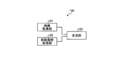
- FIG. 1 is a block diagram showing a functional configuration of an image generation apparatus according to an embodiment of the present invention.
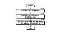
- FIG. 2 is a flowchart illustrating an example of processing performed by the image generation apparatus according to the present embodiment.
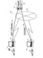
- FIG. 3 is an explanatory diagram illustrating an overview of the image generation system according to the first embodiment.
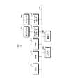
- FIG. 4 is a block diagram illustrating a hardware configuration of the server apparatus according to the first embodiment.
- FIG. 5 is a block diagram illustrating a hardware configuration of the terminal device according to the first embodiment.
- FIG. 6 is a flowchart illustrating an example of processing performed by the server apparatus according to the first embodiment.
- FIG. 7 is an explanatory diagram (part 1) illustrating an example of a guidance image according to the first embodiment.
- FIG. 8 is an explanatory diagram (part 2) illustrating an example of a guide image according to the first embodiment.
- FIG. 9 is an explanatory diagram illustrating an overview of the image generation system according to the second embodiment.
- FIG. 1 is a block diagram showing a functional configuration of an image generation apparatus according to an embodiment of the present invention.
- the image generation apparatus 100 illustrated in FIG. 1 is provided in a state in which it can communicate with terminal apparatuses mounted on a plurality of mobile bodies that travel to a common destination via a network.
- the network may include a LAN (Local Area Network), a WAN (Wide Area Network), a mobile phone network, and the like.
- the image generation apparatus 100 includes an image acquisition unit 101, a movement history acquisition unit 102, and a generation unit 103.
- the image acquisition unit 101 acquires an image including a guide point.
- the guide point can be a point where the moving body can take a plurality of patterns of movement contents.
- the guide point can include an intersection where the moving body can move in a plurality of directions. That is, in this case, the moving body can take a plurality of patterns of movement contents indicating in which direction it has moved.
- the moving body can also enter a facility along the road and return to the road from this facility. Therefore, the entrance / exit of such a facility can also be used as a guide point.
- a road shoulder is provided on the road, the moving body can also stop at this road shoulder. Therefore, such a shoulder can also be used as a guide point.
- a terminal device mounted on a leading mobile body among a plurality of mobile bodies heading to a common destination includes a camera that captures a landscape around the leading mobile body.
- the leading moving body is a moving body that is predetermined as a leading moving body by users of a plurality of moving bodies heading to a common destination.
- a so-called “drive recorder” camera can be used as the camera.
- the camera of the leading mobile terminal device captures the scenery around the leading mobile body while power is supplied (for example, while the leading mobile body is moving). Then, the leading mobile terminal device outputs an image photographed by this camera to the image acquisition unit 101 via the network.
- the leading mobile terminal device is configured to be able to acquire current location information indicating the current location of the leading mobile body by GPS or the like, and outputs the acquired current location information to the image acquisition unit 101 via the network.
- the image acquisition unit 101 receives from the leading mobile terminal device based on the current location information received from the leading mobile terminal device and the map data stored in the image generating device 100 in advance by the manufacturer of the image generating device 100. An image captured when the leading mobile body is located around the guide point is identified from the images. Thereby, the image acquisition part 101 can acquire the image containing the guidance point image
- the leading mobile terminal device determines that the leading mobile body is located around the guidance point based on the current location information of the leading mobile body and the map data.
- an image captured at the point may be output to the image acquisition unit 101.
- the data amount of the image output by the lead mobile terminal device can be reduced.
- the image including the guide point is not limited to the actual image actually taken.
- the image including the guide point may be an image including the guide point on the map. That is, in this case, a map representing a predetermined range including the guide point is an image including the guide point.
- the image acquisition unit 101 acquires an image including guide points around the leading mobile body based on the current location information received from the leading mobile terminal device and the map data stored in advance in the image generating apparatus 100. can do. Further, if map data is stored in the leading mobile terminal device, the leading mobile terminal device displays an image including guide points around the leading mobile body based on the current location information of the leading mobile body and the map data. Can be acquired.
- the movement history acquisition unit 102 acquires the movement history of the moving body at the guide point.
- the movement history can represent the contents of movement performed by the moving body at the guide point. For example, when the mobile body makes a left turn at an intersection, the left turn at this intersection is the movement history.
- the movement history For example, when a moving body enters and exits a facility along a road, the entry and exit to this facility becomes the movement history. Further, for example, when the moving body stops at the road shoulder, the stop at the road shoulder becomes the movement history.
- the leading mobile terminal device is configured to be able to acquire current location information indicating the current location of the mobile object, and outputs the acquired current location information to the movement history acquisition unit 102 via the network. Then, for example, the movement history acquisition unit 102 determines each guidance from the transition of the current location of the leading mobile body based on the current location information received from the leading mobile terminal device and the map data stored in advance in the image generating device 100. The movement history of the leading mobile body at the point can be acquired.
- the leading mobile terminal device is based on the current location information of the leading mobile body and the map data. It is good also as acquiring the movement history of the leading mobile body in this guidance point, and outputting the acquired movement history to the movement history acquisition part 102. In this case, the processing load for acquiring the movement history of the leading mobile body at each guide point from the transition of the current location of the leading mobile body by the image generating apparatus 100 can be reduced.
- the generation unit 103 performs image processing to generate a guide image in which the movement information based on the movement history acquired by the movement history acquisition unit 102 is superimposed on the image acquired by the image acquisition unit 101.
- the movement information represents movement history with characters and images. For example, in the case of a movement history of a left turn at an intersection, the movement information can be a character “left turn” or an image of a left arrow “ ⁇ ”.
- the generation unit 103 generates an image in which movement information corresponding to the movement contents performed by the leading mobile body at the guidance point is superimposed on the actual image taken by the camera of the leading mobile terminal device around the guidance point. To do. In addition, the generation unit 103 generates an image in which movement information corresponding to the content of movement performed by the leading mobile body at this guidance point is superimposed on a map around the guidance point.
- the generation unit 103 can generate a guide image indicating the content of movement performed by the leading mobile body at the guide point.
- the guide image includes an actual image of the taken guide point and a map of the guide point, it is possible to indicate which guide point the guide image corresponds to. Therefore, the generation unit 103 can generate a guide image indicating how the leading mobile body has moved at which guide point.
- the guidance image generated by the generation unit 103 is transmitted via a network to terminal devices mounted on a plurality of moving bodies that travel to a common destination.
- terminal devices mounted on a plurality of moving bodies that travel to a common destination For example, users of a plurality of moving bodies heading to a common destination can know how the leading moving body has moved at which guide point, and follow the movement trajectory that the leading moving body has moved. Is possible.
- the guide image generated by the generation unit 103 is held by the image generation apparatus 100 in a state in which terminal devices mounted on a plurality of mobile bodies heading for a common destination are accessible via the network. May be. Also in this case, users of a plurality of moving bodies heading to a common destination can know how the leading moving body has moved at which guide point, and follow the movement trajectory in which the leading moving body has moved. It becomes possible.
- FIG. 2 is a flowchart illustrating an example of processing performed by the image generation apparatus according to the present embodiment.
- the image generating apparatus 100 performs the process shown in FIG. 2 when the moving body is located around the guidance point.
- the image generating apparatus 100 acquires an image including a guide point (step S201). Subsequently, the image generating apparatus 100 acquires the movement history of the moving object at the guidance point (step S202). Then, the image generating apparatus 100 generates a guide image in which the movement information based on the movement history acquired in step S202 is superimposed on the image including the guide point acquired in step S201 (step S203), and is shown in FIG. The process ends.
- the image generation apparatus 100 transmits the guide image generated in step S203, for example, to terminal devices mounted on a plurality of moving bodies that travel to a common destination via the network. Or in a state accessible from other terminal devices.
- the image generation apparatus 100 acquires and guides the guide image generated by the image generation apparatus 100 by the terminal apparatus of the subsequent mobile body that follows the leading mobile terminal in the plurality of mobile bodies that travel to the common destination. As long as it has a displayable configuration, it is possible to notify the user of the subsequent moving body at which guide point the leading moving body has moved according to the guide image, and the movement locus of the leading moving body has moved. Can be traced.
- Example 1 A first embodiment of the present invention described below is an example in which the present invention is applied to a server device installed in a data center or the like in a state where it can communicate with a terminal device (for example, a navigation device) mounted on a vehicle. is there.
- a terminal device for example, a navigation device
- FIG. 3 is an explanatory diagram illustrating an overview of the image generation system according to the first embodiment.
- the image generation system 300 according to the first embodiment includes a server device 310, a terminal device 321, and a terminal device 322.
- the server device 310 is realized by, for example, a workstation installed in a data center as described above. Further, for example, the terminal device 321 is realized by a navigation device mounted on a leading vehicle 331 that is a leading role, and the terminal device 322 is realized by a navigation device that is mounted on a subsequent vehicle 332 that is a leading role.
- the leading vehicle 331 and the following vehicle 332 are vehicles that are supposed to go to a common destination by users of these vehicles. In addition, it is possible for the user of these vehicles to arbitrarily set which of the vehicles destined for the common destination is the leading vehicle.
- the server device 310 can communicate with the terminal device 321 and the terminal device 322 via the network 340.
- the network 340 for example, a LAN, a WAN, a mobile phone network, or the like is used.
- the terminal device 321 includes a camera 514 (see FIG. 5 for details) that captures the scenery around the leading vehicle 331.
- the camera 514 of the terminal device 321 can capture a landscape around the leading vehicle 331 with a moving image.
- the camera 514 of the terminal device 321 shoots a road (for example, an intersection) where the leading vehicle 331 has moved, facilities along the road, a shoulder provided on the road, and the like.
- the terminal device 321 can acquire current location information indicating the current location of the leading vehicle 331 using GPS (see reference numeral 516 in FIG. 5) or the like.
- the terminal device 321 associates image data indicating the image captured by the camera 514 with the current location information of the leading vehicle 331 when the image is captured (hereinafter referred to as “leading vehicle information”).
- the data is transmitted to the server device 310 (see reference numeral 351 in FIG. 3).
- the terminal device 321 transmits the leading vehicle information at that time to the server device 310 at predetermined intervals (for example, every second).
- the terminal device 321 may also transmit route information indicating a route to the destination to the server device 310.
- the server device 310 has a leading vehicle information database (hereinafter, the database is abbreviated as “DB”) 311. Each time the server device 310 receives the leading vehicle information transmitted from the terminal device 321, the server device 310 sequentially stores the leading vehicle information in the leading vehicle information DB 311.
- DB leading vehicle information database
- the server device 310 acquires the movement history of the leading vehicle 331 from the leading vehicle information stored in the leading vehicle information DB 311. That is, since the leading vehicle information includes the current location information of the leading vehicle 331 at each time point as described above, the server device 310 displays the change of the current location of the leading vehicle 331 at each time point as the movement history of the leading vehicle 331. Get as.
- map data 312 is stored in the server device 310.
- the map data 312 includes guide point position information indicating the position of each guide point.
- the server device 310 determines whether the leading vehicle 331 has passed the guidance point. In this determination, for example, the server device 310 determines whether or not a position that coincides with the guidance point is included in the transition of the current location of the leading vehicle 331 from when the leading vehicle 331 passes the previous guidance point to the present. Determine whether.
- the server 310 When the server device 310 determines that the leading vehicle 331 has passed the guidance point, the server 310 reads out an image taken immediately before passing the guidance point from the leading vehicle information DB 311. For example, the server device 310 captures an image that was captured a predetermined time before (for example, 5 seconds before) an image that was captured when the current location of the leading vehicle 331 coincided with the guidance point, immediately before the passage of the guidance point. Read out as an image. Further, the server device 310 may read an image taken at a position a predetermined distance (for example, 5 m) before the guide point as an image taken immediately before passing through the guide point. And the server apparatus 310 produces
- a predetermined time before for example, 5 seconds before
- the server device 310 When the server device 310 generates the guide image, the server device 310 transmits guide image information indicating the guide image to the terminal device 322 of the following vehicle 332 (see reference numeral 352 in FIG. 3).
- the server device 310 may generate a guide image using a map image without using the actual image captured by the camera of the terminal device 321.
- the server device 310 determines that the leading vehicle 331 has passed the guidance point
- the server device 310 reads data representing a map around the guidance point (hereinafter referred to as “guidance point neighboring map data”) from the map data 312.
- the server device 310 generates a guidance image in which movement information indicating the movement content of the leading vehicle 331 at this guidance point is superimposed on the map image around the guidance point represented by the read guidance point vicinity map data.
- the guide image information indicating the guide image is transmitted to the terminal device 322 of the succeeding vehicle 332.
- the server device 310 receives the guide image information indicating both the guide image using the actual image captured by the camera 514 of the terminal device 321 and the guide image using the map image around the guide point, and the terminal device of the following vehicle 332. You may transmit to 322.
- the terminal device 322 includes a display 513 that can display an arbitrary image (see FIG. 5 for details). Upon receiving the guide image information from the server device 310, the terminal device 322 displays a guide image based on the guide image information on the display 513. Therefore, the user of the following vehicle 332 can know how and where the leading vehicle 331 has moved from the guidance image displayed on the display 513 of the terminal device 322, and the movement trajectory of the leading vehicle 331 can be determined. It is possible to follow.
- the server device 310 may generate a guide image in which the current location of the following vehicle 332 is plotted (marked so that the user can understand) on the map. In this way, the user of the succeeding vehicle 332 can grasp the positional relationship between the guide point represented by the guide image and the current location of the succeeding vehicle 332, and more easily follow the movement trajectory of the leading vehicle 331.
- the terminal device 322 is configured to be able to acquire current location information indicating the current location of the following vehicle 332 by using GPS (see reference numeral 516 in FIG. 5) or the like, similarly to the terminal device 321.
- the terminal device 322 transmits current location information indicating the current location of the subsequent vehicle 332 at that time to the server device 310 at a predetermined interval (for example, every second).
- the server device 310 determines the current location of the guide point and the subsequent vehicle 332.
- the scale of the map image is set so that the map includes both, and the map is plotted at a position indicating the current location of the following vehicle 332 on the map.
- the server device 310 may transmit a guide image including a map image in which the current location of the following vehicle 332 is plotted to the terminal device 321 of the leading vehicle 331 as described above. In this way, the user of the leading vehicle 331 can grasp the current location of the following vehicle 332.
- the server device 310 may generate a guide image in which the current location of the leading vehicle 331 is plotted on the map in addition to the current location of the following vehicle 332.
- the server device 310 sets the scale of the map image so that the map includes all of the guidance point, the current location of the following vehicle 332, and the current location of the leading vehicle 331. Then, the server device 310 plots the guidance point, the position indicating the current location of the following vehicle 332, and the position indicating the current location of the leading vehicle 331 on this map.
- the server device 310 may transmit this guidance image to the terminal device 321 of the leading vehicle 331.
- FIG. 4 is a block diagram illustrating a hardware configuration of the server apparatus according to the first embodiment.
- the server device 310 includes a CPU (Central Processing Unit) 401, a ROM (Read Only Memory) 402, a RAM (Random Access Memory) 403, a magnetic disk drive 404, a magnetic disk 405, An optical disk drive 406, an optical disk 407, an input device 408, and a communication I / F 409 are provided. Further, the respective components 401 to 409 are connected by a bus 420.
- a CPU Central Processing Unit
- ROM Read Only Memory
- RAM Random Access Memory
- magnetic disk drive 404 a magnetic disk drive
- An optical disk drive 406, an optical disk 407, an input device 408, and a communication I / F 409 are provided. Further, the respective components 401 to 409 are connected by a bus 420.
- the CPU 401 controls the entire server device 310.
- Various programs such as a boot program and a guide image generation program are recorded in the ROM 402. These programs are not limited to the ROM 402, and may be recorded on a non-volatile recording medium such as the magnetic disk 405 or the optical disk 407.
- the RAM 403 is used as a work area for the CPU 401.
- the CPU 401 controls the entire server device 310 by executing various programs recorded in the ROM 402 and the like while using the RAM 403 as a work area. Note that the processing results obtained by executing the various programs are temporarily recorded in, for example, the RAM 403 and read out as necessary. Further, the above processing result may be recorded in a nonvolatile memory such as the magnetic disk 405 or the optical disk 407.
- the magnetic disk drive 404 controls reading and writing of data with respect to the magnetic disk 405 according to the control of the CPU 401. Data written under the control of the magnetic disk drive 404 is recorded on the magnetic disk 405.
- the magnetic disk 405 For example, as the magnetic disk 405, HD (Hard Disk) or FD (Flexible Disk) can be used.
- the optical disc drive 406 controls reading and writing of data with respect to the optical disc 407 according to the control of the CPU 401.
- the optical disc 407 is a detachable recording medium from which data is read according to the control of the optical disc drive 406.
- a CD Compact Disc
- DVD can be used as the optical disc 407.
- a writable recording medium can be used as the optical disc 407.
- the removable recording medium may be a memory card or the like.
- the map data 312 includes roads that include nodes and links and that indicate the roads on which a moving body (for example, a vehicle) can move and the above-described guide points.
- this road data includes information indicating the attributes of the road corresponding to each link, such as the length (distance), road width, road type (highway, toll road, general road, private road) for each link. It is.
- the road data includes information indicating the position of each node (guide point).
- the map data 312 includes image data drawn using features relating to facilities and other terrain (mountains, rivers, land).
- the server device 310 can generate a map image drawn two-dimensionally or three-dimensionally on the display screen of the display 513 of the terminal device 322 using this image data.
- the input device 408 includes a remote controller, a keyboard, a mouse, a touch panel, and the like provided with a plurality of keys for inputting characters, numerical values, various instructions, and the like.
- the input device 408 inputs a signal corresponding to a key selected by a user (for example, an administrator of the server apparatus 310) into the apparatus.
- the communication I / F 409 is connected to the network 340 and functions as an interface between the network 340 and the server device 310 (for example, the CPU 401).
- the communication I / F 409 is realized by a modem or the like.
- the functions of the image acquisition unit 101, the movement history acquisition unit 102, and the generation unit 103 illustrated in FIG. 1 can be realized by the CPU 401, the ROM 402, the RAM 403, the communication I / F 409, and the like.
- FIG. 5 is a block diagram illustrating a hardware configuration of the terminal device according to the first embodiment.
- the terminal devices 321 and 322 include a CPU 501, a ROM 502, a RAM 503, a magnetic disk drive 504, a magnetic disk 505, an optical disk drive 506, an optical disk 507, an audio I / F 508, and a speaker. 509, a microphone 510, an input device 511, a video I / F 512, a display 513, a camera 514, a communication I / F 515, a GPS unit 516, and various sensors 517.
- the components 501 to 517 are connected by a bus 520, respectively.
- the CPU 501 governs overall control of the terminal devices 321 and 322.
- Various programs such as a boot program are recorded in the ROM 502. These programs are not limited to the ROM 502, and may be recorded on a non-volatile recording medium such as the magnetic disk 505 or the optical disk 507.
- the RAM 503 is used as a work area for the CPU 501.
- the CPU 501 governs overall control of the terminal devices 321 and 322 by executing various programs recorded in the ROM 502 or the like while using the RAM 503 as a work area. Note that the processing results obtained by executing the various programs are temporarily recorded in, for example, the RAM 503 and read out as necessary. Further, the above processing result may be recorded in a nonvolatile memory such as the magnetic disk 505 or the optical disk 507.
- the magnetic disk drive 504 controls reading and writing of data with respect to the magnetic disk 505 according to the control of the CPU 501. Data written under the control of the magnetic disk drive 504 is recorded on the magnetic disk 505.
- the magnetic disk 505 For example, as the magnetic disk 505, HD or FD can be used.
- the optical disk drive 506 controls reading and writing of data with respect to the optical disk 507 according to the control of the CPU 501.
- the optical disk 507 is a detachable recording medium from which data is read according to the control of the optical disk drive 506.
- a CD or a DVD can be used as the optical disc 507.
- a writable recording medium can be used as the optical disc 507.
- the removable recording medium may be an MO (Magneto Optical Disk), a memory card, or the like.
- map data can be cited as in the server device 310.
- this map data includes roads that are composed of nodes and links and that can be moved by a moving body (for example, a vehicle), and road data that indicates the aforementioned guide points.
- this road data includes information indicating the attributes of the road corresponding to each link, such as the length (distance), road width, road type (highway, toll road, general road, private road) for each link. It is.
- the road data includes information indicating the position of each node (guide point).
- the map data 312 includes image data drawn using features relating to facilities and other terrain (mountains, rivers, land).
- the server device 310 uses the image data to render the terminal devices 321 and 321 two-dimensionally or three-dimensionally on the display screen of the display 513.
- the map data is recorded on the magnetic disk 505 or the optical disk 507.
- the terminal devices 321 and 322 acquire map data from the server device 310 via the network 340 by the communication I / F 515, record the acquired map data in the RAM 503, the magnetic disk 505, and the like, and read them as necessary. May be.
- the audio I / F 508 is connected to a speaker 509 for audio output and a microphone 510 that converts the input audio into an audio signal.
- the sound I / F 508 outputs a predetermined sound (for example, an alarm sound) from the speaker 509 or outputs a sound signal input from the microphone 510 to the CPU 501 in accordance with the control of the CPU 501.
- Examples of the input device 511 include a remote controller having a plurality of keys for inputting characters, numerical values, various instructions, a keyboard, a mouse, a touch panel, and the like.
- the input device 511 inputs a signal corresponding to the key selected by the user into the apparatus.
- a display 513 is connected to the video I / F 512.
- the video I / F 512 includes a graphic controller that controls the entire display 513, a buffer memory such as a VRAM (Video RAM) that temporarily records image information that can be displayed immediately, and image data output from the graphic controller.
- the control IC is configured to control the display of the display 513.
- the display 513 displays icons (for example, own position marks), cursors, menus, windows, or various data such as characters and images.
- icons for example, own position marks
- cursors for example, own position marks
- menus for example, a CRT, a TFT liquid crystal display, a plasma display, an organic EL display, or the like can be used.
- the camera 514 captures the inside of the host vehicle or the vicinity of the host vehicle, and inputs this shooting data to the video I / F 512.
- the communication I / F 515 is connected to the network 340 via wireless and functions as an interface between the terminal devices 321 and 322 and the CPU 501. Further, the communication I / F 515 may receive TV traffic, radio broadcast, road traffic information such as traffic congestion and traffic regulations distributed from the VICS center, and the like.
- VICS is a registered trademark.
- the communication I / F 515 includes an FM tuner, a VICS / beacon receiver, a wireless terminal device, and other terminal devices 321 and 322.
- the GPS unit 516 receives a GPS signal (radio wave) from a GPS satellite and measures the current location of the vehicle.
- the current location measured by the GPS unit 516 is used when the current location of the vehicle is specified by the CPU 501 together with output values of various sensors 517 described later.
- Various sensors 517 output information for measuring the behavior of the vehicle.
- the various sensors 517 include an acceleration sensor, an angular velocity sensor, a vehicle speed pulse sensor, and the like.
- the output values of the various sensors 517 are used by the CPU 501 for specifying the current location of the vehicle, detecting acceleration, detecting angular velocity, calculating azimuth variation, and the like.
- FIG. 6 is a flowchart illustrating an example of processing performed by the server apparatus according to the first embodiment.
- the server device 310 receives a notification from the terminal device 321 to the destination common to the terminal device 322, the server device 310 performs the process illustrated in FIG.
- the terminal device 321 is a terminal device mounted on the leading vehicle 331
- the terminal device 322 is a terminal device mounted on the following vehicle 332 that goes to the common destination, the destination
- Information indicating the route from the current location of the leading vehicle 331 to this destination is included.
- the server apparatus 310 first determines whether or not the leading vehicle 331 has passed the guidance point (step S601). This determination method is as described above. If it is determined that the leading vehicle 331 has not passed the guidance point (step S601: No), the server apparatus 310 proceeds to the process of step S609.
- the server device 310 acquires the image taken immediately before passing the guidance point by reading it from the leading vehicle information DB 311 (step S602). .
- the server device 310 acquires the movement history of the leading vehicle 331 from the leading vehicle information DB 311 (step S603). And the server apparatus 310 produces
- the server device 310 generates a first guidance image in which the movement information generated in step S604 is superimposed on the image taken immediately before the leading vehicle 331 acquired in step S602 passes the guidance point. (Step S605).
- the server device 310 acquires the guidance point surrounding map data around the guidance point through which the leading vehicle 331 has passed by reading from the map data 312 (step S606). And the server apparatus 310 produces
- the server device 310 transmits guide image information indicating the first guide image generated in step S605 and the second guide image generated in step S607 to the terminal device 322 of the following vehicle 332 (step S608).
- the server device 310 determines whether or not the leading vehicle 331 has arrived at the destination (step S609). If it determines with the leading vehicle 331 having arrived at the destination (step S609: Yes), the server apparatus 310 will complete
- the server device 310 In the case of the processing described above, every time the leading vehicle 331 passes through the guidance point, the server device 310 generates a guidance image and transmits guidance image information to the subsequent vehicle 332. In this case, the amount of processing of the server device 310 may be enormous. Further, from the user of the following vehicle 332, the guide image displayed on the terminal device 322 is frequently updated when the guide image information is sent even though the current location of the leading vehicle 331 has not changed so much. It may feel annoying. Furthermore, if the leading vehicle 331 is moving along a planned route (a route that the user of the following vehicle 332 knows), the user of the following vehicle 332 follows the movement locus of the leading vehicle 331 even if the guidance image is not displayed. Therefore, the guidance image is not so useful for the user of the following vehicle 332.
- a planned route a route that the user of the following vehicle 332 knows
- step S601 described above the server device 310 further determines whether or not the movement content at the guidance point through which the leading vehicle 331 has passed is a movement content deviating from a route to a preset destination. If the movement content deviates from the route to the ground, the processing after step S602 may be performed.
- FIG. 7 is an explanatory diagram (part 1) illustrating an example of a guidance image according to the first embodiment.
- FIG. 7 shows an example of a first guide image using a real image taken by the terminal device 321.
- a captured image 710 is an image captured by the terminal device 321 and includes an intersection 711 that is a guide point. Specifically, the photographed image 710 is photographed before the leading vehicle 331 passes through the intersection 711 (the center thereof). For this reason, as shown in FIG. 7, the photographed image 710 is obtained by photographing the intersection 711 from a slightly distant view. In this way, by generating a guide image using an image taken immediately before the leading vehicle 331 passes the guidance point, not when the leading vehicle 331 passes the guidance point, the guidance image is displayed in the vicinity of the guidance point. Facilities and the like are also included, and it is possible to generate a guidance image that allows the user of the following vehicle 332 to easily understand the atmosphere around the guidance point.
- the server apparatus 310 generates, as movement information 720, an arrow image 721 representing a leftward arrow and a character image 722 representing a character “turned left”. Then, the server device 310 generates a first guide image 730 in which the movement information 720 is superimposed on the captured image 710 by image synthesis.
- FIG. 8 is an explanatory diagram (part 2) illustrating an example of a guide image according to the first embodiment.
- FIG. 8 shows an example of a second guidance image using a map image representing a map around the guidance point.
- a map image 810 is an image representing a map in a predetermined range including the guide point 811. Further, the server device 310 plots the information at the guide point 811 as shown in FIG. 8 so that the user can grasp the guide point. For example, the guide point 811 is the intersection 711 described above on the map. As described above, the leading vehicle 331 turns left at the intersection 711. For this reason, the server apparatus 310 generates, as movement information 820, an arrow image 821 representing a leftward arrow and a character image 822 representing a character “turned left”. Then, the server device 310 generates a second guide image 830 in which the movement information 820 is superimposed on the map image 810 by image synthesis.
- the server device 310 generates a second guide image 830 in which the current location of the subsequent vehicle 332 is plotted based on the current location information indicating the current location of the subsequent vehicle 332 received from the terminal device 322.
- the point indicated by reference numeral 831 is plotted as the current location of the following vehicle 332.
- the server device 310 includes the movement information for the first guidance image, the movement information for the second guidance image, and the like. A different image may be generated.
- the server device 310 generates a guide image indicating the guidance point through which the leading vehicle 331 has passed and the content of movement of the leading vehicle 331 at the guidance point, and uses the guidance image information indicating the guidance image as the following vehicle 332. To the terminal device 322.
- the terminal device 322 of the subsequent vehicle 332 has a configuration capable of communicating with the server device 310 and a configuration capable of displaying a guide image based on the guide image information received from the server device 310, the subsequent vehicle 332 is provided.
- the user can know how and where the leading vehicle 331 has moved from the guidance image displayed by the terminal device 322, and can follow the movement locus of the leading vehicle 331.
- Example 2 Next, a second embodiment of the present invention will be described.
- a second embodiment of the present invention described below is an example in which the present invention is applied to a terminal device (for example, a navigation device) mounted on a vehicle.
- a terminal device for example, a navigation device mounted on a vehicle.
- symbol is attached
- FIG. 9 is an explanatory diagram illustrating an overview of the image generation system according to the second embodiment.
- the image generation system 900 according to the second embodiment is configured to include a terminal device 321 and a terminal device 322, and the terminal device 321 and the terminal device 322 can communicate with each other via a network 340. Is done. That is, the image generation system 900 has a configuration in which the terminal device 321 and the terminal device 322 can communicate with each other except the server device 310 from the image generation system 300 of the first embodiment.
- the leading vehicle information DB 311 and the map data 312 are stored in the terminal device 321 of the leading vehicle 331. That is, the terminal device 321 sequentially stores leading vehicle information in which image data indicating an image captured by the camera 514 and current location information of the leading vehicle 331 at the time of capturing the image are associated with the leading vehicle information DB 311.
- the terminal device 321 can acquire the movement history of the leading vehicle 331 from these.
- the terminal device 321 determines whether or not the leading vehicle 331 has passed the guidance point based on the movement history of the leading vehicle 331 and the map data 312. When the terminal device 321 determines that the leading vehicle 331 has passed the guidance point, the terminal device 321 reads an image taken immediately before the passage of the guidance point from the leading vehicle information DB 311.
- the terminal device 321 generates a guidance image in which movement information indicating the movement content of the leading vehicle 331 at this guidance point is superimposed on an image taken immediately before passing through the guidance point.
- the terminal device 321 transmits guide image information indicating the guide image to the terminal device 322 of the subsequent vehicle 332.
- the terminal device 321 may generate a guide image using a map image instead of using a real image taken by the camera 514, as with the server device 310 of the first embodiment.
- the terminal device 321 determines that the leading vehicle 331 has passed the guidance point
- the terminal device 321 reads out the guidance point vicinity map data around the guidance point from the map data 312.
- the terminal device 321 generates a guidance image in which movement information indicating the movement content of the leading vehicle 331 at this guidance point is superimposed on the map image around the guidance point represented by the read guidance point vicinity map data.
- guide image information indicating the guide image is transmitted to the terminal device 322.
- the terminal device 321 includes both a first guide image using a real image captured by the camera 514 and a second guide image using a map image around the guide point. May be transmitted to the terminal device 322 of the succeeding vehicle 332.
- the terminal device 322 When the terminal device 322 receives the guide image information from the terminal device 321, the terminal device 322 displays a guide image based on the guide image information on the display 513. Therefore, the user of the following vehicle 332 can know how and where the leading vehicle 331 has moved from the guidance image displayed on the display 513 of the terminal device 322, and the movement trajectory of the leading vehicle 331 can be determined. It is possible to follow.
- the image generation system 900 according to the second embodiment can obtain the same effects as the image generation system 300 according to the first embodiment.
- the image generation method and the information processing method described in this embodiment can be realized by executing a program prepared in advance on a computer such as a personal computer, a workstation, or a smartphone.
- This program is recorded on a computer-readable recording medium such as a hard disk, a memory card, a CD-ROM, and a DVD, and is executed by being read from the recording medium by the computer.
- this program may be distributed via a network such as the Internet.
Landscapes
- Engineering & Computer Science (AREA)
- Radar, Positioning & Navigation (AREA)
- Remote Sensing (AREA)
- Automation & Control Theory (AREA)
- Multimedia (AREA)
- Physics & Mathematics (AREA)
- General Physics & Mathematics (AREA)
- Navigation (AREA)
Abstract
画像生成装置(100)は、画像取得部(101)と、移動履歴取得部(102)と、生成部(103)とを含む構成である。画像取得部(101)は、案内地点を含む画像を取得する。移動履歴取得部(102)は、案内地点における移動体の移動履歴を取得する。生成部(103)は、移動履歴取得部(102)により取得された移動履歴に基づく移動体の移動情報を、画像取得部(101)により取得された画像に画像処理により重ね合わせた案内画像を生成する。
Description
本発明は、画像生成装置、端末装置、画像生成システム、画像生成方法、情報処理方法、プログラムおよびコンピュータが読み取り可能な記録媒体に関する。
従来、待ち合わせをしてから共通の目的地へ向かう複数の移動体において、先導移動体に搭載された通信装置が先導移動体の走行軌跡を後続移動体の通信装置へ送信し、後続移動体の通信装置が先導移動体から受信した走行軌跡に基づく経路を設定することにより、後続移動体を先導移動体の走行している経路へ誘導するようにした技術がある(例えば下記特許文献1を参照)。
しかしながら、従来技術にあっては、後続移動体を先導移動体の走行している経路へ誘導できず、後続移動体が先導移動体の走行軌跡をたどることができない場合があるという問題が一例として挙げられる。すなわち、従来技術の場合、後続移動体の通信装置が先導移動体の通信装置から受信した走行軌跡に基づく経路設定を行う機能を有していることを前提としている。したがって、従来技術では、後続移動体の通信装置がこのような機能を有していない場合、後続移動体を先導移動体の走行している経路へ誘導できず、後続移動体が先導移動体の走行軌跡をたどることは困難であった。
前述の課題を解決するため、請求項1の発明にかかる画像生成装置は、案内地点を含む画像を取得する画像取得手段と、前記案内地点における移動体の移動履歴を取得する移動履歴取得手段と、前記移動履歴に基づく前記移動体の移動情報を前記画像に重ね合わせた案内画像を生成する生成手段と、を備えることを特徴とする。
また、請求項7の発明にかかる端末装置は、案内地点を含む画像を取得する画像取得手段と、前記案内地点における移動体の移動履歴を取得する移動履歴取得手段と、前記移動体が前記案内地点を通過後、前記画像と前記移動履歴とを送信する送信手段と、を備えることを特徴とする。
また、請求項8の発明にかかる端末装置は、先導移動体に後続する後続移動体に搭載される端末装置であって、前記先導移動体の案内地点における移動履歴に基づく移動情報を、前記案内地点を含む画像に重ね合わせることにより生成された案内画像を取得する案内画像取得手段と、前記案内画像を表示する表示手段と、を備えることを特徴とする。
また、請求項9の発明にかかる画像生成システムは、移動体に搭載された端末装置と、当該端末装置と通信可能に設けられたサーバ装置とを含む画像生成システムにおいて、前記端末装置は、案内地点を含む画像を取得する画像取得手段と、前記案内地点における移動体の移動履歴を取得する移動履歴取得手段と、前記移動体が前記案内地点を通過後、前記画像と前記移動履歴とを前記サーバ装置へ送信する送信手段と、を備え、前記サーバ装置は、前記送信手段により送信された前記画像と前記移動履歴とを受信する受信手段と、前記受信手段により受信された前記画像と前記移動履歴とに基づいて、前記移動履歴に基づく前記移動体の移動情報を前記画像に重ね合わせた案内画像を生成する生成手段と、を備えることを特徴とする。
また、請求項10の発明にかかる画像生成方法は、コンピュータが実行する画像生成方法であって、案内地点を含む画像を取得する画像取得工程と、前記案内地点における移動体の移動履歴を取得する移動履歴取得工程と、前記移動履歴に基づく前記移動体の移動情報を前記画像に重ね合わせた案内画像を生成する生成工程と、を含むことを特徴とする。
また、請求項11の発明にかかる情報処理方法は、コンピュータが実行する情報処理方法であって、案内地点を含む画像を取得する画像取得工程と、前記案内地点における移動体の移動履歴を取得する移動履歴取得工程と、前記移動体が前記案内地点を通過後、前記画像と前記移動履歴とを送信する送信工程と、を含むことを特徴とする。
また、請求項12の発明にかかるプログラムは、請求項10に記載の画像生成方法をコンピュータに実行させることを特徴とする。
また、請求項13の発明にかかるプログラムは、請求項11に記載の情報処理方法をコンピュータに実行させることを特徴とする。
また、請求項14の発明にかかるコンピュータが読み取り可能な記録媒体は、請求項12に記載のプログラムを記録したことを特徴とする。
また、請求項15の発明にかかるコンピュータが読み取り可能な記録媒体は、請求項13に記載のプログラムを記録したことを特徴とする。
以下に添付図面を参照して、本発明にかかる画像生成装置、端末装置、画像生成システム、画像生成方法、情報処理方法、プログラムおよびコンピュータが読み取り可能な記録媒体の好適な実施の形態を詳細に説明する。
(実施の形態)
(画像生成装置の機能的構成)
まず、本発明の実施の形態について説明する。図1は、本発明の実施の形態にかかる画像生成装置の機能的構成を示すブロック図である。例えば、図1に示す画像生成装置100はネットワークを介して、共通の目的地へ向かう複数の移動体に搭載された端末装置と通信可能な状態で設けられる。例えば、このネットワークには、LAN(Local Area Network)、WAN(Wide Area Network)、携帯電話網などを挙げることができる。
(画像生成装置の機能的構成)
まず、本発明の実施の形態について説明する。図1は、本発明の実施の形態にかかる画像生成装置の機能的構成を示すブロック図である。例えば、図1に示す画像生成装置100はネットワークを介して、共通の目的地へ向かう複数の移動体に搭載された端末装置と通信可能な状態で設けられる。例えば、このネットワークには、LAN(Local Area Network)、WAN(Wide Area Network)、携帯電話網などを挙げることができる。
図1に示すように、画像生成装置100は、画像取得部101と、移動履歴取得部102と、生成部103とを含む構成である。画像取得部101は案内地点を含む画像を取得する。ここで、案内地点は、移動体が複数パターンの移動内容をとり得る地点とすることができる。
例えば、案内地点には、移動体が複数方向へ移動可能な交差点を挙げることができる。すなわち、この場合、移動体は、いずれの方向へ移動したかという複数パターンの移動内容をとり得る。また、移動体は道路沿いの施設に入ったり、この施設から道路に戻ったりすることもできる。したがって、このような施設の出入り口も案内地点とすることができる。さらに、道路に路肩が設けられているならば、移動体はこの路肩にて停止することもできる。したがって、このような路肩も案内地点とすることができる。
例えば、共通の目的地へ向かう複数の移動体の中の先導移動体に搭載された端末装置(以下「先導移動体端末装置」という)は、先導移動体周辺の風景を撮影するカメラを備える。ここで先導移動体は、共通の目的地へ向かう複数の移動体のユーザにより先導役の移動体として予め定められた移動体である。例えば、上記カメラにはいわゆる「ドライブレコーダ」用カメラを用いることができる。先導移動体端末装置のカメラは、電源が供給されている間(例えば先導移動体の移動中)、先導移動体周辺の風景を撮影する。そして、先導移動体端末装置はこのカメラにより撮影された画像を、ネットワークを介して画像取得部101へ出力する。
また、例えば、先導移動体端末装置は先導移動体の現在地を示す現在地情報をGPSなどにより取得可能に構成され、取得された現在地情報を、ネットワークを介して画像取得部101へ出力する。画像取得部101は、先導移動体端末装置から受け付けた現在地情報と、画像生成装置100の製造者により画像生成装置100に予め記憶された地図データとに基づいて、先導移動体端末装置から受け付けた画像の中から先導移動体が案内地点周辺に位置する際に撮影された画像を特定する。これにより、画像取得部101は先導移動体が案内地点周辺に位置する際に撮影された案内地点を含む画像を取得することができる。
また、例えば、先導移動体端末装置に地図データが記憶されているならば、先導移動体端末装置は、先導移動体の現在地情報と地図データとに基づいて、先導移動体が案内地点周辺に位置する場合に当該地点にて撮影された画像を画像取得部101へ出力することとしてもよい。この場合、先導移動体端末装置により出力される画像のデータ量を削減することができる。さらに、この場合、画像生成装置100による、先導移動体端末装置から受け付けた画像の中から先導移動体が案内地点周辺に位置する際に撮影された画像を特定するための処理負担を低減することができる。
また、案内地点を含む画像は実際に撮影された実画像に限らない。例えば、案内地点を含む画像は、地図上において案内地点を含む画像としてもよい。すなわち、この場合、案内地点を含む所定範囲を表す地図が案内地点を含む画像となる。例えば、この場合、画像取得部101は、先導移動体端末装置から受け付けた現在地情報と画像生成装置100に予め記憶された地図データとに基づいて、先導移動体周辺の案内地点を含む画像を取得することができる。また、先導移動体端末装置に地図データが記憶されているならば、先導移動体端末装置は、先導移動体の現在地情報と地図データとに基づいて、先導移動体周辺の案内地点を含む画像を取得することができる。
移動履歴取得部102は案内地点における移動体の移動履歴を取得する。ここで、移動履歴は、案内地点にて移動体が行った移動内容を表すものとすることができる。例えば、移動体が交差点にて左折した場合、この交差点で左折したことが移動履歴となる。また、例えば、移動体が道路沿いの施設に出入りした場合、この施設への出入りが移動履歴となる。さらに、例えば、移動体が路肩にて停止した場合、この路肩での停止が移動履歴となる。
例えば、前述のように先導移動体端末装置は当該移動体の現在地を示す現在地情報を取得可能に構成され、取得された現在地情報を、ネットワークを介して移動履歴取得部102へ出力する。そして、例えば、移動履歴取得部102は、先導移動体端末装置から受け付けた現在地情報と、画像生成装置100に予め記憶された地図データとに基づいて、先導移動体の現在地の変遷からそれぞれの案内地点における先導移動体の移動履歴を取得することができる。
また、例えば、先導移動体端末装置に地図データが記憶されているならば、先導移動体端末装置は、先導移動体の現在地情報と地図データとに基づいて、先導移動体の現在地の変遷からそれぞれの案内地点における先導移動体の移動履歴を取得し、取得された移動履歴を移動履歴取得部102へ出力することとしてもよい。この場合、画像生成装置100による、先導移動体の現在地の変遷からそれぞれの案内地点における先導移動体の移動履歴を取得するための処理負担を低減することができる。
生成部103は、画像処理を行うことにより、移動履歴取得部102により取得された移動履歴に基づく移動情報を、画像取得部101により取得された画像に重ね合わせた案内画像を生成する。移動情報は移動履歴を文字や画像により表すものである。例えば、交差点で左折したという移動履歴の場合、移動情報は「左折」という文字や、左向き矢印「←」の画像とすることができる。
生成部103は、案内地点周辺にて先導移動体端末装置のカメラにより撮影された実画像に、この案内地点にて先導移動体が行った移動内容に応じた移動情報を重ね合わせた画像を生成する。また、生成部103は、案内地点周辺の地図に、この案内地点にて先導移動体が行った移動内容に応じた移動情報を重ね合わせた画像を生成する。
これにより、生成部103は、案内地点にて先導移動体が行った移動内容を示す案内画像を生成することができる。また、案内画像には撮影された案内地点の実画像や案内地点の地図が含まれるので、案内画像はいずれの案内地点に対応するものなのかを示すこともできる。したがって、生成部103は、いずれの案内地点で、先導移動体がどのように移動したのかを示す案内画像を生成することができる。
例えば、生成部103により生成された案内画像は、ネットワークを介して、共通の目的地へ向かう複数の移動体に搭載された端末装置に送信される。これにより、共通の目的地へ向かう複数の移動体のユーザは、いずれの案内地点で、先導移動体がどのように移動したのかを知ることができ、先導移動体が移動した移動軌跡をたどることが可能となる。
また、生成部103により生成された案内画像は、共通の目的地へ向かう複数の移動体に搭載された端末装置がネットワークを介して、アクセス可能な状態で画像生成装置100により保持されるようにしてもよい。この場合も、共通の目的地へ向かう複数の移動体のユーザは、いずれの案内地点で、先導移動体がどのように移動したのかを知ることができ、先導移動体が移動した移動軌跡をたどることが可能となる。
(画像生成装置が行う処理)
次に、画像生成装置100が行う処理について説明する。図2は、本実施の形態の画像生成装置が行う処理の一例を示すフローチャートである。例えば、画像生成装置100は移動体が案内地点周辺に位置する場合に図2に示す処理を行う。
次に、画像生成装置100が行う処理について説明する。図2は、本実施の形態の画像生成装置が行う処理の一例を示すフローチャートである。例えば、画像生成装置100は移動体が案内地点周辺に位置する場合に図2に示す処理を行う。
図2に示すように、まず、画像生成装置100は案内地点を含む画像を取得する(ステップS201)。つづいて、画像生成装置100は案内地点における移動体の移動履歴を取得する(ステップS202)。そして、画像生成装置100はステップS202で取得された移動履歴に基づく移動情報を、ステップS201で取得された案内地点を含む画像に重ね合わせた案内画像を生成し(ステップS203)、図2に示す処理を終了する。
なお、前述したように画像生成装置100は、例えばステップS203において生成された案内画像を、ネットワークを介して、共通の目的地へ向かう複数の移動体に搭載された端末装置に送信したり、これらの端末装置からアクセス可能な状態で保持したりする。
以上に説明したように、画像生成装置100は、共通の目的地へ向かう複数の移動体において先導移動端末に後続する後続移動体の端末装置が画像生成装置100により生成された案内画像を取得および表示可能な構成さえ有していれば、当該案内画像によりいずれの案内地点で先導移動体がどのように移動したのかを後続移動体のユーザに知らせることができ、先導移動体が移動した移動軌跡をたどらせることができる。
(実施例1)
次に、本発明の実施例について説明する。以下に説明する本発明の実施例1は、本発明を、車両に搭載される端末装置(例えばナビゲーション装置)と通信可能な状態でデータセンタなどに設置されたサーバ装置に適用した場合の例である。
次に、本発明の実施例について説明する。以下に説明する本発明の実施例1は、本発明を、車両に搭載される端末装置(例えばナビゲーション装置)と通信可能な状態でデータセンタなどに設置されたサーバ装置に適用した場合の例である。
(実施例1の画像生成システムの概要)
まず、本実施例1の画像生成システムの概要について説明する。図3は、本実施例1の画像生成システムの概要を示す説明図である。図3に示すように、本実施例1の画像生成システム300は、サーバ装置310と、端末装置321と、端末装置322とを含む構成である。
まず、本実施例1の画像生成システムの概要について説明する。図3は、本実施例1の画像生成システムの概要を示す説明図である。図3に示すように、本実施例1の画像生成システム300は、サーバ装置310と、端末装置321と、端末装置322とを含む構成である。
サーバ装置310は、例えば、前述のようにデータセンタに設置されたワークステーションなどにより実現される。また、例えば、端末装置321は先導役とされた先導車両331に搭載されたナビゲーション装置により実現され、端末装置322は後続役とされた後続車両332に搭載されたナビゲーション装置により実現される。先導車両331と後続車両332とは、これらの車両のユーザにより共通の目的地へ向かうとされた車両である。また、共通の目的地へ向かうとされた車両の中のいずれの車両を先導車両とするかはこれらの車両のユーザが任意に設定可能である。
サーバ装置310は、端末装置321および端末装置322とネットワーク340を介して通信可能である。ネットワーク340としては、例えば、LAN、WAN、携帯電話網などが用いられる。
端末装置321は、先導車両331の周辺の風景を撮影するカメラ514(詳細は図5を参照)を備える。例えば、端末装置321のカメラ514は動画により先導車両331の周辺の風景を撮影可能である。端末装置321のカメラ514により、先導車両331が移動した道路(例えば交差点)、この道路沿いの施設、この道路に設けられた路肩などが撮影される。
また、端末装置321は、GPS(図5の符号516参照)などを利用して、先導車両331の現在地を示す現在地情報を取得可能である。端末装置321は、上記のカメラ514により撮影された画像を示す画像データと、この画像が撮影された際の先導車両331の現在地情報とを関連付けた情報(以下「先導車両情報」という)を、サーバ装置310へ送信する(図3中符号351参照)。例えば、端末装置321は所定間隔で(例えば1秒毎に)、その時点での先導車両情報をサーバ装置310へ送信する。また、端末装置321は目的地までの経路を示す経路情報もサーバ装置310へ送信するようにしてもよい。
サーバ装置310は先導車両情報データベース(以下データベースを「DB」と略す)311を有する。サーバ装置310は、端末装置321から送信された先導車両情報を受信する毎に、この先導車両情報を順次、先導車両情報DB311に記憶する。
サーバ装置310は先導車両情報DB311に記憶された先導車両情報から先導車両331の移動履歴を取得する。すなわち、先導車両情報には前述のように各々の時点における先導車両331の現在地情報が含まれているので、サーバ装置310は各々の時点における先導車両331の現在地の変遷を先導車両331の移動履歴として取得する。
また、サーバ装置310には地図データ312が記憶される。地図データ312にはそれぞれの案内地点の位置を示す案内地点位置情報が含まれる。サーバ装置310は先導車両331の移動履歴と地図データ312とに基づいて、先導車両331が案内地点を通過したか否かを判定する。この判定において、サーバ装置310は、例えば、先導車両331が前回の案内地点を通過したときから現在に至るまでの先導車両331の現在地の変遷の中に案内地点と一致する位置が含まれるか否かを判定する。
サーバ装置310は先導車両331が案内地点を通過したと判定すると、この案内地点の通過直前に撮影された画像を先導車両情報DB311から読み出す。サーバ装置310は、例えば、先導車両331の現在地が案内地点と一致したときに撮影された画像の所定時間前(例えば5秒前)に撮影された画像を、この案内地点の通過直前に撮影された画像として読み出す。また、サーバ装置310は案内地点から所定距離(例えば5m)手前の位置で撮影された画像を、この案内地点の通過直前に撮影された画像として読み出してもよい。そして、サーバ装置310は案内地点の通過直前に撮影された画像上に、この案内地点での先導車両331の移動内容を示す移動情報を重ね合わせた案内画像を生成する。
サーバ装置310により生成される案内画像の一例については図7および図8などを用いて後述する。サーバ装置310は案内画像を生成すると、この案内画像を示す案内画像情報を後続車両332の端末装置322へ送信する(図3中符号352参照)。
また、サーバ装置310は前述のように端末装置321のカメラにより撮影された実画像を用いず、地図画像を用いた案内画像を生成してもよい。この場合、サーバ装置310は先導車両331が案内地点を通過したと判定すると、この案内地点周辺の地図を表すデータ(以下「案内地点周辺地図データ」という)を地図データ312から読み出す。そして、サーバ装置310は読み出した案内地点周辺地図データにより表される案内地点周辺の地図画像上に、この案内地点での先導車両331の移動内容を示す移動情報を重ね合わせた案内画像を生成して、この案内画像を示す案内画像情報を後続車両332の端末装置322へ送信する。
勿論、サーバ装置310は端末装置321のカメラ514により撮影された実画像を用いた案内画像と案内地点周辺の地図画像を用いた案内画像との双方を示す案内画像情報を後続車両332の端末装置322へ送信してもよい。
端末装置322は、任意の画像を表示可能なディスプレイ513を備える(詳細は図5を参照)。端末装置322は、サーバ装置310から案内画像情報を受信すると、この案内画像情報に基づく案内画像を上記のディスプレイ513に表示する。したがって、後続車両332のユーザは、端末装置322のディスプレイ513に表示された案内画像から、先導車両331がどの案内地点でどのように移動したかを知ることができ、先導車両331の移動軌跡をたどることが可能となる。
さらに、サーバ装置310は地図画像を用いた案内画像の生成にあたり、この地図上に後続車両332の現在地をプロットした(ユーザがわかるような印を付けた)案内画像を生成してもよい。このようにすれば、後続車両332のユーザは、案内画像により表される案内地点と後続車両332の現在地との位置関係を把握でき、一層と先導車両331の移動軌跡をたどり易くなる。
例えば、この場合、端末装置322は、端末装置321と同様にGPS(図5の符号516参照)などを利用して、後続車両332の現在地を示す現在地情報を取得可能に構成される。端末装置322は所定間隔で(例えば1秒毎に)、その時点での後続車両332の現在地を示す現在地情報をサーバ装置310へ送信する。
そして、サーバ装置310は地図画像を用いた案内画像の生成する際に、端末装置322から直近に受信された後続車両332の現在地を示す現在地情報に基づいて、案内地点および後続車両332の現在地の双方が含まれる地図となるように地図画像の縮尺を設定するとともに、この地図上において後続車両332の現在地を示す位置にプロットする。
また、サーバ装置310は前述のような後続車両332の現在地をプロットした地図画像を含む案内画像を、先導車両331の端末装置321に送信してもよい。このようにすれば、先導車両331のユーザは、後続車両332の現在地を把握できるようになる。
さらに、サーバ装置310は地図画像を用いた案内画像の生成にあたり、この地図上に後続車両332の現在地に加え、先導車両331の現在地もプロットした案内画像を生成してもよい。この場合、サーバ装置310は、案内地点、後続車両332の現在地、先導車両331の現在地のすべてが含まれる地図となるように地図画像の縮尺を設定する。そして、サーバ装置310はこの地図上において案内地点、後続車両332の現在地を示す位置、先導車両331の現在地を示す位置にプロットする。
このようにすれば、後続車両332のユーザは、案内画像により表される案内地点、後続車両332の現在地、先導車両331の現在地の位置関係を把握でき、一層と先導車両331の移動軌跡をたどり易くなる。また、サーバ装置310はこの案内画像を先導車両331の端末装置321に送信してもよい。
(サーバ装置のハードウェア構成)
次に、本実施例1のサーバ装置のハードウェア構成について説明する。図4は、本実施例1のサーバ装置のハードウェア構成を示すブロック図である。
次に、本実施例1のサーバ装置のハードウェア構成について説明する。図4は、本実施例1のサーバ装置のハードウェア構成を示すブロック図である。
図4に示すように、サーバ装置310は、CPU(Central Processing Unit)401と、ROM(Read Only Memory)402と、RAM(Random Access Memory)403と、磁気ディスクドライブ404と、磁気ディスク405と、光ディスクドライブ406と、光ディスク407と、入力デバイス408と、通信I/F409とを備える。また、各構成部401~409はバス420によってそれぞれ接続される。
CPU401は、サーバ装置310の全体の制御を司る。ROM402には、ブートプログラム、案内画像生成プログラムなどの各種プログラムが記録される。なお、これらのプログラムは、ROM402に限らず、磁気ディスク405や光ディスク407などの不揮発性の記録媒体に記録されてもよい。RAM403は、CPU401のワークエリアとして使用される。
CPU401は、RAM403をワークエリアとして使用しながら、ROM402などに記録された各種プログラムを実行することによって、サーバ装置310の全体の制御を司る。なお、各種プログラムを実行することによって得られる処理結果は、例えば、RAM403に一時的に記録され、必要に応じて読み出される。また、上記の処理結果は、磁気ディスク405や光ディスク407などの不揮発性メモリに記録されることとしてもよい。
磁気ディスクドライブ404は、CPU401の制御にしたがって磁気ディスク405に対するデータの読み取りや書き込みを制御する。磁気ディスク405には、磁気ディスクドライブ404の制御で書き込まれたデータが記録される。例えば、磁気ディスク405としては、HD(Hard Disk)やFD(Flexible Disk)を用いることができる。
光ディスクドライブ406は、CPU401の制御にしたがって光ディスク407に対するデータの読み取りや書き込みを制御する。光ディスク407は、光ディスクドライブ406の制御にしたがってデータの読み出される着脱自在な記録媒体である。例えば、光ディスク407としては、CD(Compact Disc)、DVDを用いることができる。光ディスク407は、書き込み可能な記録媒体を用いることもできる。また、この着脱可能な記録媒体は、光ディスク407のほか、メモリカードなどであってもよい。
磁気ディスク405または光ディスク407に記録される情報の一例として、前述の地図データ312が挙げられる。地図データ312には、ノードおよびリンクからなり移動体(例えば車両)が移動可能な道路および前述の案内地点を示す道路データが含まれる。例えば、この道路データには、各リンクについての長さ(距離)、道幅、道路種別(高速道路、有料道路、一般道路、私道)など、各リンクに対応する道路の属性を示す情報などが含まれる。また、この道路データには、各ノード(案内地点)の位置などを示す情報などが含まれる。
また、地図データ312には、施設やその他地形(山、川、土地)に関するフィーチャを用いて描画される画像データが含まれる。サーバ装置310は、この画像データを用いて、端末装置322のディスプレイ513の表示画面において2次元または3次元に描画される地図画像を生成可能である。
入力デバイス408は、文字、数値、各種指示などの入力のための複数のキーを備えたリモコン、キーボード、マウス、タッチパネルなどが挙げられる。入力デバイス408は、利用者(例えばサーバ装置310の管理者)によって選択されたキーに対応する信号を装置内部へ入力する。
通信I/F409は、ネットワーク340に接続され、ネットワーク340とサーバ装置310(例えばCPU401)とのインターフェースとして機能する。例えば、通信I/F409は、モデムなどにより実現される。
なお、図1に示した画像取得部101と移動履歴取得部102と生成部103とは、CPU401、ROM402、RAM403、通信I/F409などによりその機能を実現できる。
(端末装置のハードウェア構成)
次に、本実施例1の端末装置のハードウェア構成について説明する。図5は、本実施例1の端末装置のハードウェア構成を示すブロック図である。
次に、本実施例1の端末装置のハードウェア構成について説明する。図5は、本実施例1の端末装置のハードウェア構成を示すブロック図である。
図5に示すように、端末装置321,322は、CPU501と、ROM502と、RAM503と、磁気ディスクドライブ504と、磁気ディスク505と、光ディスクドライブ506と、光ディスク507と、音声I/F508と、スピーカ509と、マイク510と、入力デバイス511と、映像I/F512と、ディスプレイ513と、カメラ514と、通信I/F515と、GPSユニット516と、各種センサ517と、を備える。また、各構成部501~517は、バス520によってそれぞれ接続される。
CPU501は、端末装置321,322の全体の制御を司る。ROM502には、ブートプログラムなどの各種プログラムが記録される。なお、これらのプログラムは、ROM502に限らず、磁気ディスク505や光ディスク507などの不揮発性の記録媒体に記録されていてもよい。RAM503は、CPU501のワークエリアとして使用される。
CPU501は、RAM503をワークエリアとして使用しながら、ROM502などに記録された各種プログラムを実行することによって、端末装置321,322の全体の制御を司る。なお、各種プログラムを実行することによって得られる処理結果は、例えば、RAM503に一時的に記録され、必要に応じて読み出される。また、上記の処理結果は、磁気ディスク505や光ディスク507などの不揮発性メモリに記録されることとしてもよい。
磁気ディスクドライブ504は、CPU501の制御にしたがって磁気ディスク505に対するデータの読み取りや書き込みを制御する。磁気ディスク505には、磁気ディスクドライブ504の制御で書き込まれたデータが記録される。例えば、磁気ディスク505としては、HDやFDを用いることができる。
光ディスクドライブ506は、CPU501の制御にしたがって光ディスク507に対するデータの読み取りや書き込みを制御する。光ディスク507は、光ディスクドライブ506の制御にしたがってデータの読み出される着脱自在な記録媒体である。例えば、光ディスク507としては、CD、DVDを用いることができる。光ディスク507は、書き込み可能な記録媒体を用いることもできる。また、この着脱可能な記録媒体は、光ディスク507のほか、MO(Magneto Optical Disk)、メモリカードなどであってもよい。
磁気ディスク505または光ディスク507に記録される情報の一例として、例えば、サーバ装置310と同様に地図データが挙げられる。前述のように、この地図データには、ノードおよびリンクからなり移動体(例えば車両)が移動可能な道路および前述の案内地点を示す道路データが含まれる。例えば、この道路データには、各リンクについての長さ(距離)、道幅、道路種別(高速道路、有料道路、一般道路、私道)など、各リンクに対応する道路の属性を示す情報などが含まれる。また、この道路データには、各ノード(案内地点)の位置などを示す情報などが含まれる。
また、地図データ312には、施設やその他地形(山、川、土地)に関するフィーチャを用いて描画される画像データが含まれる。サーバ装置310は、この画像データを用いて、端末装置321,321はディスプレイ513の表示画面において2次元または3次元に描画される。
なお、本実施例1では地図データを磁気ディスク505または光ディスク507に記録するようにしたがこれらに限るものではない。端末装置321,322は、通信I/F515により、ネットワーク340を介してサーバ装置310から地図データを取得し、取得した地図データをRAM503や磁気ディスク505などに記録しておき、必要に応じて読み出してもよい。
音声I/F508には、音声出力用のスピーカ509と、入力された音声を音声信号に変換するマイク510とが接続される。音声I/F508は、CPU501の制御にしたがって所定音声(例えばアラーム音)をスピーカ509から出力させたり、マイク510から入力された音声信号をCPU501へ出力したりする。入力デバイス511は、文字、数値、各種指示などの入力のための複数のキーを備えたリモコン、キーボード、マウス、タッチパネルなどが挙げられる。入力デバイス511は、利用者によって選択されたキーに対応する信号を装置内部へ入力する。
映像I/F512には、ディスプレイ513が接続される。例えば、映像I/F512は、ディスプレイ513全体の制御を行うグラフィックコントローラと、即時表示可能な画像情報を一時的に記録するVRAM(Video RAM)などのバッファメモリと、グラフィックコントローラから出力される画像データに基づいて、ディスプレイ513を表示制御する制御ICなどによって構成される。
ディスプレイ513には、アイコン(例えば自位置マーク)、カーソル、メニュー、ウインドウ、あるいは文字や画像などの各種データが表示される。例えば、ディスプレイ513としては、CRT、TFT液晶ディスプレイ、プラズマディスプレイ、有機ELディスプレイなどを用いることができる。カメラ514は自車両の車内または自車両周辺を撮影し、この撮影データを映像I/F512へ入力する。
通信I/F515は、無線を介してネットワーク340に接続され、端末装置321,322とCPU501とのインターフェースとして機能する。さらに、通信I/F515は、テレビ放送やラジオ放送、VICSセンターから配信される渋滞や交通規制などの道路交通情報などを受信してもよい。なお、ここでVICSは登録商標である。例えば、通信I/F515は、FMチューナー、VICS/ビーコンレシーバ、無線端末装置、およびその他の端末装置321,322によって構成される。
GPSユニット516は、GPS衛星からのGPSシグナル(電波)を受信し、車両の現在地を測位する。GPSユニット516により測位された現在地は、後述する各種センサ517の出力値とともに、CPU501による車両の現在地の特定に際して利用される。
各種センサ517は、車両の挙動を計測するための情報を出力する。例えば、各種センサ517には、加速度センサや角速度センサ、車速パルスセンサなどが含まれている。各種センサ517の出力値は、CPU501による車両の現在地の特定、加速度の検出、角速度の検出、方位変化量の算出などに利用される。
(サーバ装置が行う処理の一例)
次に、サーバ装置310が行う処理の一例について説明する。図6は、本実施例1のサーバ装置が行う処理の一例を示すフローチャートである。例えば、サーバ装置310は、端末装置321から端末装置322と共通の目的地へ向かう旨の通知を受信した場合に、図6に示す処理を行う。例えば、この通知には、端末装置321が先導車両331に搭載された端末装置であること、端末装置322が共通の目的地へ向かう後続車両332に搭載された端末装置であること、目的地、先導車両331の現在地からこの目的地までの経路、などを示す情報が含まれる。
次に、サーバ装置310が行う処理の一例について説明する。図6は、本実施例1のサーバ装置が行う処理の一例を示すフローチャートである。例えば、サーバ装置310は、端末装置321から端末装置322と共通の目的地へ向かう旨の通知を受信した場合に、図6に示す処理を行う。例えば、この通知には、端末装置321が先導車両331に搭載された端末装置であること、端末装置322が共通の目的地へ向かう後続車両332に搭載された端末装置であること、目的地、先導車両331の現在地からこの目的地までの経路、などを示す情報が含まれる。
図6に示すように、サーバ装置310は、まず、先導車両331が案内地点を通過したか否かを判定する(ステップS601)。この判定方法については前述した通りである。先導車両331が案内地点を通過していないと判定すると(ステップS601:No)、サーバ装置310はステップS609の処理へ移行する。
先導車両331が案内地点を通過したと判定すると(ステップS601:Yes)、サーバ装置310はこの案内地点を通過する直前に撮影された画像を先導車両情報DB311から読み出すことにより取得する(ステップS602)。
つづいて、サーバ装置310は先導車両情報DB311から先導車両331の移動履歴を取得する(ステップS603)。そして、サーバ装置310は取得された先導車両331の移動履歴に基づいて、通過した案内地点における先導車両331の移動内容を示す移動情報を生成する(ステップS604)。例えば、先導車両331が通過した案内地点を左折していれば、ステップS604では左折を示す左向き矢印の画像や、「左折」という文字の文字画像が生成される。
つづいて、サーバ装置310はステップS602により取得された先導車両331が案内地点を通過する直前に撮影された画像上に、ステップS604により生成された移動情報を重ね合わせた第1案内画像を生成する(ステップS605)。
つづいて、サーバ装置310は先導車両331が通過した案内地点周辺の案内地点周辺地図データを地図データ312から読み出すことにより取得する(ステップS606)。そして、サーバ装置310はステップS606により取得された案内地点周辺地図データにより表される地図上に、ステップS604により生成された移動情報を重ね合わせた第2案内画像を生成する(ステップS607)。
そして、サーバ装置310はステップS605により生成された第1案内画像およびステップS607により生成された第2案内画像を示す案内画像情報を、後続車両332の端末装置322へ送信する(ステップS608)。
つづいて、サーバ装置310は先導車両331が目的地へ到着したか否かを判定する(ステップS609)。先導車両331が目的地へ到着したと判定すると(ステップS609:Yes)、サーバ装置310は図6に示す処理を終了する。先導車両331が目的地へ到着していないと判定すると(ステップS609:No)、サーバ装置310はステップS601の処理へ移行する。
なお、以上で説明した処理の場合、先導車両331が案内地点を通過する毎に、サーバ装置310が案内画像を生成して案内画像情報を後続車両332に送信することになる。この場合、サーバ装置310の上記処理の処理量が膨大なものとなるおそれがある。また、後続車両332のユーザからすると、先導車両331の現在地が然程変化していないにも関わらず案内画像情報が送られてくることにより端末装置322に表示される案内画像が頻繁に更新されると煩わしく感じることもある。さらに、先導車両331が計画通りの経路(後続車両332のユーザも知っている経路)で移動しているならば、案内画像が表示されずとも後続車両332のユーザは先導車両331の移動軌跡をたどれるため、案内画像が後続車両332のユーザにとって然程有益なものとはならない。
そこで、上記のステップS601において、サーバ装置310は、先導車両331の通過した案内地点における移動内容が予め設定された目的地までの経路から逸脱する移動内容であるか否かをさらに判定し、目的地までの経路から逸脱する移動内容であった場合にステップS602以降の処理を行うようにしてもよい。
(案内画像の一例)
次に、本実施例1の案内画像の一例について説明する。図7は、本実施例1の案内画像の一例を示す説明図(その1)である。図7には、端末装置321により撮影された実画像を用いた第1案内画像の一例を示している。
次に、本実施例1の案内画像の一例について説明する。図7は、本実施例1の案内画像の一例を示す説明図(その1)である。図7には、端末装置321により撮影された実画像を用いた第1案内画像の一例を示している。
図7において、撮影画像710は端末装置321により撮影された画像であり、案内地点である交差点711を含む画像である。具体的に、撮影画像710は、先導車両331がこの交差点711(の中央)を通過するときよりも前に撮影されたものである。このため、図7に示すように、撮影画像710は交差点711をやや遠景から撮影したものとなっている。このように、先導車両331が案内地点を通過するときではなく、先導車両331が案内地点を通過する直前に撮影された画像を用いて案内画像を生成することにより、案内画像に案内地点周辺の施設なども含まれることになり、後続車両332のユーザにとって案内地点周辺の雰囲気が把握し易い案内画像の生成が可能となる。
また、先導車両331が交差点711を左折したとする。この場合、サーバ装置310は、左向き矢印を表す矢印画像721と、「左折しました」という文字を表す文字画像722とを移動情報720として生成する。そして、サーバ装置310は画像合成により撮影画像710上に移動情報720を重ね合わせた第1案内画像730を生成する。
図8は、本実施例1の案内画像の一例を示す説明図(その2)である。図8には、案内地点周辺の地図を表す地図画像を用いた第2案内画像の一例を示している。
図8において、地図画像810は案内地点811を含む所定範囲の地図を表す画像である。また、サーバ装置310は、図8に示すように案内地点811にプロットし、ユーザがこの案内地点を把握できるようにする。例えば、案内地点811は地図上における前述の交差点711とする。また、前述のように先導車両331が交差点711を左折した。このため、サーバ装置310は、左向き矢印を表す矢印画像821と、「左折しました」という文字を表す文字画像822とを移動情報820として生成する。そして、サーバ装置310は画像合成により地図画像810上に移動情報820を重ね合わせた第2案内画像830を生成する。
さらに、サーバ装置310は、端末装置322から受け付けた後続車両332の現在地を示す現在地情報に基づいて、後続車両332の現在地がプロットされた第2案内画像830を生成する。図8に示す例では、符号831で示す点を、後続車両332の現在地としてプロットしている。これにより、後続車両332のユーザは、案内画像により表される案内地点と後続車両332の現在地との位置関係を把握でき、一層と先導車両331の移動軌跡をたどり易くなる。
なお、図7および図8では、移動情報720と移動情報820とが同じ画像である例を示したが、サーバ装置310は第1案内画像用の移動情報、第2案内画像用の移動情報とで異なる画像を生成するようにしてもよい。
以上に説明したように、サーバ装置310は先導車両331が通過した案内地点およびこの案内地点における先導車両331の移動内容を示す案内画像を生成し、この案内画像を示す案内画像情報を後続車両332の端末装置322に送信することができる。
したがって、後続車両332の端末装置322がサーバ装置310と通信可能な構成、およびサーバ装置310から受信された案内画像情報に基づく案内画像を表示可能な構成とを有していれば、後続車両332のユーザは端末装置322により表示された案内画像から、先導車両331がどの案内地点でどのように移動したかを知ることができ、先導車両331の移動軌跡をたどることが可能となる。
(実施例2)
次に、本発明の実施例2について説明する。以下に説明する本発明の実施例2は、本発明を、車両に搭載される端末装置(例えばナビゲーション装置)に適用した場合の例である。なお、実施例2において実施例1と同様の構成については同符号を付し、その説明を省略する。
次に、本発明の実施例2について説明する。以下に説明する本発明の実施例2は、本発明を、車両に搭載される端末装置(例えばナビゲーション装置)に適用した場合の例である。なお、実施例2において実施例1と同様の構成については同符号を付し、その説明を省略する。
(実施例2の画像生成システムの概要)
まず、本実施例2の画像生成システムの概要について説明する。図9は、本実施例2の画像生成システムの概要を示す説明図である。図9に示すように、本実施例2の画像生成システム900は、端末装置321と、端末装置322とを含む構成とされ、端末装置321と端末装置322とはネットワーク340を介して通信可能とされる。すなわち、画像生成システム900は、実施例1の画像生成システム300からサーバ装置310を除き、端末装置321と端末装置322とを通信可能とした構成である。
まず、本実施例2の画像生成システムの概要について説明する。図9は、本実施例2の画像生成システムの概要を示す説明図である。図9に示すように、本実施例2の画像生成システム900は、端末装置321と、端末装置322とを含む構成とされ、端末装置321と端末装置322とはネットワーク340を介して通信可能とされる。すなわち、画像生成システム900は、実施例1の画像生成システム300からサーバ装置310を除き、端末装置321と端末装置322とを通信可能とした構成である。
この場合、先導車両情報DB311および地図データ312は、先導車両331の端末装置321に記憶される。すなわち、端末装置321は、カメラ514により撮影された画像を示す画像データと、この画像が撮影された際の先導車両331の現在地情報とを関連付けた先導車両情報を、順次、先導車両情報DB311に記憶する。また、先導車両情報には画像が撮影された各々の時点における先導車両331の現在地情報が含まれているので、端末装置321はこれらから先導車両331の移動履歴を取得可能である。
端末装置321は、先導車両331の移動履歴と地図データ312とに基づいて、先導車両331が案内地点を通過したか否かを判定する。端末装置321は、先導車両331が案内地点を通過したと判定すると、この案内地点の通過直前に撮影された画像を先導車両情報DB311から読み出す。
そして、端末装置321は案内地点の通過直前に撮影された画像上に、この案内地点での先導車両331の移動内容を示す移動情報を重ね合わせた案内画像を生成する。端末装置321は案内画像を生成すると、この案内画像を示す案内画像情報を後続車両332の端末装置322へ送信する。
端末装置321は、実施例1のサーバ装置310と同様、カメラ514により撮影された実画像を用いず、地図画像を用いた案内画像を生成してもよい。この場合、端末装置321は、先導車両331が案内地点を通過したと判定すると、この案内地点周辺の案内地点周辺地図データを地図データ312から読み出す。そして、端末装置321は読み出した案内地点周辺地図データにより表される案内地点周辺の地図画像上に、この案内地点での先導車両331の移動内容を示す移動情報を重ね合わせた案内画像を生成して、この案内画像を示す案内画像情報を端末装置322へ送信する。
さらに、端末装置321は、実施例1のサーバ装置310と同様、カメラ514により撮影された実画像を用いた第1案内画像と、案内地点周辺の地図画像を用いた第2案内画像との双方を示す案内画像情報を後続車両332の端末装置322へ送信してもよい。
端末装置322は、端末装置321から案内画像情報を受信すると、この案内画像情報に基づく案内画像をディスプレイ513に表示する。したがって、後続車両332のユーザは、端末装置322のディスプレイ513に表示された案内画像から、先導車両331がどの案内地点でどのように移動したかを知ることができ、先導車両331の移動軌跡をたどることが可能となる。
以上に説明したように、実施例2の画像生成システム900も、実施例1の画像生成システム300と同様の効果を得ることができる。
以上に説明したように、本発明によれば、後続移動体に先導移動体の走行軌跡をたどらせることができる。
なお、本実施の形態で説明した画像生成方法および情報処理方法は、予め用意されたプログラムをパーソナル・コンピュータやワークステーション、スマートフォンなどのコンピュータで実行することにより実現することができる。このプログラムは、ハードディスク、メモリカード、CD-ROM、DVDなどのコンピュータが読み取り可能な記録媒体に記録され、コンピュータによって記録媒体から読み出されることによって実行される。また、このプログラムは、インターネットなどのネットワークを介して配布することが可能なものであってもよい。
100 画像生成装置
101 画像取得部
102 移動履歴取得部
103 生成部
101 画像取得部
102 移動履歴取得部
103 生成部
Claims (15)
- 案内地点を含む画像を取得する画像取得手段と、
前記案内地点における移動体の移動履歴を取得する移動履歴取得手段と、
前記移動履歴に基づく前記移動体の移動情報を前記画像に重ね合わせた案内画像を生成する生成手段と、
を備えることを特徴とする画像生成装置。 - 前記画像取得手段は、前記画像として前記案内地点が撮影された実画像を取得し、
前記生成手段は、前記実画像に前記移動情報を重ね合わせた前記案内画像を生成することを特徴とする請求項1に記載の画像生成装置。 - 前記生成手段は、前記実画像に前記移動情報を重ね合わせた画像と、前記案内地点を含む地図に前記移動情報を重ね合わせた画像と、を含む前記案内画像を生成することを特徴とする請求項1乃至2に記載の画像生成装置。
- 前記移動体に後続する他の移動体の現在地を取得する後続移動体位置取得手段をさらに備え、
前記生成手段は、前記他の移動体の現在地を示す情報を含む前記案内画像を生成することを特徴とする請求項1乃至3に記載の画像生成装置。 - 前記移動情報は、前記案内地点における前記移動体の移動内容を示す画像情報であることを特徴とする請求項1乃至4に記載の画像生成装置。
- 前記生成手段により生成された案内画像を、当該案内画像を表示可能に構成された前記移動体に後続する他の移動体に搭載された端末装置へ送信することを特徴とする請求項1乃至5に記載の画像生成装置。
- 案内地点を含む画像を取得する画像取得手段と、
前記案内地点における移動体の移動履歴を取得する移動履歴取得手段と、
前記移動体が前記案内地点を通過後、前記画像と前記移動履歴とを送信する送信手段と、
を備えることを特徴とする端末装置。 - 先導移動体に後続する後続移動体に搭載される端末装置であって、
前記先導移動体の案内地点における移動履歴に基づく移動情報を、前記案内地点を含む画像に重ね合わせることにより生成された案内画像を取得する案内画像取得手段と、
前記案内画像を表示する表示手段と、
を備えることを特徴とする端末装置。 - 移動体に搭載された端末装置と、当該端末装置と通信可能に設けられたサーバ装置とを含む画像生成システムにおいて、
前記端末装置は、
案内地点を含む画像を取得する画像取得手段と、
前記案内地点における移動体の移動履歴を取得する移動履歴取得手段と、
前記移動体が前記案内地点を通過後、前記画像と前記移動履歴とを前記サーバ装置へ送信する送信手段と、
を備え、
前記サーバ装置は、
前記送信手段により送信された前記画像と前記移動履歴とを受信する受信手段と、
前記受信手段により受信された前記画像と前記移動履歴とに基づいて、前記移動履歴に基づく前記移動体の移動情報を前記画像に重ね合わせた案内画像を生成する生成手段と、
を備えることを特徴とする画像生成システム。 - コンピュータが実行する画像生成方法であって、
案内地点を含む画像を取得する画像取得工程と、
前記案内地点における移動体の移動履歴を取得する移動履歴取得工程と、
前記移動履歴に基づく前記移動体の移動情報を前記画像に重ね合わせた案内画像を生成する生成工程と、
を含むことを特徴とする画像生成方法。 - コンピュータが実行する情報処理方法であって、
案内地点を含む画像を取得する画像取得工程と、
前記案内地点における移動体の移動履歴を取得する移動履歴取得工程と、
前記移動体が前記案内地点を通過後、前記画像と前記移動履歴とを送信する送信工程と、
を含むことを特徴とする情報処理方法。 - 請求項10に記載の画像生成方法をコンピュータに実行させることを特徴とするプログラム。
- 請求項11に記載の情報処理方法をコンピュータに実行させることを特徴とするプログラム。
- 請求項12に記載のプログラムを記録したことを特徴とするコンピュータが読み取り可能な記録媒体。
- 請求項13に記載のプログラムを記録したことを特徴とするコンピュータが読み取り可能な記録媒体。
Priority Applications (1)
| Application Number | Priority Date | Filing Date | Title |
|---|---|---|---|
| PCT/JP2013/060389 WO2014162571A1 (ja) | 2013-04-04 | 2013-04-04 | 画像生成装置、端末装置、画像生成システム、画像生成方法、情報処理方法、プログラムおよびコンピュータが読み取り可能な記録媒体 |
Applications Claiming Priority (1)
| Application Number | Priority Date | Filing Date | Title |
|---|---|---|---|
| PCT/JP2013/060389 WO2014162571A1 (ja) | 2013-04-04 | 2013-04-04 | 画像生成装置、端末装置、画像生成システム、画像生成方法、情報処理方法、プログラムおよびコンピュータが読み取り可能な記録媒体 |
Publications (1)
| Publication Number | Publication Date |
|---|---|
| WO2014162571A1 true WO2014162571A1 (ja) | 2014-10-09 |
Family
ID=51657900
Family Applications (1)
| Application Number | Title | Priority Date | Filing Date |
|---|---|---|---|
| PCT/JP2013/060389 Ceased WO2014162571A1 (ja) | 2013-04-04 | 2013-04-04 | 画像生成装置、端末装置、画像生成システム、画像生成方法、情報処理方法、プログラムおよびコンピュータが読み取り可能な記録媒体 |
Country Status (1)
| Country | Link |
|---|---|
| WO (1) | WO2014162571A1 (ja) |
Citations (3)
| Publication number | Priority date | Publication date | Assignee | Title |
|---|---|---|---|---|
| JP2000331284A (ja) * | 1999-05-20 | 2000-11-30 | Nec Corp | グループ位置表示装置 |
| JP2001147128A (ja) * | 1999-11-19 | 2001-05-29 | Denso Corp | 通信型ナビゲーションシステム及び通信装置 |
| JP2001344685A (ja) * | 2000-05-31 | 2001-12-14 | Mazda Motor Corp | 隊列走行制御装置 |
-
2013
- 2013-04-04 WO PCT/JP2013/060389 patent/WO2014162571A1/ja not_active Ceased
Patent Citations (3)
| Publication number | Priority date | Publication date | Assignee | Title |
|---|---|---|---|---|
| JP2000331284A (ja) * | 1999-05-20 | 2000-11-30 | Nec Corp | グループ位置表示装置 |
| JP2001147128A (ja) * | 1999-11-19 | 2001-05-29 | Denso Corp | 通信型ナビゲーションシステム及び通信装置 |
| JP2001344685A (ja) * | 2000-05-31 | 2001-12-14 | Mazda Motor Corp | 隊列走行制御装置 |
Similar Documents
| Publication | Publication Date | Title |
|---|---|---|
| JP4881493B1 (ja) | ナビゲーション装置、制御方法、プログラム、及び記憶媒体 | |
| JP6086767B2 (ja) | ナビゲーション装置、ナビゲーションシステム、交差点案内プログラムおよび交差点案内方法 | |
| JP2020024225A (ja) | 渋滞表示装置、渋滞表示方法および渋滞表示プログラム | |
| JP2015076077A (ja) | 交通量推定システム、端末装置、交通量推定方法および交通量推定プログラム | |
| JP2015075479A (ja) | 渋滞表示装置、渋滞表示方法および渋滞表示プログラム | |
| JPWO2008099483A1 (ja) | 表示制御装置、表示制御方法、表示制御プログラムおよび記録媒体 | |
| JP2019087969A (ja) | 走行現調支援装置 | |
| JP2018132529A (ja) | 渋滞表示装置、渋滞表示方法および渋滞表示プログラム | |
| JP2012137482A (ja) | ナビゲーション装置及び制御方法 | |
| WO2013111302A1 (ja) | 表示装置、制御方法、プログラム、記憶媒体 | |
| WO2014162571A1 (ja) | 画像生成装置、端末装置、画像生成システム、画像生成方法、情報処理方法、プログラムおよびコンピュータが読み取り可能な記録媒体 | |
| JP4943257B2 (ja) | 情報表示装置、ナビゲーション装置、情報表示方法、情報表示プログラムおよび記録媒体 | |
| JP2008249654A (ja) | 記録再生装置、記録再生方法、記録再生プログラム、および記録媒体 | |
| JP2009058542A (ja) | 情報報知装置、情報報知方法、情報報知プログラムおよび記録媒体 | |
| JP2007263881A (ja) | 位置設定装置、位置設定方法、位置設定プログラムおよび記録媒体 | |
| WO2014174648A1 (ja) | 情報記録システム、情報取得装置、情報処理方法および情報処理プログラム | |
| JP5705422B2 (ja) | 経路探索装置、経路探索方法、経路探索プログラムおよび記録媒体 | |
| JP4992634B2 (ja) | 道路表示装置、および道路表示装置用のプログラム | |
| JP4603621B2 (ja) | 経路誘導装置、経路誘導方法、経路誘導プログラムおよび記録媒体 | |
| JP6337065B2 (ja) | 情報処理装置、情報取得装置、情報処理システム、情報処理方法および情報処理プログラム | |
| JP2007257370A (ja) | 情報提示装置、情報処理装置、情報提示方法、情報処理方法、情報提示プログラム、情報処理プログラムおよび記録媒体 | |
| JP2011033403A (ja) | 情報処理装置、情報処理方法、情報処理プログラムおよび記録媒体 | |
| JP2018124293A (ja) | 情報処理装置 | |
| JP2008160447A (ja) | 放送番組受信装置、放送番組受信計画装置、放送番組受信方法、放送番組受信計画方法、プログラム、および記録媒体 | |
| JP2016070768A (ja) | 車載装置 |
Legal Events
| Date | Code | Title | Description |
|---|---|---|---|
| 121 | Ep: the epo has been informed by wipo that ep was designated in this application |
Ref document number: 13881061 Country of ref document: EP Kind code of ref document: A1 |
|
| NENP | Non-entry into the national phase |
Ref country code: DE |
|
| 122 | Ep: pct application non-entry in european phase |
Ref document number: 13881061 Country of ref document: EP Kind code of ref document: A1 |
|
| NENP | Non-entry into the national phase |
Ref country code: JP |