WO2014157633A1 - バルーン付きアブレーションカテーテル及びバルーン付きアブレーションカテーテルシステム - Google Patents
バルーン付きアブレーションカテーテル及びバルーン付きアブレーションカテーテルシステム Download PDFInfo
- Publication number
- WO2014157633A1 WO2014157633A1 PCT/JP2014/059181 JP2014059181W WO2014157633A1 WO 2014157633 A1 WO2014157633 A1 WO 2014157633A1 JP 2014059181 W JP2014059181 W JP 2014059181W WO 2014157633 A1 WO2014157633 A1 WO 2014157633A1
- Authority
- WO
- WIPO (PCT)
- Prior art keywords
- balloon
- ablation catheter
- shaft
- catheter
- wire
- Prior art date
Links
Images


Classifications
-
- A—HUMAN NECESSITIES
- A61—MEDICAL OR VETERINARY SCIENCE; HYGIENE
- A61B—DIAGNOSIS; SURGERY; IDENTIFICATION
- A61B18/00—Surgical instruments, devices or methods for transferring non-mechanical forms of energy to or from the body
- A61B18/04—Surgical instruments, devices or methods for transferring non-mechanical forms of energy to or from the body by heating
- A61B18/12—Surgical instruments, devices or methods for transferring non-mechanical forms of energy to or from the body by heating by passing a current through the tissue to be heated, e.g. high-frequency current
- A61B18/14—Probes or electrodes therefor
- A61B18/1492—Probes or electrodes therefor having a flexible, catheter-like structure, e.g. for heart ablation
-
- A—HUMAN NECESSITIES
- A61—MEDICAL OR VETERINARY SCIENCE; HYGIENE
- A61B—DIAGNOSIS; SURGERY; IDENTIFICATION
- A61B18/00—Surgical instruments, devices or methods for transferring non-mechanical forms of energy to or from the body
- A61B2018/00053—Mechanical features of the instrument of device
- A61B2018/0016—Energy applicators arranged in a two- or three dimensional array
-
- A—HUMAN NECESSITIES
- A61—MEDICAL OR VETERINARY SCIENCE; HYGIENE
- A61B—DIAGNOSIS; SURGERY; IDENTIFICATION
- A61B18/00—Surgical instruments, devices or methods for transferring non-mechanical forms of energy to or from the body
- A61B2018/00053—Mechanical features of the instrument of device
- A61B2018/00214—Expandable means emitting energy, e.g. by elements carried thereon
- A61B2018/0022—Balloons
-
- A—HUMAN NECESSITIES
- A61—MEDICAL OR VETERINARY SCIENCE; HYGIENE
- A61B—DIAGNOSIS; SURGERY; IDENTIFICATION
- A61B18/00—Surgical instruments, devices or methods for transferring non-mechanical forms of energy to or from the body
- A61B2018/00053—Mechanical features of the instrument of device
- A61B2018/00273—Anchoring means for temporary attachment of a device to tissue
- A61B2018/00279—Anchoring means for temporary attachment of a device to tissue deployable
- A61B2018/00285—Balloons
-
- A—HUMAN NECESSITIES
- A61—MEDICAL OR VETERINARY SCIENCE; HYGIENE
- A61B—DIAGNOSIS; SURGERY; IDENTIFICATION
- A61B18/00—Surgical instruments, devices or methods for transferring non-mechanical forms of energy to or from the body
- A61B18/04—Surgical instruments, devices or methods for transferring non-mechanical forms of energy to or from the body by heating
- A61B2018/044—Surgical instruments, devices or methods for transferring non-mechanical forms of energy to or from the body by heating the surgical action being effected by a circulating hot fluid
- A61B2018/046—Surgical instruments, devices or methods for transferring non-mechanical forms of energy to or from the body by heating the surgical action being effected by a circulating hot fluid in liquid form
-
- A—HUMAN NECESSITIES
- A61—MEDICAL OR VETERINARY SCIENCE; HYGIENE
- A61B—DIAGNOSIS; SURGERY; IDENTIFICATION
- A61B18/00—Surgical instruments, devices or methods for transferring non-mechanical forms of energy to or from the body
- A61B18/04—Surgical instruments, devices or methods for transferring non-mechanical forms of energy to or from the body by heating
- A61B18/12—Surgical instruments, devices or methods for transferring non-mechanical forms of energy to or from the body by heating by passing a current through the tissue to be heated, e.g. high-frequency current
- A61B18/14—Probes or electrodes therefor
- A61B2018/1472—Probes or electrodes therefor for use with liquid electrolyte, e.g. virtual electrodes
-
- A—HUMAN NECESSITIES
- A61—MEDICAL OR VETERINARY SCIENCE; HYGIENE
- A61M—DEVICES FOR INTRODUCING MEDIA INTO, OR ONTO, THE BODY; DEVICES FOR TRANSDUCING BODY MEDIA OR FOR TAKING MEDIA FROM THE BODY; DEVICES FOR PRODUCING OR ENDING SLEEP OR STUPOR
- A61M25/00—Catheters; Hollow probes
- A61M25/0021—Catheters; Hollow probes characterised by the form of the tubing
- A61M25/0023—Catheters; Hollow probes characterised by the form of the tubing by the form of the lumen, e.g. cross-section, variable diameter
- A61M25/0026—Multi-lumen catheters with stationary elements
-
- A—HUMAN NECESSITIES
- A61—MEDICAL OR VETERINARY SCIENCE; HYGIENE
- A61M—DEVICES FOR INTRODUCING MEDIA INTO, OR ONTO, THE BODY; DEVICES FOR TRANSDUCING BODY MEDIA OR FOR TAKING MEDIA FROM THE BODY; DEVICES FOR PRODUCING OR ENDING SLEEP OR STUPOR
- A61M25/00—Catheters; Hollow probes
- A61M25/0043—Catheters; Hollow probes characterised by structural features
- A61M25/005—Catheters; Hollow probes characterised by structural features with embedded materials for reinforcement, e.g. wires, coils, braids
Definitions
- the present invention relates to an ablation catheter with balloon and an ablation catheter system with balloon.
- An ablation catheter with a balloon is a medical device that performs ablation by heating a balloon disposed at the distal end of the catheter.
- Patent Document 1 describes an ablation catheter with a balloon for pulmonary vein electrical isolation for treating cardiac arrhythmia.
- This ablation catheter with a balloon is provided with means for heating the balloon by applying high-frequency current between a counter electrode affixed to the body surface of the patient and an electrode in the balloon, and the heated balloon is transferred to the affected tissue. The affected area is treated by contact.
- Patent Document 2 describes a catheter shaft with a metal wire inside.
- the push-in property and torque transmission property of the tube body are further improved by providing a reinforcing layer made of a metal wire on the tube.
- the ablation catheter of the present invention it is possible to prevent the catheter shaft from extending even under the influence of heat using a high frequency, and further to prevent the high frequency from flowing into the reinforcing wire.
- FIG. 5 is a cross-sectional view taken along a B-B ′ plane that is a direction perpendicular to the long axis direction of the multi-lumen shaft shown in FIG. It is the schematic of a shaft heat_generation
- the ablation catheter with a balloon for cauterizing the affected tissue using the high frequency includes a catheter shaft having a thick wire with a reinforcing wire, a balloon attached to the end of the catheter shaft, and an inside of the balloon. It is provided with an arranged electrode for high-frequency energization, and L> t, where L is the shortest distance from the surface of the reinforcing wire to the surface of the catheter shaft, and t is the film thickness of the thinnest part of the balloon. It is said.
- the “thick portion” is a portion of the thickness of the catheter shaft obtained by removing the region of the lumen portion from the region surrounded by the outer surface of the catheter shaft.
- the “reinforcing wire” is a wire built in the catheter shaft to reinforce the rigidity of the catheter shaft.
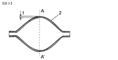
- FIG. 1 is a schematic view showing a cross-sectional view in the major axis direction of the distal end portion of the ablation catheter with a balloon according to the first embodiment of the present invention.
- the 1 includes a double tube shaft 9 having an outer tube shaft 3 and an inner tube shaft 6, and a balloon 2.
- the balloon 2 has a spherical shape, and the outer cylinder shaft 6, which is a flexible tube, is connected to the distal end of the outer cylinder shaft 6 at the opening on the proximal end side of the balloon 2. Further, the inner tube 6 that is a flexible tube passes through the inside of the balloon 2 and is connected to the opening portion on the distal end side of the balloon 2. Thereby, the balloon 2 is sealed.
- An electrode 5 is provided on the inner cylindrical shaft 6 inside the balloon 2, and the electrode 5 is connected to a high-frequency power source (not shown) by an electric wire 7. Moreover, the temperature sensor electric wire 8 is connected to the electrode 5, and the electrode 5 also has a role as a temperature sensor.
- the electrode 5 is disposed near the center of the balloon in the long axis direction so that the temperature inside the balloon 2 can be measured.
- FIG. 2 is a schematic view showing a cross-sectional view in the longitudinal direction of the outer tube shaft of the ablation catheter with a balloon according to the first embodiment of the present invention.
- the thick portion of the outer cylindrical shaft 3 in FIG. 1 is composed of a three-layer thickness portion from the inner surface of the inner tube 9 to the outer surface of the outer tube 10 with the reinforcing wire 4 interposed therebetween.
- the distance L indicates the distance from the outermost surface on the outer layer side of the reinforcing layer 4 to the surface of the outer tube 10.
- the reinforcing wire 4 is arranged so that the length L is longer than the film thickness t, so that when a high frequency is emitted from a counter electrode (not shown) toward the balloon, the balloon is more than the reinforcing wire 4. Since the high frequency easily flows to the electrode 5 inside 2, the heating of the reinforcing wire 4 can be prevented.
- the material of the balloon 2 may be any material as long as it is a material used for a medical catheter. However, in order to improve the adhesion to the affected tissue, such as rubber such as polyurethane, synthetic rubber or natural rubber. It is preferable to use a stretchable material.
- the film thickness of the balloon 2 is preferably 20 to 150 microns in order to improve adhesion to the affected tissue, but more preferably 20 to 100 microns.
- the appropriate outer diameter of the balloon 2 varies depending on the affected part to which the technique is applied. For example, when used for the treatment of arrhythmia, the outer diameter is preferably 20 to 40 mm.
- the shape of the balloon 2 is preferably a spherical shape, but may be a conical shape with a tapered tip, and is not limited to these shapes.
- any material may be used as long as it is a material used for a medical catheter.
- a polyamide resin such as nylon 11 or nylon 12 or a polyamide elastomer, Examples thereof include polyolefins such as polypropylene and polyethylene, polyesters such as polyethylene terephthalate, flexible polymer materials such as polyurethane and vinyl chloride, and one or more of these can be used in combination.
- a contrast material such as barium sulfate or bismuth carbonate may be included in the material of the outer cylinder shaft 3 and the inner cylinder shaft 6.
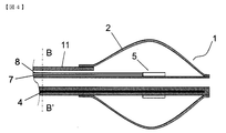
- FIG. 4 is a cross-sectional view in the major axis direction of an ablation catheter with a balloon according to the second embodiment of the present invention.
- a multi-lumen shaft 11 is used in place of the double tube shaft.
- the reinforcing wire 4 is internally provided in the thick portion of the multi-lumen shaft 12 in a straight line with respect to the long axis direction of the multi-lumen shaft 11.
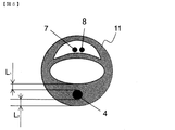
- FIG. 5 is a cross-sectional view taken along the plane BB ′, which is a direction perpendicular to the long axis direction of the multi-lumen shaft 12 shown in FIG.
- the thick portion is a portion having a thickness from the lumen as a lumen to the outer layer surface of the shaft with the reinforcing wire 4 interposed therebetween.
- the distance L includes two shortest distances L 1 from the surface of the reinforcing wire 4 to the inner lumen surface of the multi-lumen shaft 12 and two shortest distances L 2 from the surface of the reinforcing wire 4 to the outer surface of the multi-lumen shaft 12.
- the cross-sectional shape of the reinforcing wire 4 is not particularly limited, but when the reinforcing wire 4 is braided by making the cross-sectional shape a flat wire, the contact area of each reinforcing wire 4 is improved and the frictional force is increased. This can increase the elongation of the catheter shaft.
- the temperature sensor wire 8 needs to be made of a different metal from the wire 7 in order to measure temperature.
- the wire 7 is made of copper and the temperature sensor wire 8 is made of a constantan wire. It is not something.
- the electric wire 7 serves as the role of the electric wire for high frequency electricity supply, and the role of the electric wire for forming a thermocouple.
- the electric wire for high-frequency energization and the electric wire for thermocouple may be separated.
- the balloon 2 is a spherical balloon having a thickness of 40 microns at the thinnest portion and an outer diameter of the balloon of 25 mm.
- the length of the neck portion at the base end of the balloon is 10 mm and the outer diameter is 3. It was made by blow molding using a urethane material with an inner diameter of 6 mm, an inner diameter of 3.1 mm, a length of the neck portion at the tip of the balloon of 10 mm, an outer diameter of 2 mm, and an inner diameter of 1.6 mm.
- a reinforcing wire 4 of a SUS plate material having a thickness of 60 microns and a width of 190 microns is formed along the major axis direction of the inner layer tube 9 in a knitted pattern.
- the outer layer tube 10 was formed by covering the polyurethane material so that the outer diameter was 3.1 mm, and the outer cylinder shaft 3 having a three-layer structure was manufactured.
- the inner cylinder shaft 6 was made of nylon so as to be a single lumen shaft having an inner diameter of 1.2 mm and an outer diameter of 1.6 mm.
- the electrode 5 is a copper wire with a silver plating of 30 microns in diameter, starting at a position 20 mm from the distal end of the inner cylindrical shaft 6 and 10 mm toward the proximal end in the longitudinal direction of the major axis. It was wound on the tube shaft 6 in a coil shape.
- the inner cylinder shaft assembly produced by combining the inner cylinder shaft 6, the electrode 5, the electric wire 7, and the temperature sensor electric wire 8 is projected 35 mm from the outer cylinder shaft 3 to the distal end side in the long axis direction.
- the outer cylindrical shaft 3 and the neck portion on the proximal end side in the long axis direction of the balloon 2 and the neck portion on the distal end side in the long axis direction of the balloon 2 and the inner cylindrical shaft 6 are thermally bonded to each other.
- An ablation catheter 1 with a balloon was produced.
- the obtained outer cylindrical shaft 3 has an inner diameter of 2.5 mm, an outer diameter of 3.0 mm, a wall thickness of 250 microns, and a length of 900 mm.
- the shortest distance from the surface of the reinforcing wire 4 to the surface of the outer cylindrical shaft 3 is 30.
- a single lumen catheter shaft of micron size was prepared. Other configurations were the same as those in Production Example 1. (Elongation test)
- the ablation catheter with a balloon prepared in Example 1 and Comparative Example 1 was immersed in warm water at 37 ° C. for 2 hours, and then the distal ends of both outer cylindrical shafts in the major axis direction were held by hand, A weight of 7 kg was applied to the rear end in the long axis direction, and a sufficient time was applied for weighting, and the extension of the outer cylinder shaft was compared.
- the elongation of the outer cylinder shaft of the ablation catheter with balloon of Production Example 1 was changed from 900 mm to 901 mm, and the outer cylinder shaft 3 did not cover the electrode 5, so that it was usable as an ablation catheter with balloon. It was. Further, the elongation of the outer cylinder shaft of the ablation catheter with balloon of Comparative Example 1 is 900 mm to 910 mm, and the outer cylinder shaft 3 covers most of the electrode 5, which is difficult to use as an ablation catheter with balloon. It became.
- Example 1 In order to compare the difference in heat generation between Example 1 and Comparative Example 2, high-frequency power was supplied to the ablation catheter with a balloon created in Example 1 and Comparative Example 2 to compare the surface temperature of the catheter shaft. .
- FIG. 6 shows a schematic diagram of the catheter shaft exothermic test system.
- a counter electrode 14 connected to a high-frequency power source 13 is installed in a water tank 12 filled with 0.9% physiological saline at 37 ° C., and the ablation catheters of Example 1 and Comparative Example 2 are immersed in the water tank 12.
- the temperature sensor wire 8 was connected to the high frequency power source 14.
- a thermocouple 15 was affixed to the surface near the balloon of the outer tube 3 of the ablation catheter 1 with a balloon, and the temperature when a high frequency current was applied was measured with a temperature measuring device 16.
- a solution obtained by diluting a contrast medium (Ioxaglic acid injection solution: trade name Hexabrix 320) to 50% with physiological saline is injected into the balloon 2 to make the balloon 2 of Example 1 and Comparative Example 2 have an outer diameter of 25 mm. Inflated.
- a contrast medium Ioxaglic acid injection solution: trade name Hexabrix 320
- thermocouple was installed at a position 15 mm from the tip of the outer cylinder shaft 3.
- Example 1 When the frequency of the high frequency power source was set to 1.8 Mhz, the set temperature in the balloon 2 was set to 70 ° C., and the high frequency was energized for 5 minutes, in Example 1, the measured surface temperature of the outer cylindrical shaft 3 was 39 ° C. In contrast, in Comparative Example 2, the measured surface temperature of the outer cylindrical shaft 3 was 51 ° C.
- the present invention can be used as an ablation catheter with balloon and an ablation catheter system with balloon for cauterizing a target lesion site.
Landscapes
- Health & Medical Sciences (AREA)
- Life Sciences & Earth Sciences (AREA)
- Engineering & Computer Science (AREA)
- Surgery (AREA)
- Heart & Thoracic Surgery (AREA)
- Veterinary Medicine (AREA)
- Public Health (AREA)
- General Health & Medical Sciences (AREA)
- Animal Behavior & Ethology (AREA)
- Biomedical Technology (AREA)
- Molecular Biology (AREA)
- Medical Informatics (AREA)
- Otolaryngology (AREA)
- Nuclear Medicine, Radiotherapy & Molecular Imaging (AREA)
- Plasma & Fusion (AREA)
- Physics & Mathematics (AREA)
- Cardiology (AREA)
- Surgical Instruments (AREA)
- Media Introduction/Drainage Providing Device (AREA)
- Biophysics (AREA)
- Pulmonology (AREA)
- Anesthesiology (AREA)
- Hematology (AREA)
- Electrotherapy Devices (AREA)
Abstract
Description
(1) 肉厚部に補強線が内装されたカテーテルシャフトと、上記カテーテルシャフトの端部に付設されたバルーンと、上記バルーンの内部に配設された高周波通電用電極と、を備え、上記補強線の表面から上記カテーテルシャフトの表面までの最短距離をLとし、上記バルーンの最も薄い部分の膜厚をtとした場合に、L>tとなる、バルーン付きアブレーションカテーテル。
(2) 上記バルーンの膜厚は、20~150μmである、上記(1)記載のバルーン付きアブレーションカテーテル。
(3) 上記補強線は、金属線である、上記(1)又は(2)記載のバルーン付きアブレーションカテーテル。
(4) 上記補強線は、編組状に内装されている、上記(1)~(3)のいずれかに記載のバルーン付きアブレーションカテーテル。
(5) 上記補強線は、上記カテーテルシャフトの長軸方向に対して直線状に内装されている上記(1)~(3)のいずれかに記載のバルーン付きアブレーションカテーテル。
(6) 上記補強線は、上記カテーテルシャフトの末端側の先端から露出しないように内装されている、上記(1)~(5)のいずれかに記載のバルーン付きアブレーションカテーテル。
(7) 上記(1)~(6)のいずれかに記載のバルーン付きアブレーションカテーテルと、上記バルーン内の高周波通電用電極に高周波を送る対電極と、上記対電極に高周波電力を供給する高周波電源と、を備える、バルーン付きアブレーションカテーテルシステム。
また、「補強線」とは、カテーテルシャフト内で、カテーテルシャフトの剛性を補強するために内装されている線である。
バルーン2を、最も薄い部分の膜厚が40ミクロン、バルーンの外径が25mmの球形状のバルーンとし、バルーンの基端部のネック部分の長軸方向の長さを10mm、外径を3.6mm、内径を3.1mm、バルーンの先端部のネック部分の長軸方向の長さを10mm、外径を2mm、内径を1.6mmとして、ウレタン材料を用いてブロー成型により作製した。
(比較例1)
(比較例2)
(伸び試験)
(発熱試験)
37℃の0.9%生理食塩水で満たした水槽12に高周波電源13に接続された対極板14を設置し、実施例1及び比較例2のアブレーションカテーテルを水槽12に浸漬させ、電線7と温度センサ用電線8を高周波電源14に接続した。バルーン付きアブレーションカテーテル1の外筒シャフト3のバルーン付近の表面に、熱電対15を貼り付け、温度測定器16にて、高周波通電した際の温度を測定した。
Claims (7)
- 肉厚部に補強線が内装されたカテーテルシャフトと、
前記カテーテルシャフトの端部に付設されたバルーンと、
前記バルーンの内部に配設された高周波通電用電極と、
を備え、
前記補強線の表面から前記カテーテルシャフトの表面までの最短距離をLとし、前記バルーンの最も薄い部分の膜厚をtとした場合に、L>tとなる、バルーン付きアブレーションカテーテル。 - 前記バルーンの膜厚は、20~150μmである、請求項1記載のバルーン付きアブレーションカテーテル。
- 前記補強線は、金属線である、請求項1又は2記載のバルーン付きアブレーションカテーテル。
- 前記補強線は、編組状に内装されている、請求項1~3のいずれか一項記載のバルーン付きアブレーションカテーテル。
- 前記補強線は、前記カテーテルシャフトの長軸方向に対して直線状に内装されている請求項1~3のいずれか一項記載のバルーン付きアブレーションカテーテル。
- 前記補強線は、前記カテーテルシャフトの末端側の先端から露出しないように内装されている、請求項1~5のいずれか一項記載のバルーン付きアブレーションカテーテル。
- 請求項1~6のいずれか一項記載のバルーン付きアブレーションカテーテルと、
前記バルーン内の高周波通電用電極に高周波を送る対電極と、
前記対電極に高周波電力を供給する高周波電源と、
を備える、バルーン付きアブレーションカテーテルシステム。
Priority Applications (8)
| Application Number | Priority Date | Filing Date | Title |
|---|---|---|---|
| CN201480018200.8A CN105050520B (zh) | 2013-03-28 | 2014-03-28 | 带气囊的消融导管以及带气囊的消融导管系统 |
| CA2901243A CA2901243C (en) | 2013-03-28 | 2014-03-28 | Balloon ablation catheter and balloon ablation catheter system |
| US14/777,634 US11172983B2 (en) | 2013-03-28 | 2014-03-28 | Balloon ablation catheter and balloon ablation catheter system |
| ES14775630T ES2698616T3 (es) | 2013-03-28 | 2014-03-28 | Catéter de ablación con globo y sistema de catéter de ablación con globo |
| EP14775630.8A EP2979655B1 (en) | 2013-03-28 | 2014-03-28 | Balloon ablation catheter and balloon ablation catheter system |
| KR1020157024967A KR102178429B1 (ko) | 2013-03-28 | 2014-03-28 | 벌룬이 부착된 어블레이션 카테터 및 벌룬이 부착된 어블레이션 카테터 시스템 |
| DK14775630.8T DK2979655T3 (en) | 2013-03-28 | 2014-03-28 | Balloon ablation catheter and balloon ablation catheter system |
| JP2014514956A JP6287833B2 (ja) | 2013-03-28 | 2014-03-28 | バルーン付きアブレーションカテーテル及びバルーン付きアブレーションカテーテルシステム |
Applications Claiming Priority (2)
| Application Number | Priority Date | Filing Date | Title |
|---|---|---|---|
| JP2013-068479 | 2013-03-28 | ||
| JP2013068479 | 2013-03-28 |
Publications (1)
| Publication Number | Publication Date |
|---|---|
| WO2014157633A1 true WO2014157633A1 (ja) | 2014-10-02 |
Family
ID=51624589
Family Applications (1)
| Application Number | Title | Priority Date | Filing Date |
|---|---|---|---|
| PCT/JP2014/059181 WO2014157633A1 (ja) | 2013-03-28 | 2014-03-28 | バルーン付きアブレーションカテーテル及びバルーン付きアブレーションカテーテルシステム |
Country Status (10)
| Country | Link |
|---|---|
| US (1) | US11172983B2 (ja) |
| EP (1) | EP2979655B1 (ja) |
| JP (1) | JP6287833B2 (ja) |
| KR (1) | KR102178429B1 (ja) |
| CN (1) | CN105050520B (ja) |
| CA (1) | CA2901243C (ja) |
| DK (1) | DK2979655T3 (ja) |
| ES (1) | ES2698616T3 (ja) |
| TW (1) | TWI598071B (ja) |
| WO (1) | WO2014157633A1 (ja) |
Families Citing this family (7)
| Publication number | Priority date | Publication date | Assignee | Title |
|---|---|---|---|---|
| EP3397149A4 (en) | 2015-12-30 | 2019-08-14 | Schuler Scientific Solutions, LLC | CARTOGRAPHY AND TREATMENT OF TISSUE |
| WO2017146465A1 (ko) * | 2016-02-22 | 2017-08-31 | 재단법인 아산사회복지재단 | 전기도금을 이용한 소작용 카테터 선단부의 제조 방법 |
| WO2022077313A1 (zh) * | 2020-10-15 | 2022-04-21 | 山前(珠海)医疗科技有限公司 | 一种带加热功能的冷冻球囊导管 |
| US11484327B2 (en) * | 2021-02-26 | 2022-11-01 | Fastwave Medical Inc. | Intravascular lithotripsy |
| US11911056B2 (en) | 2021-02-26 | 2024-02-27 | Fastwave Medical Inc. | Intravascular lithotripsy |
| US11944331B2 (en) | 2021-02-26 | 2024-04-02 | Fastwave Medical Inc. | Intravascular lithotripsy |
| WO2023235665A1 (en) | 2022-06-01 | 2023-12-07 | Fastwave Medical Inc. | Intravascular lithotripsy |
Citations (6)
| Publication number | Priority date | Publication date | Assignee | Title |
|---|---|---|---|---|
| JP2000225195A (ja) | 1999-02-05 | 2000-08-15 | Hitachi Cable Ltd | カテーテルチューブおよびその製造方法 |
| JP2002078809A (ja) | 2000-09-07 | 2002-03-19 | Shutaro Satake | 肺静脈電気的隔離用バルーンカテーテル |
| WO2004017850A1 (ja) * | 2002-08-20 | 2004-03-04 | Toray Industries,Inc. | 心臓不整脈治療用カテーテル |
| JP2005058509A (ja) * | 2003-08-13 | 2005-03-10 | Toray Ind Inc | バルーン付きアブレーションカテーテル |
| WO2007052341A1 (ja) * | 2005-11-01 | 2007-05-10 | Japan Electel Inc. | バルーンカテーテルシステム |
| WO2010113914A1 (ja) * | 2009-03-31 | 2010-10-07 | 東レ株式会社 | バルーン付きアブレーションカテーテル用シャフト |
Family Cites Families (9)
| Publication number | Priority date | Publication date | Assignee | Title |
|---|---|---|---|---|
| US5807395A (en) * | 1993-08-27 | 1998-09-15 | Medtronic, Inc. | Method and apparatus for RF ablation and hyperthermia |
| US6053913A (en) * | 1998-09-10 | 2000-04-25 | Tu; Lily Chen | Rapid exchange stented balloon catheter having ablation capabilities |
| CN2462972Y (zh) * | 2001-02-16 | 2001-12-05 | 重庆医科大学 | 循环式水囊超声消融导管 |
| EP1585574A4 (en) * | 2002-12-20 | 2006-04-26 | Cardiac Inv S Unltd Inc | DEVICE AND METHOD FOR IMPLANTING LEFT-VATRICULAR PIPE MACHINE IN KORONARSINUS |
| JP4067976B2 (ja) * | 2003-01-24 | 2008-03-26 | 有限会社日本エレクテル | 高周波加温バルーンカテーテル |
| US8185194B2 (en) * | 2003-02-21 | 2012-05-22 | Dtherapeutics, Llc | Systems and methods for determining phasic cardiac cycle measurements |
| DE202004021953U1 (de) * | 2003-09-12 | 2013-06-19 | Vessix Vascular, Inc. | Auswählbare exzentrische Remodellierung und/oder Ablation von atherosklerotischem Material |
| US9572583B2 (en) * | 2007-11-21 | 2017-02-21 | St. Jude Medical, Atrial Fibrillation Division, Inc. | Methods and systems for occluding vessels during cardiac ablation |
| US20120150107A1 (en) * | 2010-12-14 | 2012-06-14 | Boston Scientific Scimed, Inc. | Balloon catheter shafts and methods of manufacturing |
-
2014
- 2014-03-20 TW TW103110423A patent/TWI598071B/zh active
- 2014-03-28 EP EP14775630.8A patent/EP2979655B1/en active Active
- 2014-03-28 CN CN201480018200.8A patent/CN105050520B/zh active Active
- 2014-03-28 US US14/777,634 patent/US11172983B2/en active Active
- 2014-03-28 ES ES14775630T patent/ES2698616T3/es active Active
- 2014-03-28 DK DK14775630.8T patent/DK2979655T3/en active
- 2014-03-28 JP JP2014514956A patent/JP6287833B2/ja active Active
- 2014-03-28 KR KR1020157024967A patent/KR102178429B1/ko active IP Right Grant
- 2014-03-28 WO PCT/JP2014/059181 patent/WO2014157633A1/ja active Application Filing
- 2014-03-28 CA CA2901243A patent/CA2901243C/en active Active
Patent Citations (6)
| Publication number | Priority date | Publication date | Assignee | Title |
|---|---|---|---|---|
| JP2000225195A (ja) | 1999-02-05 | 2000-08-15 | Hitachi Cable Ltd | カテーテルチューブおよびその製造方法 |
| JP2002078809A (ja) | 2000-09-07 | 2002-03-19 | Shutaro Satake | 肺静脈電気的隔離用バルーンカテーテル |
| WO2004017850A1 (ja) * | 2002-08-20 | 2004-03-04 | Toray Industries,Inc. | 心臓不整脈治療用カテーテル |
| JP2005058509A (ja) * | 2003-08-13 | 2005-03-10 | Toray Ind Inc | バルーン付きアブレーションカテーテル |
| WO2007052341A1 (ja) * | 2005-11-01 | 2007-05-10 | Japan Electel Inc. | バルーンカテーテルシステム |
| WO2010113914A1 (ja) * | 2009-03-31 | 2010-10-07 | 東レ株式会社 | バルーン付きアブレーションカテーテル用シャフト |
Non-Patent Citations (1)
| Title |
|---|
| See also references of EP2979655A4 * |
Also Published As
| Publication number | Publication date |
|---|---|
| TWI598071B (zh) | 2017-09-11 |
| JPWO2014157633A1 (ja) | 2017-02-16 |
| EP2979655A1 (en) | 2016-02-03 |
| EP2979655B1 (en) | 2018-11-07 |
| KR20150135264A (ko) | 2015-12-02 |
| ES2698616T3 (es) | 2019-02-05 |
| EP2979655A4 (en) | 2016-11-09 |
| CA2901243C (en) | 2018-02-06 |
| CN105050520B (zh) | 2017-06-27 |
| JP6287833B2 (ja) | 2018-03-07 |
| CN105050520A (zh) | 2015-11-11 |
| CA2901243A1 (en) | 2014-10-02 |
| TW201446213A (zh) | 2014-12-16 |
| DK2979655T3 (en) | 2019-03-04 |
| US11172983B2 (en) | 2021-11-16 |
| KR102178429B1 (ko) | 2020-11-13 |
| US20160287323A1 (en) | 2016-10-06 |
Similar Documents
| Publication | Publication Date | Title |
|---|---|---|
| JP6287833B2 (ja) | バルーン付きアブレーションカテーテル及びバルーン付きアブレーションカテーテルシステム | |
| JP5853426B2 (ja) | バルーン付きアブレーションカテーテル | |
| JP4988044B2 (ja) | バルーンカテーテルシステム | |
| KR101347141B1 (ko) | 벌룬이 부착된 어블레이션 카테터용 샤프트 | |
| US6669692B1 (en) | Ablation catheter with cooled linear electrode | |
| EP2073738B1 (en) | Ablation catheter apparatus with one or more electrodes | |
| KR101319899B1 (ko) | 벌룬이 부착된 어블레이션 카테터 및 벌룬이 부착된 어블레이션 카테터 시스템 | |
| AU2012282473B2 (en) | Ablation applicator with a matrix filled with particles | |
| TWI526192B (zh) | 附有氣球之電燒導管系統 | |
| JPH09140801A (ja) | 電極カテーテル | |
| JP2021010455A (ja) | バルーンカテーテルおよびその作動方法 | |
| JP4140483B2 (ja) | バルーン付きアブレーションカテーテル | |
| US20220304748A1 (en) | Catheter device, catheter body, and catheter | |
| CN216317941U (zh) | 球囊形脉冲电场消融装置 | |
| US20220304625A1 (en) | Catheter device and catheter | |
| JP2006263045A (ja) | カテーテルおよびカテーテル操縦機構 | |
| JP2022124298A (ja) | 体組織穿孔用デバイス | |
| JP2021010457A (ja) | バルーンカテーテルおよびその作動方法 | |
| JP2022105952A (ja) | 中隔穿刺デバイス | |
| JP2021146031A (ja) | バルーンカテーテル | |
| CN113952020A (zh) | 球囊形脉冲电场消融装置 | |
| JP2010264043A (ja) | バルーン付きアブレーションカテーテル用の操作用ハンドル | |
| JPH0994254A (ja) | アブレーションカテーテル |
Legal Events
| Date | Code | Title | Description |
|---|---|---|---|
| WWE | Wipo information: entry into national phase |
Ref document number: 201480018200.8 Country of ref document: CN |
|
| ENP | Entry into the national phase |
Ref document number: 2014514956 Country of ref document: JP Kind code of ref document: A |
|
| 121 | Ep: the epo has been informed by wipo that ep was designated in this application |
Ref document number: 14775630 Country of ref document: EP Kind code of ref document: A1 |
|
| ENP | Entry into the national phase |
Ref document number: 2901243 Country of ref document: CA |
|
| WWE | Wipo information: entry into national phase |
Ref document number: 2014775630 Country of ref document: EP |
|
| ENP | Entry into the national phase |
Ref document number: 20157024967 Country of ref document: KR Kind code of ref document: A |
|
| WWE | Wipo information: entry into national phase |
Ref document number: 14777634 Country of ref document: US |
|
| NENP | Non-entry into the national phase |
Ref country code: DE |