WO2014157125A1 - ナトリウム二次電池 - Google Patents
ナトリウム二次電池 Download PDFInfo
- Publication number
- WO2014157125A1 WO2014157125A1 PCT/JP2014/058155 JP2014058155W WO2014157125A1 WO 2014157125 A1 WO2014157125 A1 WO 2014157125A1 JP 2014058155 W JP2014058155 W JP 2014058155W WO 2014157125 A1 WO2014157125 A1 WO 2014157125A1
- Authority
- WO
- WIPO (PCT)
- Prior art keywords
- active material
- negative electrode
- electrode active
- secondary battery
- sodium
- Prior art date
- Legal status (The legal status is an assumption and is not a legal conclusion. Google has not performed a legal analysis and makes no representation as to the accuracy of the status listed.)
- Ceased
Links
Images
Classifications
-
- H—ELECTRICITY
- H01—ELECTRIC ELEMENTS
- H01M—PROCESSES OR MEANS, e.g. BATTERIES, FOR THE DIRECT CONVERSION OF CHEMICAL ENERGY INTO ELECTRICAL ENERGY
- H01M4/00—Electrodes
- H01M4/02—Electrodes composed of, or comprising, active material
- H01M4/13—Electrodes for accumulators with non-aqueous electrolyte, e.g. for lithium-accumulators; Processes of manufacture thereof
-
- H—ELECTRICITY
- H01—ELECTRIC ELEMENTS
- H01M—PROCESSES OR MEANS, e.g. BATTERIES, FOR THE DIRECT CONVERSION OF CHEMICAL ENERGY INTO ELECTRICAL ENERGY
- H01M10/00—Secondary cells; Manufacture thereof
- H01M10/05—Accumulators with non-aqueous electrolyte
- H01M10/054—Accumulators with insertion or intercalation of metals other than lithium, e.g. with magnesium or aluminium
-
- H—ELECTRICITY
- H01—ELECTRIC ELEMENTS
- H01M—PROCESSES OR MEANS, e.g. BATTERIES, FOR THE DIRECT CONVERSION OF CHEMICAL ENERGY INTO ELECTRICAL ENERGY
- H01M10/00—Secondary cells; Manufacture thereof
- H01M10/05—Accumulators with non-aqueous electrolyte
- H01M10/056—Accumulators with non-aqueous electrolyte characterised by the materials used as electrolytes, e.g. mixed inorganic/organic electrolytes
- H01M10/0561—Accumulators with non-aqueous electrolyte characterised by the materials used as electrolytes, e.g. mixed inorganic/organic electrolytes the electrolyte being constituted of inorganic materials only
- H01M10/0562—Solid materials
-
- H—ELECTRICITY
- H01—ELECTRIC ELEMENTS
- H01M—PROCESSES OR MEANS, e.g. BATTERIES, FOR THE DIRECT CONVERSION OF CHEMICAL ENERGY INTO ELECTRICAL ENERGY
- H01M10/00—Secondary cells; Manufacture thereof
- H01M10/05—Accumulators with non-aqueous electrolyte
- H01M10/056—Accumulators with non-aqueous electrolyte characterised by the materials used as electrolytes, e.g. mixed inorganic/organic electrolytes
- H01M10/0564—Accumulators with non-aqueous electrolyte characterised by the materials used as electrolytes, e.g. mixed inorganic/organic electrolytes the electrolyte being constituted of organic materials only
- H01M10/0565—Polymeric materials, e.g. gel-type or solid-type
-
- H—ELECTRICITY
- H01—ELECTRIC ELEMENTS
- H01M—PROCESSES OR MEANS, e.g. BATTERIES, FOR THE DIRECT CONVERSION OF CHEMICAL ENERGY INTO ELECTRICAL ENERGY
- H01M10/00—Secondary cells; Manufacture thereof
- H01M10/05—Accumulators with non-aqueous electrolyte
- H01M10/058—Construction or manufacture
- H01M10/0585—Construction or manufacture of accumulators having only flat construction elements, i.e. flat positive electrodes, flat negative electrodes and flat separators
-
- H—ELECTRICITY
- H01—ELECTRIC ELEMENTS
- H01M—PROCESSES OR MEANS, e.g. BATTERIES, FOR THE DIRECT CONVERSION OF CHEMICAL ENERGY INTO ELECTRICAL ENERGY
- H01M4/00—Electrodes
- H01M4/02—Electrodes composed of, or comprising, active material
- H01M4/64—Carriers or collectors
- H01M4/66—Selection of materials
-
- Y—GENERAL TAGGING OF NEW TECHNOLOGICAL DEVELOPMENTS; GENERAL TAGGING OF CROSS-SECTIONAL TECHNOLOGIES SPANNING OVER SEVERAL SECTIONS OF THE IPC; TECHNICAL SUBJECTS COVERED BY FORMER USPC CROSS-REFERENCE ART COLLECTIONS [XRACs] AND DIGESTS
- Y02—TECHNOLOGIES OR APPLICATIONS FOR MITIGATION OR ADAPTATION AGAINST CLIMATE CHANGE
- Y02E—REDUCTION OF GREENHOUSE GAS [GHG] EMISSIONS, RELATED TO ENERGY GENERATION, TRANSMISSION OR DISTRIBUTION
- Y02E60/00—Enabling technologies; Technologies with a potential or indirect contribution to GHG emissions mitigation
- Y02E60/10—Energy storage using batteries
-
- Y—GENERAL TAGGING OF NEW TECHNOLOGICAL DEVELOPMENTS; GENERAL TAGGING OF CROSS-SECTIONAL TECHNOLOGIES SPANNING OVER SEVERAL SECTIONS OF THE IPC; TECHNICAL SUBJECTS COVERED BY FORMER USPC CROSS-REFERENCE ART COLLECTIONS [XRACs] AND DIGESTS
- Y02—TECHNOLOGIES OR APPLICATIONS FOR MITIGATION OR ADAPTATION AGAINST CLIMATE CHANGE
- Y02P—CLIMATE CHANGE MITIGATION TECHNOLOGIES IN THE PRODUCTION OR PROCESSING OF GOODS
- Y02P70/00—Climate change mitigation technologies in the production process for final industrial or consumer products
- Y02P70/50—Manufacturing or production processes characterised by the final manufactured product
Definitions
- the present invention relates to a sodium secondary battery.
- a conventional sodium secondary battery has a structural unit in which a layer containing a positive electrode active material is laminated on both sides of a current collector, and a layer containing a negative electrode active material on both sides of a current collector. It was a sodium secondary battery having a structure in which a separator was laminated between structural units (Japanese Patent Laid-Open No. 2010-225525).
- the above-mentioned sodium secondary battery has a complicated battery structure because all current collectors require current collecting terminals for extracting current to the outside.
- the present invention has been made in view of such circumstances, and an object thereof is to provide a sodium secondary battery having a simple battery structure.
- the inventor has conducted extensive studies to solve the above-described problems, and has reached the present invention.
- the present invention includes a layer containing a positive electrode active material that can be doped and dedoped with sodium ions, a layer containing a negative electrode active material that can be doped and dedoped with sodium ions, an electrolyte capable of conducting sodium ions, and a current collector.
- a sodium secondary battery having at least one current collector, wherein the electrolyte is a solid electrolyte.
- a sodium secondary battery having a simple battery structure can be provided.
- a sodium secondary battery is extremely useful industrially because it can be made of an inexpensive material.
- the sodium secondary battery of this embodiment includes a layer containing a positive electrode active material that can be doped and dedoped with sodium ions, a layer containing a negative electrode active material that can be doped and dedoped with sodium ions, an electrolyte capable of conducting sodium ions,
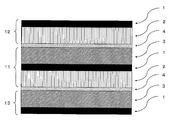
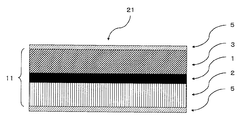
- a structure in which a layer containing the positive electrode active material is laminated on one surface of a current collector and a layer containing the negative electrode active material is laminated on the other surface is called a bipolar electrode.
- a bipolar electrode A structure in which a layer containing the positive electrode active material is laminated on one surface of a current collector and a layer containing the negative electrode active material is laminated on the other surface.
- the electrolyte of the sodium secondary battery of this embodiment is an electrolyte that is solid at room temperature and can conduct sodium ions.
- the solid electrolyte has too low ionic conductivity and it has been difficult to use as a real battery.
- sufficient ionic conductivity is obtained.
- an ionic short circuit does not occur on the back and front of the current collector, so that the insulating portions on the back and front of the current collector are not necessary.
- the solid electrolyte since the solid electrolyte has higher flame retardancy than a liquid electrolyte at room temperature, a sodium secondary battery with higher safety can be provided.
- the solid electrolyte may be an organic solid electrolyte, an inorganic solid electrolyte, or a mixture thereof. From the viewpoint of improving the interfacial bonding between the positive electrode active material and the solid electrolyte and the interfacial bonding between the negative electrode active material and the solid electrolyte, the organic solid electrolyte is preferable.
- the organic solid electrolyte is more preferably a polymer containing sodium ions.
- Organic solid electrolyte is obtained, for example, by mixing a polymerizable monomer, a sodium salt, and, if necessary, a polymerization initiator and polymerizing the mixture.
- a polymerizable monomer and, if necessary, a polymerization initiator may be mixed and polymerized, and then the obtained polymer and sodium salt may be dissolved in a solvent.
- the polymerization method include polymerization methods such as thermal polymerization, photopolymerization, and radiation polymerization.
- a monomer containing one or more structural units selected from the group consisting of a structural unit represented by the following formula (1) and a structural unit represented by the following formula (2) can be used. . —CH 2 —CH 2 —O— (1) —CH 2 —CHCH 3 —O— (2)
- Examples of the monomer containing one or more structural units selected from the group consisting of the structural unit represented by the above formula (1) and the structural unit represented by the above formula (2) include NK ester A manufactured by Shin-Nakamura Chemical Co., Ltd. -200, A-400, A-600, APG-100, APG-200, APG-400, APG-700, A-GLY-9E, A-GLY-20E, A-TMMT, AD-TMP, ATM-35E , A-TMMT, A9550, A-DPH.
- sodium salt examples include NaPF 6 , NaBF 4 , NaClO 4 , NaCF 3 CONSO 2 CF 3 , NaN (SO 2 C 2 F 5 ) 2 , NaN (SO 2 CF 3 ) 2 , NaCF 3 SO 3 , NaC ( CF 3 SO 2) 3 and the like.
- Polymerization initiator examples include azo polymerization initiators and peroxide polymerization initiators.
- azo polymerization initiator examples include 2,2′-azobis-isobutyronitrile, 2,2′-azobis-2-methylbutyronitrile, and 2,2′-azobis-2,4-dimethylvaleronitrile. It is done.
- peroxide-based polymerization initiators isobutyl peroxide, lauroyl peroxide, benzoyl peroxide, m-toluoyl peroxide, t-butylperoxy-2-ethylhexanoate, t-butylperoxybivalate- Butyloxyneodecanate, diisopropylperoxydicarbonate, diethoxyperoxydicarbonate, bis- (4-tert-butylcyclohexyl) peroxydicarbonate, dimethoxyisopropylperoxydicarbonate, dicyclohexylperoxydicarbonate and 3,3 , 5-trimethylhexanoyl peroxide.
- a commercially available product can be used as the inorganic solid electrolyte, and examples thereof include a NASICON type solid electrolyte and a sulfide type solid electrolyte.
- the composition of the NASICON solid electrolyte preferably contains Na 1 + x Zr 2 Si x O 12 (x is 0 or more and 3 or less).
- the composition of the sulfide-based solid electrolyte preferably includes, for example, Na 2 S and P 2 S 5 .
- ⁇ Layer containing positive electrode active material> As the positive electrode active material of the sodium secondary battery of this embodiment, a material capable of doping and dedoping sodium can be used.
- the positive electrode active material examples include sodium metal, a sodium alloy, and a sodium inorganic compound that can be doped and dedoped with sodium ions.
- the layer containing the positive electrode active material is, for example, one in which an electrode mixture containing a Na compound, a binder, a conductive agent and the like is supported on a current collector, and is preferably in a sheet form.
- a method for producing a positive electrode active material using a Na compound (1) A method in which an electrode mixture formed by adding a solvent to a Na compound, a binder, a conductive agent and the like is applied to a current collector by a doctor blade method or the like, or dipped and dried, (2) A sheet obtained by adding a solvent to the Na compound, binder, conductive agent, etc., kneading, shaping, and drying is bonded to the current collector surface via a conductive adhesive, and then pressed and heat-treated. Method, (3) After forming a mixture of Na compound, binder, conductive agent and liquid lubricant on the current collector, the liquid lubricant is removed, and then the obtained sheet-like molded product is uniaxial or multiaxial. And a method of stretching in the direction.
- the thickness is preferably about 5 to 500 ⁇ m.
- M 1 is one or more transition metal elements, 0 ⁇ a ⁇ 1
- Oxides represented by Na b M 2 c Si 12 O 30 such as Na 6 Fe 2 Si 12 O 30 and Na 2 Fe 5 Si 12 O 30
- M 2 is one or more transition metal elements, 2 ⁇ b ⁇ 6, 2 ⁇ c ⁇ 5
- M 4 is at least one element selected from the group consisting of transition metal elements
- a compound containing Fe can be preferably used in the layer containing the positive electrode active material.
- the use of a compound containing Fe is very important from the viewpoint of constituting a secondary battery with abundant and inexpensive materials.
- a buffer layer further exists on the surface of the positive electrode active material. By having the buffer layer, it is possible to have a potential gradient and smooth charge and discharge.
- Examples of the conductive agent used in the layer containing the positive electrode active material include various carbon materials such as natural graphite, artificial graphite, cokes, and carbon black. Moreover, you may use the carbon material used for a negative electrode active material as a electrically conductive agent in the layer containing a positive electrode active material.
- Metals such as nickel, aluminum, titanium, copper, gold, silver, platinum, aluminum alloys or stainless steel; Formed by plasma spraying or arc spraying of carbon material, activated carbon fiber, nickel, aluminum, zinc, copper, tin, lead or alloys thereof; Examples thereof include a conductive film in which a conductive agent is dispersed in a resin such as rubber or styrene-ethylene-butylene-styrene copolymer (SEBS).
- SEBS styrene-ethylene-butylene-styrene copolymer
- aluminum, an aluminum alloy, nickel, stainless steel and the like are preferable, and aluminum and an aluminum alloy are preferable from the viewpoint of being easily processed into a thin film and being inexpensive.
- Examples of the shape of the current collector include a foil shape, a flat plate shape, a mesh shape, a net shape, a lath shape or a punching metal shape, or a combination thereof (for example, a mesh flat plate). . Moreover, you may form the unevenness
- the same binder and solvent as those used in the layer containing the negative electrode active material described later can be used.
- the conductive adhesive means a mixture of a conductive agent and a binder.
- the amount of the binder in the layer containing the positive electrode active material is preferably about 0.5 to 30 parts by mass, more preferably 2 to 30 parts per 100 parts by mass of the Na compound when a Na compound is used as the positive electrode active material.
- the compounding amount of the conductive agent is preferably about 1 to 50 parts by mass, more preferably about 1 to 30 parts by mass with respect to 100 parts by mass of the Na compound.
- the amount is preferably about 50 to 500 parts by mass, more preferably about 100 to 200 parts by mass with respect to 100 parts by mass.
- ⁇ Separator> since a solid electrolyte is used, it is not necessary to use a separator. However, when a polymerizable monomer is used as a raw material for the solid electrolyte, the distance between the layer containing the positive electrode active material and the layer containing the negative electrode active material is constant.
- a separator may be used for the purpose. In addition, a separator may be used for the purpose of preventing a short circuit between a layer containing a positive electrode active material such as a pinhole of a solid electrolyte and a layer containing a negative electrode active material.
- separator for example, a material such as a porous film, a nonwoven fabric, a woven fabric, or the like made of a polyolefin resin such as polyethylene or polypropylene, a fluororesin, or a nitrogen-containing aromatic polymer can be used. Further, two or more of the above materials may be used as a separator, or the above materials may be laminated. Examples of the separator include those described in JP 2000-30686 A, JP 10-324758 A, and the like.
- the pore diameter of the separator is preferably about 0.01 to 10 ⁇ m.
- the thickness of the separator should be as thin as possible so that the mechanical strength is maintained in that the volume energy density of the battery is increased and the internal resistance is reduced, preferably about 1 to 300 ⁇ m, more preferably 5 to 40 ⁇ m. Degree.
- the separator preferably has an air permeability of 50 to 300 seconds / 100 cc, more preferably 50 to 200 seconds / 100 cc in terms of air permeability by the Gurley method.
- the porosity of the separator is preferably 30 to 80% by volume, more preferably 40 to 70% by volume.
- the separator may be a laminate of separators having different porosity.
- the current at the short circuit point is interrupted, It is preferable to have a function of preventing (shutdown) an excessive current from flowing.
- the shutdown is performed when the separator at the short-circuited portion is overheated due to a short circuit and exceeds a presumed (normal) use temperature. Is made by softening or melting to close the micropores. And even if the temperature in a battery rises to a certain high temperature after shutting down, it is preferable that heat resistance is high enough to maintain the shutdown state without breaking the film due to the temperature.
- Examples of such a separator include a porous film having a heat-resistant material, and a laminated film in which a heat-resistant porous layer and a porous film are laminated.
- a porous film having a heat-resistant material examples include aluminum, aluminum, magnesium, magnesium, and zinc.
- the sodium of this embodiment can be used. It becomes possible to further improve the heat resistance of the secondary battery.
- the heat resistant porous layer is a layer having higher heat resistance than the porous film, and the heat resistant porous layer may be formed from an inorganic powder described later or may contain a heat resistant resin. Good.
- the heat resistant porous layer contains a heat resistant resin, the heat resistant porous layer can be formed by an easy technique such as coating.
- the heat resistant resin examples include polyamide, polyimide, polyamideimide, polycarbonate, polyacetal, polysulfone, polyphenylene sulfide, polyetherketone, aromatic polyester, polyethersulfone, and polyetherimide. From the viewpoint of further improving heat resistance. , Polyamide, polyimide, polyamideimide, polyethersulfone, and polyetherimide are preferable, and polyamide, polyimide, and polyamideimide are more preferable. Even more preferred are nitrogen-containing aromatic polymers such as aromatic polyamides (para-oriented aromatic polyamides, meta-oriented aromatic polyamides), aromatic polyimides, aromatic polyamideimides, and particularly preferred are aromatic polyamides and production surfaces. Particularly preferred is para-oriented aromatic polyamide (hereinafter sometimes referred to as “para-aramid”).
- para-aramid para-oriented aromatic polyamide
- poly-4-methylpentene-1 and a cyclic olefin polymer can also be mentioned as a heat resistant resin.
- the heat resistance can be increased, that is, the thermal film breaking temperature can be increased.
- the above-mentioned thermal film breaking temperature depends on the type of heat-resistant resin and is selected and used according to the use scene and purpose of use.
- the temperature is about 400 ° C.
- the thermal film breaking temperature can be controlled.
- the thermal film breaking temperature can be controlled to, for example, 500 ° C. or higher.
- the para-aramid is obtained by condensation polymerization of para-oriented aromatic diamine and para-oriented aromatic dicarboxylic acid halide. For example, even on different aromatic rings such as 4,4′-biphenylene, 1,5-naphthalene, 2,6-naphthalene and the like, from a repeating unit having an amide bond in an orientation position corresponding to the para position.
- the aramid is also included in the para-aramid.
- the aromatic polyimide is preferably a wholly aromatic polyimide produced by condensation polymerization of an aromatic dianhydride and a diamine.
- the dianhydride include pyromellitic dianhydride, 3,3 ′, 4,4′-diphenylsulfone tetracarboxylic dianhydride, 3,3 ′, 4,4′-benzophenone tetracarboxylic Examples thereof include acid dianhydride, 2,2′-bis (3,4-dicarboxyphenyl) hexafluoropropane, 3,3 ′, 4,4′-biphenyltetracarboxylic dianhydride, and the like.
- diamine examples include oxydianiline, paraphenylenediamine, benzophenonediamine, 3,3′-methylenedianiline, 3,3′-diaminobenzophenone, 3,3′-diaminodiphenylsulfone, 1,5 '-Naphthalenediamine and the like.
- a polyimide soluble in a solvent can be preferably used.
- An example of such a polyimide is a polycondensate polyimide of 3,3 ', 4,4'-diphenylsulfonetetracarboxylic dianhydride and an aromatic diamine.
- aromatic polyamideimide examples include those obtained from condensation polymerization of aromatic dicarboxylic acid and aromatic diisocyanate, and those obtained from condensation polymerization of aromatic diacid anhydride and aromatic diisocyanate.
- aromatic dicarboxylic acid examples include isophthalic acid and terephthalic acid.
- aromatic dianhydride examples include trimellitic anhydride.
- aromatic diisocyanate examples include 4,4'-diphenylmethane diisocyanate, 2,4-tolylene diisocyanate, 2,6-tolylene diisocyanate, orthotolylane diisocyanate, m-xylene diisocyanate, and the like.
- the thickness of the heat resistant porous layer is preferably 1 ⁇ m or more and 10 ⁇ m or less, more preferably 1 ⁇ m or more and 5 ⁇ m or less, and particularly preferably 1 ⁇ m or more and 4 ⁇ m or less in order to further increase sodium ion permeability.
- the heat-resistant porous layer has fine pores, and the size (diameter) of the pores is preferably 3 ⁇ m or less, more preferably 1 ⁇ m or less.
- the heat resistant porous layer when it contains a heat resistant resin, it can further contain a filler.
- the filler is selected from organic powder, inorganic powder, or a mixture thereof as the material thereof.
- the particles constituting the filler preferably have an average particle size of 0.01 ⁇ m or more and 1 ⁇ m or less.
- Examples of the organic powder include styrene, vinyl ketone, acrylonitrile, methyl methacrylate, ethyl methacrylate, glycidyl methacrylate, glycidyl acrylate, and methyl acrylate, or a copolymer of two or more kinds, polytetrafluoroethylene, 4 fluorine.
- Fluorine resins such as fluorinated ethylene-6fluoropropylene copolymer, tetrafluoroethylene-ethylene copolymer, polyvinylidene fluoride, etc .; melamine resin; urea resin; polyolefin; powder made of organic matter such as polymethacrylate .
- the organic powder may be used alone or in combination of two or more. Among these organic powders, polytetrafluoroethylene powder is preferable from the viewpoint of chemical stability.
- the inorganic powder examples include powders made of inorganic substances such as metal oxides, metal nitrides, metal carbides, metal hydroxides, carbonates, sulfates, etc. Among these, they are made of inorganic substances having low conductivity. Powder is preferably used. Specific examples include powders made of alumina, silica, titanium dioxide, calcium carbonate, or the like. The inorganic powder may be used alone or in combination of two or more. Among these inorganic powders, alumina powder is preferable from the viewpoint of chemical stability.
- all of the particles constituting the filler are alumina particles, and it is even more preferable that all of the particles constituting the filler are alumina particles, and part or all of them are substantially spherical alumina particles. It is embodiment which is.
- the heat-resistant porous layer is formed from an inorganic powder, the inorganic powder exemplified above may be used, and may be mixed with a binder as necessary.
- the filler content depends on the specific gravity of the filler material. For example, when the total mass of the heat resistant porous layer is 100, the filler mass is preferably It is 5 or more and 95 or less, More preferably, it is 20 or more and 95 or less, More preferably, it is 30 or more and 90 or less. These ranges are particularly suitable when all of the particles constituting the filler are alumina particles.
- Examples of the shape of the filler include a substantially spherical shape, a plate shape, a columnar shape, a needle shape, a whisker shape, and a fibrous shape, and any particle can be used. It is preferable that Examples of the substantially spherical particles include particles having a particle aspect ratio (particle major axis / particle minor axis) in the range of 1 to 1.5. The aspect ratio of the particles can be measured by an electron micrograph.
- the heat-resistant porous layer can also contain two or more fillers.
- the first largest value is D 1
- the second largest value is D 2
- the value of D 2 / D 1 is 0.15 or less.
- the heat resistance of the separator made of the laminated film can be increased by the structure of the micropores having a relatively small size, and the sodium ion permeability is improved by the structure of the micropores having a relatively large size.
- the average particle diameter may be a value measured from an electron micrograph. That is, the particles (filler particles) photographed in the scanning electron micrograph of the surface or cross section of the heat-resistant porous layer in the laminated film are classified by size, and the first among the average particle diameter values in each classification When the large value is D 1 and the second largest value is D 2 , the value of D 2 / D 1 may be 0.15 or less.
- the average particle size 25 particles are arbitrarily extracted in each of the above classifications, the particle size (diameter) is measured for each, and the average value of the 25 particle sizes is defined as the average particle size.
- grains which comprise said filler mean the primary particle
- the porous film preferably has fine pores and has a shutdown function.
- the size (diameter) of the micropores in the porous film is preferably 3 ⁇ m or less, more preferably 1 ⁇ m or less.
- the porosity of the porous film is preferably 30 to 80% by volume, more preferably 40 to 70% by volume. In a sodium secondary battery, when the normal use temperature is exceeded, the micropores can be closed by the deformation and softening of the porous film by the shutdown function.
- the resin constituting the porous film examples include polyolefin resins such as polyethylene and polypropylene, and thermoplastic polyurethane resins, and a mixture of two or more of these may be used.
- the porous film preferably contains a polyolefin resin, and more preferably contains polyethylene.
- polyethylene examples include polyethylene such as low density polyethylene, high density polyethylene, and linear polyethylene, and ultrahigh molecular weight polyethylene can also be used.
- the resin constituting it preferably contains at least ultra high molecular weight polyethylene.
- the thickness of the porous film is preferably 3 to 30 ⁇ m, more preferably 3 to 20 ⁇ m. Moreover, as thickness of a laminated film, Preferably it is 40 micrometers or less, More preferably, it is 20 micrometers or less. Moreover, when the thickness of the heat resistant porous layer is A ( ⁇ m) and the thickness of the porous film is B ( ⁇ m), the value of A / B is preferably 0.1 or more and 1 or less.
- the production of the porous film is not particularly limited.
- a plasticizer is added to a thermoplastic resin to form a film, and then the plasticizer is mixed with an appropriate solvent.
- JP-A-7-304110 a film made of a thermoplastic resin produced by a known method is used, and a structurally weak amorphous portion of the film is selectively stretched. Thus, there is a method for forming fine holes.
- the porous film is formed from a polyolefin resin containing ultra-high molecular weight polyethylene and a low molecular weight polyolefin having a weight average molecular weight of 10,000 or less
- the following production method is preferable from the viewpoint of production cost. .
- a step of kneading 100 parts by mass of ultrahigh molecular weight polyethylene, 5 to 200 parts by mass of a low molecular weight polyolefin having a weight average molecular weight of 10,000 or less, and 100 to 400 parts by mass of an inorganic filler to obtain a polyolefin resin composition ( 2) Step of forming a sheet using the polyolefin resin composition (3) Step of removing inorganic filler described later from the sheet obtained in step (2) (4) Sheet obtained in step (3) And a method including a step of obtaining a porous film by stretching.
- a step of kneading 100 parts by mass of ultrahigh molecular weight polyethylene, 5 to 200 parts by mass of a low molecular weight polyolefin having a weight average molecular weight of 10,000 or less, and 100 to 400 parts by mass of an inorganic filler to obtain a polyolefin resin composition ( 2) Step of forming a sheet using the polyolefin resin composition (3) Step of stretching the sheet obtained in step (2) (4) From the stretched sheet obtained in step (3), an inorganic filler And a method including a step of obtaining a porous film by removing.
- the inorganic filler used preferably has an average particle diameter (diameter) of 0.5 ⁇ m or less, and more preferably 0.2 ⁇ m or less.
- the value measured from an electron micrograph is used for the average particle diameter. Specifically, 50 particles are arbitrarily extracted from the inorganic filler particles photographed in the photograph, each particle diameter is measured, and the average value is used.
- Examples of the inorganic filler include calcium carbonate, magnesium carbonate, barium carbonate, zinc oxide, calcium oxide, aluminum hydroxide, magnesium hydroxide, calcium hydroxide, calcium sulfate, silicic acid, zinc oxide, calcium chloride, sodium chloride, magnesium sulfate. Etc. These inorganic fillers can be removed from the sheet or film with an acid or alkaline solution. Calcium carbonate is preferably used from the viewpoints of particle size controllability and selective solubility in acid.
- the method for producing the polyolefin resin composition is not particularly limited, but a mixing device, such as a roll, a Banbury mixer, a single screw extruder, a twin screw extruder, or the like, is used to mix materials constituting the polyolefin resin composition such as polyolefin resin and inorganic filler. And mixed to obtain a polyolefin resin composition.
- a mixing device such as a roll, a Banbury mixer, a single screw extruder, a twin screw extruder, or the like, is used to mix materials constituting the polyolefin resin composition such as polyolefin resin and inorganic filler. And mixed to obtain a polyolefin resin composition.
- additives such as fatty acid esters, stabilizers, antioxidants, ultraviolet absorbers and flame retardants may be added as necessary.
- the method for producing a sheet comprising the polyolefin resin composition is not particularly limited, and can be produced by a sheet forming method such as inflation processing, calendar processing, T-die extrusion processing, Skyf method. Since a sheet with higher film thickness accuracy can be obtained, it is preferable to produce the sheet by the following method.
- a preferred method for producing a sheet comprising a polyolefin resin composition is a method of rolling a polyolefin resin composition using a pair of rotational molding tools adjusted to a surface temperature higher than the melting point of the polyolefin resin contained in the polyolefin resin composition. It is a method to do.
- the surface temperature of the rotary forming tool is preferably (melting point + 5) ° C. or higher.
- the upper limit of the surface temperature is preferably (melting point + 30) ° C. or less, and more preferably (melting point + 20) ° C. or less.
- Examples of the pair of rotary forming tools include a roll and a belt.
- peripheral speeds of the two rotary forming tools do not necessarily have to be exactly the same peripheral speed, and the difference between them may be about ⁇ 5% or less.
- the polyolefin resin composition discharged in a strand form from an extruder may be directly introduced between the pair of rotary molding tools, and once pelletized polyolefin A resin composition may be used.
- the draw ratio is preferably 2 to 12 times, more preferably 4 to 10 times.
- the stretching temperature is preferably performed at a temperature not lower than the softening point and not higher than the melting point of the polyolefin resin, and more preferably 80 to 115 ° C. If the stretching temperature is too low, film breakage tends to occur during stretching, and if it is too high, the air permeability and ion permeability of the resulting film may be lowered. Moreover, it is preferable to heat set after extending
- the heat set temperature is preferably a temperature below the melting point of the polyolefin resin.
- a porous film containing a thermoplastic resin obtained by the method as described above and a heat-resistant porous layer are laminated to obtain a laminated film.
- the heat resistant porous layer may be provided on one side of the porous film or may be provided on both sides.
- a method of laminating a porous film and a heat-resistant porous layer a method of separately producing a heat-resistant porous layer and a porous film and laminating each of them, and containing a heat-resistant resin and a filler on at least one surface of the porous film
- the method include forming a heat resistant porous layer by applying a coating liquid to be applied.
- the latter method is preferable from the viewpoint of productivity.
- a method for forming a heat resistant resin layer by applying a coating solution containing a heat resistant resin and a filler to at least one surface of the porous film include the following steps.
- B) The coating solution is applied to at least one surface of the porous film to form a coating film.
- the heat resistant resin is deposited from the coating film by means of humidification, solvent removal, or immersion in a solvent that does not dissolve the heat resistant resin, and then dried as necessary.
- the coating liquid is preferably applied continuously by a coating apparatus described in JP-A-2001-316006 and a method described in JP-A-2001-23602.
- polar organic solvent solution when the heat-resistant resin is para-aramid, a polar amide solvent or a polar urea solvent can be used as the polar organic solvent, specifically, N, N-dimethyl.
- polar organic solvent specifically, N, N-dimethyl. Examples include, but are not limited to, formamide, N, N-dimethylacetamide, N-methyl-2-pyrrolidone (NMP), tetramethylurea and the like.
- an alkali metal or alkaline earth metal chloride during the para-aramid polymerization for the purpose of improving the solubility of para-aramid in a solvent.
- alkali metal or alkaline earth metal chloride include lithium chloride or calcium chloride, but are not limited thereto.
- the amount of the chloride added to the polymerization system is preferably in the range of 0.5 to 6.0 mol, more preferably in the range of 1.0 to 4.0 mol, per 1.0 mol of the amide group formed by condensation polymerization. .
- the solubility of the resulting para-aramid may be insufficient, and if it exceeds 6.0 mol, the solubility of the chloride in the solvent may be substantially exceeded, which may be undesirable. .
- the solubility of para-aramid may be insufficient. If it exceeds 10% by mass, the alkali metal or alkaline earth metal chloride may be insufficient. May not dissolve in polar organic solvents such as polar amide solvents or polar urea solvents.
- the polar organic solvent for dissolving the aromatic polyimide includes those exemplified as the solvent for dissolving aramid, dimethyl sulfoxide, cresol, and o-chlorophenol. It can be used suitably.
- a pressure disperser As a method of dispersing the filler to obtain a slurry-like coating liquid, a pressure disperser (Gorin homogenizer, nanomizer) or the like may be used as the apparatus.
- Examples of the method of applying the slurry-like coating liquid include a coating method such as a knife, blade, bar, gravure, die, etc., and coating of a bar, knife, etc. is simple, but industrially, Die coating having a structure in which the solution does not come into contact with outside air is preferable. Moreover, coating may be performed twice or more. In this case, it is usual to carry out after depositing the heat-resistant resin in the step (c).
- the heat-resistant porous layer and the porous film are separately manufactured and laminated, it is preferable to fix them by a method using an adhesive, a method using thermal fusion, or the like.
- the negative electrode active material of the sodium secondary battery of the present embodiment a known electrode active material that can be doped and dedoped with sodium can be used.
- a carbon material is preferable, and the carbon material is more preferably non-graphitizable carbon or graphitizable carbon.
- non-graphitizable carbon is a carbon material that does not easily become graphite even when heated in an inert atmosphere, and is also a material called hard carbon. It has minute graphite crystals irregularly and has pores with a size of several nanometers between the crystals.
- easily graphitized carbon is a carbon material in which a graphite structure having a three-dimensional stacking regularity is easily formed by heat treatment at a high temperature of 2500 ° C. or more (prone to become graphite). It is called a material.
- the value of the lattice spacing on the 002 plane which can be examined by X-ray diffraction measurement of the carbon material powder, is the value of the lattice spacing on the 002 plane of graphite. It is larger than 3.3 ⁇ (0.33 nm) to 3.4 ⁇ (0.34 nm). That is, “non-graphitizable carbon” and “graphitizable carbon” both have layers having a graphene structure, but the distance between each layer is larger than 3.4 mm (0.34 nm). Yes. By having such a structure, sodium can be doped (inserted) or dedoped (desorbed) into the gap between the layers.
- non-graphitizable carbon is more preferable than graphitizable carbon because the layer having a graphene structure is rearranged by heating and the reaction of generating graphite is less likely to occur, and as a result, capacity reduction is less likely to occur in a high-temperature environment. .
- the carbon material is non-graphitizable carbon, and preferably satisfies one or more requirements selected from the group consisting of the following conditions 1, 2, 3, and 4.
- Condition 1 is that Raman spectroscopy measurement is performed using a laser having a wavelength of 532 nm, and the obtained Raman spectrum has one peak in each of a wavelength range of 1300 to 1400 cm ⁇ 1 and a range of 1570 to 1620 cm ⁇ 1 , A fitting function is obtained by performing fitting using two Lorentz functions and one baseline function in a wavelength range of 600 to 1740 cm ⁇ 1 of the Raman spectrum, and then subtracts the baseline function after fitting from the fitting function.
- R obtained by dividing ID by IG, where ID is the maximum value of the scattering intensity in the wavelength range of 1300 to 1400 cm ⁇ 1 and IG is the maximum value in the wavelength range of 1570 to 1620 cm ⁇ 1. 1.07 or more and 3 or less.
- the Raman spectrum is obtained by using a microscopic Raman spectroscope (manufactured by JASCO Corporation, model number NRS-1000), as a laser beam having a wavelength of 532 nm, an output of 5 mW, a single spectrometer, and an electronically cooled CCD detector. It can be obtained by measuring with an irradiation time of 15 seconds and an integration count of 10 times.
- the vertical axis represents the scattered light intensity in arbitrary units
- the horizontal axis represents the wave number of Raman shift (unit: cm ⁇ 1 ).
- the carbon material which is the negative electrode active material can be measured as it is, or the layer containing the negative electrode active material having a carbon material may be measured.
- the carbon material and polyvinylidene fluoride are weighed so that the mass ratio is 85:15, and these are converted into N-methyl-2-pyrrolidone (NMP). It is recommended to disperse and apply 0.1 mm of the resulting slurry on a copper foil and vacuum dry at 150 ° C.
- NMP N-methyl-2-pyrrolidone
- a laser is irradiated onto the surface coated with the carbon material that is the negative electrode active material.
- R is obtained by the following (1) to (4).
- the first term on the right side is a Lorentz function which is a response function indicating a Raman spectrum in the wave number range of 1300 to 1400 cm ⁇ 1 , A 1 is the maximum scattering intensity of the peak in this range, and B 1 is the half-width at half maximum of the peak. (Unit: cm ⁇ 1 ), x 1 is the wave number (unit: cm ⁇ 1 ) at the maximum value of the scattering intensity of the peak.
- the second term on the right side is a Lorentz function which is a response function indicating a Raman spectrum in the wave number range of 1570 to 1620 cm ⁇ 1 , A 2 is the maximum scattering intensity of the peak in this range, and B 2 is the half-width at half maximum (unit) : Cm ⁇ 1 ), x 2 is the wave number (unit: cm ⁇ 1 ) at the maximum value of the scattering intensity of the peak.
- the third term on the right side is a baseline function using a cubic polynomial. In the above formula (a), A 1 , B 1 , x 1 , A 2 , B 2 , x 2 , C 1 , C 2 , C 3 and C 4 are unknowns.
- a 1 , B 1 , x 1 , A 2 are obtained by the least square method using 1000 or more data points (x, y) in the wave number range of 600 to 1740 cm ⁇ 1 of the measured Raman spectrum.
- B 2 , x 2 , C 1 , C 2 , C 3, and C 4 are obtained, and the above equation (a) is fitted.
- a fitting function is obtained by substituting the optimum values of A 1 , B 1 , x 1 , A 2 , B 2 , x 2 , C 1 , C 2 , C 3 and C 4 into the above formula (a).
- the maximum value of the scattered light intensity in the wave number range of 1300 to 1400 cm ⁇ 1 is ID
- the maximum value of the scattered light intensity in the wave number range of 1570 to 1620 cm ⁇ 1 is IG
- ID is divided by IG. (ID / IG) to obtain R. Note that the value of R matches the value of A 1 / A 2 .
- a 1 / B 1 obtained by dividing the maximum scattering intensity of the peak in the wave number range of 1300 to 1400 cm ⁇ 1 by the half width of the peak indicating the maximum intensity, and the wave number of 1570 to 1620 cm ⁇ 1 .
- a 2 / B 2 obtained by dividing the maximum intensity of the peak of the range by the half width of the peak indicating the maximum intensity is obtained, and (A 1 / B 1 ) is divided by (A 2 / B 2 ) ( (A 1 ⁇ B 2 ) / (B 1 ⁇ A 2 )), an NR value is obtained.
- the fitting is performed using software “Igor Pro (name), manufactured by Wave Metrics”.
- R is preferably 1.10 or more and 3 or less, more preferably 1.3 or more and 3 or less, in the sense of further increasing the charge / discharge capacity of the sodium secondary battery of the present embodiment.
- B 1 represents, in the sense of enhancing the charge-discharge capacity of a sodium secondary battery of the present embodiment is preferably in the range of 25 cm -1 or more 100 cm -1 or less.
- NR is preferably 0.62 or more in order to further increase the charge / discharge capacity of the sodium secondary battery of the present embodiment.
- Condition 2 will be described among the conditions to be satisfied by the carbon material used as the negative electrode active material of the sodium secondary battery of the present embodiment.
- Condition 2 is the X-ray small angle scattering spectrum obtained by X-ray small angle scattering measurement, the slope of the approximate straight line obtained by linear approximation by the least square method for 0.6 nm -1 or 1.8 nm -1 or less wave number range A, where the standard deviation of A is ⁇ A , the A is ⁇ 0.5 or more and 0 or less, and the ⁇ A is 0 or more and 0.010 or less.
- a carbon material is used as the negative electrode active material, a sodium secondary battery having excellent charge / discharge characteristics can be obtained.
- X-ray small angle scattering measurement is performed using an X-ray small angle scattering device (NanoSTAR, manufactured by Bruker AXS Co., Ltd.) equipped with a two-dimensional detector.
- a carbon material to be measured is filled in a quartz capillary with an inner diameter of 1 mm, and a rotating X-ray generator of a Cu target with a Cu target is used to irradiate X-rays generated at an output of 50 kV and 100 mA.
- the X-ray is an X-ray consisting of a cross-coupled Gobel mirror and three pinhole slits (the diameters of the slits are 500 ⁇ m ⁇ , 150 ⁇ m ⁇ , and 500 ⁇ m ⁇ from the X-ray generator side).
- the carbon material is irradiated through the optical system and further through the quartz capillary.
- X-rays scattered by the carbon material are detected using a two-dimensional detector (two-dimensional Multi Wire detector, Hi-STAR).
- the camera length from the sample to the detector is 106 cm, and the size of the direct beam stopper is 2 mm ⁇ .
- the degree of vacuum in the apparatus is 40 Pa or less.
- the detected two-dimensional scattered image is analyzed according to a conventional method using analysis software (SAXS Ver. 4.1.29, manufactured by Bruker AXS), and an X-ray small angle scattering spectrum is obtained.
- SAXS Ver. 4.1.29 manufactured by Bruker AXS
- an X-ray small angle scattering spectrum is obtained.
- the horizontal axis is wave number q (nm ⁇ 1 )
- the vertical axis is S (common logarithm of scattering intensity I: log (I)).
- the 0.6 nm -1 or 1.8 nm -1 or less in the wavenumber range of small-angle X-ray scattering spectrum determine the approximate straight line linearly approximated by the least square method, the standard deviation of the slope A and A of the approximate line sigma A Ask for.
- a and ⁇ A software “Igor Pro (name), manufactured by Wave Metrics” is used. Linear approximation is performed by partitioning the 100 points at equal intervals in the 0.6 nm -1 or 1.8 nm -1 or less in the wavenumber range.
- Condition 3 will be described among the conditions to be satisfied by the carbon material used as the negative electrode active material of the sodium secondary battery of the present embodiment.
- Condition 3 is that for an electrode having an electrode mixture obtained by mixing 85 parts by mass of a carbon material and 15 parts by mass of polyvinylidene fluoride, the carbon material in the electrode after sodium ion doping and dedoping is 10 nm. The above pores are substantially absent. When such a carbon material is used as the negative electrode active material, a sodium secondary battery having excellent charge / discharge characteristics can be obtained.
- an electrode having an electrode mixture obtained by mixing 85 parts by mass of a carbon material and 15 parts by mass of polyvinylidene fluoride is used as a negative electrode, sodium metal is used as a counter electrode, and a sodium secondary battery is manufactured.
- the current is made to flow from the negative electrode to the counter electrode.
- the negative electrode is doped with sodium ions.
- Sodium ion doping is performed at a constant current until 0.005 V is reached at a current of 10 mA per 1 g of the carbon material.
- the battery After de-doping sodium ions from the negative electrode, the battery is decomposed in an inert atmosphere such as dry Ar or nitrogen, the negative electrode is taken out, washed with dimethyl carbonate (hereinafter sometimes referred to as DMC), and in vacuum After drying, the electrode mixture is recovered.
- an inert atmosphere such as dry Ar or nitrogen
- DMC dimethyl carbonate
- a focused ion beam processing apparatus is used to produce a slice having a thickness of about 100 nm to 200 nm for the carbon material particles contained in the collected electrode mixture.
- the obtained slice is observed at an acceleration voltage of 200 kV to confirm that pores having a diameter of 10 nm or more are not substantially present in the carbon material in the image field.
- the diameter of the pore is determined as the area equivalent diameter for the pore image obtained by image observation by the above method.
- the pores of the carbon material may be pores inside the carbon material or may be on the surface. In any case, it is determined by the above image observation.
- Condition 4 is that for an electrode having an electrode mixture obtained by mixing 85 parts by mass of a carbon material and 15 parts by mass of polyvinylidene fluoride, 1 mg of the electrode mixture in the electrode after sodium ion doping and non-aqueous electrolysis 8 mg of a liquid (concentration 1M NaClO 4 / propylene carbonate) is put in a sealed container, ⁇ -Al 2 O 3 is used as a reference, a heating rate is 10 ° C./min, and a differential thermal analysis is performed in a range of 40 ° C. to 410 ° C.
- a carbon material is used as the negative electrode active material, a sodium secondary battery having excellent charge / discharge characteristics can be obtained.
- the differential thermal analysis measurement is performed using a differential thermal analysis measurement apparatus (DSC200, manufactured by Seiko Instruments Inc.).
- the electrode is used as a negative electrode and a counter electrode is used, for example, sodium metal. Then, a battery is prepared, and a current is passed from the negative electrode to the counter electrode, so that the negative electrode is doped with sodium ions. At this time, it is carried out with a constant current until it becomes 0.005 V at a current of 10 mA per 1 g of the carbon material.
- the battery is decomposed in an inert atmosphere such as dry Ar, the negative electrode is taken out, washed with dimethyl carbonate (hereinafter sometimes referred to as DMC), dried in vacuum, and then electrode mixture Recover.
- DMC dimethyl carbonate
- the electrode mixture is doped with sodium ions.
- the Q 1 value can be obtained by using an endothermic spectrum obtained by differential thermal analysis measurement (the horizontal axis is the heat flow (unit: mW), and the vertical axis is the temperature (unit: ° C.)). .
- the Q 1 value is 800 joules / g or less.
- the total calorific value per 1 g of the electrode mixture and the non-aqueous electrolyte in the range of 100 ° C. to 200 ° C. in the differential thermal analysis measurement (Q 2 Value) is preferably 50 joules / g or less.
- the total endothermic value (Q 3 value) per 1 g of the electrode mixture and non-aqueous electrolyte in the range of 90 ° C. or more and 100 ° C. or less in the differential thermal analysis measurement is 0.5 joule / g or less. preferably, the more preferred Q 3 value is below 0.2 joules / g.
- the Q 2 value and Q 3 value are obtained by using an endothermic spectrum obtained by differential thermal analysis measurement (the horizontal axis is the heat flow (unit: mW), and the vertical axis is the temperature (unit: ° C.)). Obtainable.
- the carbon material satisfies any one of the above conditions 1 to 4, but preferably satisfies the condition 1, and satisfies the conditions 1, 2, or 1, 3 or 1, 4 It is more preferable that the conditions 1, 2, 3 or the conditions 1, 2, 4 are satisfied, and it is more preferable that all of the above conditions 1 to 4 are satisfied.
- the carbon material may be a powder. If the BET specific surface area at that time is 1 m 2 / g or more, the wettability of the electrolytic solution is good, the time required for pouring the liquid at the time of battery production is shortened, and the advantages in battery production are great. Moreover, it is preferable that the BET specific surface area of a carbon material is 700 m ⁇ 2 > / g or less.
- the BET specific surface area can be measured from a value calculated from a nitrogen adsorption isotherm at liquid nitrogen temperature.
- AUTOSORB manufactured by Yuasa Ionics is used as the measuring device.
- the carbon material is in a powder form, and the average particle size of the constituent particles is preferably 50 ⁇ m or less, more preferably 30 ⁇ m or less, and even more preferably 10 ⁇ m or less.
- the carbon material is fine, the packing density of the electrode is improved and the internal resistance is reduced.
- the average particle diameter is a volume average particle diameter measured using a laser diffraction particle size distribution measuring device (for example, SALD2000J (registered trademark, manufactured by Shimadzu Corporation)) by dispersing a carbon material in a neutral detergent-containing aqueous solution. means.
- SALD2000J registered trademark, manufactured by Shimadzu Corporation
- the carbon material preferably has an atomic ratio (H / C) of hydrogen to carbon of 0.2 or less.
- carbon microbeads can be mentioned, and specifically, an ICB (trade name: Nika beads) manufactured by Nippon Carbon Co., Ltd. can be mentioned.
- the carbon material in the present embodiment is a carbon material that satisfies the above conditions, such as a carbon material obtained by carbonization of various organic materials, such as a material having an R value of 1.07 or more and 3 or less (condition 1). Use it.
- Organic materials include natural mineral resources such as petroleum and coal, and various synthetic resins (thermosetting resin, thermoplastic resin, etc.) synthesized from these resources as well as petroleum pitch, coal pitch, spinning pitch, etc.
- Various plant residue oils, plant-derived organic materials such as wood, and the like can be used, and these organic materials may be used alone or in combination of two or more.
- phenol resin resorcinol resin, furan resin, epoxy resin, urethane resin, unsaturated polyester resin, melamine resin, urea resin, aniline resin, bismaleimide resin, benzoxazine resin, polyacrylonitrile resin, polystyrene resin, Polyamide resins, cyanate resins, ketone resins, and the like
- curing agent you may add a hardening
- the curing method is not particularly limited.
- examples thereof include thermal curing, thermal oxidation, epoxy curing, and isocyanate curing.
- an epoxy resin phenol resin curing, acid anhydride curing, amine curing, and the like can be given.
- organic materials organic materials having an aromatic ring are preferable.
- the carbon material can be obtained with high yield, the environmental load is small, the production cost can be reduced, and the industrial utility value is higher.
- organic material having an aromatic ring examples include, among the above synthetic resins, phenol resins (such as novolac type phenol resins and resol type phenol resins), epoxy resins (such as bisphenol type epoxy resins and novolac type epoxy resins), and aniline resins. , Bismaleimide resins, and benzoxazine resins, which may be used alone or in combination of two or more. Moreover, you may add the hardening
- an organic material having an aromatic ring an organic material obtained by polymerizing phenol or a derivative thereof and an aldehyde compound is preferable.
- the organic material is inexpensive among organic materials having an aromatic ring, and has a large industrial production amount.
- a carbon material obtained by carbonizing the organic material is preferable as the carbon material in the present embodiment.
- a phenol resin As an organic material obtained by polymerizing phenol or a derivative thereof and an aldehyde compound, a phenol resin can be exemplified. Phenolic resins are inexpensive and have a large industrial production amount, which is preferable as a raw material for carbon materials. When a carbon material obtained by carbonizing a phenol resin is used as an active material of a sodium secondary battery, particularly as a negative electrode active material, the charge / discharge capacity of the secondary battery, particularly the discharge capacity after repeated charge / discharge is large.
- the phenolic resin is characterized by a structure with developed three-dimensional crosslinking, and the carbon material obtained by carbonizing the resin is also a carbon material having a developed structure with unique three-dimensional crosslinking derived from the characteristics. Estimated. It is estimated that this structure contributes to the large discharge capacity.
- phenol or derivatives thereof include phenol, o-cresol, m-cresol, p-cresol, catechol, resorcinol, hydroquinone, xylenol, pyrogallol, bisphenol A, bisphenol F, p-phenylphenol, p-tert-butylphenol, p-tert-octylphenol, ⁇ -naphthol, ⁇ -naphthol and the like can be mentioned, and these may be used alone or in combination of two or more.
- aldehyde compound examples include formaldehyde, paraformaldehyde, trioxane, acetaldehyde, propionaldehyde, polyoxymethylene, chloral, furfural, glyoxal, n-butyraldehyde, caproaldehyde, allylaldehyde, benzaldehyde, crotonaldehyde, acrolein, tetraoxymethylene, Examples thereof include phenylacetaldehyde, o-tolualdehyde, salicylaldehyde, and the like, and these may be used alone or in combination of two or more.
- the phenol resin is not particularly limited, and examples thereof include a resol type phenol resin and a novolac type phenol resin.
- the resol type phenol resin can be obtained by polymerizing phenol or a derivative thereof and an aldehyde compound in the presence of a basic catalyst
- the novolac type phenol resin can be obtained by using phenol or a derivative thereof and an aldehyde compound as an acidic catalyst. It can be obtained by polymerizing in the presence.
- an acid or a curing agent may be added to the resol type phenol resin, or a novolac type phenol resin may be added to reduce the degree of curing. Moreover, you may add combining them.
- the novolak type phenol resin is a method in which phenol or a derivative thereof and an aldehyde compound are subjected to a condensation reaction at a normal pressure of 100 ° C. for several hours using a known organic acid and / or inorganic acid as a catalyst, followed by dehydration and unreacted monomer removal.
- a random novolak type in which the position of the methylene group is the same as the ortho-position and the para-position, and phenol or a derivative thereof and an aldehyde compound, such as zinc acetate, lead acetate, zinc naphthenate, etc.
- the condensation reaction proceeds directly or with further addition of an acid catalyst while dehydrating, and if necessary, the step of removing unreacted substances.
- Many high ortho novolaks are known.
- phenol resin commercially available products can be used, for example, Powdered phenol resin (manufactured by Gunei Chemical Co., Ltd., trade names: Resitop, PGA-4528, PGA-2473, PGA-4704, PGA-4504, manufactured by Sumitomo Bakelite Co., Ltd., trade names: Sumilite Resin PR-UFC-504, PR -EPN, PR-ACS-100, PR-ACS-150, PR-12687, PR-13355, PR-16382, PR-217, PR-310, PR-311, PR-50064, PR-50099, PR-50102 , PR-50252, PR-50395, PR-50590, PR-50590B, PR-50699, PR-50869, PR-51316, PR-51326B, PR-51350B, PR-51510, PR-51541B, PR-51794, PR -51820, PR-51939, P -53153, PR-53364, PR-53497, PR-53724, PR-53769, PR
- organic material having an aromatic ring in the molecular structure can be used as the organic material having an aromatic ring in the molecular structure. It is not necessary to be a synthetic resin as described above, and any organic material that can become a carbon material by carbonization may be used.
- the synthetic resin is generally characterized by polymerizing monomers to form a polymer, but as the organic material having an aromatic ring in the present embodiment, an organic material in which several to several tens of monomers are polymerized is used. You can also.
- a by-product may be generated or an unpolymerized product may remain.
- these by-products and an unpolymerized product are removed. It can also be used as an organic material, can reduce the environmental burden in terms of reducing waste, and can obtain a carbon material at a low cost, which has a higher industrial utility value.
- the environmental load can be reduced, and the industrial utility value is higher.
- Wood can be used as an organic material derived from plants, and charcoal obtained by carbonizing this is a preferred embodiment as a carbon material in the present embodiment.
- charcoal obtained by carbonizing this is a preferred embodiment as a carbon material in the present embodiment.
- waste timber waste timber generated in a wood processing process such as sawdust, forest thinned timber, and the like can be used.
- constituent components of wood three types of cellulose, hemicellulose and lignin are generally listed as the main components, and lignin is also an organic material having an aromatic ring and is preferable.
- Wood includes cycads, ginkgo biloba, conifers (cedar, cypress, Japanese red pine, etc.), maize, etc. And angiosperms such as mosquitoes.
- cedar is widely used as a building material, and cedar sawdust generated in the processing process is preferable because it can reduce the environmental burden and obtain a carbon material at low cost.
- Bincho charcoal obtained by carbonizing oak is also a preferred embodiment as a carbon material in the present embodiment.
- various residual oils at the time of manufacturing various petrochemical products such as ethylene can be exemplified. More specifically, petroleum heavy oil composed of distillation residue oil, fluid catalytic cracking residue oil, hydrodesulfurized oil thereof, or mixed oil thereof can be exemplified. Among them, it is preferable to use a residual oil at the time of producing a petrochemical product having an aromatic ring, and specifically, a residual oil at the time of producing resorcinol can be mentioned.
- Residual oil at the time of resorcinol production can be obtained, for example, as follows.
- a liquid composition containing an alkyl aromatic hydrocarbon is oxidized to a liquid composition containing an aromatic hydroperoxide, and the liquid composition is contacted with an aqueous alkali solution to extract the aromatic hydroperoxide into an oil phase.
- the resulting oil phase and acid are brought into contact with each other, the aromatic hydroperoxides are acid-decomposed and converted into an oil phase containing resorcinol, and the light-boiling component containing an organic solvent and resorcinol and tar are separated to produce tar.
- This tar can be used as a residual oil during the production of resorcinol, and a carbon material obtained by carbonizing this tar is a preferred carbon material in the present embodiment.
- the carbon material in the present embodiment can be obtained by carbonizing the above-mentioned various organic materials singly or in combination of two or more.
- the carbonization temperature is preferably 800 ° C. or higher and 2500 ° C. or lower, and carbonization is preferably performed in an inert gas atmosphere.
- the organic material may be carbonized as it is, or a fired product obtained by heating the organic material in the presence of an oxidizing gas of 400 ° C. or lower may be carbonized in an inert gas atmosphere.
- the inert gas include nitrogen and argon
- examples of the oxidizing gas include air, H 2 O, CO 2 , and O 2 .
- Carbonization may be performed under reduced pressure.
- equipment such as a rotary kiln, roller hearth kiln, pusher kiln, multi-stage furnace, fluidized furnace or the like may be used.
- Rotary giraffes are versatile.
- the carbon material obtained by the carbonization may be activated.
- the carbon material is preferably an unactivated carbon material, that is, an unactivated carbon material.
- the activation means that a carbon material obtained by carbonization is further fired at a temperature of 200 ° C. or higher and 1500 ° C. or lower in the presence of an oxidizing gas.
- the carbon material obtained by carbonization may be pulverized as necessary.
- pulverization for example, impact friction pulverizer, centrifugal pulverizer, ball mill (tube mill, compound mill, conical ball mill). , Rod mills), vibration mills, colloid mills, friction disk mills, jet mills, and the like are preferably used, and grinding by a ball mill is generally used.
- a non-metallic material such as alumina or agate for the contact portion of the carbon material in these pulverizers.
- a buffer layer is further provided on the surface of the negative electrode active material.
- the presence of the buffer layer makes it possible to have a potential gradient and smooth charge and discharge.
- the layer containing the negative electrode active material is, for example, an electrode mixture containing a carbon material, a binder (binder), and, if necessary, a conductive agent in the present embodiment supported on a current collector. It is a thing, Preferably it is a sheet form.
- a manufacturing method of the layer containing the negative electrode active material for example, (1) A method in which an electrode mixture formed by adding a solvent to a carbon material, a binder, a conductive agent, etc., is applied to a current collector by a doctor blade method, or dipped and dried (2) a carbon material, a binder (3) a carbon material, which is obtained by adding a solvent to a conductive agent, kneading, shaping, drying, and bonding a sheet obtained by drying to a current collector surface via a conductive adhesive or the like, followed by pressing and heat treatment drying.
- Etc. When the electrode is in the form of a sheet, the thickness is preferably about 5 to 500 ⁇ m.
- Metals such as nickel, aluminum, titanium, copper, gold, silver, platinum, aluminum alloys or stainless steel; Formed by plasma spraying or arc spraying of carbon material, activated carbon fiber, nickel, aluminum, zinc, copper, tin, lead or alloys thereof; A conductive film in which a conductive agent is dispersed in a resin such as rubber or styrene-ethylene-butylene-styrene copolymer (SEBS); Etc.
- SEBS styrene-ethylene-butylene-styrene copolymer
- Etc styrene-ethylene-butylene-styrene copolymer
- aluminum, an aluminum alloy, nickel, and stainless steel are preferable, and aluminum and an aluminum alloy are more preferable from the viewpoint of being easily processed into a thin film and being inexpensive.
- Examples of the shape of the current collector include a foil shape, a flat plate shape, a mesh shape, a net shape, a lath shape, or a punching metal shape, or a combination thereof (for example, a mesh flat plate). Moreover, you may form the unevenness
- binder examples include a monomer addition polymer (fluorine compound) containing a fluorine atom and an ethylenic double bond.
- a monomer for example, (Meth) acrylate having a fluorinated alkyl group having 1 to 18 carbon atoms; (Meth) acrylates having a C 1-18 perfluoroalkyl group such as perfluorododecyl (meth) acrylate, perfluoro n-octyl (meth) acrylate, perfluoro n-butyl (meth) acrylate; (Meth) acrylates having an alkyl group substituted with a perfluoroalkyl group, such as perfluorohexylethyl (meth) acrylate, and perfluorooctylethyl (meth) acrylate; (Meth) acrylates having an alkyl group substituted with a perfluorooxy group such as perfluorodode
- a copolymer of the above-described fluorine compound and a monomer containing an ethylenic double bond that does not contain a fluorine atom described later can be given.
- the binder examples include monomer addition polymers (non-fluorine polymers) containing an ethylenic double bond that does not contain a fluorine atom.
- the layer containing the negative electrode active material preferably has a non-fluorine polymer, and can reduce the initial irreversible capacity of the sodium secondary battery.
- the addition polymer may be a copolymer such as an ethylene / vinyl acetate copolymer, a styrene / butadiene copolymer, or an ethylene / propylene copolymer.
- the carboxylic acid vinyl ester polymer may be partially or completely saponified, such as polyvinyl alcohol.
- examples of the compound that can be used as a binder include polysaccharides such as starch, methylcellulose, carboxymethylcellulose, hydroxymethylcellulose, hydroxyethylcellulose, hydroxypropylcellulose, carboxymethylhydroxyethylcellulose, and nitrocellulose and derivatives thereof; Synthetic resins such as phenolic resin, melamine resin, polyurethane resin, urea resin, polyamide resin, polyimide resin, polyamideimide resin; Pitches such as oil pitch and coal pitch; Can be given. Two or more binders may be used simultaneously.
- the above-mentioned binder may act as a thickener in the electrode mixture.
- the blending amount of the constituent material in the layer containing the negative electrode active material is preferably about 0.5 to 30 parts by mass, more preferably about 2 to 20 parts by mass with respect to 100 parts by mass of the carbon material. is there.
- the solvent examples include aprotic polar solvents such as N-methylpyrrolidone, alcohols such as isopropyl alcohol, ethyl alcohol or methyl alcohol, ethers such as propylene glycol dimethyl ether, and ketones such as acetone, methyl ethyl ketone or methyl isobutyl ketone. Etc.
- a plasticizer may be used to facilitate application to the current collector.
- the conductive agent examples include various carbon materials such as natural graphite, artificial graphite, cokes, and carbon black. Moreover, you may use the non-graphitizable carbon and graphitizable carbon mentioned above as a electrically conductive agent.
- a bipolar electrode can be manufactured by laminating a layer containing the positive electrode active material on one surface of the current collector and laminating a layer containing the negative electrode active material on the other surface.
- Examples of the method for forming the layer containing the negative electrode active material on one surface of the current collector include the same method as the method for producing the layer containing the negative electrode active material.
- Metals such as nickel, aluminum, titanium, copper, gold, silver, platinum, aluminum alloys or stainless steel; Formed by plasma spraying or arc spraying of carbon material, activated carbon fiber, nickel, aluminum, zinc, copper, tin, lead or alloys thereof; A conductive film in which a conductive agent is dispersed in a resin such as rubber or styrene-ethylene-butylene-styrene copolymer (SEBS); Etc.
- SEBS styrene-ethylene-butylene-styrene copolymer
- Etc styrene-ethylene-butylene-styrene copolymer
- aluminum, an aluminum alloy, nickel, or stainless steel is preferable, and aluminum and an aluminum alloy are more preferable from the viewpoint of being easily processed into a thin film and being inexpensive.
- the shape of the current collector included in the bipolar electrode is preferably a current collector that does not transmit sodium ions, for example, a foil or a plate.
- a current collector included in one bipolar electrode a current collector in which a plurality of current collectors of different types or the same type may be used. However, in order to simplify the battery structure, a plurality of current collectors are stacked. It is preferable to use a single current collector.
- the same method as the method for producing the layer containing the positive electrode active material can be mentioned.
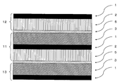
- One of the outermost layers of the battery is a negative electrode and the other is a positive electrode.
- a layer containing the negative electrode active material is formed only on one surface of the current collector.
- a layer containing the positive electrode active material is formed only on one surface of the current collector.
- One or more bipolar electrodes are interposed between the negative electrode and the positive electrode.
- the layer containing the negative electrode active material of the negative electrode and the layer containing the positive electrode active material of the bipolar electrode are arranged so as to face each other, and the layer containing the positive electrode active material of the positive electrode and the layer containing the negative electrode active material of the bipolar electrode face each other To place.
- bipolar electrodes When a plurality of bipolar electrodes are used, they are arranged so that the layer containing the negative electrode active material of one bipolar electrode faces the layer containing the positive electrode active material of the other bipolar electrode.
- a separator containing a solid electrolyte may be interposed between the negative electrode and the bipolar electrode and between the positive electrode and the bipolar electrode.
- a separator containing a solid electrolyte may be interposed between the bipolar electrodes.
- a solid electrolyte-forming electrode can be obtained by applying a polymerizable monomer solution in which sodium salt is dissolved to the surfaces of the negative electrode, bipolar electrode and positive electrode by the doctor blade method or the like and then polymerizing the polymerizable monomer after immersion. .
- the sodium secondary battery of the present invention can be manufactured by connecting lead wires to the outermost negative electrode current collector and positive electrode current collector of the multilayer electrode and storing the multilayer electrode in a container.
- carbon material 1 As carbon material 1, commercially available hard carbon (Carbotron P (trade name, registered trademark), manufactured by Kureha Battery Materials Japan Co., Ltd.), 0.001 MPa (gauge pressure display when atmospheric pressure is 0) The pressure was reduced to -0.1 MPa) at 200 ° C. for 12 hours and dried.
- a binder solution was prepared by dissolving 2% by mass of sodium polyacrylate (product number: 196-02955, degree of polymerization: 22,000 to 70,000) as a binder in 98% by mass of pure water.
- the negative electrode sheet 1 After cutting the negative electrode sheet described above to 50 mm ⁇ 50 mm, the negative electrode sheet 1 was produced by thickening with a biaxial roll press. The roll press was performed by adjusting the linear pressure between 10 and 500 kN / m so that the porosity of the electrode mixture (a mixture of carbon material and binder) was between 40 and 60%. The porosity of the electrode mixture can be determined according to a generally known method.
- the obtained slurry was filtered to separate a solid, washed with distilled water, and then dried at 100 ° C. to obtain a precipitate.
- the obtained mixture was put into an alumina firing vessel, fired by holding it in an air atmosphere at 900 ° C. for 6 hours using an electric furnace, and cooled to room temperature to obtain a composite metal oxide.
- HS100 acetylene black
- VT471 binder solution, 5% by weight, manufactured by Daikin Industries, Ltd.
- NMP N-methylpyrrolidone
- the obtained positive electrode mixture paste was applied to a 15 ⁇ m thick aluminum foil using a doctor blade so that the amount of active material after drying was 2.0 mAh / cm 2, and dried at 60 ° C. for 2 hours. After cutting to 50 mm ⁇ 50 mm, the positive electrode sheet 1 of the positive electrode was produced by thickening with a biaxial roll press (positive electrode sheet). The roll press conditions are the same as those of the negative electrode sheet 1 described above.
- the above-mentioned monomer solution 1 is applied to the positive electrode material coated surface of the above-described positive electrode sheet 1 and impregnated in the active material layer, and then sandwiched by two 100 mm ⁇ 100 mm 50 ⁇ m-thick PET sheets while blocking oxygen.
- the positive electrode electrolyte sheet 1 which makes [polymer / positive electrode] 1 unit is produced by heating and curing at 5 ° C. for 5 minutes and removing the PET sheet.
- bipolar electrode 1 In the same manner as the preparation of the positive electrode sheet 1, the positive electrode mixture paste was applied to the surface of the negative electrode sheet before being densified, dried at 60 ° C. for 2 hours, cut to 55 mm ⁇ 55 mm, and then biaxial A bipolar electrode (negative electrode / positive electrode) is prepared by densifying with a roll press. The roll press conditions are the same as those of the negative electrode sheet 1 described above. This electrode is hereinafter abbreviated as bipolar electrode sheet 1.
- bipolar sheet with separator 1 The above-mentioned bipolar sheet 1 is inserted into a bag made of a polyethylene separator.
- the bipolar sheet 1 with a separator is abbreviated.
- Bipolar Electrolyte Sheet 1 After the monomer solution 1 is applied to the bipolar sheet with a separator 1 described above and impregnated in the active material layer and the separator, it is sandwiched between two 100 mm ⁇ 100 mm 50 ⁇ m thick PET sheets and oxygen is blocked at 90 ° C. Heat for minutes to cure and remove the PET sheet. Subsequently, by cutting to 50 mm ⁇ 50 mm, a bipolar electrolyte sheet 1 having [polymer / negative electrode / positive electrode / polymer] that is not ionically connected on the back and front as one unit is produced (FIG. 2).
- Electrode electrolyte laminate 1 The above-described positive electrode electrolyte sheet 1 ([positive electrode / polymer]), bipolar electrolyte sheet 1 ([polymer / negative electrode / positive electrode / polymer]), and negative electrode electrolyte sheet 1 ([polymer / negative electrode]) are stacked to form an electrode electrolyte laminate 1. Make it.
- [Laminated continuum 1] The above-described electrode electrolyte laminate 1 is hot-pressed at 100 ° C. to produce a laminated continuum 1 in which the polymer layers of the positive electrolyte sheet 1, the bipolar electrolyte sheet 1, and the negative electrode electrolyte sheet 1 are integrated (FIG. 3). .
- Polymer bipolar battery 1 A lead for current extraction is attached to the positive electrode and negative electrode current collectors on both sides of the above-described laminated continuous body, and the polymer bipolar battery 1 (rated 50 mAh, average discharge voltage 6.2 V) is prepared by housing in an aluminum laminate case. .
- Electrode laminate 1 The positive electrode sheet 1, the separator-equipped bipolar sheet 1, and the negative electrode electrolyte sheet 1 are stacked to produce the electrode laminate 1.
- Electrode Bipolar Battery 1 A lead for current extraction is attached to the positive electrode and negative electrode current collectors on both sides of the above-described laminated continuous body, and the lead is accommodated in an aluminum laminate case, and the electrolytic solution 1 is injected into the electrolytic bipolar battery 1 (rated 50 mAh, An average discharge voltage of 6.2 V) is produced.
- Example 1 Except that the bipolar battery 1 of Example 1 is changed to the electrolyte bipolar battery 1, charging and discharging are performed in the same manner as in Example 1, and a recharge storage test is performed.
- the polymer bipolar battery 1 of the present invention has a voltage of 6 V or more even after one week, while the electrolyte bipolar battery 1 has a voltage of 4 V or less.
- the polymer bipolar battery 1 of the present invention has a separator for comparison, but operates as a battery without having a separator.
Landscapes
- Chemical & Material Sciences (AREA)
- Engineering & Computer Science (AREA)
- Electrochemistry (AREA)
- General Chemical & Material Sciences (AREA)
- Chemical Kinetics & Catalysis (AREA)
- Manufacturing & Machinery (AREA)
- Materials Engineering (AREA)
- Physics & Mathematics (AREA)
- Condensed Matter Physics & Semiconductors (AREA)
- General Physics & Mathematics (AREA)
- Inorganic Chemistry (AREA)
- Dispersion Chemistry (AREA)
- Secondary Cells (AREA)
Abstract
ナトリウムイオンをドープかつ脱ドープできる正極活物質を含む層と、ナトリウムイオンをドープかつ脱ドープできる負極活物質を含む層と、ナトリウムイオンを伝導できる電解質と、集電体とを有するナトリウム二次電池であって、前記集電体の一方の面上に前記正極活物質を含む層が積層され、他方の面上に前記負極活物質を含む層が積層された構造を有する集電体を少なくとも一つ有し、前記電解質が固体電解質であるナトリウム二次電池とすることにより、電池構造が単純なナトリウム二次電池が提供できる。
Description
本発明は、ナトリウム二次電池に関するものである。
近年、二次電池の研究開発が盛んに行われており、中でも、安価な材料であるナトリウムイオンを伝導イオンとして用いるナトリウム二次電池が注目を浴びている。
従来のナトリウム二次電池は、一枚の集電体の両面に正極活物質を含む層を積層させた構造単位と、一枚の集電体の両面に負極活物質を含む層を積層させた構造単位との間に、セパレータを介して積層させた構造を有するナトリウム二次電池であった(特開2010−225525公報)。
しかしながら、上記のナトリウム二次電池は、全ての集電体に、外部に電流を取り出す集電端子が必要なため、電池構造が複雑であった。
本発明はこのような事情に鑑みてなされたものであって、電池構造が単純なナトリウム二次電池を提供することにある。
本発明者は、上記課題を解決すべく鋭意検討を重ね、本発明に至った。
すなわち、本発明は、ナトリウムイオンをドープかつ脱ドープできる正極活物質を含む層と、ナトリウムイオンをドープかつ脱ドープできる負極活物質を含む層と、ナトリウムイオンを伝導できる電解質と、集電体とを有するナトリウム二次電池であって、 一枚の前記集電体の一方の面上に前記正極活物質を含む層が積層され、他方の面上に前記負極活物質を含む層が積層された集電体を少なくとも一つ有し、前記電解質が固体電解質であるナトリウム二次電池を提供する。
本発明によれば、電池構造が単純なナトリウム二次電池を提供することができる。ナトリウム二次電池は、安価な材料により構成することができるため、工業的に極めて有用である。
本実施形態のナトリウム二次電池は、ナトリウムイオンをドープかつ脱ドープできる正極活物質を含む層と、ナトリウムイオンをドープかつ脱ドープできる負極活物質を含む層と、ナトリウムイオンを伝導できる電解質と、集電体とを有するナトリウム二次電池であって、一枚の前記集電体の一方の面上に前記正極活物質を含む層が積層され、他方の面上に前記負極活物質を含む層が積層された集電体を少なくとも一つ有し、前記電解質が固体電解質である。
集電体の一方の面上に前記正極活物質を含む層が積層され、他方の面上に前記負極活物質を含む層が積層された構造をバイポーラ電極という。
以下、順に説明する。
以下、順に説明する。
<固体電解質>
本実施形態のナトリウム二次電池の電解質は、室温では固体で、ナトリウムイオンが伝導できる電解質である。従来、リチウム二次電池において、固体電解質はイオン伝導度が低すぎて、実電池として使用することは困難であったが、ナトリウム二次電池においては、十分なイオン伝導度が得られる。このような固体電解質を用いた場合、集電体の裏表でイオン的な短絡が起きないため集電体の裏表の絶縁部が不要になる。また、固体電解質が室温で液体の電解液と比較して難燃性が高いため、より安全性が高いナトリウム二次電池を提供することができる。
本実施形態のナトリウム二次電池の電解質は、室温では固体で、ナトリウムイオンが伝導できる電解質である。従来、リチウム二次電池において、固体電解質はイオン伝導度が低すぎて、実電池として使用することは困難であったが、ナトリウム二次電池においては、十分なイオン伝導度が得られる。このような固体電解質を用いた場合、集電体の裏表でイオン的な短絡が起きないため集電体の裏表の絶縁部が不要になる。また、固体電解質が室温で液体の電解液と比較して難燃性が高いため、より安全性が高いナトリウム二次電池を提供することができる。
前記固体電解質は、有機固体電解質であっても、無機固体電解質であってもよく、これらの混合物であってもよい。正極活物質と固体電解質との界面接合および負極活物質と固体電解質との界面接合を向上させる観点から、有機固体電解質であることが好ましい。有機固体電解質は、ナトリウムイオンを含むポリマーであることがより好ましい。
<有機固体電解質>
前記有機固体電解質は、例えば重合性モノマーと、ナトリウム塩と、必要に応じ、重合開始剤とを混合し、重合して得られる。また、重合性モノマーと、必要に応じ、重合開始剤とを混合し、重合した後に、得られた重合体と、ナトリウム塩とを溶媒に溶解して得てもよい。重合方法としては、熱重合、光重合、放射線重合などの重合方法があげられる。
前記有機固体電解質は、例えば重合性モノマーと、ナトリウム塩と、必要に応じ、重合開始剤とを混合し、重合して得られる。また、重合性モノマーと、必要に応じ、重合開始剤とを混合し、重合した後に、得られた重合体と、ナトリウム塩とを溶媒に溶解して得てもよい。重合方法としては、熱重合、光重合、放射線重合などの重合方法があげられる。
<重合性モノマー>
上述の重合性モノマーとしては、下記式(1)で表される構造単位および下記式(2)で表される構造単位からなる群より選ばれる一種以上の構造単位を含むモノマーを用いることができる。
−CH2−CH2−O− (1)
−CH2−CHCH3−O− (2)
上述の重合性モノマーとしては、下記式(1)で表される構造単位および下記式(2)で表される構造単位からなる群より選ばれる一種以上の構造単位を含むモノマーを用いることができる。
−CH2−CH2−O− (1)
−CH2−CHCH3−O− (2)
上記式(1)で表される構造単位および上記式(2)で表される構造単位からなる群より選ばれる一種以上の構造単位を含むモノマーとしては、例えば、新中村化学製のNKエステルA−200、A−400、A−600、APG−100、APG−200、APG−400、APG−700、A−GLY−9E、A−GLY−20E、A−TMMT、AD−TMP、ATM−35E、A−TMMT、A9550、A−DPHがあげられる。
<ナトリウム塩>
ナトリウム塩としては、例えば、NaPF6、NaBF4、NaClO4、NaCF3CONSO2CF3、NaN(SO2C2F5)2、NaN(SO2CF3)2、NaCF3SO3、NaC(CF3SO2)3があげられる。
ナトリウム塩としては、例えば、NaPF6、NaBF4、NaClO4、NaCF3CONSO2CF3、NaN(SO2C2F5)2、NaN(SO2CF3)2、NaCF3SO3、NaC(CF3SO2)3があげられる。
<重合開始剤>
重合開始剤としては、例えば、アゾ系重合開始剤、過酸化物系重合開始剤があげられる。
重合開始剤としては、例えば、アゾ系重合開始剤、過酸化物系重合開始剤があげられる。
アゾ系重合開始剤としては、2,2‘−アゾビス−イソブチロニトリル、2,2’−アゾビス−2−メチルブチロニトリル、2,2‘−アゾビス−2,4−ジメチルバレロニトリルがあげられる。
過酸化物系重合開始剤としては、イソブチルパーオキシド、ラウロイルパーオキシド、ベンゾイルパーオキシド、m−トルオイルパーオキシド、t−ブチルパーオキシ−2−エチルヘキサノエート、t−ブチルパーオキシバイバレート−ブチルオキシネオデカネート、ジイソプロピルパーオキシジカーボネート、ジエトキシパーオキシジカーボネート、ビス−(4−t−ブチルシクロヘキシル)パーオキシジカーボネート、ジメトキシイソプロピルパーオキシジカーボネート、ジシクロヘキシルパーオキシジカーボネート及び3,3,5−トリメチルヘキサノイルパーオキシドがあげられる。
<無機固体電解質>
無機固体電解質としては、市販の物を用いることができ、例えば、ナシコン型の固体電解質、硫化物系の固体電解質があげられる。
ナシコン型の固体電解質の組成としては、Na1+xZr2SixO12(xは0以上、3以下)を含むことが好ましい。
硫化物系の固体電解質の組成としては、例えばNa2SとP2S5を含むことが好ましい。
無機固体電解質としては、市販の物を用いることができ、例えば、ナシコン型の固体電解質、硫化物系の固体電解質があげられる。
ナシコン型の固体電解質の組成としては、Na1+xZr2SixO12(xは0以上、3以下)を含むことが好ましい。
硫化物系の固体電解質の組成としては、例えばNa2SとP2S5を含むことが好ましい。
<正極活物質を含む層>
本実施形態のナトリウム二次電池の正極活物質としては、ナトリウムのドープおよび脱ドープが可能なものを用いることができる。
本実施形態のナトリウム二次電池の正極活物質としては、ナトリウムのドープおよび脱ドープが可能なものを用いることができる。
正極活物質としては、ナトリウム金属、ナトリウム合金、ナトリウムイオンをドープかつ脱ドープ可能なナトリウム無機化合物をあげることができる。正極活物質を含む層は、例えば、Na化合物、バインダー及び導電剤等を含む電極合剤が、集電体に担持されているものであり、シート状であることが好ましい。
Na化合物を用いた正極活物質の製造方法としては、
(1)Na化合物、バインダー及び導電剤等に溶剤を添加してなる電極合剤を、集電体に、ドクターブレード法などで塗工、又は浸漬し、乾燥する方法、
(2)Na化合物、バインダー及び導電剤等に溶剤を添加して混練、成形し、乾燥して得たシートを集電体表面に導電性接着剤等を介して接合した後にプレス及び熱処理乾燥する方法、
(3)Na化合物、バインダー、導電剤及び液状潤滑剤等からなる混合物を集電体上に成形した後、液状潤滑剤を除去し、次いで、得られたシート状の成形物を一軸又は多軸方向に延伸処理する方法
などがあげられる。正極活物質を含む層がシート状である場合、その厚みは、5~500μm程度であることが好ましい。
(1)Na化合物、バインダー及び導電剤等に溶剤を添加してなる電極合剤を、集電体に、ドクターブレード法などで塗工、又は浸漬し、乾燥する方法、
(2)Na化合物、バインダー及び導電剤等に溶剤を添加して混練、成形し、乾燥して得たシートを集電体表面に導電性接着剤等を介して接合した後にプレス及び熱処理乾燥する方法、
(3)Na化合物、バインダー、導電剤及び液状潤滑剤等からなる混合物を集電体上に成形した後、液状潤滑剤を除去し、次いで、得られたシート状の成形物を一軸又は多軸方向に延伸処理する方法
などがあげられる。正極活物質を含む層がシート状である場合、その厚みは、5~500μm程度であることが好ましい。
Na化合物としては、
NaFeO2、NaMnO2、NaNiO2およびNaCoO2等のNaM1 aO2で表される酸化物、Na0.44Mn1−aM1 aO2で表される酸化物、Na0.7Mn1−aM1 aO2.05で表される酸化物(M1は1種以上の遷移金属元素、0≦a<1);
Na6Fe2Si12O30およびNa2Fe5Si12O30等のNabM2 cSi12O30で表される酸化物(M2は1種以上の遷移金属元素、2≦b≦6、2≦c≦5);
Na2Fe2Si6O18およびNa2MnFeSi6O18等のNadM3 eSi6O18で表される酸化物(M3は1種以上の遷移金属元素、3≦d≦6、1≦e≦2);
Na2FeSiO6等のNafM4 gSi2O6で表される酸化物(M4は遷移金属元素、MgおよびAlからなる群より選ばれる1種以上の元素、1≦f≦2、1≦g≦2);
NaFePO4、Na3Fe2(PO4)3等のリン酸塩;NaFeBO4、Na3Fe2(BO4)3等のホウ酸塩;
Na3FeF6およびNa2MnF6等のNahM5F6で表されるフッ化物(M5は1種以上の遷移金属元素、2≦h≦3);
等があげられる。
NaFeO2、NaMnO2、NaNiO2およびNaCoO2等のNaM1 aO2で表される酸化物、Na0.44Mn1−aM1 aO2で表される酸化物、Na0.7Mn1−aM1 aO2.05で表される酸化物(M1は1種以上の遷移金属元素、0≦a<1);
Na6Fe2Si12O30およびNa2Fe5Si12O30等のNabM2 cSi12O30で表される酸化物(M2は1種以上の遷移金属元素、2≦b≦6、2≦c≦5);
Na2Fe2Si6O18およびNa2MnFeSi6O18等のNadM3 eSi6O18で表される酸化物(M3は1種以上の遷移金属元素、3≦d≦6、1≦e≦2);
Na2FeSiO6等のNafM4 gSi2O6で表される酸化物(M4は遷移金属元素、MgおよびAlからなる群より選ばれる1種以上の元素、1≦f≦2、1≦g≦2);
NaFePO4、Na3Fe2(PO4)3等のリン酸塩;NaFeBO4、Na3Fe2(BO4)3等のホウ酸塩;
Na3FeF6およびNa2MnF6等のNahM5F6で表されるフッ化物(M5は1種以上の遷移金属元素、2≦h≦3);
等があげられる。
正極活物質を含む層において、上記のNa化合物の中では、Feを含有する化合物を好ましく用いることができる。Feを含有する化合物を使用することは、資源量が豊富で安価な材料により二次電池を構成する観点でも、非常に重要なことである。
正極活物質の表面には、さらに、バッファー層が有することが好ましい。バッファー層を有することで、電位勾配を持たせることが可能となり充放電がスムーズにできる。
正極活物質を含む層に用いられる導電剤としては、天然黒鉛、人造黒鉛、コークス類、カーボンブラックなど、各種炭素材料をあげることができる。また、負極活物質に用いられる炭素材料を、正極活物質を含む層における導電剤として、用いてもよい。
正極活物質を含む層を担持する集電体としては、
ニッケル、アルミニウム、チタン、銅、金、銀、白金、アルミニウム合金又はステンレス等の金属;
炭素素材、活性炭繊維、ニッケル、アルミニウム、亜鉛、銅、スズ、鉛又はこれらの合金をプラズマ溶射、アーク溶射することによって形成されたもの;
ゴム又はスチレン−エチレン−ブチレン−スチレン共重合体(SEBS)など樹脂に導電剤を分散させた導電性フィルム
などがあげられる。
これらの中でも、アルミニウム、アルミニウム合金、ニッケル、ステンレスなどが好ましく、薄膜に加工しやすく、安価であると観点から、アルミニウム、アルミニウム合金が好ましい。
ニッケル、アルミニウム、チタン、銅、金、銀、白金、アルミニウム合金又はステンレス等の金属;
炭素素材、活性炭繊維、ニッケル、アルミニウム、亜鉛、銅、スズ、鉛又はこれらの合金をプラズマ溶射、アーク溶射することによって形成されたもの;
ゴム又はスチレン−エチレン−ブチレン−スチレン共重合体(SEBS)など樹脂に導電剤を分散させた導電性フィルム
などがあげられる。
これらの中でも、アルミニウム、アルミニウム合金、ニッケル、ステンレスなどが好ましく、薄膜に加工しやすく、安価であると観点から、アルミニウム、アルミニウム合金が好ましい。
集電体の形状としては、例えば、箔状、平板状、メッシュ状、ネット状、ラス状もしくはパンチングメタル状であるもの、またはこれらを組み合わせたもの(例えば、メッシュ状平板など)等があげられる。また、集電体の表面にエッチング処理やエンボス加工による凹凸を形成させてもよい。
正極活物質を含む層において、バインダー、溶剤は、後述の負極活物質を含む層に用いられるものと同様のものを用いることができる。また、上記において、導電性接着剤とは、導電剤とバインダーとの混合物のことを意味する。
正極活物質を含む層中のバインダーの配合量は、Na化合物を正極活物質として用いた場合、Na化合物100質量部に対し、好ましくは0.5~30質量部程度、より好ましくは2~30質量部程度であり、導電剤の配合量は、Na化合物100質量部に対し、好ましくは1~50質量部程度、より好ましくは1~30質量部程度であり、溶剤の配合量は、Na化合物100質量部に対し、好ましくは50~500質量部程度、より好ましくは100~200質量部程度である。
<セパレータ>
本発明では、固体電解質を用いているのでセパレータを用いなくともよいが、重合性モノマーを固体電解質の原料として用いる場合、正極活物質を含む層と、負極活物質を含む層との距離を一定にする目的でセパレータを用いてもよい。また、固体電解質のピンホールなどによる正極活物質を含む層と、負極活物質を含む層とのショート防止の役割を果たす目的でセパレータを用いてもよい。
本発明では、固体電解質を用いているのでセパレータを用いなくともよいが、重合性モノマーを固体電解質の原料として用いる場合、正極活物質を含む層と、負極活物質を含む層との距離を一定にする目的でセパレータを用いてもよい。また、固体電解質のピンホールなどによる正極活物質を含む層と、負極活物質を含む層とのショート防止の役割を果たす目的でセパレータを用いてもよい。
セパレータとしては、例えば、ポリエチレン、ポリプロピレンなどのポリオレフィン樹脂、フッ素樹脂、含窒素芳香族重合体などの材質からなる、多孔質膜、不織布、織布などの形態を有する材料を用いることができ、また、前記の材質を2種以上用いてセパレータとしてもよいし、前記の材料が積層されていてもよい。セパレータとしては、例えば特開2000−30686号公報、特開平10−324758号公報等に記載のセパレータをあげることができる。
セパレータの孔径は、好ましくは0.01~10μm程度である。セパレータの厚さは、電池の体積エネルギー密度が上がり、内部抵抗が小さくなるという点で、機械的強度が保たれる限り薄くした方がよく、好ましくは1~300μm程度、より好ましくは5~40μm程度である。
セパレータは、イオン透過性との観点から、ガーレー法による透気度において、透気度が50~300秒/100ccであることが好ましく、50~200秒/100ccであることがさらに好ましい。
また、セパレータの空孔率は、好ましくは30~80体積%、より好ましくは40~70体積%である。セパレータは空孔率の異なるセパレータを積層したものであってもよい。
ナトリウム二次電池においては、正極活物質を含む層と、負極活物質を含む層との間の短絡等が原因で電池内に異常電流が流れた際に、短絡箇所の電流を遮断して、過大電流が流れることを阻止(シャットダウン)する機能を有することが好ましい。
セパレータが、熱可塑性樹脂を含有する多孔質フィルムを有する場合、シャットダウンは、短絡により短絡箇所のセパレータが過熱され、予め想定された(通常の)使用温度を越えた場合に、セパレータにおける多孔質フィルムが軟化または融解して微細孔を閉塞することによりなされる。そして、セパレータはシャットダウンした後、ある程度の高温まで電池内の温度が上昇しても、その温度により破膜することなく、シャットダウンした状態を維持する程度に耐熱性が高いことが好ましい。
このようなセパレータとしては、例えば、耐熱材料を有する多孔質フィルム、耐熱多孔層と多孔質フィルムとが積層された積層フィルムなどがあげられ、該フィルムをセパレータとして用いることにより、本実施形態のナトリウム二次電池の耐熱性をより高めることが可能となる。
次に、耐熱多孔層と多孔質フィルムとが積層された積層フィルムについて、より具体的に説明する。
該積層フィルムにおいて、耐熱多孔層は、多孔質フィルムよりも耐熱性の高い層であり、該耐熱多孔層は、後述する無機粉末から形成されていてもよいし、耐熱樹脂を含有していてもよい。耐熱多孔層が、耐熱樹脂を含有することにより、塗工などの容易な手法で、耐熱多孔層を形成することができる。
該積層フィルムにおいて、耐熱多孔層は、多孔質フィルムよりも耐熱性の高い層であり、該耐熱多孔層は、後述する無機粉末から形成されていてもよいし、耐熱樹脂を含有していてもよい。耐熱多孔層が、耐熱樹脂を含有することにより、塗工などの容易な手法で、耐熱多孔層を形成することができる。
耐熱樹脂としては、ポリアミド、ポリイミド、ポリアミドイミド、ポリカーボネート、ポリアセタール、ポリサルホン、ポリフェニレンサルファイド、ポリエーテルケトン、芳香族ポリエステル、ポリエーテルサルホン、ポリエーテルイミドをあげることができ、耐熱性をより高める観点で、ポリアミド、ポリイミド、ポリアミドイミド、ポリエーテルサルホン、ポリエーテルイミドが好ましく、ポリアミド、ポリイミド、ポリアミドイミドがより好ましい。さらにより好ましくは、芳香族ポリアミド(パラ配向芳香族ポリアミド、メタ配向芳香族ポリアミド)、芳香族ポリイミド、芳香族ポリアミドイミド等の含窒素芳香族重合体であり、とりわけ好ましくは芳香族ポリアミド、製造面で、特に好ましいのは、パラ配向芳香族ポリアミド(以下、「パラアラミド」ということがある。)である。
また、耐熱樹脂として、ポリ−4−メチルペンテン−1、環状オレフィン系重合体をあげることもできる。これらの耐熱樹脂を用いることにより、耐熱性を高めるすなわち、熱破膜温度を高めることができる。
上記の熱破膜温度は、耐熱樹脂の種類に依存し、使用場面、使用目的に応じ選択使用される。耐熱樹脂として、上記含窒素芳香族重合体を用いる場合は400℃程度に、また、ポリ−4−メチルペンテン−1を用いる場合は250℃程度に、環状オレフィン系重合体を用いる場合は300℃程度に、それぞれ熱破膜温度をコントロールすることができる。また、耐熱多孔層が、無機粉末からなる場合には、熱破膜温度を、例えば、500℃以上にコントロールすることも可能である。
上記パラアラミドは、パラ配向芳香族ジアミンとパラ配向芳香族ジカルボン酸ハライドの縮合重合により得られるものである。なお、例えば、4,4’−ビフェニレン、1,5−ナフタレン、2,6−ナフタレン等のような異なる芳香族環上であっても、パラ位に相当する配向位でアミド結合した繰返し単位からなるアラミドもパラアラミドに含む。具体的には、ポリ(パラフェニレンテレフタルアミド)、ポリ(パラベンズアミド)、ポリ(4,4’−ベンズアニリドテレフタルアミド)、ポリ(パラフェニレン−4,4’−ビフェニレンジカルボン酸アミド)、ポリ(パラフェニレン−2,6−ナフタレンジカルボン酸アミド)、ポリ(2−クロロ−パラフェニレンテレフタルアミド)、パラフェニレンテレフタルアミド/2,6−ジクロロパラフェニレンテレフタルアミド共重合体等のパラアラミドが例示される。
前記の芳香族ポリイミドとしては、芳香族の二酸無水物とジアミンの縮重合で製造される全芳香族ポリイミドが好ましい。該二酸無水物の具体例としては、ピロメリット酸二無水物、3,3’,4,4’−ジフェニルスルホンテトラカルボン酸二無水物、3,3’,4,4’−ベンゾフェノンテトラカルボン酸二無水物、2,2’−ビス(3,4−ジカルボキシフェニル)ヘキサフルオロプロパン、3,3’,4,4’−ビフェニルテトラカルボン酸二無水物などがあげられる。該ジアミンの具体例としては、オキシジアニリン、パラフェニレンジアミン、ベンゾフェノンジアミン、3,3’−メチレンジアニリン、3,3’−ジアミノベンソフェノン、3,3’−ジアミノジフェニルスルフォン、1,5’−ナフタレンジアミンなどがあげられる。また、溶媒に可溶なポリイミドが好適に使用できる。このようなポリイミドとしては、例えば、3,3’,4,4’−ジフェニルスルホンテトラカルボン酸二無水物と、芳香族ジアミンとの重縮合物のポリイミドがあげられる。
前記の芳香族ポリアミドイミドとしては、芳香族ジカルボン酸および芳香族ジイソシアネートの縮合重合から得られるもの、芳香族二酸無水物および芳香族ジイソシアネートを用いてこれらの縮合重合から得られるものがあげられる。芳香族ジカルボン酸の具体例としてはイソフタル酸、テレフタル酸などがあげられる。また芳香族二酸無水物の具体例としては無水トリメリット酸などがあげられる。芳香族ジイソシアネートの具体例としては、4,4’−ジフェニルメタンジイソシアネート、2,4−トリレンジイソシアネート、2,6−トリレンジイソシアネート、オルソトリランジイソシアネート、m−キシレンジイソシアネートなどがあげられる。
本実施形態において、ナトリウムイオン透過性をより高める意味で、耐熱多孔層の厚みは、1μm以上10μm以下、さらには1μm以上5μm以下、特に1μm以上4μm以下という薄い耐熱多孔層であることが好ましい。また、耐熱多孔層は微細孔を有し、その孔のサイズ(直径)は好ましくは3μm以下、より好ましくは1μm以下である。
また、耐熱多孔層が、耐熱樹脂を含有する場合には、フィラーをさらに含有することもできる。フィラーは、その材質として、有機粉末、無機粉末またはこれらの混合物のいずれから選ばれるものである。フィラーを構成する粒子は、その平均粒子径が、0.01μm以上1μm以下であることが好ましい。
前記有機粉末としては、例えば、スチレン、ビニルケトン、アクリロニトリル、メタクリル酸メチル、メタクリル酸エチル、グリシジルメタクリレート、グリシジルアクリレート、アクリル酸メチル等の単独あるいは2種類以上の共重合体、ポリテトラフルオロエチレン、4フッ化エチレン−6フッ化プロピレン共重合体、4フッ化エチレン−エチレン共重合体、ポリビニリデンフルオライド等のフッ素系樹脂;メラミン樹脂;尿素樹脂;ポリオレフィン;ポリメタクリレート等の有機物からなる粉末があげられる。該有機粉末は、単独で用いてもよいし、2種以上を混合して用いることもできる。これらの有機粉末の中でも、化学的安定性の点で、ポリテトラフルオロエチレン粉末が好ましい。
前記無機粉末としては、例えば、金属酸化物、金属窒化物、金属炭化物、金属水酸化物、炭酸塩、硫酸塩等の無機物からなる粉末があげられ、これらの中でも、導電性の低い無機物からなる粉末が好ましく用いられる。具体的に例示すると、アルミナ、シリカ、二酸化チタン、または炭酸カルシウム等からなる粉末があげられる。該無機粉末は、単独で用いてもよいし、2種以上を混合して用いることもできる。これらの無機粉末の中でも、化学的安定性の点で、アルミナ粉末が好ましい。ここで、フィラーを構成する粒子のすべてがアルミナ粒子であることがより好ましく、さらにより好ましいのは、フィラーを構成する粒子のすべてがアルミナ粒子であり、その一部または全部が略球状のアルミナ粒子である実施形態である。因みに、耐熱多孔層が、無機粉末から形成される場合には、上記例示の無機粉末を用いればよく、必要に応じてバインダーと混ぜて用いればよい。
耐熱多孔層が、耐熱樹脂を含有する場合のフィラーの含有量としては、フィラーの材質の比重にもよるが、例えば、耐熱多孔層の総質量を100としたとき、フィラーの質量は、好ましくは5以上95以下であり、より好ましくは20以上95以下であり、さらに好ましくは30以上90以下である。これらの範囲は、フィラーを構成する粒子のすべてがアルミナ粒子である場合に、特に好適である。
フィラーの形状については、略球状、板状、柱状、針状、ウィスカー状、繊維状等があげられ、いずれの粒子も用いることができるが、均一な孔を形成しやすいことから、略球状粒子であることが好ましい。略球状粒子としては、粒子のアスペクト比(粒子の長径/粒子の短径)が1以上1.5以下の範囲の値である粒子があげられる。粒子のアスペクト比は、電子顕微鏡写真により測定することができる。
上述のように、耐熱多孔層は、2種以上のフィラーを含有することもできる。この場合、該2種以上のフィラーのそれぞれにつき構成する粒子の平均粒子径を測定して得られる値のうち、1番目に大きい値をD1、2番目に大きい値をD2としたとき、D2/D1の値が0.15以下であることが好ましい。このことにより、積層フィルムの耐熱多孔層の微細孔において、サイズが比較的小さな微細孔と、サイズが比較的大きな微細孔と、がバランス良く生じる。サイズが比較的小さな微細孔の構造により、積層フィルムからなるセパレータの耐熱性を高めることができ、サイズが比較的大きな微細孔の構造により、ナトリウムイオン透過性を高め、得られるナトリウム二次電池においては、高い電流レートにおいて高出力とすることができる、すなわちレート特性に優れ、好適なセパレータとすることができる。
上記平均粒子径は、電子顕微鏡写真から測定される値を用いればよい。すなわち、積層フィルムにおける耐熱多孔層の表面または断面の走査型電子顕微鏡写真に撮影されている粒子(フィラー粒子)をそのサイズ別に分類して、各分類における平均粒子径の値のうち、1番目に大きい値をD1、2番目に大きい値をD2としたとき、D2/D1の値が0.15以下であればよい。平均粒子径は、上記の各分類において25個ずつ粒子を任意に抽出して、それぞれにつき粒子径(直径)を測定して、25個の粒子径の平均値を平均粒子径とする。なお、上記のフィラーを構成する粒子は、フィラーを構成する一次粒子のことを意味する。
積層フィルムにおいて、多孔質フィルムは、微細孔を有し、シャットダウン機能を有することが好ましい。多孔質フィルムにおける微細孔のサイズ(直径)は好ましくは3μm以下、より好ましくは1μm以下である。多孔質フィルムの空孔率は、好ましくは30~80体積%、より好ましくは40~70体積%である。ナトリウム二次電池において、通常の使用温度を越えた場合には、シャットダウン機能により、多孔質フィルムの変形、軟化により、微細孔を閉塞することができる。
本実施形態において、多孔質フィルムを構成する樹脂は、具体的には、ポリエチレン、ポリプロピレンなどのポリオレフィン樹脂、熱可塑性ポリウレタン樹脂をあげることができ、これらの2種以上の混合物を用いてもよい。より低温で軟化してシャットダウンさせる意味で、多孔質フィルムは、ポリオレフィン樹脂を含有することが好ましく、より好ましくは、ポリエチレンを含有することである。ポリエチレンとして、具体的には、低密度ポリエチレン、高密度ポリエチレン、線状ポリエチレン等のポリエチレンをあげることができ、超高分子量ポリエチレンをあげることもできる。多孔質フィルムの突刺し強度をより高める意味では、それを構成する樹脂は、少なくとも超高分子量ポリエチレンを含有することが好ましい。また、多孔質フィルムの製造面において、低分子量(重量平均分子量1万以下)のポリオレフィンからなるワックスを含有することが好ましい場合もある。
また、多孔質フィルムの厚みは、好ましくは3~30μmであり、より好ましくは3~20μmである。また、積層フィルムの厚みとしては、好ましくは40μm以下、より好ましくは、20μm以下である。また、耐熱多孔層の厚みをA(μm)、多孔質フィルムの厚みをB(μm)としたときには、A/Bの値が、0.1以上1以下であることが好ましい。
次に、積層フィルムの製造の一例について説明する。
まず、多孔質フィルムの製造方法について説明する。多孔質フィルムの製造は特に限定されるものではなく、例えば特開平7−29563号公報に記載されたように、熱可塑性樹脂に可塑剤を加えてフィルム成形した後、該可塑剤を適当な溶媒で除去する方法や、特開平7−304110号公報に記載されたように、公知の方法により製造した熱可塑性樹脂からなるフィルムを用い、該フィルムの構造的に弱い非晶部分を選択的に延伸して微細孔を形成する方法があげられる。
まず、多孔質フィルムの製造方法について説明する。多孔質フィルムの製造は特に限定されるものではなく、例えば特開平7−29563号公報に記載されたように、熱可塑性樹脂に可塑剤を加えてフィルム成形した後、該可塑剤を適当な溶媒で除去する方法や、特開平7−304110号公報に記載されたように、公知の方法により製造した熱可塑性樹脂からなるフィルムを用い、該フィルムの構造的に弱い非晶部分を選択的に延伸して微細孔を形成する方法があげられる。
例えば、多孔質フィルムが、超高分子量ポリエチレンおよび重量平均分子量1万以下の低分子量ポリオレフィンを含むポリオレフィン樹脂から形成されてなる場合には、製造コストの観点から、以下に示すような製造方法が好ましい。
すなわち、多孔質フィルムの第1の製造方法としては、
(1)超高分子量ポリエチレン100質量部と、重量平均分子量1万以下の低分子量ポリオレフィン5~200質量部と、無機充填剤100~400質量部とを混練してポリオレフィン樹脂組成物を得る工程
(2)前記ポリオレフィン樹脂組成物を用いてシートを成形する工程
(3)工程(2)で得られたシート中から後述する無機充填剤を除去する工程
(4)工程(3)で得られたシートを延伸して多孔質フィルムを得る工程
を含む方法があげられる。
(1)超高分子量ポリエチレン100質量部と、重量平均分子量1万以下の低分子量ポリオレフィン5~200質量部と、無機充填剤100~400質量部とを混練してポリオレフィン樹脂組成物を得る工程
(2)前記ポリオレフィン樹脂組成物を用いてシートを成形する工程
(3)工程(2)で得られたシート中から後述する無機充填剤を除去する工程
(4)工程(3)で得られたシートを延伸して多孔質フィルムを得る工程
を含む方法があげられる。
また、多孔質フィルムの第2の製造方法としては、
(1)超高分子量ポリエチレン100質量部と、重量平均分子量1万以下の低分子量ポリオレフィン5~200質量部と、無機充填剤100~400質量部とを混練してポリオレフィン樹脂組成物を得る工程
(2)前記ポリオレフィン樹脂組成物を用いてシートを成形する工程
(3)工程(2)で得られたシートを延伸する工程
(4)工程(3)で得られた延伸シート中から、無機充填剤を除去して多孔質フィルムを得る工程
を含む方法があげられる。
(1)超高分子量ポリエチレン100質量部と、重量平均分子量1万以下の低分子量ポリオレフィン5~200質量部と、無機充填剤100~400質量部とを混練してポリオレフィン樹脂組成物を得る工程
(2)前記ポリオレフィン樹脂組成物を用いてシートを成形する工程
(3)工程(2)で得られたシートを延伸する工程
(4)工程(3)で得られた延伸シート中から、無機充填剤を除去して多孔質フィルムを得る工程
を含む方法があげられる。
多孔質フィルムの強度およびイオン透過性の観点から、用いる無機充填剤は、平均粒子径(直径)が0.5μm以下であることが好ましく、0.2μm以下であることがさらに好ましい。ここで、平均粒子径は、電子顕微鏡写真から測定される値を用いる。具体的には、該写真に撮影されている無機充填剤粒子から任意に50個抽出し、それぞれの粒子径を測定して、その平均値を用いる。
上記無機充填剤としては、炭酸カルシウム、炭酸マグネシウム、炭酸バリウム、酸化亜鉛、酸化カルシウム、水酸化アルミニウム、水酸化マグネシウム、水酸化カルシウム、硫酸カルシウム、珪酸、酸化亜鉛、塩化カルシウム、塩化ナトリウム、硫酸マグネシウムなどがあげられる。これらの無機充填剤は酸、あるいはアルカリ溶液によりシートまたはフィルム中から除去することができる。粒子径の制御性、酸への選択的溶解性の観点から炭酸カルシウムを用いることが好ましい。
上記ポリオレフィン樹脂組成物の製造方法は特に限定されないが、ポリオレフィン樹脂や無機充填剤等のポリオレフィン樹脂組成物を構成する材料を混合装置、例えばロール、バンバリーミキサー、一軸押出機、二軸押出機などを用いて混合し、ポリオレフィン樹脂組成物を得る。材料を混合する際に、必要に応じて脂肪酸エステルや安定化剤、酸化防止剤、紫外線吸収剤、難燃剤等の添加剤を添加してもよい。
上記ポリオレフィン樹脂組成物からなるシートの製造方法は特に限定されるものではなく、インフレーション加工、カレンダー加工、Tダイ押出加工、スカイフ法等のシート成形方法により製造することができる。より膜厚精度の高いシートが得られることから、下記の方法により製造することが好ましい。
ポリオレフィン樹脂組成物からなるシートの好ましい製造方法とは、ポリオレフィン樹脂組成物に含有されるポリオレフィン樹脂の融点より高い表面温度に調整された一対の回転成形工具を用いて、ポリオレフィン樹脂組成物を圧延成形する方法である。回転成形工具の表面温度は、(融点+5)℃以上であることが好ましい。また表面温度の上限は、(融点+30)℃以下であることが好ましく、(融点+20)℃以下であることがさらに好ましい。一対の回転成形工具としては、ロールやベルトがあげられる。両回転成形工具の周速度は必ずしも厳密に同一周速度である必要はなく、それらの差異が±5%以内程度であればよい。このような方法により得られるシートを用いて多孔質フィルムを製造することにより、強度やイオン透過、透気性などに優れる多孔質フィルムを得ることができる。また、前記したような方法により得られる単層のシート同士を積層したものを、多孔質フィルムの製造に使用してもよい。
ポリオレフィン樹脂組成物を一対の回転成形工具により圧延成形する際には、押出機よりストランド状に吐出したポリオレフィン樹脂組成物を直接一対の回転成形工具間に導入してもよく、一旦ペレット化したポリオレフィン樹脂組成物を用いてもよい。
ポリオレフィン樹脂組成物からなるシートまたは該シートから無機充填剤を除去したシートを延伸する際には、テンター、ロールあるいはオートグラフ等を用いることができる。透気性の面から延伸倍率は2~12倍が好ましく、より好ましくは4~10倍である。延伸温度は、好ましくはポリオレフィン樹脂の軟化点以上融点以下の温度で行われ、80~115℃で行うことがより好ましい。延伸温度が低すぎると延伸時に破膜しやすくなり、高すぎると得られるフィルムの透気性やイオン透過性が低くなることがある。また延伸後はヒートセットを行うことが好ましい。ヒートセット温度はポリオレフィン樹脂の融点未満の温度であることが好ましい。
本実施形態においては、前記したような方法で得られる熱可塑性樹脂を含有する多孔質フィルムと、耐熱多孔層とを積層して、積層フィルムを得る。耐熱多孔層は多孔質フィルムの片面に設けられていてもよく、両面に設けられていてもよい。
多孔質フィルムと耐熱多孔層とを積層する方法としては、耐熱多孔層と多孔質フィルムとを別々に製造してそれぞれを積層する方法、多孔質フィルムの少なくとも片面に、耐熱樹脂とフィラーとを含有する塗工液を塗工して耐熱多孔層を形成する方法等があげられるが、本実施形態において、耐熱多孔層は比較的薄い場合には、その生産性の面から後者の手法が好ましい。
多孔質フィルムの少なくとも片面に、耐熱樹脂とフィラーとを含有する塗工液を塗布して耐熱樹脂層を形成する方法としては、具体的に以下のような工程を含む方法があげられる。
(a)耐熱樹脂100質量部を含む極性有機溶媒溶液に、該耐熱樹脂100質量部に対しフィラーを1~1500質量部分散したスラリー状塗工液を調製する。
(b)該塗工液を多孔質フィルムの少なくとも片面に塗工し、塗工膜を形成する。
(c)加湿、溶媒除去あるいは耐熱樹脂を溶解しない溶媒への浸漬等の手段で、前記塗工膜から耐熱樹脂を析出させた後、必要に応じて乾燥する。
(a)耐熱樹脂100質量部を含む極性有機溶媒溶液に、該耐熱樹脂100質量部に対しフィラーを1~1500質量部分散したスラリー状塗工液を調製する。
(b)該塗工液を多孔質フィルムの少なくとも片面に塗工し、塗工膜を形成する。
(c)加湿、溶媒除去あるいは耐熱樹脂を溶解しない溶媒への浸漬等の手段で、前記塗工膜から耐熱樹脂を析出させた後、必要に応じて乾燥する。
塗工液は、特開2001−316006号公報に記載の塗工装置および特開2001−23602号公報に記載の方法により連続的に塗工することが好ましい。
また、前記の極性有機溶媒溶液において、耐熱樹脂がパラアラミドである場合には、極性有機溶媒として、極性アミド系溶媒または極性尿素系溶媒を用いることができ、具体的には、N,N−ジメチルホルムアミド、N,N−ジメチルアセトアミド、N−メチル−2−ピロリドン(NMP)、テトラメチルウレア等があげられるが、これらに限定されるものではない。
耐熱樹脂としてパラアラミドを用いる場合、パラアラミドの溶媒への溶解性を改善する目的で、パラアラミド重合時にアルカリ金属またはアルカリ土類金属の塩化物を添加することが好ましい。具体例としては、塩化リチウムまたは塩化カルシウムがあげられるが、これらに限定されるものではない。上記塩化物の重合系への添加量は、縮合重合で生成するアミド基1.0モル当たり0.5~6.0モルの範囲が好ましく、1.0~4.0モルの範囲がさらに好ましい。塩化物が0.5モル未満では、生成するパラアラミドの溶解性が不十分となる場合があり、6.0モルを超えると実質的に塩化物の溶媒への溶解度を越えるので好ましくない場合がある。一般には、アルカリ金属またはアルカリ土類金属の塩化物が2質量%未満では、パラアラミドの溶解性が不十分となる場合があり、10質量%を越えてはアルカリ金属またはアルカリ土類金属の塩化物が極性アミド系溶媒または極性尿素系溶媒等の極性有機溶媒に溶解しない場合がある。
また、耐熱樹脂が芳香族ポリイミドである場合には、芳香族ポリイミドを溶解させる極性有機溶媒として、アラミドを溶解させる溶媒として例示したもののほか、ジメチルスルホキサイド、クレゾール、およびo−クロロフェノール等が好適に使用できる。
フィラーを分散させてスラリー状塗工液を得る方法としては、その装置として、圧力式分散機(ゴーリンホモジナイザー、ナノマイザー)等を用いればよい。
スラリー状塗工液を塗工する方法としては、例えばナイフ、ブレード、バー、グラビア、ダイ等の塗工方法があげられ、バー、ナイフ等の塗工が簡便であるが、工業的には、溶液が外気と接触しない構造のダイ塗工が好ましい。また、塗工は2回以上行う場合もある。この場合、上記工程(c)において耐熱樹脂を析出させた後に行うのが通常である。
また、前記の耐熱多孔層と多孔質フィルムとを別々に製造してそれぞれを積層する場合においては、接着剤による方法、熱融着による方法等により、固定化しておくのがよい。
<負極活物質を含む層>
本実施形態のナトリウム二次電池の負極活物質は、ナトリウムのドープおよび脱ドープが可能な公知の電極活物質を用いることができる。中でも、炭素材料であることが好ましく、前記炭素材料は、難黒鉛化炭素または易黒鉛化炭素であることがより好ましい。
本実施形態のナトリウム二次電池の負極活物質は、ナトリウムのドープおよび脱ドープが可能な公知の電極活物質を用いることができる。中でも、炭素材料であることが好ましく、前記炭素材料は、難黒鉛化炭素または易黒鉛化炭素であることがより好ましい。
ここで、「難黒鉛化炭素」とは、不活性雰囲気中で加熱しても黒鉛になりにくい炭素材料であり、ハードカーボンとも呼ばれる材料である。微小な黒鉛の結晶を不規則に有しており、結晶と結晶の間に数nmの大きさの空孔を有している。
また、「易黒鉛化炭素」とは、2500℃以上の高温での加熱処理によって三次元的な積層規則性を持つ黒鉛構造が生成しやすい(黒鉛になりやすい)炭素材料であり、ソフトカーボンとも呼ばれる材料である。
「難黒鉛化炭素」および「易黒鉛化炭素」は、いずれも炭素材料粉末のX線回折測定によって調べることができる002面の格子面間隔の値が、黒鉛の002面の格子面間隔の値である3.3Å(0.33nm)~3.4Å(0.34nm)よりも大きい。すなわち「難黒鉛化炭素」および「易黒鉛化炭素」は、いずれもグラフェン構造を有する層を有しているが、各層間の間隔が3.4Å(0.34nm)よりも大きいものとなっている。このような構造を有することにより、上記層間の隙間にナトリウムがドープ(挿入)され、または脱ドープ(脱離)することが可能となる。
各層間の間隔は、易黒鉛化炭素よりも難黒鉛化炭素のほうが広い。そのため、易黒鉛化炭素よりも難黒鉛化炭素のほうが、加熱によりグラフェン構造を有する層が再配列し黒鉛が生成する反応が起こりにくく、その結果、高温環境下で容量低下を生じにくくなるため好ましい。
なお、X線回折測定においては、Cu−Kα線をターゲットとした場合、2θが23度から27度付近に002回折線が得られ、002面の格子面間隔を測定することができる。
さらに、上記炭素材料は、難黒鉛化炭素であり、以下の条件1、条件2、条件3および条件4からなる群から選ばれる1つ以上の要件を満たすことが好ましい。
[条件1]
条件1は、波長532nmのレーザーを用いてラマン分光測定を行い、得られるラマンスペクトルが、1300~1400cm−1の波長範囲および1570~1620cm−1の範囲のそれぞれに1つずつピークを有し、前記ラマンスペクトルの600~1740cm−1の波長範囲について、2つのローレンツ関数および1つのベースライン関数を用いてフィッティングを行ってフィッティング関数を得た後、前記フィッティング関数からフィッティング後のベースライン関数を減じて得られるフィッティングスペクトルにおいて、1300~1400cm−1の波長範囲における散乱強度の最大値をID、1570~1620cm−1の波長範囲における最大値をIGとし、IDをIGで除して得られるRが、1.07以上3以下である、というものである。このような炭素材料を負極活物質として用いると、ナトリウム二次電池において、ナトリウムイオンを効率よくドープおよび脱ドープすることができる。また、このような炭素材料を負極活物質として用いたナトリウム二次電池を充放電させると、充放電を繰り返しても、放電容量が下がりにくい。
条件1は、波長532nmのレーザーを用いてラマン分光測定を行い、得られるラマンスペクトルが、1300~1400cm−1の波長範囲および1570~1620cm−1の範囲のそれぞれに1つずつピークを有し、前記ラマンスペクトルの600~1740cm−1の波長範囲について、2つのローレンツ関数および1つのベースライン関数を用いてフィッティングを行ってフィッティング関数を得た後、前記フィッティング関数からフィッティング後のベースライン関数を減じて得られるフィッティングスペクトルにおいて、1300~1400cm−1の波長範囲における散乱強度の最大値をID、1570~1620cm−1の波長範囲における最大値をIGとし、IDをIGで除して得られるRが、1.07以上3以下である、というものである。このような炭素材料を負極活物質として用いると、ナトリウム二次電池において、ナトリウムイオンを効率よくドープおよび脱ドープすることができる。また、このような炭素材料を負極活物質として用いたナトリウム二次電池を充放電させると、充放電を繰り返しても、放電容量が下がりにくい。
本実施形態において、ラマンスペクトルは、顕微ラマン分光装置(日本分光株式会社製、型番NRS−1000)を用い、照射光として波長532nmのレーザー、出力5mW、シングル分光器、電子冷却式CCD検出器を用い、照射時間15秒、積算回数10回で測定することで得ることができる。得られるラマンスペクトルは、縦軸が任意単位の散乱光強度であり、横軸がラマンシフトの波数(単位:cm−1)である。
なお、ラマン分光測定は、負極活物質である炭素材料をそのまま測定することもできるし、炭素材料を有する負極活物質を含む層について測定してもよい。この場合、負極活物質を含む層の作製条件としては、炭素材料とポリフッ化ビニリデンとを質量比が85:15となるように秤量して、これらをN−メチル−2−ピロリドン(NMP)に分散させて、得られたスラリーを銅箔上に0.1mm塗布して、150℃で真空乾燥する条件が推奨される。また、負極活物質を含む層についてラマン分光測定を行うときは、負極活物質である炭素材料が塗布された面に、レーザーを照射する。
上記Rは以下の(1)~(4)により得る。
(1)2つのローレンツ関数および1つのベースライン関数を用い、下記式(a)を得る。
y=〔A1/{(x−x1)2+B1 2}〕+〔A2/{(x−x2)2+B2 2}〕+〔C1x3+C2x2+C3x+C4〕 …(a)
y=〔A1/{(x−x1)2+B1 2}〕+〔A2/{(x−x2)2+B2 2}〕+〔C1x3+C2x2+C3x+C4〕 …(a)
なお、右辺第1項は、1300~1400cm−1の波数範囲のラマンスペクトルを示す応答関数であるローレンツ関数であり、A1はこの範囲のピークの最大散乱強度、B1は該ピークの半値半幅(単位:cm−1)、x1は該ピークの散乱強度の最大値における波数(単位:cm−1)である。
右辺第2項は、1570~1620cm−1の波数範囲のラマンスペクトルを示す応答関数であるローレンツ関数であり、A2はこの範囲のピークの最大散乱強度、B2は該ピークの半値半幅(単位:cm−1)、x2は該ピークの散乱強度の最大値における波数(単位:cm−1)である。
右辺第3項は、3次多項式を用いたベースライン関数である。
上記式(a)においては、A1、B1、x1、A2、B2、x2、C1、C2、C3およびC4は未知数である。
右辺第2項は、1570~1620cm−1の波数範囲のラマンスペクトルを示す応答関数であるローレンツ関数であり、A2はこの範囲のピークの最大散乱強度、B2は該ピークの半値半幅(単位:cm−1)、x2は該ピークの散乱強度の最大値における波数(単位:cm−1)である。
右辺第3項は、3次多項式を用いたベースライン関数である。
上記式(a)においては、A1、B1、x1、A2、B2、x2、C1、C2、C3およびC4は未知数である。
(2)一方、実測したラマンスペクトルの600~1740cm−1の波数範囲におけるデータ点(x、y)を1000点以上用いて、最小二乗法により、上記A1、B1、x1、A2、B2、x2、C1、C2、C3およびC4の最適値を求め、上記式(a)のフィッティングを行う。これにより、上記式(a)にA1、B1、x1、A2、B2、x2、C1、C2、C3およびC4の最適値を代入したフィッティング関数を得る。
(3)フィッティング関数から右辺第3項(ベースライン関数)を減じて、フィッティングスペクトルを得る。フィッティングスペクトルは、下記式(b)で表される。
y=〔A1/{(x−x1)2+B1 2}〕+〔A2/{(x−x2)2+B2 2}〕 …(b)
y=〔A1/{(x−x1)2+B1 2}〕+〔A2/{(x−x2)2+B2 2}〕 …(b)
(4)フィッティングスペクトルにおいて、1300~1400cm−1の波数範囲における散乱光強度の最大値をID、1570~1620cm−1の波数範囲における散乱光強度の最大値をIGとし、IDをIGで除して(ID/IG)、Rを得る。なお、Rの値は、A1/A2の値と一致する。
また、上記のフィッティングスペクトルにおいて、1300~1400cm−1の波数範囲のピークの最大散乱強度を、この最大強度を示すピークの半値半幅で除したA1/B1と、1570~1620cm−1の波数範囲のピークの最大強度を、この最大強度を示すピークの半値半幅で除したA2/B2と、を求め、(A1/B1)を(A2/B2)で除して((A1×B2)/(B1×A2))、NR値を得る。
また、本実施形態において、上記のフィッティングは、ソフトウェア「Igor Pro(名称)、Wave Metrics製」を用いて行う。
Rは、本実施形態のナトリウム二次電池の充放電容量をより高める意味で、1.10以上3以下であることが好ましく、1.3以上3以下であることがより好ましい。
B1は、本実施形態のナトリウム二次電池の充放電容量をより高める意味で、25cm−1以上100cm−1以下の範囲であることが好ましい。
NRは、本実施形態のナトリウム二次電池の充放電容量をより高める意味で、0.62以上であることが好ましい。
[条件2]
次に、本実施形態のナトリウム二次電池の負極活物質として用いられる炭素材料が満たすべき条件のうち、条件2について説明する。
次に、本実施形態のナトリウム二次電池の負極活物質として用いられる炭素材料が満たすべき条件のうち、条件2について説明する。
条件2は、X線小角散乱測定により得られるX線小角散乱スペクトルにおいて、0.6nm−1以上1.8nm−1以下の波数範囲について最小二乗法で直線近似して得られる近似直線の傾きをA、前記Aの標準偏差をσAとしたとき、前記Aが−0.5以上0以下であり、かつ前記σAが0以上0.010以下である、というものである。
このような炭素材料を負極活物質として用いると、充放電特性に優れたナトリウム二次電池が得られる。
このような炭素材料を負極活物質として用いると、充放電特性に優れたナトリウム二次電池が得られる。
本実施形態において、X線小角散乱測定は、二次元検出器搭載のX線小角散乱装置(NanoSTAR、ブルカー・エイエックスエス株式会社製)を用いて行う。
以下、測定の具体例につき、説明する。
測定対象である炭素材料を内径1mmの石英製キャピラリに充填し、これにCuターゲットの回転対陰極型のX線発生器を用い、出力50kV、100mAで発生させたX線を照射する。上記X線小角散乱装置を用いた測定では、X線は、クロスカップルド・ゲーベルミラーと3つのピンホールスリット(スリットの孔径はX線発生器側から500μmφ、150μmφ、500μmφ)からなるX線の光学系を通って、さらに石英製キャピラリを通って、炭素材料に照射されることになる。
測定対象である炭素材料を内径1mmの石英製キャピラリに充填し、これにCuターゲットの回転対陰極型のX線発生器を用い、出力50kV、100mAで発生させたX線を照射する。上記X線小角散乱装置を用いた測定では、X線は、クロスカップルド・ゲーベルミラーと3つのピンホールスリット(スリットの孔径はX線発生器側から500μmφ、150μmφ、500μmφ)からなるX線の光学系を通って、さらに石英製キャピラリを通って、炭素材料に照射されることになる。
炭素材料で散乱したX線は、二次元検出器(2次元Multi Wire検出器、Hi−STAR)を用いて検出される。試料から検知器までのカメラ長は106cmで、ダイレクトビームストッパーの大きさは2mmφである。装置内の真空度は40Pa以下である。散乱角2θとダイレクトビーム位置の校正は、ベヘン酸銀の1次(2θ=1.513°)と2次(2θ=3.027°)のそれぞれのピークを用いて行う。この場合、測定可能な散乱角2θの範囲は0.08~3°である。
検出される二次元の散乱像を、解析ソフト(SAXS Ver.4.1.29、ブルカー・エイエックスエス社製)を用いて常法に従って解析し、X線小角散乱スペクトルを得る。得られるX線小角散乱スペクトルは、横軸が波数q(nm−1)、縦軸がS(散乱強度Iの常用対数:log(I))である。
また、炭素材料が入っていない石英製キャピラリのみについても上記と同様にして測定し、ブランクのX線小角散乱スペクトル(以下、「ブランク」と称することがある)を得る。炭素材料のX線小角散乱スペクトルにおけるq=0.6nm−1のときのSの値が、ブランクにおけるq=0.6nm−1の値の10倍以上である場合、炭素材料のX線小角散乱スペクトルは、信頼できるものとする。
また、X線小角散乱スペクトルの0.6nm−1以上1.8nm−1以下の波数範囲について、最小二乗法により直線近似して近似直線を求め、近似直線の傾きAおよびAの標準偏差σAを求める。AおよびσAの算出には、ソフトウェア「Igor Pro(名称)、Wave Metrics製」を用いる。直線近似は、0.6nm−1以上1.8nm−1以下の波数範囲において等間隔で100点に区画して行う。
[条件3]
次に、本実施形態のナトリウム二次電池の負極活物質として用いられる炭素材料が満たすべき条件のうち、条件3について説明する。
次に、本実施形態のナトリウム二次電池の負極活物質として用いられる炭素材料が満たすべき条件のうち、条件3について説明する。
条件3は、炭素材料85質量部とポリフッ化ビニリデン15質量部とを混合して得られる電極合剤を有する電極について、ナトリウムイオンのドープおよび脱ドープがなされた後の電極における炭素材料に、10nm以上の細孔が実質的に存在しない、というものである。
このような炭素材料を負極活物質として用いると、充放電特性に優れたナトリウム二次電池が得られる。
このような炭素材料を負極活物質として用いると、充放電特性に優れたナトリウム二次電池が得られる。
具体的には、まず、炭素材料85質量部とポリフッ化ビニリデン15質量部とを混合して得られる電極合剤を有する電極を負極として用い、ナトリウム金属を対極として用いて、ナトリウム二次電池を作製し、負極から対極に向けて電流を流す。これにより、負極にナトリウムイオンをドープする。ナトリウムイオンのドープは、炭素材料1gあたり10mAの電流で、0.005Vになるまで、定電流で行う。
次いで、上記操作によりナトリウムイオンをドープした負極を有するナトリウム二次電池について、対極から負極に向けて電流を流す。これにより負極からナトリウムイオンを脱ドープする。ナトリウムイオンの脱ドープは、炭素材料1gあたり10mAの電流で、1.5Vになるまで、定電流で行う。
負極からナトリウムイオンを脱ドープした後、電池を乾燥Ar、窒素中など不活性雰囲気中で分解して、負極を取り出し、ジメチルカーボネート(以下、DMCということもある。)で洗浄し、真空中で乾燥後、電極合剤を回収する。
本実施形態において、炭素材料に、直径10nm以上の細孔が実質的に存在しないことは、透過型電子顕微鏡(TEM)を用いて、明視野像の像観察により確認する。
具体的には、回収した電極合剤について、集束イオンビーム加工装置を用い、回収した電極合剤に含まれる炭素材料の粒子について、厚みが100nm~200nm程度の切片を作製する。得られた切片について、加速電圧200kVで、像観察することにより、像視野の炭素材料に、直径10nm以上の細孔が実質的に存在しないことを確認する。
なお、本実施形態において、細孔の直径は、上記方法による像観察で得られる細孔の像についての面積相当径として求める。
なお、各操作間の試料の移送は不活性雰囲気中で行う。
また、本実施形態において、炭素材料の細孔は、炭素材料内部にある細孔であってもよいし、また表面にあってもよい。いずれにおいても、上記の像観察により判断される。
[条件4]
次に、本実施形態のナトリウム二次電池の負極活物質として用いられる炭素材料が満たすべき条件のうち、条件4について説明する。
次に、本実施形態のナトリウム二次電池の負極活物質として用いられる炭素材料が満たすべき条件のうち、条件4について説明する。
条件4は、炭素材料85質量部とポリフッ化ビニリデン15質量部とを混合して得られる電極合剤を有する電極について、ナトリウムイオンのドープがなされた後の電極における電極合剤1mgおよび非水電解液(濃度1MのNaClO4/プロピレンカーボネート)8mgを密閉容器内に入れ、リファレンスをα−Al2O3、昇温速度を10℃/分として、40℃以上410℃以下の範囲で示差熱分析測定を行って求められる、100℃以上400℃以下の範囲における電極合剤および非水電解液1gあたりの発熱量合計値(Q1値)が、800ジュール/g以下である、というものである。
このような炭素材料を負極活物質として用いると、充放電特性に優れたナトリウム二次電池が得られる。
このような炭素材料を負極活物質として用いると、充放電特性に優れたナトリウム二次電池が得られる。
本実施形態において、示差熱分析測定は、示差熱分析測定装置(DSC200、セイコーインスツルメンツ社製)を用いて行う。
具体的には、まず、炭素材料85質量部とポリフッ化ビニリデン15質量部とを混合して得られる電極合剤を有する電極について、該電極を負極として用い、対極として、例えばナトリウム金属を用いて、電池を作製し、負極から対極に向けて電流を流して、負極にナトリウムイオンをドープする。このとき、炭素材料1gあたり10mAの電流で、0.005Vになるまで、定電流で行う。
次いで、ドープした後、電池を乾燥Ar中など不活性雰囲気中で分解して、負極を取り出し、ジメチルカーボネート(以下、DMCということもある。)で洗浄し、真空中で乾燥後、電極合剤を回収する。該電極合剤には、ナトリウムイオンのドープがなされている。
次いで、乾燥Ar中など不活性雰囲気中で、回収後の電極合剤1mgおよび非水電解液(濃度1MのNaClO4/プロピレンカーボネート)8mg(体積は2μL)を、示差熱分析測定用の密閉容器内に入れ、蓋をしてかしめて密封したのち、リファレンスをα−Al2O3、昇温速度を10℃/分として、40℃以上410℃以下の範囲で示差熱分析測定を行い、100℃以上400℃以下の範囲における電極合剤および非水電解液1gあたりの発熱量合計値(Q1値)を得る。
ここで、Q1値は、示差熱分析測定により得られる吸発熱スペクトル((横軸は熱流(単位:mW)、縦軸は温度(単位:℃)である。)を用いて得ることができる。
Q1値は800ジュール/g以下である。本実施形態のナトリウム二次電池の効果をより高める意味で、さらに前記示差熱分析測定における100℃以上200℃以下の範囲における電極合剤および非水電解液1gあたりの発熱量合計値(Q2値)が、50ジュール/g以下であることが好ましい。
さらに、前記示差熱分析測定における90℃以上100℃以下の範囲における電極合剤および非水電解液1gあたりの吸熱量合計値(Q3値)が、0.5ジュール/g以下であることが好ましく、より好ましいQ3値は、0.2ジュール/g以下である。
このようにすることにより、炭素材料におけるナトリウムの金属の析出を、より抑制することができる。
ここで、Q2値、Q3値は、示差熱分析測定により得られる吸発熱スペクトル((横軸は熱流(単位:mW)、縦軸は温度(単位:℃)である。)を用いて得ることができる。
本実施形態において、炭素材料は、上記条件1~4のいずれか1つの条件を満たすが、条件1を満たすことが好ましく、条件1,2または条件1,3または条件1,4を満たすことがより好ましく、条件1,2,3または条件1,2,4を満たすことがさらに好ましく、上記条件1~4のすべてを満たすことがよりさらに好ましい。
本実施形態において、炭素材料は、粉末状のものを用いることができる。そのときのBET比表面積は、1m2/g以上であれば、電解液の濡れ性が良好であり、電池作製時の注液に要する時間が短くなり、電池製造上利点が大きく好ましい。また、炭素材料のBET比表面積は、700m2/g以下であることが好ましい。
BET比表面積は、液体窒素温度での窒素吸着等温線から算出される値から測定することができる。本実施形態においては、測定装置として、ユアサアイオニクス社製AUTOSORBを用いる。
本実施形態において、炭素材料は、粉末状であり、構成する粒子の平均粒径が、その平均粒径は、好ましくは50μm以下、より好ましくは30μm以下、さらに好ましくは10μm以下である。炭素材料が微粒であることにより、電極の充填密度が向上し、内部抵抗が低減する。
ここで平均粒径は、炭素材料を中性洗剤含有水溶液で分散させ、レーザー回折式粒度分布測定装置(例えば、SALD2000J(登録商標、島津製作所製))を用いて測定された体積平均粒径を意味する。
本実施形態のナトリウム二次電池の充放電容量をより高める意味で、炭素材料は、水素と炭素の原子数比(H/C)が0.2以下であることが好ましい。
また、本実施形態に好適な炭素材料として、カーボンマイクロビーズをあげることができ、具体的には、日本カーボン社製のICB(商品名:ニカビーズ)があげられる。
以下、本実施形態のナトリウム二次電池に用いることができる炭素材料の製造方法について説明する。
本実施形態における炭素材料は、種々の有機材料の炭化により得られる炭素材料のうち、例えば、R値が1.07以上3以下になるもの(条件1)など、上記各条件を満たす炭素材料を用いればよい。有機材料としては、石油や石炭等の天然鉱物資源や、これら資源を原料として合成した各種合成樹脂(熱硬化性樹脂、熱可塑性樹脂など)のほか、石油ピッチ、石炭ピッチ、紡糸用ピッチなどの種々のプラント残渣油、木材等の植物由来の有機材料等をあげることができ、これら有機材料を単独または二種以上用いればよい。
上記合成樹脂としては、フェノール樹脂、レゾルシノール樹脂、フラン樹脂、エポキシ樹脂、ウレタン樹脂、不飽和ポリエステル樹脂、メラミン樹脂、尿素樹脂、アニリン樹脂、ビスマレイミド樹脂、ベンゾオキサジン樹脂、ポリアクリロニトリル樹脂、ポリスチレン樹脂、ポリアミド樹脂、シアネート樹脂、ケトン樹脂などをあげることができ、これら合成樹脂を単独または二種以上用いればよい。また、硬化剤、添加剤を添加してもよい。硬化方法は、特に限定されないが、例えばフェノール樹脂を用いた場合は、熱硬化、熱酸化、エポキシ硬化、イソシアネート硬化などがあげられる。また、エポキシ樹脂を用いた場合では、フェノール樹脂硬化、酸無水物硬化、アミン硬化等があげられる。
有機材料の中でも、芳香環を有する有機材料が好ましい。該有機材料を用いることにより、炭素材料を収率よく得ることができ、環境負荷が小さく、製造コストも小さくすることもでき、工業的な利用価値がより高い。
芳香環を有する有機材料としては、例えば、上記合成樹脂の中で、フェノール樹脂(ノボラック型フェノール樹脂、レゾール型フェノール樹脂など)、エポキシ樹脂(ビスフェノール型エポキシ樹脂、ノボラック型エポキシ樹脂など)、アニリン樹脂、ビスマレイミド樹脂、ベンゾオキサジン樹脂をあげることができ、これらを単独または二種以上用いればよい。また、硬化剤、添加剤を添加していてもよい。
芳香環を有する有機材料としては、フェノールまたはその誘導体とアルデヒド化合物とを重合させて得られる有機材料が好ましい。該有機材料は、芳香環を有する有機材料の中でも安価であり、工業的な生産量も多く、これを炭化して得られる炭素材料は、本実施形態における炭素材料として好ましい。
フェノールまたはその誘導体とアルデヒド化合物とを重合させて得られる有機材料としては、フェノール樹脂をあげることができる。フェノール樹脂は安価であり、工業的な生産量も多く、炭素材料の原料として好ましい。フェノール樹脂を炭化して得られる炭素材料を、ナトリウム二次電池の活物質、特に負極活物質として用いた場合、二次電池の充放電容量、特に充放電を繰り返した後の放電容量が大きい。フェノール樹脂は、三次元架橋の発達した構造が特徴であり、該樹脂を炭化して得られる炭素材料も、該特徴に由来した特異な三次元架橋の発達した構造を有する炭素材料となっているものと推定される。この構造が前記放電容量の大きい一因になっていると推定される。
フェノールまたはその誘導体としては、例えば、フェノール、o−クレゾール、m−クレゾール、p−クレゾール、カテコール、レゾルシノール、ハイドロキノン、キシレノール、ピロガロール、ビスフェノールA、ビスフェノールF、p−フェニルフェノール、p−tert−ブチルフェノール、p−tert−オクチルフェノール、α−ナフトール、β−ナフトール等をあげることができ、これらを単独または二種以上用いればよい。
アルデヒド化合物としては、ホルムアルデヒド、パラホルムアルデヒド、トリオキサン、アセトアルデヒド、プロピオンアルデヒド、ポリオキシメチレン、クロラール、フルフラール、グリオキザール、n−ブチルアルデヒド、カプロアルデヒド、アリルアルデヒド、ベンズアルデヒド、クロトンアルデヒド、アクロレイン、テトラオキシメチレン、フェニルアセトアルデヒド、o−トルアルデヒド、サリチルアルデヒド等をあげることができ、これらを単独または二種以上用いればよい。
フェノール樹脂としては、特に限定されないが、レゾール型フェノール樹脂、ノボラック型フェノール樹脂などがあげられる。レゾール型フェノール樹脂は、フェノールまたはその誘導体とアルデヒド化合物とを塩基性触媒の存在下で重合させることにより得ることができるし、ノボラック型フェノール樹脂は、フェノールまたはその誘導体とアルデヒド化合物とを酸性触媒の存在下で重合させることにより得ることができる。
自硬性のレゾール型フェノール樹脂を用いる場合は、レゾール型フェノール樹脂に対して、酸や硬化剤を添加してもよいし、硬化度を低下させるためにノボラック型フェノール樹脂を添加してもよい。また、それらを組合せて添加してもよい。
ノボラック型フェノール樹脂は、フェノールまたはその誘導体とアルデヒド化合物とを公知の有機酸及び/又は無機酸を触媒に用い、常圧100℃で数時間縮合反応し、その後脱水及び未反応モノマー除去を行う方法により得られる、メチレン基結合位置がオルソ位とパラ位が同程度のランダムノボラックと呼ばれているタイプと、フェノールまたはその誘導体とアルデヒド化合物とを酢酸亜鉛、酢酸鉛、ナフテン酸亜鉛等の金属塩触媒により弱酸性下で付加縮合反応させた後、直接あるいは更に酸触媒を添加し脱水しながら縮合反応を進め、更に必要により未反応物を除去する工程により得られるオルソ位でのメチレン基結合の多いハイオルソノボラックが知られている。
フェノール樹脂として、市販のものを使用することができ、例えば、
粉末状フェノール樹脂(群栄化学社製、商品名:レヂトップ、PGA−4528、PGA−2473、PGA−4704、PGA−4504、住友ベークライト社製、商品名:スミライトレジンPR−UFC−504、PR−EPN、PR−ACS−100、PR−ACS−150、PR−12687、PR−13355、PR−16382、PR−217、PR−310、PR−311、PR−50064、PR−50099、PR−50102、PR−50252、PR−50395、PR−50590、PR−50590B、PR−50699、PR−50869、PR−51316、PR−51326B、PR−51350B、PR−51510、PR−51541B、PR−51794、PR−51820、PR−51939、PR−53153、PR−53364、PR−53497、PR−53724、PR−53769、PR−53804、PR−54364、PR−54458A、PR−54545、PR−55170、PR−8000、PR−FTZ−1、PR−FTZ−15);
液状フェノール樹脂(PR−51947A、PR−53123、PR−53338、PR−53717、PR−54135、PR54313、PR54562)、フレーク状フェノール樹脂(住友ベークライト社製、商品名:スミライトレジンPR−12686R、PR−13349、PR−50235A、PR−51363F、PR−51494G、PR−51618G、PR−53194、PR−53195、PR−54869、PR−F−110、PR−F−143、PR−F−151F、PR−F−85G、PR−HF−3、PR−HF−6);
液状フェノール樹脂(住友ベークライト社製、商品名:スミライトレジンPR−50087、PR−50607B、PR−50702、PR−50781、PR−51138C、PR−51206、PR−51663、PR−51947A、PR−53123、PR−53338、PR−53365、PR−53717、PR−54135、PR−54313、PR−54562、PR−55345、PR−940、PR−9400、PR−967);
ノボラック型液状フェノール樹脂(住友ベークライト社製、商品名:スミライトレジンPR−51629、PR−53093、PR−53473、PR−53522、PR−53546、PR−53800、PR−54438、PR−54540C、PR−55438);
レゾール型液状フェノール樹脂(群栄化学社製、商品名:レヂトップPL−4826、PL−2390、PL−4690、PL−3630、PL−4222、PL−4246、PL−2211、PL−3224、PL−4329、住友ベークライト社製、商品名:スミライトレジンPR−50273、PR−51206、PR−51781、PR−53056、PR−53311、PR−53416、PR−53570、PR−54387)、
微粒状フェノール樹脂(エアウォーター社製、商品名:ベルパール、R800、R700、R600、R200、R100、S830、S870、S890、S895、S290,S190);
真球状フェノール樹脂(群栄化学社製、商品名:マリリンGU−200、FM−010、FM−150、HF−008、HF−015、HF−075、HF−300、HF−500、HF−1500);
固形フェノール樹脂(群栄化学社製、商品名:レヂトップPS−2601、PS−2607、PS−2655、PS−2768、PS−2608、PS−4609、PSM−2222、PSK−2320、PS−6132)
などが例示される。
粉末状フェノール樹脂(群栄化学社製、商品名:レヂトップ、PGA−4528、PGA−2473、PGA−4704、PGA−4504、住友ベークライト社製、商品名:スミライトレジンPR−UFC−504、PR−EPN、PR−ACS−100、PR−ACS−150、PR−12687、PR−13355、PR−16382、PR−217、PR−310、PR−311、PR−50064、PR−50099、PR−50102、PR−50252、PR−50395、PR−50590、PR−50590B、PR−50699、PR−50869、PR−51316、PR−51326B、PR−51350B、PR−51510、PR−51541B、PR−51794、PR−51820、PR−51939、PR−53153、PR−53364、PR−53497、PR−53724、PR−53769、PR−53804、PR−54364、PR−54458A、PR−54545、PR−55170、PR−8000、PR−FTZ−1、PR−FTZ−15);
液状フェノール樹脂(PR−51947A、PR−53123、PR−53338、PR−53717、PR−54135、PR54313、PR54562)、フレーク状フェノール樹脂(住友ベークライト社製、商品名:スミライトレジンPR−12686R、PR−13349、PR−50235A、PR−51363F、PR−51494G、PR−51618G、PR−53194、PR−53195、PR−54869、PR−F−110、PR−F−143、PR−F−151F、PR−F−85G、PR−HF−3、PR−HF−6);
液状フェノール樹脂(住友ベークライト社製、商品名:スミライトレジンPR−50087、PR−50607B、PR−50702、PR−50781、PR−51138C、PR−51206、PR−51663、PR−51947A、PR−53123、PR−53338、PR−53365、PR−53717、PR−54135、PR−54313、PR−54562、PR−55345、PR−940、PR−9400、PR−967);
ノボラック型液状フェノール樹脂(住友ベークライト社製、商品名:スミライトレジンPR−51629、PR−53093、PR−53473、PR−53522、PR−53546、PR−53800、PR−54438、PR−54540C、PR−55438);
レゾール型液状フェノール樹脂(群栄化学社製、商品名:レヂトップPL−4826、PL−2390、PL−4690、PL−3630、PL−4222、PL−4246、PL−2211、PL−3224、PL−4329、住友ベークライト社製、商品名:スミライトレジンPR−50273、PR−51206、PR−51781、PR−53056、PR−53311、PR−53416、PR−53570、PR−54387)、
微粒状フェノール樹脂(エアウォーター社製、商品名:ベルパール、R800、R700、R600、R200、R100、S830、S870、S890、S895、S290,S190);
真球状フェノール樹脂(群栄化学社製、商品名:マリリンGU−200、FM−010、FM−150、HF−008、HF−015、HF−075、HF−300、HF−500、HF−1500);
固形フェノール樹脂(群栄化学社製、商品名:レヂトップPS−2601、PS−2607、PS−2655、PS−2768、PS−2608、PS−4609、PSM−2222、PSK−2320、PS−6132)
などが例示される。
芳香環を分子構造中に有する有機材料としては、他にも多種多様な有機材料を利用することができる。上記のような合成樹脂である必要はなく、炭化により炭素材料となることができる有機材料であればよい。
合成樹脂としては一般にモノマーを重合させ高分子となることが特徴的であるが、本実施形態における芳香環を有する有機材料として、数個~数十個程度のモノマーが重合した有機材料を利用することもできる。
フェノールまたはその誘導体とアルデヒド化合物との重合の際には、副生物が生成したり、未重合物が残存したりする場合もあるが、本実施形態においては、これらの副生物、未重合物を、有機材料として、利用することもでき、廃棄物を減らすという点で環境負荷を低減できるとともに安価に炭素材料を得ることができ、工業的な利用価値がより高い。
また、本実施形態において、炭素材料として、植物由来の有機材料の炭化により得られる炭素材料を用いることにより、環境負荷を低減することができ、工業的な利用価値がより高い。
植物由来の有機材料として、木材等をあげることができ、これを炭化して得られる木炭は、本実施形態における炭素材料として、好ましい実施態様である。また、木材として、廃棄材木、おが屑等の木材加工プロセスにおいて発生する廃棄木材、森林の間伐木材等を利用することもできる。木材の構成成分としては一般にセルロース、ヘミセルロースおよびリグニンの3種が主成分としてあげられ、リグニンは、芳香環を有する有機材料でもあり、好ましい。
木材としては、ソテツ類、イチョウ類、針葉樹類(スギ、ヒノキ、アカマツ等)、マオウ類等の裸子植物、広葉樹類(ミズナラ、ブナ、ポプラ、ハルニレ、カシ等)、草本植物、ヤシ類、竹類等の被子植物等をあげることができる。
上記の木材の中でも、スギは建築材料として広く用いられており、その加工プロセスにおいて発生するスギのおが屑は、環境負荷を低減できるとともに安価に炭素材料を得ることができるので、好ましい。また、カシを炭化して得られる備長炭も本実施形態における炭素材料として、好ましい実施態様である。
また、本実施形態において、炭素材料として、プラント残渣油の炭化により得られる炭素材料を用いることにより、資源を有効活用することができ、工業的な利用価値がより高い。
プラント残渣油としては、エチレンなど各種石油化学製品の製造時における各種残渣油をあげることができる。より具体的には、蒸留残渣油、流動接触分解残渣油、それらの水素化脱硫油、あるいはそれらの混合油から成る石油系重質油をあげることができる。中でも、芳香環を有する石油化学製品の製造時における残渣油を用いることが好ましく、具体的には、レゾルシノール製造時の残渣油をあげることができる。
レゾルシノール製造時の残渣油は、例えば、次のようにして、得ることができる。アルキル芳香族炭化水素類を含む液状組成物を、芳香族ヒドロペルオキシド類を含む液状組成物に酸化し、この液状組成物とアルカリ水溶液とを接触させて、芳香族ヒドロペルオキシド類を油相に抽出する。得られる油相と酸とを接触させて、芳香族ヒドロペルオキシド類を酸分解して、レゾルシノールを含む油相に変換して、有機溶媒を含む軽沸成分及びレゾルシノールとタールとを分離してタールを得る。このタールをレゾルシノール製造時における残渣油として用いることができ、これを炭化して得られる炭素材料は、本実施形態において好ましい炭素材料である。
本実施形態における炭素材料は、上述の種々の有機材料を、単独または2種以上用いて、これを炭化して得ることができる。炭化の温度は、800℃以上2500℃以下の温度であることが好ましく、炭化は、不活性ガス雰囲気下で行うことが好ましい。また、有機材料をそのまま炭化してもよいし、有機材料を400℃以下の酸化性ガスの存在下で加熱して得られる焼成物を、不活性ガス雰囲気下で炭化してもよい。不活性ガスとしては、窒素、アルゴンなどをあげることができ、酸化性ガスとしては、空気、H2O、CO2、O2などをあげることができる。また、炭化は、減圧下で行ってもよい。これらの加熱、炭化は、例えば、ロータリーキルン、ローラーハースキルン、プッシャーキルン、多段炉、流動炉などの設備を用いればよい。ロータリーキリンは、汎用的である。
また、上記炭化により得られる炭素材料について、賦活を行うこともあげられるが、本実施形態において、炭素材料は、賦活されていない炭素材料、すなわち未賦活型の炭素材料であることが好ましい。ここで、賦活とは、炭化により得られる炭素材料を、さらに酸化性ガス存在下に、200℃以上1500℃以下の温度にて、焼成することをいう。
また、炭化して得られる炭素材料については、必要に応じて粉砕を行ってもよく、粉砕には、例えば、衝撃摩擦粉砕機、遠心力粉砕機、ボールミル(チューブミル、コンパウンドミル、円錐形ボールミル、ロッドミル)、振動ミル、コロイドミル、摩擦円盤ミル又はジェットミルなどの微粉砕用の粉砕機が好適に用いられ、ボールミルによる粉砕が一般的である。この粉砕時には、金属粉の混入は避けたほうがよく、これら粉砕機における炭素材料の接触部分には、アルミナ、メノウなど、非金属材料の材質を用いた方がよい。
負極活物質の表面には、さらにバッファー層があることが好ましい。バッファー層があることで、電位勾配を持たせることが可能となり充放電がスムーズにできる。
本実施形態において、負極活物質を含む層は、例えば、本実施形態における炭素材料、結合剤(バインダー)及び必要に応じて導電剤等を含む電極合剤が、集電体に担持されているものであり、好ましくはシート状である。
この場合、負極活物質を含む層の製造方法としては、例えば、
(1)炭素材料、バインダー及び導電剤等に溶剤を添加してなる電極合剤を、集電体に、ドクターブレード法などで塗工、又は浸漬し、乾燥する方法
(2)炭素材料、バインダー及び導電剤等に溶剤を添加して混練、成形し、乾燥して得たシートを集電体表面に導電性接着剤等を介して接合した後にプレス及び熱処理乾燥する方法
(3)炭素材料、バインダー、導電剤及び液状潤滑剤等からなる混合物を集電体上に成形した後、液状潤滑剤を除去し、次いで、得られたシート状の成形物を一軸又は多軸方向に延伸処理する方法
などがあげられる。
電極がシート状である場合、その厚みは、好ましくは5~500μm程度である。
(1)炭素材料、バインダー及び導電剤等に溶剤を添加してなる電極合剤を、集電体に、ドクターブレード法などで塗工、又は浸漬し、乾燥する方法
(2)炭素材料、バインダー及び導電剤等に溶剤を添加して混練、成形し、乾燥して得たシートを集電体表面に導電性接着剤等を介して接合した後にプレス及び熱処理乾燥する方法
(3)炭素材料、バインダー、導電剤及び液状潤滑剤等からなる混合物を集電体上に成形した後、液状潤滑剤を除去し、次いで、得られたシート状の成形物を一軸又は多軸方向に延伸処理する方法
などがあげられる。
電極がシート状である場合、その厚みは、好ましくは5~500μm程度である。
負極活物質を含む層を担持する集電体の材料としては、
ニッケル、アルミニウム、チタン、銅、金、銀、白金、アルミニウム合金又はステンレス等の金属;
炭素素材、活性炭繊維、ニッケル、アルミニウム、亜鉛、銅、スズ、鉛又はこれらの合金をプラズマ溶射、アーク溶射することによって形成されたもの;
ゴム又はスチレン−エチレン−ブチレン−スチレン共重合体(SEBS)など樹脂に導電剤を分散させた導電性フィルム;
などがあげられる。これらの中でも、アルミニウム、アルミニウム合金、ニッケル、ステンレスが好ましく、薄膜に加工しやすく、安価である観点から、アルミニウム、アルミニウム合金がより好ましい。
ニッケル、アルミニウム、チタン、銅、金、銀、白金、アルミニウム合金又はステンレス等の金属;
炭素素材、活性炭繊維、ニッケル、アルミニウム、亜鉛、銅、スズ、鉛又はこれらの合金をプラズマ溶射、アーク溶射することによって形成されたもの;
ゴム又はスチレン−エチレン−ブチレン−スチレン共重合体(SEBS)など樹脂に導電剤を分散させた導電性フィルム;
などがあげられる。これらの中でも、アルミニウム、アルミニウム合金、ニッケル、ステンレスが好ましく、薄膜に加工しやすく、安価である観点から、アルミニウム、アルミニウム合金がより好ましい。
集電体の形状としては、例えば、箔状、平板状、メッシュ状、ネット状、ラス状もしくはパンチングメタル状であるもの、またはこれらを組み合わせたもの(例えば、メッシュ状平板など)があげられる。また、集電体の表面にエッチング処理やエンボス加工による凹凸を形成させてもよい。
バインダーとしては、例えば、フッ素原子を含みエチレン性二重結合を含む単量体の付加重合体(フッ素化合物)があげられる。
このような単量体としては、例えば、
炭素数1~18のフッ素化アルキル基を有する(メタ)アクリレート;
パーフルオロドデシル(メタ)アクリレート、パーフルオロn−オクチル(メタ)アクリレート、パーフルオロn−ブチル(メタ)アクリレートなどの炭素数1~18のパーフルオロアルキル基を有する(メタ)アクリレート;
パーフルオロヘキシルエチル(メタ)アクリレート、およびパーフルオロオクチルエチル(メタ)アクリレートなどのパーフルオロアルキル基で置換されたアルキル基を有する(メタ)アクリレート;
パーフルオロドデシルオキシエチル(メタ)アクリレート、およびパーフルオロデシルオキシエチル(メタ)アクリレートなどのパーフルオロオキシ基で置換されたアルキル基を有する(メタ)アクリレート;
炭素数1~18のフッ素化アルキル基を有するクロトネート;
炭素数1~18のフッ素化アルキル基を有するマレート;
炭素数1~18のフッ素化アルキル基を有するフマレート;
炭素数1~18のフッ素化アルキル基を有するイタコネート;
パーフロオロヘキシルエチレン、テトラフルオロエチレン、トリフルオロエチレン、フッ化ビニリデンおよびヘキサフルオロプロピレンなどの炭素数2~10、フッ素原子数1~17のフッ素化オレフィンなどがあげられる。
このような単量体としては、例えば、
炭素数1~18のフッ素化アルキル基を有する(メタ)アクリレート;
パーフルオロドデシル(メタ)アクリレート、パーフルオロn−オクチル(メタ)アクリレート、パーフルオロn−ブチル(メタ)アクリレートなどの炭素数1~18のパーフルオロアルキル基を有する(メタ)アクリレート;
パーフルオロヘキシルエチル(メタ)アクリレート、およびパーフルオロオクチルエチル(メタ)アクリレートなどのパーフルオロアルキル基で置換されたアルキル基を有する(メタ)アクリレート;
パーフルオロドデシルオキシエチル(メタ)アクリレート、およびパーフルオロデシルオキシエチル(メタ)アクリレートなどのパーフルオロオキシ基で置換されたアルキル基を有する(メタ)アクリレート;
炭素数1~18のフッ素化アルキル基を有するクロトネート;
炭素数1~18のフッ素化アルキル基を有するマレート;
炭素数1~18のフッ素化アルキル基を有するフマレート;
炭素数1~18のフッ素化アルキル基を有するイタコネート;
パーフロオロヘキシルエチレン、テトラフルオロエチレン、トリフルオロエチレン、フッ化ビニリデンおよびヘキサフルオロプロピレンなどの炭素数2~10、フッ素原子数1~17のフッ素化オレフィンなどがあげられる。
また、バインダーとして、上述のフッ素化合物と、後述のフッ素原子を含まないエチレン性二重結合を含む単量体との共重合体をあげることもできる。
バインダーとしては、例えば、フッ素原子を含まないエチレン性二重結合を含む単量体の付加重合体(非フッ素系重合体)があげられる。本実施形態において、負極活物質を含む層は、非フッ素系重合体を有することが好ましく、ナトリウム二次電池の初期不可逆容量を減少させることができる。
非フッ素系重合体を構成する単量体としては、例えば、
メチル(メタ)アクリレート、エチル(メタ)アクリレート、n−ブチル(メタ)アクリレート、iso−ブチル(メタ)アクリレート、シクロヘキシル(メタ)アクリレート、2−エチルヘキシル(メタ)アクリレート、イソデシル(メタ)アクリレート、ラウリル(メタ)アクリレート、およびオクタデシル(メタ)アクリレートなどの炭素数1~22の(シクロ)アルキル(メタ)アクリレート;
ベンジル(メタ)アクリレート、およびフェニルエチル(メタ)アクリレートなどの芳香環含有(メタ)アクリレート;
2−ヒドロキシエチル(メタ)アクリレート、2−ヒドロキシプロピル(メタ)アクリレート、およびジエチレングリコールモノ(メタ)アクリレートなどの、アルキレン基の炭素数2~4のアルキレングリコールまたはアルキレン基の炭素数2~4のジアルキレングリコールのモノ(メタ)アクリレート;
重合度1~4の(ポリ)グリセリンモノ(メタ)アクリレート;
重合度1~100の(ポリ)エチレングリコールジ(メタ)アクリレート、および重合度1~100の(ポリ)プロピレングリコールジ(メタ)アクリレート、並びに2,2−ビス(4−ヒドロキシエチルフェニル)プロパンジ(メタ)アクリレート、およびトリメチロールプロパントリ(メタ)アクリレートのような多官能(メタ)アクリレートなどの(メタ)アクリル酸エステル系単量体;
N−メチロール(メタ)アクリルアミド、およびダイアセトンアクリルアミドのような(メタ)アクリルアミド、並びに(メタ)アクリルアミド系誘導体などの(メタ)アクリルアミド系単量体;
(メタ)アクリロニトリル、2−シアノエチル(メタ)アクリレート、および2−シアノエチルアクリルアミド等のシアノ基含有単量体;
スチレン、並びにα−メチルスチレン、ビニルトルエン、p−ヒドロキシスチレン、およびジビニルベンゼンのような炭素数7~18のスチレン誘導体などのスチレン系単量体;
ブタジエン、イソプレン、およびクロロプレンのような炭素数4~12のアルカジエンなどのジエン系単量体;
酢酸ビニル、プロピオン酸ビニル、酪酸ビニル、およびオクタン酸ビニルなどの炭素数2~12のカルボン酸ビニルエステルや、酢酸(メタ)アリル、プロピオン酸(メタ)アリル、およびオクタン酸(メタ)アリルのような炭素数2~12のカルボン酸(メタ)アリルエステルなどのアルケニルエステル系単量体;
グリシジル(メタ)アクリレート、(メタ)アリルグリシジルエーテル等のエポキシ基含有単量体;
エチレン、プロピレン、1−ブテン、1−オクテン、および1−ドデセンなどの炭素数2~12のモノオレフィン;
塩素、臭素又はヨウ素原子含有単量体、塩化ビニル及び塩化ビニリデンなどのフッ素以外のハロゲン原子含有単量体;
アクリル酸、メタクリル酸などの(メタ)アクリル酸;
などがあげられる。
メチル(メタ)アクリレート、エチル(メタ)アクリレート、n−ブチル(メタ)アクリレート、iso−ブチル(メタ)アクリレート、シクロヘキシル(メタ)アクリレート、2−エチルヘキシル(メタ)アクリレート、イソデシル(メタ)アクリレート、ラウリル(メタ)アクリレート、およびオクタデシル(メタ)アクリレートなどの炭素数1~22の(シクロ)アルキル(メタ)アクリレート;
ベンジル(メタ)アクリレート、およびフェニルエチル(メタ)アクリレートなどの芳香環含有(メタ)アクリレート;
2−ヒドロキシエチル(メタ)アクリレート、2−ヒドロキシプロピル(メタ)アクリレート、およびジエチレングリコールモノ(メタ)アクリレートなどの、アルキレン基の炭素数2~4のアルキレングリコールまたはアルキレン基の炭素数2~4のジアルキレングリコールのモノ(メタ)アクリレート;
重合度1~4の(ポリ)グリセリンモノ(メタ)アクリレート;
重合度1~100の(ポリ)エチレングリコールジ(メタ)アクリレート、および重合度1~100の(ポリ)プロピレングリコールジ(メタ)アクリレート、並びに2,2−ビス(4−ヒドロキシエチルフェニル)プロパンジ(メタ)アクリレート、およびトリメチロールプロパントリ(メタ)アクリレートのような多官能(メタ)アクリレートなどの(メタ)アクリル酸エステル系単量体;
N−メチロール(メタ)アクリルアミド、およびダイアセトンアクリルアミドのような(メタ)アクリルアミド、並びに(メタ)アクリルアミド系誘導体などの(メタ)アクリルアミド系単量体;
(メタ)アクリロニトリル、2−シアノエチル(メタ)アクリレート、および2−シアノエチルアクリルアミド等のシアノ基含有単量体;
スチレン、並びにα−メチルスチレン、ビニルトルエン、p−ヒドロキシスチレン、およびジビニルベンゼンのような炭素数7~18のスチレン誘導体などのスチレン系単量体;
ブタジエン、イソプレン、およびクロロプレンのような炭素数4~12のアルカジエンなどのジエン系単量体;
酢酸ビニル、プロピオン酸ビニル、酪酸ビニル、およびオクタン酸ビニルなどの炭素数2~12のカルボン酸ビニルエステルや、酢酸(メタ)アリル、プロピオン酸(メタ)アリル、およびオクタン酸(メタ)アリルのような炭素数2~12のカルボン酸(メタ)アリルエステルなどのアルケニルエステル系単量体;
グリシジル(メタ)アクリレート、(メタ)アリルグリシジルエーテル等のエポキシ基含有単量体;
エチレン、プロピレン、1−ブテン、1−オクテン、および1−ドデセンなどの炭素数2~12のモノオレフィン;
塩素、臭素又はヨウ素原子含有単量体、塩化ビニル及び塩化ビニリデンなどのフッ素以外のハロゲン原子含有単量体;
アクリル酸、メタクリル酸などの(メタ)アクリル酸;
などがあげられる。
また、付加重合体として、例えば、エチレン・酢酸ビニル共重合体、スチレン・ブタジエン共重合体又はエチレン・プロピレン共重合体などの共重合体でもよい。また、カルボン酸ビニルエステル重合体は、ポリビニルアルコールなどのように、部分的又は完全にケン化されていてもよい。
その他、バインダーとして用いることができる化合物としては、例えば、デンプン、メチルセルロース、カルボキシメチルセルロース、ヒドロキシメチルセルロース、ヒドロキシエチルセルロース、ヒドロキシプロピルセルロース、カルボキシメチルヒドロキシエチルセルロース、ニトロセルロースなどの多糖類及びその誘導体;
フェノール樹脂、メラミン樹脂、ポリウレタン樹脂、尿素樹脂、ポリアミド樹脂、ポリイミド樹脂、ポリアミドイミド樹脂などの合成樹脂;
石油ピッチ、石炭ピッチなどのピッチ;
があげられる。バインダーは、2種以上を同時に使用してもよい。
フェノール樹脂、メラミン樹脂、ポリウレタン樹脂、尿素樹脂、ポリアミド樹脂、ポリイミド樹脂、ポリアミドイミド樹脂などの合成樹脂;
石油ピッチ、石炭ピッチなどのピッチ;
があげられる。バインダーは、2種以上を同時に使用してもよい。
また、上記したバインダーは、電極合剤における増粘剤としても、作用することもある。
負極活物質を含む層における構成材料の配合量に関して、バインダーの配合量としては、炭素材料100質量部に対し、好ましくは0.5~30質量部程度、より好ましくは2~20質量部程度である。
溶剤としては、例えば、N−メチルピロリドンなどの非プロトン性極性溶媒、イソプロピルアルコール、エチルアルコール若しくはメチルアルコールなどのアルコール類、プロピレングリコールジメチルエーテルなどのエーテル類、アセトン、メチルエチルケトン又はメチルイソブチルケトンなどのケトン類などがあげられる。バインダーが増粘する場合には、集電体への塗布を容易にするために、可塑剤を使用してもよい。
導電剤としては、天然黒鉛、人造黒鉛、コークス類、カーボンブラックなど、各種炭素材料をあげることができる。また、上述した難黒鉛化炭素や易黒鉛化炭素を、導電剤として用いてもよい。
<バイポーラ電極>
集電体の一方の面上に前記正極活物質を含む層が積層し、他方の面上に前記負極活物質を含む層が積層することでバイポーラ電極を製造することができる。
集電体の一方の面上に前記正極活物質を含む層が積層し、他方の面上に前記負極活物質を含む層が積層することでバイポーラ電極を製造することができる。
集電体の一方の面上に前記負極活物質を含む層を形成させる方法としては、前記負極活物質を含む層の製造方法と同様の方法があげられる。
バイポーラ電極に含まれる集電体の材料としては、
ニッケル、アルミニウム、チタン、銅、金、銀、白金、アルミニウム合金又はステンレス等の金属;
炭素素材、活性炭繊維、ニッケル、アルミニウム、亜鉛、銅、スズ、鉛又はこれらの合金をプラズマ溶射、アーク溶射することによって形成されたもの;
ゴム又はスチレン−エチレン−ブチレン−スチレン共重合体(SEBS)など樹脂に導電剤を分散させた導電性フィルム;
などがあげられる。これらの中でも、アルミニウム、アルミニウム合金、ニッケル、またはステンレスが好ましく、薄膜に加工しやすく、安価である観点から、アルミニウム、アルミニウム合金がより好ましい。
ニッケル、アルミニウム、チタン、銅、金、銀、白金、アルミニウム合金又はステンレス等の金属;
炭素素材、活性炭繊維、ニッケル、アルミニウム、亜鉛、銅、スズ、鉛又はこれらの合金をプラズマ溶射、アーク溶射することによって形成されたもの;
ゴム又はスチレン−エチレン−ブチレン−スチレン共重合体(SEBS)など樹脂に導電剤を分散させた導電性フィルム;
などがあげられる。これらの中でも、アルミニウム、アルミニウム合金、ニッケル、またはステンレスが好ましく、薄膜に加工しやすく、安価である観点から、アルミニウム、アルミニウム合金がより好ましい。
バイポーラ電極に含まれる集電体の形状としては、集電体の裏表でナトリウムイオン透過のないもの、例えば箔、板状のものが好ましい。1つのバイポーラ電極に含まれる集電体は、異種または同種の複数枚の集電体を積層した集電体を用いることもできるが、電池構造を単純にするために、複数枚を積層していない1枚の集電体を用いることが好ましい。
上述の集電体の他方の面上に正極活物質を含む層を形成させる製造法としては、前記正極活物質を含む層の製造方法と同様の方法があげられる。
<ナトリウム二次電池>
電池の最外層は、一方は、負極、他方は、正極となる。負極は、上述の集電体の一方の面のみに、負極活物質を含む層を形成させる。正極は、上述の集電体の一方の面のみに、正極活物質を含む層を形成させる。負極と正極の間には、1つまたは複数のバイポーラ電極を介在させる。負極の負極活物質を含む層と、バイポーラ電極の正極活物質を含む層とが向かい合うように配置し、正極の正極活物質を含む層と、バイポーラ電極の負極活物質を含む層とが向かい合うように配置する。複数のバイポーラ電極を用いるときは、一方のバイポーラ電極の負極活物質を含む層と、他方のバイポーラ電極の正極活物質を含む層とが向き合うように配置する。また、負極と、バイポーラ電極との間および正極と、バイポーラ電極との間には、固体電解質を含有させたセパレータを介在させてもよい。もちろん、複数のバイポーラ電極を用いるときは、バイポーラ電極同士の間に、固体電解質を含有させたセパレータを介在させてもよい。
電池の最外層は、一方は、負極、他方は、正極となる。負極は、上述の集電体の一方の面のみに、負極活物質を含む層を形成させる。正極は、上述の集電体の一方の面のみに、正極活物質を含む層を形成させる。負極と正極の間には、1つまたは複数のバイポーラ電極を介在させる。負極の負極活物質を含む層と、バイポーラ電極の正極活物質を含む層とが向かい合うように配置し、正極の正極活物質を含む層と、バイポーラ電極の負極活物質を含む層とが向かい合うように配置する。複数のバイポーラ電極を用いるときは、一方のバイポーラ電極の負極活物質を含む層と、他方のバイポーラ電極の正極活物質を含む層とが向き合うように配置する。また、負極と、バイポーラ電極との間および正極と、バイポーラ電極との間には、固体電解質を含有させたセパレータを介在させてもよい。もちろん、複数のバイポーラ電極を用いるときは、バイポーラ電極同士の間に、固体電解質を含有させたセパレータを介在させてもよい。
<固体電解質形成電極>
ナトリウム塩を溶解させた重合性モノマー溶液を負極、バイポーラ電極および正極の各々表面にドクターブレード法などで塗工、又は浸漬後、重合性モノマーを重合させる方法で固体電解質形成電極を得ることができる。
ナトリウム塩を溶解させた重合性モノマー溶液を負極、バイポーラ電極および正極の各々表面にドクターブレード法などで塗工、又は浸漬後、重合性モノマーを重合させる方法で固体電解質形成電極を得ることができる。
<積層型電極>
上述の固体電解質形成負極、固体電解質形成バイポーラ電極および固体電解質形成正極を積層して、一軸プレスで熱プレスすることで図1の負極、バイポーラ電極、正極が固体電解質で一体に接続された積層型電極を得ることができる。
上述の固体電解質形成負極、固体電解質形成バイポーラ電極および固体電解質形成正極を積層して、一軸プレスで熱プレスすることで図1の負極、バイポーラ電極、正極が固体電解質で一体に接続された積層型電極を得ることができる。
積層型電極の最外部の負極集電体、正極集電体にリード線を接続し、積層型電極を容器に格納することで本発明のナトリウム二次電池を製造することができる。
1:集電体、2:正極活物質を含む層、3:負極活物質を含む層、4:固体電解質、5:セパレータ(固体電解質)、11:バイポーラ電極、12:正極、13:負極、21:バイポーラ電解質シート
[モノマー溶液の調整]
重合性モノマーとして市販のポリエチレングリコールジアクリレート(A−400(商品名)、新中村化学工業株式会社)90質量%、ナトリウム塩としてNaPF6を10質量%、重合開始材として2,2‘−アゾビス−イソブチロニトリルを0.45質量%(重合性モノマーに対して0.5質量%)混合し、モノマー溶液1を調整した。
重合性モノマーとして市販のポリエチレングリコールジアクリレート(A−400(商品名)、新中村化学工業株式会社)90質量%、ナトリウム塩としてNaPF6を10質量%、重合開始材として2,2‘−アゾビス−イソブチロニトリルを0.45質量%(重合性モノマーに対して0.5質量%)混合し、モノマー溶液1を調整した。
[電解液1の調整]
電解液1は、キシダ化学製の10質量%NaPF6のプロピレンカーボネート溶液(以下、1M NaPF6 PC)をそのまま使った。
電解液1は、キシダ化学製の10質量%NaPF6のプロピレンカーボネート溶液(以下、1M NaPF6 PC)をそのまま使った。
[炭素材1の調整]
炭素材1として、市販のハードカーボン(カーボトロンP(商品名、登録商標)、株式会社クレハ・バッテリー・マテリアルズ・ジャパン社製)を、0.001MPa(大気圧を0としたときのゲージ圧力表示で−0.1MPa)に減圧して200℃で12時間加熱処理し、乾燥させた。
炭素材1として、市販のハードカーボン(カーボトロンP(商品名、登録商標)、株式会社クレハ・バッテリー・マテリアルズ・ジャパン社製)を、0.001MPa(大気圧を0としたときのゲージ圧力表示で−0.1MPa)に減圧して200℃で12時間加熱処理し、乾燥させた。
[バインダー溶液の調整]
バインダーであるポリアクリル酸ナトリウム(和光純薬製、品番:196−02955、重合度22,000~70,000)2質量%を純水98質量%に溶解させてバインダー溶液を調整した。
バインダーであるポリアクリル酸ナトリウム(和光純薬製、品番:196−02955、重合度22,000~70,000)2質量%を純水98質量%に溶解させてバインダー溶液を調整した。
[負極シートの作製]
乾燥させた炭素材1が97質量%、バインダーが3質量%となるように、炭素材1およびバインダー溶液を秤量して混練し、脱泡後、厚さ15μmのアルミ箔にドクターブレードを用いて、乾燥後の活物質量が2.2mAh/cm2になるように塗工後、130℃で24時間減圧乾燥した。
乾燥させた炭素材1が97質量%、バインダーが3質量%となるように、炭素材1およびバインダー溶液を秤量して混練し、脱泡後、厚さ15μmのアルミ箔にドクターブレードを用いて、乾燥後の活物質量が2.2mAh/cm2になるように塗工後、130℃で24時間減圧乾燥した。
[負極シート1の厚密化]
上述の負極シートを50mm×50mmにカッティングした後、二軸のロールプレスで厚密化することで負極シート1を作製した。ロールプレスは、線圧が10~500kN/mの間で、電極の合剤(炭素材とバインダーの混合物)の空隙率が40~60%の間になるよう調整して行った。電極の合剤の空隙率は、通常知られた方法に従って求めることができる。
上述の負極シートを50mm×50mmにカッティングした後、二軸のロールプレスで厚密化することで負極シート1を作製した。ロールプレスは、線圧が10~500kN/mの間で、電極の合剤(炭素材とバインダーの混合物)の空隙率が40~60%の間になるよう調整して行った。電極の合剤の空隙率は、通常知られた方法に従って求めることができる。
[負極電解質シート1の作製]
上述の負極シート1の負極材塗工面に上述のモノマー溶液1を塗布し活物質層内に含浸させた後、100mm×100mmの厚さ50μmのPETシート2枚で挟み込み酸素を遮断した状態で90℃で5分加熱して硬化させ、PETシートを除去することにより[ポリマー/負極]を1単位とする負極電解質シート1を作製する。
上述の負極シート1の負極材塗工面に上述のモノマー溶液1を塗布し活物質層内に含浸させた後、100mm×100mmの厚さ50μmのPETシート2枚で挟み込み酸素を遮断した状態で90℃で5分加熱して硬化させ、PETシートを除去することにより[ポリマー/負極]を1単位とする負極電解質シート1を作製する。
[複合金属酸化物および正極の製造]
ポリプロピレン製ビーカー内で、蒸留水300mlに、水酸化カリウム44.88gを完全に溶解させ、水酸化カリウム水溶液を調製した。
また、別のポリプロピレン製ビーカー内で、蒸留水300mlに、塩化鉄(II)四水和物21.21g、塩化ニッケル(II)六水和物19.02g、塩化マンガン(II)四水和物15.83gを溶解させ、鉄−ニッケル−マンガン含有水溶液を調製した。
水酸化カリウム水溶液を攪拌しながら、水酸化カリウム水溶液に向かって前記鉄−ニッケル−マンガン含有水溶液を滴下することで、沈殿物が生成し、スラリーを得た。
ポリプロピレン製ビーカー内で、蒸留水300mlに、水酸化カリウム44.88gを完全に溶解させ、水酸化カリウム水溶液を調製した。
また、別のポリプロピレン製ビーカー内で、蒸留水300mlに、塩化鉄(II)四水和物21.21g、塩化ニッケル(II)六水和物19.02g、塩化マンガン(II)四水和物15.83gを溶解させ、鉄−ニッケル−マンガン含有水溶液を調製した。
水酸化カリウム水溶液を攪拌しながら、水酸化カリウム水溶液に向かって前記鉄−ニッケル−マンガン含有水溶液を滴下することで、沈殿物が生成し、スラリーを得た。
得られたスラリーをろ過して固体を分離し、蒸留水による洗浄を行った後、100℃で乾燥させて、沈殿物を得た。得られた沈殿物と炭酸ナトリウムと水酸化カルシウムとを、モル比でFe:Na:Ca=0.4:0.99:0.01となるようにして秤量した後、メノウ乳鉢を用いて乾式混合して混合物を得た。
得られた混合物をアルミナ製焼成容器に入れ、電気炉を用いて大気雰囲気中900℃で6時間保持して焼成を行い、室温まで冷却して、複合金属酸化物を得た。
複合金属酸化物の粉末X線回折分析を行うと、α−NaFeO2型の結晶構造に帰属された。また、ICP−AESにより、複合金属酸化物の組成を分析すると、Na:Ca:Fe:Ni:Mnのモル比は0.99:0.01:0.4:0.3:0.3であった。
得られた複合金属酸化物、アセチレンブラック(HS100、電気化学工業(株)製)、VT471(バインダー溶液、5重量%、ダイキン工業(株)製)、およびN−メチルピロリドン(NMP、キシダ化学(株)製)を、質量比で複合金属酸化物:導電材:バインダー:NMP=90:5:5:100となるように秤量した。これらを分散機(ディスパーマット、VMA−GETZMANN社製)を用い、2000rpmで5分間攪拌することで、正極合剤ペーストを得た。
[正極シート1の作製]
得られた正極合剤ペーストを、厚さ15μmのアルミ箔にドクターブレードを用いて、乾燥後の活物質量が2.0mAh/cm2になるように塗工し、60℃で2時間乾燥後、50mm×50mmにカッティングした後、二軸のロールプレスで厚密化することで正極の正極シート1を作製した(正極シート)。ロールプレス条件は、上述の負極シート1の条件と同じである。
得られた正極合剤ペーストを、厚さ15μmのアルミ箔にドクターブレードを用いて、乾燥後の活物質量が2.0mAh/cm2になるように塗工し、60℃で2時間乾燥後、50mm×50mmにカッティングした後、二軸のロールプレスで厚密化することで正極の正極シート1を作製した(正極シート)。ロールプレス条件は、上述の負極シート1の条件と同じである。
[正極電解質シート1の作製]
上述の正極シート1の正極材塗工面に上述のモノマー溶液1を塗布し活物質層内に含浸させた後、100mm×100mmの厚さ50μmのPETシート2枚で挟み込み酸素を遮断した状態で90℃で5分加熱して硬化させ、PETシートを除去することにより[ポリマー/正極]を1単位とする正極電解質シート1を作製する。
上述の正極シート1の正極材塗工面に上述のモノマー溶液1を塗布し活物質層内に含浸させた後、100mm×100mmの厚さ50μmのPETシート2枚で挟み込み酸素を遮断した状態で90℃で5分加熱して硬化させ、PETシートを除去することにより[ポリマー/正極]を1単位とする正極電解質シート1を作製する。
[バイポーラ電極1の製造]
厚密化前の負極シートの塗工されていない面に正極シート1の作製と同様にして正極合剤ペーストを塗工し、60℃で2時間乾燥後、55mm×55mmにカッティング後、二軸のロールプレスで厚密化することでバイポーラ電極(負極/正極)を作製する。ロールプレス条件は、上述の負極シート1の条件と同じである。この電極を以下バイポーラ電極シート1と略す。
厚密化前の負極シートの塗工されていない面に正極シート1の作製と同様にして正極合剤ペーストを塗工し、60℃で2時間乾燥後、55mm×55mmにカッティング後、二軸のロールプレスで厚密化することでバイポーラ電極(負極/正極)を作製する。ロールプレス条件は、上述の負極シート1の条件と同じである。この電極を以下バイポーラ電極シート1と略す。
[セパレータ付バイポーラシート1]
上述のバイポーラシート1をポリエチレン製セパレータからなる袋に挿入する。以下、セパレータ付バイポーラシート1と略す。
上述のバイポーラシート1をポリエチレン製セパレータからなる袋に挿入する。以下、セパレータ付バイポーラシート1と略す。
[バイポーラ電解質シート1の作製]
上述のセパレータ付バイポーラシート1にモノマー溶液1を塗布し活物質層内およびセパレータに含浸させた後、100mm×100mmの厚さ50μmのPETシート2枚で挟み込み酸素を遮断した状態で90℃で5分加熱して硬化させて、PETシートを除去する。続けて、50mm×50mmにカッティングすることで、裏表でイオン的に接続されていない[ポリマー/負極/正極/ポリマー]を1単位とするバイポーラ電解質シート1を作製する(図2)。
上述のセパレータ付バイポーラシート1にモノマー溶液1を塗布し活物質層内およびセパレータに含浸させた後、100mm×100mmの厚さ50μmのPETシート2枚で挟み込み酸素を遮断した状態で90℃で5分加熱して硬化させて、PETシートを除去する。続けて、50mm×50mmにカッティングすることで、裏表でイオン的に接続されていない[ポリマー/負極/正極/ポリマー]を1単位とするバイポーラ電解質シート1を作製する(図2)。
[電極電解質積層体1]
上述の正極電解質シート1([正極/ポリマー])、バイポーラ電解質シート1([ポリマー/負極/正極/ポリマー])、負極電解質シート1([ポリマー/負極])を重ねて電極電解質積層体1を作製する。
上述の正極電解質シート1([正極/ポリマー])、バイポーラ電解質シート1([ポリマー/負極/正極/ポリマー])、負極電解質シート1([ポリマー/負極])を重ねて電極電解質積層体1を作製する。
[積層連続体1]
上述の電極電解液積層体1を100℃で熱プレスすることにより、正極電解質シート1、バイポーラ電解質シート1、負極電解質シート1のポリマー層が一体化した積層連続体1を作製する(図3)。
上述の電極電解液積層体1を100℃で熱プレスすることにより、正極電解質シート1、バイポーラ電解質シート1、負極電解質シート1のポリマー層が一体化した積層連続体1を作製する(図3)。
[ポリマーバイポーラ電池1]
上述の積層連続体の両サイドの正極、負極集電体に電流取出用のリードを取り付け、アルミラミネートのケースに収容してポリマーバイポーラ電池1(定格50mAh、平均放電電圧6.2V)を作製する。
上述の積層連続体の両サイドの正極、負極集電体に電流取出用のリードを取り付け、アルミラミネートのケースに収容してポリマーバイポーラ電池1(定格50mAh、平均放電電圧6.2V)を作製する。
[電極積層体1]
上述の正極シート1、セパレータ付バイポーラシート1、負極電解質シート1を重ねて電極積層体1を作製する。
上述の正極シート1、セパレータ付バイポーラシート1、負極電解質シート1を重ねて電極積層体1を作製する。
[電解液バイポーラ電池1]
上述の積層連続体の両サイドの正極、負極集電体に電流取出用のリードを取り付け、アルミラミネートのケースに収容して、電解液1を注液して電解液バイポーラ電池1(定格50mAh、平均放電電圧6.2V)を作製する。
上述の積層連続体の両サイドの正極、負極集電体に電流取出用のリードを取り付け、アルミラミネートのケースに収容して、電解液1を注液して電解液バイポーラ電池1(定格50mAh、平均放電電圧6.2V)を作製する。
[実施例1]
[充放電試験]
バイポーラ電池1を用いて、以下の条件で定電流充放電試験を実施する。
充放電条件:まず、レストポテンシャルから8.0VまでCC(コンスタントカレント:定電流)で5.0mAにて充電(負極にNaがドープされる側)を行う。次に、CCで放電(負極シートからNaが脱ドープされる側)を行い、電圧4.0Vでカットオフする。この作業を5回繰り返して、バイポーラ電池1が充放電可能なことを確認する。
[充放電試験]
バイポーラ電池1を用いて、以下の条件で定電流充放電試験を実施する。
充放電条件:まず、レストポテンシャルから8.0VまでCC(コンスタントカレント:定電流)で5.0mAにて充電(負極にNaがドープされる側)を行う。次に、CCで放電(負極シートからNaが脱ドープされる側)を行い、電圧4.0Vでカットオフする。この作業を5回繰り返して、バイポーラ電池1が充放電可能なことを確認する。
[再充電保存試験]
バイポーラ電池1を8Vまで再充電後、充放電試験機から取り外して、室温で1週間保存後の電池電圧を測定する。
バイポーラ電池1を8Vまで再充電後、充放電試験機から取り外して、室温で1週間保存後の電池電圧を測定する。
[比較例1]
実施例1のバイポーラ電池1を電解液バイポーラ電池1に変えたこと以外は、実施例1と同様にして充放電して、再充電保存試験をする。
実施例1のバイポーラ電池1を電解液バイポーラ電池1に変えたこと以外は、実施例1と同様にして充放電して、再充電保存試験をする。
[結果]
本発明のポリマーバイポーラ電池1は1週間後も6V以上の電圧を有するが、一方、電解液バイポーラ電池1は4V以下の電圧となる。
本発明のポリマーバイポーラ電池1は1週間後も6V以上の電圧を有するが、一方、電解液バイポーラ電池1は4V以下の電圧となる。
本発明のポリマーバイポーラ電池1は、比較のためセパレータを有するが、セパレータを有しなくとも電池として動作する。
Claims (4)
- ナトリウムイオンをドープかつ脱ドープできる正極活物質を含む層と、ナトリウムイオンをドープかつ脱ドープできる負極活物質を含む層と、ナトリウムイオンを伝導できる電解質と、集電体とを有するナトリウム二次電池であって、
前記集電体の一方の面上に前記正極活物質を含む層が積層され、他方の面上に前記負極活物質を含む層が積層された構造を有する集電体を少なくとも一つ有し、前記電解質が固体電解質であるナトリウム二次電池。 - 前記集電体が、アルミニウムおよびアルミニウム合金からなる群より選ばれる一種以上を含む集電体である請求項1に記載のナトリウム二次電池。
- 前記固体電解質が、ナトリウムイオンを含むポリマーである請求項1または2に記載のナトリウム二次電池。
- 前記固体電解質が、下記式(1)で表される構造単位および下記式(2)で表される構造単位からなる群より選ばれる一種以上の構造単位を含むポリマーである請求項1~3のいずれかに記載のナトリウム二次電池。
−CH2−CH2−O− (1)
−CH2−CHCH3−O− (2)
Applications Claiming Priority (2)
| Application Number | Priority Date | Filing Date | Title |
|---|---|---|---|
| JP2013-071649 | 2013-03-29 | ||
| JP2013071649 | 2013-03-29 |
Publications (1)
| Publication Number | Publication Date |
|---|---|
| WO2014157125A1 true WO2014157125A1 (ja) | 2014-10-02 |
Family
ID=51624097
Family Applications (1)
| Application Number | Title | Priority Date | Filing Date |
|---|---|---|---|
| PCT/JP2014/058155 Ceased WO2014157125A1 (ja) | 2013-03-29 | 2014-03-18 | ナトリウム二次電池 |
Country Status (1)
| Country | Link |
|---|---|
| WO (1) | WO2014157125A1 (ja) |
Cited By (8)
| Publication number | Priority date | Publication date | Assignee | Title |
|---|---|---|---|---|
| EP3367472A1 (fr) * | 2017-02-28 | 2018-08-29 | Commissariat à l'énergie atomique et aux énergies alternatives | Accumulateur électrochimique à architecture bipolaire, à forte tension par cellule électrochimique |
| WO2019078001A1 (ja) * | 2017-10-17 | 2019-04-25 | 日本電気硝子株式会社 | バイポーラ型全固体ナトリウムイオン二次電池 |
| CN110521046A (zh) * | 2017-06-09 | 2019-11-29 | 日本电气硝子株式会社 | 全固体钠离子二次电池 |
| CN113299987A (zh) * | 2021-05-25 | 2021-08-24 | 哈尔滨工业大学 | 一种锌离子电池固态聚合物电解质的制备方法 |
| CN115483360A (zh) * | 2022-09-21 | 2022-12-16 | 杭州华宇新能源研究院有限公司 | 一种双极性极片和钠离子双极性电池 |
| WO2023130986A1 (zh) * | 2022-01-06 | 2023-07-13 | 宁德时代新能源科技股份有限公司 | 复合集流体、复合极片、电芯、电池单体、电池及用电装置 |
| WO2024004939A1 (ja) | 2022-06-29 | 2024-01-04 | Jfeケミカル株式会社 | 難黒鉛化性炭素、リチウムイオン二次電池用負極およびリチウムイオン二次電池 |
| CN121011709A (zh) * | 2025-10-27 | 2025-11-25 | 同济大学 | 具有固态电解质的电极组件、电芯、制造方法 |
Citations (4)
| Publication number | Priority date | Publication date | Assignee | Title |
|---|---|---|---|---|
| JP2000100471A (ja) * | 1998-09-22 | 2000-04-07 | Mitsubishi Cable Ind Ltd | シート電池 |
| JP2003031261A (ja) * | 2001-07-18 | 2003-01-31 | Nissan Motor Co Ltd | バイポーラ電池 |
| JP2005005163A (ja) * | 2003-06-12 | 2005-01-06 | Nissan Motor Co Ltd | バイポーラ電池 |
| JP2012069894A (ja) * | 2009-09-28 | 2012-04-05 | Sumitomo Chemical Co Ltd | ナトリウムイオン型蓄電デバイス |
-
2014
- 2014-03-18 WO PCT/JP2014/058155 patent/WO2014157125A1/ja not_active Ceased
Patent Citations (4)
| Publication number | Priority date | Publication date | Assignee | Title |
|---|---|---|---|---|
| JP2000100471A (ja) * | 1998-09-22 | 2000-04-07 | Mitsubishi Cable Ind Ltd | シート電池 |
| JP2003031261A (ja) * | 2001-07-18 | 2003-01-31 | Nissan Motor Co Ltd | バイポーラ電池 |
| JP2005005163A (ja) * | 2003-06-12 | 2005-01-06 | Nissan Motor Co Ltd | バイポーラ電池 |
| JP2012069894A (ja) * | 2009-09-28 | 2012-04-05 | Sumitomo Chemical Co Ltd | ナトリウムイオン型蓄電デバイス |
Cited By (18)
| Publication number | Priority date | Publication date | Assignee | Title |
|---|---|---|---|---|
| FR3063389A1 (fr) * | 2017-02-28 | 2018-08-31 | Commissariat A L'energie Atomique Et Aux Energies Alternatives | Accumulateur electrochimique a architecture bipolaire, a forte tension par cellule electrochimique |
| EP3367472A1 (fr) * | 2017-02-28 | 2018-08-29 | Commissariat à l'énergie atomique et aux énergies alternatives | Accumulateur électrochimique à architecture bipolaire, à forte tension par cellule électrochimique |
| CN110521046A (zh) * | 2017-06-09 | 2019-11-29 | 日本电气硝子株式会社 | 全固体钠离子二次电池 |
| CN111213272B (zh) * | 2017-10-17 | 2023-07-18 | 日本电气硝子株式会社 | 双极型全固体钠离子二次电池 |
| JP7218725B2 (ja) | 2017-10-17 | 2023-02-07 | 日本電気硝子株式会社 | バイポーラ型全固体ナトリウムイオン二次電池 |
| JPWO2019078001A1 (ja) * | 2017-10-17 | 2020-09-17 | 日本電気硝子株式会社 | バイポーラ型全固体ナトリウムイオン二次電池 |
| WO2019078001A1 (ja) * | 2017-10-17 | 2019-04-25 | 日本電気硝子株式会社 | バイポーラ型全固体ナトリウムイオン二次電池 |
| CN111213272A (zh) * | 2017-10-17 | 2020-05-29 | 日本电气硝子株式会社 | 双极型全固体钠离子二次电池 |
| US11588180B2 (en) | 2017-10-17 | 2023-02-21 | Nippon Electric Glass Co., Ltd. | Bipolar all-solid-state sodium ion secondary battery |
| CN113299987B (zh) * | 2021-05-25 | 2022-07-05 | 哈尔滨工业大学 | 一种锌离子电池固态聚合物电解质的制备方法 |
| CN113299987A (zh) * | 2021-05-25 | 2021-08-24 | 哈尔滨工业大学 | 一种锌离子电池固态聚合物电解质的制备方法 |
| WO2023130986A1 (zh) * | 2022-01-06 | 2023-07-13 | 宁德时代新能源科技股份有限公司 | 复合集流体、复合极片、电芯、电池单体、电池及用电装置 |
| WO2024004939A1 (ja) | 2022-06-29 | 2024-01-04 | Jfeケミカル株式会社 | 難黒鉛化性炭素、リチウムイオン二次電池用負極およびリチウムイオン二次電池 |
| JP7448732B1 (ja) * | 2022-06-29 | 2024-03-12 | Jfeケミカル株式会社 | 難黒鉛化性炭素、リチウムイオン二次電池用負極およびリチウムイオン二次電池 |
| KR20240049678A (ko) | 2022-06-29 | 2024-04-16 | 제이에프이 케미칼 가부시키가이샤 | 난흑연화성 탄소, 리튬 이온 2차 전지용 부극 및 리튬 이온 2차 전지 |
| CN118076559A (zh) * | 2022-06-29 | 2024-05-24 | 杰富意化学株式会社 | 难石墨化碳、锂离子二次电池用负极及锂离子二次电池 |
| CN115483360A (zh) * | 2022-09-21 | 2022-12-16 | 杭州华宇新能源研究院有限公司 | 一种双极性极片和钠离子双极性电池 |
| CN121011709A (zh) * | 2025-10-27 | 2025-11-25 | 同济大学 | 具有固态电解质的电极组件、电芯、制造方法 |
Similar Documents
| Publication | Publication Date | Title |
|---|---|---|
| CN102113153B (zh) | 钠二次电池 | |
| WO2014157125A1 (ja) | ナトリウム二次電池 | |
| JP5550988B2 (ja) | ナトリウム二次電池の製造方法およびナトリウム二次電池 | |
| JP2014096290A (ja) | ナトリウム二次電池 | |
| US20130052525A1 (en) | Sodium secondary battery | |
| JP5293020B2 (ja) | 非水電解質二次電池用電極合剤、電極および非水電解質二次電池 | |
| JP7661983B2 (ja) | リチウムイオン二次電池用負極材、その評価方法及びその製造方法、リチウムイオン二次電池用負極、並びにリチウムイオン二次電池 | |
| WO2010030019A1 (ja) | 非水電解質二次電池 | |
| KR102011906B1 (ko) | 다공성 접착층을 포함하는 분리막 및 이를 이용한 리튬 이차 전지 | |
| JP6436085B2 (ja) | 金属空気電池用電極材料 | |
| KR20210062009A (ko) | 이차 전지용 전극 및 리튬 이온 이차 전지 | |
| JP7666336B2 (ja) | リチウムイオン二次電池用負極材及びその製造方法、リチウムイオン二次電池用負極、並びにリチウムイオン二次電池 | |
| JP2010272492A (ja) | ナトリウム二次電池の製造方法およびナトリウム二次電池 | |
| WO2004075318A1 (ja) | リチウム二次電池負極及びリチウム二次電池 | |
| CN104428927A (zh) | 锂离子二次电池用负极材料及其制造方法、使用其的锂离子二次电池用负极以及锂离子二次电池 | |
| JP2012169160A (ja) | ナトリウム二次電池用電極およびナトリウム二次電池 | |
| JP2010067435A (ja) | 非水電解質二次電池 | |
| JP5924645B2 (ja) | ナトリウム二次電池用負極材、ナトリウム二次電池用電極及びナトリウム二次電池 | |
| JP2014026818A (ja) | 溶融塩電池 | |
| JP2010092834A (ja) | 非水電解質二次電池用電極および非水電解質二次電池 | |
| JPWO2017110796A1 (ja) | 二次電池負極用炭素材、二次電池負極用活物質、二次電池負極および二次電池 | |
| JP2010067437A (ja) | 電極活物質、電極および非水電解質二次電池 | |
| CN118891742A (zh) | 电极、非水电解质二次电池和电极的制造方法 | |
| WO2009131161A1 (ja) | メソフェーズ小球体および炭素材料の製造方法ならびにリチウムイオン二次電池 | |
| JP2017183233A (ja) | 二次電池負極用炭素材、二次電池負極用活物質、二次電池負極および二次電池 |
Legal Events
| Date | Code | Title | Description |
|---|---|---|---|
| 121 | Ep: the epo has been informed by wipo that ep was designated in this application |
Ref document number: 14773141 Country of ref document: EP Kind code of ref document: A1 |
|
| NENP | Non-entry into the national phase |
Ref country code: DE |
|
| 122 | Ep: pct application non-entry in european phase |
Ref document number: 14773141 Country of ref document: EP Kind code of ref document: A1 |
|
| NENP | Non-entry into the national phase |
Ref country code: JP |