WO2014157011A1 - 自動二輪車 - Google Patents
自動二輪車 Download PDFInfo
- Publication number
- WO2014157011A1 WO2014157011A1 PCT/JP2014/057908 JP2014057908W WO2014157011A1 WO 2014157011 A1 WO2014157011 A1 WO 2014157011A1 JP 2014057908 W JP2014057908 W JP 2014057908W WO 2014157011 A1 WO2014157011 A1 WO 2014157011A1
- Authority
- WO
- WIPO (PCT)
- Prior art keywords
- antenna
- motorcycle
- vehicle
- main frame
- frame
- Prior art date
Links
Images


Classifications
-
- B—PERFORMING OPERATIONS; TRANSPORTING
- B62—LAND VEHICLES FOR TRAVELLING OTHERWISE THAN ON RAILS
- B62J—CYCLE SADDLES OR SEATS; AUXILIARY DEVICES OR ACCESSORIES SPECIALLY ADAPTED TO CYCLES AND NOT OTHERWISE PROVIDED FOR, e.g. ARTICLE CARRIERS OR CYCLE PROTECTORS
- B62J43/00—Arrangements of batteries
- B62J43/20—Arrangements of batteries characterised by the mounting
-
- B—PERFORMING OPERATIONS; TRANSPORTING
- B62—LAND VEHICLES FOR TRAVELLING OTHERWISE THAN ON RAILS
- B62K—CYCLES; CYCLE FRAMES; CYCLE STEERING DEVICES; RIDER-OPERATED TERMINAL CONTROLS SPECIALLY ADAPTED FOR CYCLES; CYCLE AXLE SUSPENSIONS; CYCLE SIDE-CARS, FORECARS, OR THE LIKE
- B62K11/00—Motorcycles, engine-assisted cycles or motor scooters with one or two wheels
- B62K11/02—Frames
- B62K11/04—Frames characterised by the engine being between front and rear wheels
-
- B—PERFORMING OPERATIONS; TRANSPORTING
- B62—LAND VEHICLES FOR TRAVELLING OTHERWISE THAN ON RAILS
- B62K—CYCLES; CYCLE FRAMES; CYCLE STEERING DEVICES; RIDER-OPERATED TERMINAL CONTROLS SPECIALLY ADAPTED FOR CYCLES; CYCLE AXLE SUSPENSIONS; CYCLE SIDE-CARS, FORECARS, OR THE LIKE
- B62K19/00—Cycle frames
- B62K19/30—Frame parts shaped to receive other cycle parts or accessories
- B62K19/40—Frame parts shaped to receive other cycle parts or accessories for attaching accessories, e.g. article carriers, lamps
-
- H—ELECTRICITY
- H01—ELECTRIC ELEMENTS
- H01Q—ANTENNAS, i.e. RADIO AERIALS
- H01Q1/00—Details of, or arrangements associated with, antennas
- H01Q1/27—Adaptation for use in or on movable bodies
- H01Q1/32—Adaptation for use in or on road or rail vehicles
- H01Q1/3208—Adaptation for use in or on road or rail vehicles characterised by the application wherein the antenna is used
- H01Q1/3233—Adaptation for use in or on road or rail vehicles characterised by the application wherein the antenna is used particular used as part of a sensor or in a security system, e.g. for automotive radar, navigation systems
-
- H—ELECTRICITY
- H01—ELECTRIC ELEMENTS
- H01Q—ANTENNAS, i.e. RADIO AERIALS
- H01Q1/00—Details of, or arrangements associated with, antennas
- H01Q1/27—Adaptation for use in or on movable bodies
- H01Q1/32—Adaptation for use in or on road or rail vehicles
- H01Q1/325—Adaptation for use in or on road or rail vehicles characterised by the location of the antenna on the vehicle
- H01Q1/3283—Adaptation for use in or on road or rail vehicles characterised by the location of the antenna on the vehicle side-mounted antennas, e.g. bumper-mounted, door-mounted
-
- H—ELECTRICITY
- H01—ELECTRIC ELEMENTS
- H01Q—ANTENNAS, i.e. RADIO AERIALS
- H01Q1/00—Details of, or arrangements associated with, antennas
- H01Q1/48—Earthing means; Earth screens; Counterpoises
-
- H—ELECTRICITY
- H01—ELECTRIC ELEMENTS
- H01Q—ANTENNAS, i.e. RADIO AERIALS
- H01Q21/00—Antenna arrays or systems
- H01Q21/06—Arrays of individually energised antenna units similarly polarised and spaced apart
- H01Q21/08—Arrays of individually energised antenna units similarly polarised and spaced apart the units being spaced along or adjacent to a rectilinear path
-
- H—ELECTRICITY
- H01—ELECTRIC ELEMENTS
- H01Q—ANTENNAS, i.e. RADIO AERIALS
- H01Q21/00—Antenna arrays or systems
- H01Q21/29—Combinations of different interacting antenna units for giving a desired directional characteristic
-
- H—ELECTRICITY
- H01—ELECTRIC ELEMENTS
- H01Q—ANTENNAS, i.e. RADIO AERIALS
- H01Q9/00—Electrically-short antennas having dimensions not more than twice the operating wavelength and consisting of conductive active radiating elements
- H01Q9/04—Resonant antennas
- H01Q9/30—Resonant antennas with feed to end of elongated active element, e.g. unipole
- H01Q9/32—Vertical arrangement of element
- H01Q9/38—Vertical arrangement of element with counterpoise
Definitions
- the present invention relates to a motorcycle, and more particularly to a motorcycle equipped with an antenna that performs road-to-vehicle communication and vehicle-to-vehicle communication.
- ITS Intelligent Transport System
- ASV Advanced Safety Vehicle
- IT Information Technology
- an antenna is disposed in front of a vehicle in order to communicate with a vehicle in front or a roadside machine (see, for example, Patent Document 1).
- an omnidirectional antenna is arranged in front of an inclined line connecting the center of the bar handle and the axle of the front wheel. This prevents the influence of radio wave absorption by the passenger's body and prevents the electric field strength in the vertical and horizontal directions from decreasing.
- the conventional example having such a configuration has the following problems. That is, the conventional motorcycle has a problem that it is disadvantageous for communication with another vehicle located behind the vehicle-to-vehicle communication that is communication between the own vehicle and the other vehicle.
- the antenna is disposed on the headlight ahead of the occupant, the influence of radio wave absorption by the occupant is reduced, but the influence of the absorption and reflection of the occupant cannot be eliminated.
- the influence of the attenuation and reflection of radio waves becomes large.
- the communication distance is further reduced due to the absorption and reflection of radio waves corresponding to the material of the load.
- FIG. 16 shows a radio wave radiation pattern Ep6 in such a state. In the radiation pattern Ep6, the rear radio wave intensity is reduced.
- the present invention has been made in view of such circumstances, and can preferably perform communication with a side vehicle and a roadside machine, and also perform inter-vehicle communication with a vehicle in the front-rear direction.
- An object is to provide a motorcycle that can be used.
- the present invention has the following configuration. That is, the present invention provides a vehicle body frame having a main frame on which a metal structure is mounted and a seat frame disposed rearward of the main frame, and a first frame provided outward in the vehicle width direction from the main frame. An antenna, and a second antenna disposed opposite to the first antenna with at least the metal structure sandwiched between the main frame and the metal structure, wherein the first antenna and the second antenna are used.
- the motorcycle performs road-to-vehicle communication with a roadside machine and vehicle-to-vehicle communication with other vehicles.
- the first antenna and the second antenna are respectively disposed outside the main frame with the metal structure or the metal structure and the main frame interposed therebetween.
- the radio wave traveling from the first antenna to the second antenna is reflected by the main frame or the metal structure mounted on the main frame.
- the radio wave traveling from the second antenna to the first antenna is also reflected.
- radio waves radiated from the first antenna and the second antenna are not simultaneously received in the lateral direction and the oblique direction of the vehicle, and radio wave interference can be eliminated.
- the first antenna and the second antenna are arranged to face each other with the metal structure interposed therebetween, the distance difference between the first antenna and the second antenna from the reception point of the radio wave traveling in the front-rear direction is reduced. As a result, the radio waves from both antennas reach the reception point in almost the same phase, so that the fluctuation of the electric field strength is slight. Therefore, road-to-vehicle communication and vehicle-to-vehicle communication in the vehicle front-rear direction, the lateral direction, and the diagonal direction can be performed satisfactorily.
- the first antenna and the second antenna are preferably linear antennas.
- a linear antenna By using a linear antenna, road-to-vehicle communication and vehicle-to-vehicle communication can be implemented at low cost.
- the first antenna and the second antenna have directivity in the front-rear direction. Thereby, communication with the other vehicle in the front-rear direction separated by a longer distance than communication with the other vehicle on the side can be performed.
- the linear antenna is a brown antenna having a ground portion that is longer in the front-rear direction than the vehicle width direction and a linear portion that is a radiation conductor, and the length of the ground portion in the front-rear direction is the length of the linear portion. Longer than the length is preferred. With this configuration, an antenna having directivity in the front-rear direction can be realized using an inexpensive linear antenna.
- the main frame may include a front frame disposed in front of the head pipe. If a metal structure that reflects radio waves is installed within the range surrounded by the front frame, the area for receiving both radio waves from the first antenna and the second antenna is only in the longitudinal direction of the vehicle body. In addition, since the first antenna and the second antenna can be arranged in front of the head pipe, the degree of freedom of antenna arrangement can be increased.
- the metal structure is preferably an engine unit.
- the main frame may include a reinforcing plate that reinforces rigidity, and the metal structure may be a reinforcing plate.
- the metal structure may be a metal auxiliary machine.
- the first antenna and the second antenna are arranged so as not to overlap with a foot of a passenger in a running posture in a side view. Since the first antenna and the second antenna do not overlap with the feet of the passenger in the running posture in a side view, radio waves emitted from the first antenna and the second antenna can be prevented from being absorbed by the passenger's feet.
- the first antenna and the second antenna are arranged between a cover that covers at least a part of the main frame and the main frame. Therefore, since the cover is attached after the first antenna and the second antenna are assembled, the efficiency of the assembling work can be improved.
- the first antenna and the second antenna are arranged at the same height in a side view. Since the heights of the first antenna and the second antenna are equal, the distance difference between the reception point and the antenna in the front-rear direction can be further reduced. Thereby, favorable communication can be implemented.
- the first antenna and the second antenna are arranged so as to overlap the main frame or the engine in a side view.
- the radio waves propagating from the respective antennas toward the vehicle center are reflected by the main frame or the engine, and only the radio waves radiated from either the first or second antenna are received in the lateral direction and the oblique direction. Therefore, the intensity change of the radio wave due to interference can be eliminated.
- communication with a side vehicle and a roadside machine can be suitably performed, and vehicle-to-vehicle communication with a vehicle in the front-rear direction can also be suitably performed.
- FIG. 1 is a side view of a vehicle according to a first embodiment.
- 1 is a plan view of a vehicle according to a first embodiment.
- 3 is an explanatory diagram illustrating a configuration of an antenna according to Example 1.
- FIG. 3 is an explanatory diagram illustrating a configuration of an antenna according to Example 1.
- FIG. 2 is a distribution diagram of an antenna according to Embodiment 1.
- FIG. It is explanatory drawing which shows the radiation
- FIG. 3 is an explanatory diagram showing a radiation state of radio waves from the antenna according to the first embodiment.
- 6 is an explanatory diagram illustrating a configuration of an antenna according to Example 2.
- FIG. 6 is an explanatory diagram illustrating a configuration of an antenna according to Example 2.
- FIG. 6 is an explanatory diagram showing a radiation state of radio waves from an antenna according to Example 2. It is a side view of the vehicle concerning a modification. It is a top view of the vehicle concerning a modification. It is explanatory drawing which shows the radiation state of the electromagnetic wave which concerns on a prior art example.
- Embodiment 1 of the present invention will be described below with reference to the drawings.
- a scooter type motorcycle will be described as an example.
- front and rear and left and right are based on the traveling direction of the motorcycle.
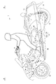
- FIG. 1 is a side view illustrating a schematic configuration of a motorcycle 1 according to a first embodiment.
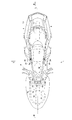
- FIG. 2 is a plan view showing a schematic configuration of the motorcycle 1.
- the motorcycle 1 includes a so-called underbone body frame 2.
- the vehicle body frame 2 includes a main frame 3 and a seat frame 4.
- the main frame 3 includes a head pipe 5, a frame body 6, and a front frame 7. Note that the main frame 3 may not include the front frame 7 depending on the type of the motorcycle 1.
- the vehicle body frame 2 is covered with a vehicle body cover 14.
- the front fork 8 is supported on the head pipe 5 so as to be swingable in the left-right direction via a steering shaft (not shown). That is, the front fork 8 is swingable in the left-right direction by inserting a steering shaft fixed to the upper end of the front fork 8 into the head pipe 5.
- a handle 9 is connected to the upper part of the steering shaft, and the front fork 8 swings by the operation of the handle 9.
- a front wheel 10 is rotatably attached to a lower end portion of the front fork 8.
- the engine unit 11 is attached to the rear part of the frame body 6.
- the engine unit 11 is a known unit swing engine in which an engine 11a and a transmission case 11b extending from the engine 11a to the left side of the rear wheel are united and suspended on a vehicle body so as to be swingable up and down.
- a transmission mechanism for transmitting the rotation of the engine to the rear wheels is adopted in the transmission case 11b, and a rear wheel output shaft (not shown) is located at the rear of the transmission case 11b.
- a rear wheel 12 is connected to the rear wheel output shaft.
- a seat 13 is provided above the engine 11a.
- the vehicle body cover 14 positioned between the engine unit 11 and the seat 13 in a side view extends rearward and upward of the engine unit 11 in a side view.
- the rear wheel 12 is disposed below the vehicle body cover 14.
- the rear part of the engine unit 11 is exposed to the outside.
- a fuel tank 30 is disposed in front of the engine 11a.
- the frame body 6 includes an upper frame 6a, a lower frame 6b, and a connection bracket 6c to which the rear ends are connected.
- the connecting bracket 6c has a middle structure (hollow structure) made of sheet metal.
- the upper frame 6a is a pair of left and right, and is welded to the side surface of the central portion of the head pipe 5 in the vertical direction, and extends rearwardly from there to the left and right.
- a pair of left and right lower frames 6b are also welded to the lower side surface of the head pipe 5 and extend rearwardly below the upper frame 6a with a space left and right.
- the lower frame 6b extends from the lower side to the upper side at the rear, and the rear end thereof is welded to the connection bracket 6c.
- the rear end portion of the upper frame 6a is welded to the connection bracket 6c.
- the front end portion of the seat frame 4 is welded to the connection bracket 6c.
- a part of the upper frame 6a is omitted from the broken line.
- the lower frame 6b overlaps the upper frame 6a in plan view, the rear portion is omitted from the handle 9 and is shown.
- reinforcing plates (gadgets) 15 are spread and welded to a plurality of locations in the front-rear direction.
- the reinforcing plate 15 is made of metal and reinforces the rigidity of the upper frame 6a and the lower frame 6b.
- a pivot shaft 28 that supports the engine unit 11 so as to be swingable in the vertical direction is provided at the rear portion of the connection bracket 6c.
- a rear cushion unit 29 is provided between the rear portion of the seat frame 4 and the transmission case 11b to cushion the swing of the engine unit 11.
- the front frame 7 includes an upper frame 7a, a lower frame 7b, and a connecting frame 7c.
- the upper frame 7a has a rectangular frame shape in plan view
- the lower frame 7b has a U-shape that opens rearward, and the two are connected to each other by two connecting frames 7c.
- the base end side of the upper frame 7a is bolted to the head pipe 5 via a bracket 17 provided at the center in the vehicle width direction.
- the left and right proximal end sides of the lower frame 7 b are bolted via the lower frame 6 b and the bracket 18 of the frame body 6.
- the bracket 18 is welded to the left and right lower frames 6b.
- the upper frame 7a is omitted.
- the battery 16 is supported on a cross member (not shown) spanned in the vehicle width direction of the lower frame 7b and accommodated inside the front frame 7.
- the battery 16 has a large number of electrode plates therein.
- An ECU 31 is installed in front of the battery 16.
- the engine 11a and the reinforcing plate 15 correspond to the metal structure in the present invention.
- the two antennas 20 and 21 are disposed outside the reinforcing plate 15 and the main frame 3 (frame body 6) in the vehicle width direction with the engine 11a interposed therebetween.
- the antennas 20 and 21 are installed facing each other across a center line L orthogonal to the width direction of the motorcycle 1.
- the antennas 20 and 21 are supported by the bracket 19.
- Each bracket 19 is attached to the reinforcing plate 15.
- the installation height of the antennas 20 and 21 is the same.
- the motorcycle 1 can perform road-to-vehicle communication with a roadside machine and vehicle-to-vehicle communication with other vehicles.
- a radio 27 connected to the antennas 20 and 21 is installed in front of the antennas 20 and 21. Note that the location of the wireless device is not limited to the front of the antenna.
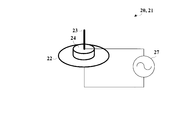
- FIGS. 3 and 4. are explanatory diagrams showing the configuration of the antenna.
- Antennas 20 and 21 are non-directional linear antennas. Examples of the omnidirectional linear antenna include a vertical dipole antenna and a brown antenna. In the first embodiment, a brown antenna is employed.
- the antennas 20 and 21 include a ground plane 22, a conductor rod 23, and an insulating portion 24 disposed between the ground plane 22 and the conductor rod 23.
- the wireless device 27 supplies power to the ground plane 22 and the conductor rod 23.
- ground plane 22 has a disk shape, three or more metal wires 26 (see FIG. 4) extending radially on the plane may be used instead of the ground plane 22.
- the ground plane 22 or the metal line 26 corresponds to the ground portion in the present invention.
- the conductor rod 23 is a radiating conductor that is erected upward from the insulating portion 24.
- the conductor rod 23 corresponds to the linear portion in the present invention.
- the insulating part 24 is a plate material made of fluororesin.
- the insulating part 24 may be made of other plastics or may be formed of other insulating materials.
- the radio 27 supplies high frequency power to the ground plane 22 or the metal wire 26 and the conductor rod 23.
- the overlapping of the conductor rod 23 and the metal structure in a side view is preferably two-thirds or more of the conductor rod 23, and more preferably all the conductor rods 23 are overlapped.
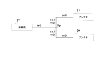
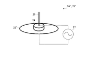
- FIG. 5 shows an antenna distributor using a quarter-wave transformer.
- the impedance from the wireless device 27 to the branch point Bp from the antennas 20 and 21 is 50 ⁇ .
- Each of the branch points Bp is connected to a 75 ⁇ wiring with a length of 1 ⁇ 4 wavelength (1 / 4 ⁇ ), and is further connected to the antennas 20 and 21 adjusted to 50 ⁇ through a 50 ⁇ wiring.
- coaxial power feeding can be easily performed. That is, the radio signal output from the wireless device 27 is distributed to the antennas 20 and 21 with the same phase.
- the two distribution circuits of the antennas 20 and 21 can be formed using a lumped constant matching circuit.
- a quarter-wave transformer is used, a coaxial line or a printed wiring board can be used, so that it can be easily mounted inside the motorcycle 1.
- the antenna distributor is not limited to this configuration, and other configurations may be adopted.
- the antenna branch can be arranged at the center of the vehicle body.
- the power supply line from the wireless device 27 to the branch point Bp can be made a short distance, and noise mixing and radio signal attenuation can be suppressed.
- the radio device 27 having a relatively heavy weight can be arranged at the center of the vehicle body, it is possible to suppress the deviation of the weight balance of the motorcycle 1.
- the radio wave traveling in the vehicle body inner direction is reflected by a metal structure such as the engine 11a and travels in the vehicle body outer direction.
- the radio wave traveling in the direction toward the outside of the vehicle body is interfered by the radio wave radiated from the antenna and the radio wave reflected by the metal structure, and the intensity of the radio wave varies depending on the position of the reception point.
- the communication distance in the horizontal direction may be shorter than that in the vertical direction, it does not matter that the radio waves in the horizontal direction become weak.
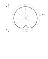
- FIG. 6 is an antenna characteristic diagram ideal for a motorcycle.
- the inter-vehicle communication with other vehicles in the lateral direction is such that a distance slightly longer than the road width is communicated.
- the antenna characteristic of the motorcycle 1 traveling on the road is preferably a radiation pattern Ep1 that is longer in the front-rear direction than in the width direction, as shown in FIG.
- the antenna characteristic when an omnidirectional antenna is installed in the front part of the vehicle body is deteriorated in the backward radiation characteristic due to the absorption and reflection of the passenger as shown in FIG. And the communication distance with the back becomes short.
- the communication distance to the front is shortened.
- FIG. 7 when only one antenna is arranged on the left side of the motorcycle 1, the communication distance of the other side of the motorcycle 1 (right side in FIG. 7) is absorbed or reflected by the motorcycle 1.
- Antennas 20 and 21 are installed at a distance D.
- the distance from the antenna 20 and the distance from the antenna 21 are both equal at L3. Therefore, since the phases of the radio waves from the antenna 20 and the antenna 21 at the reception point 1 are the same, the mutual radio waves strengthen each other.
- FIG. 9 shows a radiation pattern in the case where the antennas are arranged on the sides of the motorcycle 1 and there is no metal structure between the antennas.
- radio waves having the same phase are radiated from two antennas.
- this radiation pattern Ep3 at the reception points in the front-rear direction where the distances to the two antennas are almost the same, the radio waves from the respective antennas are combined in the same phase and thus emphasized.
- the waves are weakened because they are combined in opposite phases. .
- a position where the intensity of the radio wave is lowered depending on the distance and the angle is generated in the oblique direction.
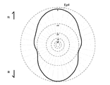
- the radiation pattern Ep4 according to the first embodiment can transmit radio waves strengthened in the front-rear direction by the two antennas 20 and 21 provided outside the main frame 3, and by a metal structure in the lateral direction. Mutual radio wave interference can be prevented. Thereby, it is possible to prevent the radio field intensity from being lowered in the oblique direction, and to obtain an elliptical radiation pattern having the major axis in the front-rear direction. Therefore, radio wave transmission / reception optimal for traveling of the motorcycle 1 can be performed.
- the installation heights of the two antennas 20 and 21 are the same, the distance difference between the radio waves in the front-rear direction can be further reduced. Thereby, favorable communication can be implemented.
- FIG. 11 and FIG. 11 and 12 are explanatory diagrams showing the configuration of the antenna in the second embodiment.
- the parts indicated by the same reference numerals as those in the first embodiment have the same configuration as in the first embodiment, and thus the description thereof is omitted here.
- the configurations of the motorcycle and the antenna other than those described below are the same as those in the first embodiment.
- the feature of the second embodiment is that the antenna disposed in the motorcycle 1 has directivity.
- the non-directional linear antenna is used in the first embodiment, the communication distance in the front-rear direction can be further extended by using the linear antenna having the directivity in the front-rear direction in the second embodiment.
- the antennas 20 ′ and 21 ′ in the second embodiment have a ground plane 22 ′ that extends in the front-rear direction of the vehicle (see FIG. 11). That is, the ground plane 22 'has an elliptical shape with the longitudinal axis of the vehicle as the major axis. Further, instead of using the elliptical ground plane 22 ', two metal wires 26' extending in the longitudinal direction of the vehicle may be used (see FIG. 12).
- the main frame 3 and the body cover It becomes easy to arrange
- positioning can be improved.
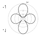
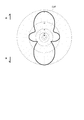
- FIG. 13 is an explanatory diagram showing antenna characteristics in the second embodiment. If it is a directional antenna in Example 2, as shown in FIG. 13, the antenna characteristic of the shape similar to the ideal antenna characteristic can be obtained.
- the radiation pattern Ep5 according to the second embodiment can obtain a radio wave characteristic in which the directivity in the front-rear direction is improved, although the intensity in the oblique direction is somewhat lower than that of the radiation pattern Ep4 according to the first embodiment.
- an elliptical radiation pattern having the major axis in the front-rear direction can be obtained, and radio waves that are optimal for traveling of the motorcycle 1 can be transmitted and received.
- the installation heights of the two antennas 20 ′ and 21 ′ are the same, the distance difference between the radio waves in the front-rear direction can be further reduced. Thereby, favorable communication can be implemented.
- the present invention is not limited to the above embodiment, and can be modified as follows.
- the two antennas 20 and 21 are disposed with the engine 11a interposed therebetween, but the present invention is not limited thereto. You may arrange
- the unit swing type engine unit 11 in which the engine 11a and the transmission case 11b are integrated is used, but other types of engine units may be employed.
- an engine unit of a type in which the rear wheel is suspended by a rear arm and the engine itself is fixed to the vehicle body may be employed.
- a mission case or the like may be used as a metal structure in addition to the cylinder, crankcase, and oil pan constituting the engine.
- each frame may be adopted as a part of the metal structure. In the frame alone, the overlapping area in the side view with the antennas 20 and 21 is insufficient, but the overlapping area in the side view with the antennas 20 and 21 may be secured by combination with other metal structures.
- an antenna having omnidirectionality or directivity in the front-rear direction is used as the antenna.
- the present invention is not limited to this. You may employ
- the cardioid recess may be arranged inward of the vehicle body.
- the motorcycle 1 is a scooter type vehicle having an underbone type frame, but is not limited thereto.
- frame types such as a backbone frame type and a diamond frame type may be adopted.
- the motorcycle 1 is not limited to the scooter type, but may be another type of motorcycle such as a naked type or a tourer type.
Abstract
Description
すなわち、従来の自動二輪車は、自車と他車との間の通信である車車間通信のうち、後方に位置する他車との通信には不利であるという問題がある。アンテナを搭乗者よりも前方のヘッドライト上に配置することで搭乗者による電波吸収の影響を低減させているとはいえ、搭乗者の吸収や反射の影響を無くすことはできない。また、二人乗りしている場合や、自動二輪車のタンデムシート後方に荷物を積載している場合は、電波の減衰や反射の影響が大きくなる。特に荷物を積載している場合、荷物の材質に相応した電波の吸収や反射も加わってより通信距離が短くなる。このような状態の電波の放射パターンEp6を図16に示す。放射パターンEp6では、後方の電波強度が低下している。
すなわち、本発明は、金属構造物が搭載されるメインフレームと前記メインフレームよりも後方に配置されるシートフレームとを有する車体フレームと、前記メインフレームより車幅方向外方に設けられた第1アンテナと、前記メインフレームと前記金属構造物のうち少なくとも前記金属構造物を挟んで前記第1アンテナと対向して配置される第2アンテナとを備え、前記第1アンテナおよび前記第2アンテナを用いて、路側機との路車間通信および他の車両との車車間通信を行う自動二輪車である。
図1および図2を参照する。図1は、実施例1に係る自動二輪車1の概略構成を示す側面図である。図2は自動二輪車1の概略構成を示す平面図である。自動二輪車1はいわゆるアンダーボーン型の車体フレーム2を備える。車体フレーム2はメインフレーム3とシートフレーム4とを備える。メインフレーム3は、ヘッドパイプ5と、フレーム本体6と、前フレーム7とから構成される。なお、自動二輪車1の種類によっては、メインフレーム3は前フレーム7を備えなくてもよい。車体フレーム2は車体カバー14に覆われている。
次に図3および図4を参照して自動二輪車1に備えられたアンテナの構成を説明する。図3および図4は、アンテナの構成を示す説明図である。
次に、従来のアンテナ特性および実施例1におけるアンテナ特性を説明する。図6は自動二輪車に理想のアンテナ特性図である。自動二輪車1において横方向の他の車両との車車間通信は、道路幅よりも少し長い距離を通信する程度である。しかしながら、前後方向の他の車両との車車間通信または、路側機との路車間通信の場合、他の車両との距離が長くなり、通信距離が長くなる傾向がある。そこで、道路を走行する自動二輪車1のアンテナ特性は、図6に示すように、幅方向よりも前後方向に長い放射パターンEp1が好ましい。
2 … 車体フレーム
3 … メインフレーム
4 … シートフレーム
5 … ヘッドパイプ
7 … 前フレーム
11a … エンジン
14 … 車体カバー
15 … 補強板
16 … バッテリ
20、20’、21、21’ … アンテナ
30 … 燃料タンク
31 …ECU
Claims (12)
- 金属構造物が搭載されるメインフレームと前記メインフレームよりも後方に配置されるシートフレームとを有する車体フレームと、
前記メインフレームより車幅方向外方に設けられた第1アンテナと、
前記メインフレームと前記金属構造物のうち少なくとも前記金属構造物を挟んで前記第1アンテナと対向して配置される第2アンテナとを備え、
前記第1アンテナおよび前記第2アンテナを用いて、路側機との路車間通信および他の車両との車車間通信を行う
自動二輪車。 - 請求項1に記載の自動二輪車において、
前記第1アンテナおよび前記第2アンテナは線状アンテナである
自動二輪車。 - 請求項1または2に記載の自動二輪車において、
前記第1アンテナおよび前記第2アンテナは前後方向に指向性を有する
自動二輪車。 - 請求項3に記載の自動二輪車において、
前記線状アンテナは、車幅方向よりも前後方向に長いグランド部と放射導体である線状部とを有するブラウンアンテナであり、
前記グランド部の前後方向の長さが前記線状部の長さより長い
自動二輪車。 - 請求項1から4のいずれか1つに記載の自動二輪車において、
前記メインフレームはヘッドパイプよりも前方に配置される前フレームを含む
自動二輪車。 - 請求項1から5のいずれか1つに記載の自動二輪車において、
前記金属構造物はエンジンユニットである
自動二輪車。 - 請求項1から5のいずれか1つに記載の自動二輪車において、
前記メインフレームは剛性を補強する補強板を備え、
前記金属構造物は補強板である
自動二輪車。 - 請求項1から5のいずれか1つに記載の自動二輪車において、
前記金属構造物は金属製の補機類である
自動二輪車。 - 請求項1から8のいずれか1つに記載の自動二輪車において、
前記第1アンテナおよび前記第2アンテナは走行姿勢の搭乗者の足と側面視で重ならないよう配置されている
自動二輪車。 - 請求項1から9のいずれか1つに記載の自動二輪車において、
前記第1アンテナおよび前記第2アンテナは前記メインフレームの少なくとも一部を覆うカバーと前記メインフレームとの間に配置されている
自動二輪車。 - 請求項1から10のいずれか1つに記載の自動二輪車において、
前記第1アンテナおよび前記第2アンテナは側面視で高さが同一に配置されている
自動二輪車。 - 請求項1から11のいずれか1つに記載の自動二輪車において、
前記第1アンテナおよび前記第2アンテナは側面視で前記メインフレームまたは前記エンジンと重なるように配置されている
自動二輪車。
Priority Applications (3)
| Application Number | Priority Date | Filing Date | Title |
|---|---|---|---|
| JP2015508441A JP6028090B2 (ja) | 2013-03-28 | 2014-03-20 | 自動二輪車 |
| US14/780,816 US10249942B2 (en) | 2013-03-28 | 2014-03-20 | Two-wheeled motor vehicle |
| EP14775908.8A EP2980920B1 (en) | 2013-03-28 | 2014-03-20 | Motorcycle |
Applications Claiming Priority (2)
| Application Number | Priority Date | Filing Date | Title |
|---|---|---|---|
| JP2013-068991 | 2013-03-28 | ||
| JP2013068991 | 2013-03-28 |
Publications (1)
| Publication Number | Publication Date |
|---|---|
| WO2014157011A1 true WO2014157011A1 (ja) | 2014-10-02 |
Family
ID=51623988
Family Applications (1)
| Application Number | Title | Priority Date | Filing Date |
|---|---|---|---|
| PCT/JP2014/057908 WO2014157011A1 (ja) | 2013-03-28 | 2014-03-20 | 自動二輪車 |
Country Status (4)
| Country | Link |
|---|---|
| US (1) | US10249942B2 (ja) |
| EP (1) | EP2980920B1 (ja) |
| JP (1) | JP6028090B2 (ja) |
| WO (1) | WO2014157011A1 (ja) |
Cited By (2)
| Publication number | Priority date | Publication date | Assignee | Title |
|---|---|---|---|---|
| JP2016075569A (ja) * | 2014-10-06 | 2016-05-12 | スズキ株式会社 | 通信装置及びこれを備えた車両 |
| JPWO2020045252A1 (ja) * | 2018-08-27 | 2021-08-12 | ヤマハ発動機株式会社 | V2x通信用アンテナ搭載リーン車両 |
Families Citing this family (2)
| Publication number | Priority date | Publication date | Assignee | Title |
|---|---|---|---|---|
| TW201902024A (zh) * | 2017-05-26 | 2019-01-01 | 銳鋒股份有限公司 | 行車電腦裝置 |
| DE112018007647T5 (de) * | 2018-05-23 | 2021-03-18 | Honda Motor Co., Ltd. | Grätschsitzfahrzeug |
Citations (4)
| Publication number | Priority date | Publication date | Assignee | Title |
|---|---|---|---|---|
| JPH0591003A (ja) * | 1991-09-25 | 1993-04-09 | Mazda Motor Corp | 車両用アンテナ装置 |
| JP2003309419A (ja) * | 2002-04-16 | 2003-10-31 | Nippon Dengyo Kosaku Co Ltd | グランドプレーンアンテナ |
| JP2008114654A (ja) * | 2006-11-01 | 2008-05-22 | Yamaha Motor Co Ltd | 自動二輪車 |
| JP4156783B2 (ja) | 2000-04-03 | 2008-09-24 | 本田技研工業株式会社 | 自動二輪車のアンテナ配置構造 |
Family Cites Families (13)
| Publication number | Priority date | Publication date | Assignee | Title |
|---|---|---|---|---|
| US2267266A (en) * | 1936-06-15 | 1941-12-23 | Edward C Baxley | Antenna system |
| US4658266A (en) * | 1983-10-13 | 1987-04-14 | Doty Archibald C Jun | Vertical antenna with improved artificial ground system |
| JPH05238438A (ja) * | 1992-02-28 | 1993-09-17 | Shizuo Kawai | 自動車、オートバイ等車輛の燃費向上方法 |
| EP1513299B1 (en) * | 2002-04-12 | 2009-06-10 | Honda Giken Kogyo Kabushiki Kaisha | Vehicle intercommunication apparatus |
| JP3793129B2 (ja) * | 2002-08-30 | 2006-07-05 | 川崎重工業株式会社 | 自動二輪車の車体フレーム |
| JP4005883B2 (ja) * | 2002-09-13 | 2007-11-14 | ヤマハ発動機株式会社 | 自動二輪車のリヤアーム |
| US7230545B2 (en) * | 2003-11-07 | 2007-06-12 | Nattel Group, Inc. | Automobile communication and registry system |
| JP2005234921A (ja) | 2004-02-20 | 2005-09-02 | Honda Motor Co Ltd | 車車間通信装置 |
| JP2006199168A (ja) * | 2005-01-21 | 2006-08-03 | Kawasaki Heavy Ind Ltd | レジャービィークルの盗難防止装置 |
| JP5158964B2 (ja) * | 2008-09-30 | 2013-03-06 | 本田技研工業株式会社 | 自動二輪車のナビゲーション装置 |
| JP2010120626A (ja) * | 2008-10-24 | 2010-06-03 | Yamaha Motor Co Ltd | 自動二輪車 |
| JP2010120627A (ja) * | 2008-10-24 | 2010-06-03 | Yamaha Motor Co Ltd | 自動二輪車 |
| JP5427735B2 (ja) * | 2010-08-31 | 2014-02-26 | 本田技研工業株式会社 | 鞍乗り型車両 |
-
2014
- 2014-03-20 JP JP2015508441A patent/JP6028090B2/ja active Active
- 2014-03-20 EP EP14775908.8A patent/EP2980920B1/en active Active
- 2014-03-20 WO PCT/JP2014/057908 patent/WO2014157011A1/ja active Application Filing
- 2014-03-20 US US14/780,816 patent/US10249942B2/en active Active
Patent Citations (4)
| Publication number | Priority date | Publication date | Assignee | Title |
|---|---|---|---|---|
| JPH0591003A (ja) * | 1991-09-25 | 1993-04-09 | Mazda Motor Corp | 車両用アンテナ装置 |
| JP4156783B2 (ja) | 2000-04-03 | 2008-09-24 | 本田技研工業株式会社 | 自動二輪車のアンテナ配置構造 |
| JP2003309419A (ja) * | 2002-04-16 | 2003-10-31 | Nippon Dengyo Kosaku Co Ltd | グランドプレーンアンテナ |
| JP2008114654A (ja) * | 2006-11-01 | 2008-05-22 | Yamaha Motor Co Ltd | 自動二輪車 |
Non-Patent Citations (1)
| Title |
|---|
| See also references of EP2980920A4 * |
Cited By (4)
| Publication number | Priority date | Publication date | Assignee | Title |
|---|---|---|---|---|
| JP2016075569A (ja) * | 2014-10-06 | 2016-05-12 | スズキ株式会社 | 通信装置及びこれを備えた車両 |
| JPWO2020045252A1 (ja) * | 2018-08-27 | 2021-08-12 | ヤマハ発動機株式会社 | V2x通信用アンテナ搭載リーン車両 |
| JP7125213B2 (ja) | 2018-08-27 | 2022-08-24 | ヤマハ発動機株式会社 | V2x通信用アンテナ搭載リーン車両 |
| US11909106B2 (en) | 2018-08-27 | 2024-02-20 | Yamaha Hatsudoki Kabushiki Kaisha | V2X communication antenna-mounted leaning vehicle |
Also Published As
| Publication number | Publication date |
|---|---|
| JPWO2014157011A1 (ja) | 2017-02-16 |
| EP2980920A4 (en) | 2016-03-23 |
| EP2980920B1 (en) | 2017-06-28 |
| US10249942B2 (en) | 2019-04-02 |
| JP6028090B2 (ja) | 2016-11-16 |
| EP2980920A1 (en) | 2016-02-03 |
| US20160043462A1 (en) | 2016-02-11 |
Similar Documents
| Publication | Publication Date | Title |
|---|---|---|
| JP6007311B2 (ja) | 自動二輪車 | |
| JP6028090B2 (ja) | 自動二輪車 | |
| US11909106B2 (en) | V2X communication antenna-mounted leaning vehicle | |
| JP5602979B1 (ja) | 車両 | |
| JP5620034B1 (ja) | 車両 | |
| JP4193837B2 (ja) | トレーリング・アーム式サスペンション構造及びアクスルキャリア | |
| CN112119005B (zh) | 跨骑型车辆 | |
| US20210203063A1 (en) | Straddle type vehicle | |
| WO2019224959A1 (ja) | 鞍乗型車両 | |
| JP6346292B2 (ja) | 鞍乗型車両 | |
| KR101698030B1 (ko) | 안테나 | |
| CN104827926B (zh) | 电动车及用于电动车的电池箱固定组件 | |
| JP6217367B2 (ja) | 車両のルーフ構造 | |
| JP7191963B2 (ja) | 車車間通信用アンテナ搭載リーン車両、及びリーン車両に搭載されるように構成された車車間通信用アンテナ | |
| JP7183279B2 (ja) | 車車間通信用アンテナ搭載リーン車両、及びリーン車両に搭載されるように構成された車車間通信用アンテナ | |
| JP2007064730A (ja) | 車載用レーダー装置 | |
| CN216887086U (zh) | 车体组件和具有其的代步车 | |
| JPWO2020045390A1 (ja) | 車車間通信用アンテナ搭載リーン車両 | |
| JP5845821B2 (ja) | タイヤ状態検出装置用アンテナシステム |
Legal Events
| Date | Code | Title | Description |
|---|---|---|---|
| 121 | Ep: the epo has been informed by wipo that ep was designated in this application |
Ref document number: 14775908 Country of ref document: EP Kind code of ref document: A1 |
|
| ENP | Entry into the national phase |
Ref document number: 2015508441 Country of ref document: JP Kind code of ref document: A |
|
| NENP | Non-entry into the national phase |
Ref country code: DE |
|
| WWE | Wipo information: entry into national phase |
Ref document number: 14780816 Country of ref document: US |
|
| REEP | Request for entry into the european phase |
Ref document number: 2014775908 Country of ref document: EP |
|
| WWE | Wipo information: entry into national phase |
Ref document number: 2014775908 Country of ref document: EP |