EP2980920B1 - Motorcycle - Google Patents
Motorcycle Download PDFInfo
- Publication number
- EP2980920B1 EP2980920B1 EP14775908.8A EP14775908A EP2980920B1 EP 2980920 B1 EP2980920 B1 EP 2980920B1 EP 14775908 A EP14775908 A EP 14775908A EP 2980920 B1 EP2980920 B1 EP 2980920B1
- Authority
- EP
- European Patent Office
- Prior art keywords
- antenna
- motor vehicle
- wheeled motor
- main frame
- vehicle
- Prior art date
- Legal status (The legal status is an assumption and is not a legal conclusion. Google has not performed a legal analysis and makes no representation as to the accuracy of the status listed.)
- Active
Links
Images


Classifications
-
- B—PERFORMING OPERATIONS; TRANSPORTING
- B62—LAND VEHICLES FOR TRAVELLING OTHERWISE THAN ON RAILS
- B62J—CYCLE SADDLES OR SEATS; AUXILIARY DEVICES OR ACCESSORIES SPECIALLY ADAPTED TO CYCLES AND NOT OTHERWISE PROVIDED FOR, e.g. ARTICLE CARRIERS OR CYCLE PROTECTORS
- B62J43/00—Arrangements of batteries
- B62J43/20—Arrangements of batteries characterised by the mounting
-
- B—PERFORMING OPERATIONS; TRANSPORTING
- B62—LAND VEHICLES FOR TRAVELLING OTHERWISE THAN ON RAILS
- B62K—CYCLES; CYCLE FRAMES; CYCLE STEERING DEVICES; RIDER-OPERATED TERMINAL CONTROLS SPECIALLY ADAPTED FOR CYCLES; CYCLE AXLE SUSPENSIONS; CYCLE SIDE-CARS, FORECARS, OR THE LIKE
- B62K11/00—Motorcycles, engine-assisted cycles or motor scooters with one or two wheels
- B62K11/02—Frames
- B62K11/04—Frames characterised by the engine being between front and rear wheels
-
- B—PERFORMING OPERATIONS; TRANSPORTING
- B62—LAND VEHICLES FOR TRAVELLING OTHERWISE THAN ON RAILS
- B62K—CYCLES; CYCLE FRAMES; CYCLE STEERING DEVICES; RIDER-OPERATED TERMINAL CONTROLS SPECIALLY ADAPTED FOR CYCLES; CYCLE AXLE SUSPENSIONS; CYCLE SIDE-CARS, FORECARS, OR THE LIKE
- B62K19/00—Cycle frames
- B62K19/30—Frame parts shaped to receive other cycle parts or accessories
- B62K19/40—Frame parts shaped to receive other cycle parts or accessories for attaching accessories, e.g. article carriers, lamps
-
- H—ELECTRICITY
- H01—ELECTRIC ELEMENTS
- H01Q—ANTENNAS, i.e. RADIO AERIALS
- H01Q1/00—Details of, or arrangements associated with, antennas
- H01Q1/27—Adaptation for use in or on movable bodies
- H01Q1/32—Adaptation for use in or on road or rail vehicles
- H01Q1/3208—Adaptation for use in or on road or rail vehicles characterised by the application wherein the antenna is used
- H01Q1/3233—Adaptation for use in or on road or rail vehicles characterised by the application wherein the antenna is used particular used as part of a sensor or in a security system, e.g. for automotive radar, navigation systems
-
- H—ELECTRICITY
- H01—ELECTRIC ELEMENTS
- H01Q—ANTENNAS, i.e. RADIO AERIALS
- H01Q1/00—Details of, or arrangements associated with, antennas
- H01Q1/27—Adaptation for use in or on movable bodies
- H01Q1/32—Adaptation for use in or on road or rail vehicles
- H01Q1/325—Adaptation for use in or on road or rail vehicles characterised by the location of the antenna on the vehicle
- H01Q1/3283—Adaptation for use in or on road or rail vehicles characterised by the location of the antenna on the vehicle side-mounted antennas, e.g. bumper-mounted, door-mounted
-
- H—ELECTRICITY
- H01—ELECTRIC ELEMENTS
- H01Q—ANTENNAS, i.e. RADIO AERIALS
- H01Q1/00—Details of, or arrangements associated with, antennas
- H01Q1/48—Earthing means; Earth screens; Counterpoises
-
- H—ELECTRICITY
- H01—ELECTRIC ELEMENTS
- H01Q—ANTENNAS, i.e. RADIO AERIALS
- H01Q21/00—Antenna arrays or systems
- H01Q21/06—Arrays of individually energised antenna units similarly polarised and spaced apart
- H01Q21/08—Arrays of individually energised antenna units similarly polarised and spaced apart the units being spaced along or adjacent to a rectilinear path
-
- H—ELECTRICITY
- H01—ELECTRIC ELEMENTS
- H01Q—ANTENNAS, i.e. RADIO AERIALS
- H01Q21/00—Antenna arrays or systems
- H01Q21/29—Combinations of different interacting antenna units for giving a desired directional characteristic
-
- H—ELECTRICITY
- H01—ELECTRIC ELEMENTS
- H01Q—ANTENNAS, i.e. RADIO AERIALS
- H01Q9/00—Electrically-short antennas having dimensions not more than twice the operating wavelength and consisting of conductive active radiating elements
- H01Q9/04—Resonant antennas
- H01Q9/30—Resonant antennas with feed to end of elongated active element, e.g. unipole
- H01Q9/32—Vertical arrangement of element
- H01Q9/38—Vertical arrangement of element with counterpoise
Definitions
- the present invention relates to a two-wheeled motor vehicle. More particularly, the present invention is directed to a two-wheeled motor vehicle provided with antennas for road-to-vehicle communications and vehicle-to-vehicle communications.
- two-wheeled motor vehicles have been developed for performing communications specified in ASV (Advanced Safety Vehicle) using IT (Information Technology), which is a part of ITS (Intelligent Transport System).
- Examples of such two-wheeled motor vehicles include a vehicle having an antenna disposed forward of the vehicle for performing communications with front vehicles or roadside units. See, for example, Japanese Patent No. 4156783 (also published as EP 1 143 259 A2 ).
- a non-directional antenna is disposed forward of an inclined line extending between the middle of a bar handle and an axle of a front wheel. This prevents influences of electromagnetic wave absorption by the rider's body, and prevents reductions in electromagnetic fields in vertical and horizontal directions.
- EP 1 690 761 A2 describes a theft prevention apparatus of a motorcycle including directional antennae mounted to mounting portions of back mirrors on both sides of a front cowling of the motorcycle.
- the antennae are each capable of sending and receiving a radio wave to/from an overlapping region rearward from the antennae such that the respective antennae cover a rider's seat.
- the currently-used example with such a configuration has the following drawbacks.
- the currently-used two-wheeled motor vehicle has a disadvantage for vehicle-to-vehicle communications between the rider's own vehicle and rearward vehicles among other vehicles.
- the influences of electromagnetic wave absorption by the rider is decreased with the antenna disposed on a head light forward of the rider, it is impossible to eliminate the influence of absorption or reflection by the rider.
- the influence of electromagnetic wave attenuation or reflection increases upon riding double or with a load rearward of a tandem seat of the two-wheeled motor vehicle.
- a communication distance becomes shorter due to additional electromagnetic wave absorption or reflection corresponding to materials of the load.
- Figure 16 illustrates an emission pattern Ep6 of electromagnetic waves under such a condition.
- the emission pattern Ep6 includes a rearward portion with degraded electromagnetic wave intensities.
- the present invention has been made in view of the state of the art noted above, and one of its objects is to provide a two-wheeled motor vehicle that allows suitable communications with side vehicles and roadside units as well as suitable vehicle-to-vehicle communications with forward and rearward vehicles.
- the present invention is constituted as stated below to achieve the above object.
- the present invention provides a two-wheeled motor vehicle.
- the two-wheeled motor vehicle includes a vehicle body frame with a main frame on which a metal structure is mounted and a seat frame disposed at a rearward position of the main frame, a first antenna disposed outside the main frame in a vehicle width direction, and a second antenna opposite to the first antenna across at least the metal structure among the main frame and the metal structure.
- the two-wheeled motor vehicle performs road-to-vehicle communications with roadside units and vehicle-to-vehicle communications with other vehicles using the first antenna and the second antenna.
- the first and second antennas are disposed outside the main frame across the metal structure or the metal structure and the main frame. This causes the electromagnetic waves from the first antenna to the second antenna to be reflected by the main frame or the metal structure mounted on the main frame. The electromagnetic waves from the second antenna to the first antenna are reflected in the same manner. Consequently, the electromagnetic waves from the first antenna and from the second antenna are not received simultaneously in transverse and oblique directions of the vehicle, allowing elimination of interference of the electromagnetic waves.
- the first antenna faces to the second antenna across the metal structure. This reduces a difference in distance between the first antenna and the second antenna and a receiving point of the electromagnetic waves travelling forward/rearward. Consequently, the electromagnetic waves from both antennas reach the receiving point in substantially the same phase, leading to a slight variation in electric field intensity. It is therefore possible to perform road-to-vehicle communications and vehicle-to-vehicle communications in the longitudinal, traverse, and oblique directions of the vehicle.
- the first antenna and the second antenna are each a linear antenna. Using the linear antenna allows the road-to-vehicle communications and the vehicle-to-vehicle communications at low prices.
- the main frame includes a front frame disposed at a forward position of a head tube.
- the metal structure reflecting the electromagnetics wave is disposed within an area enclosed with the front frame, the electromagnetic waves from both the first antenna and the second antenna are received only in the longitudinal direction of the vehicle body.
- the first antenna and the second antenna can be disposed forward of the head tube. This enhances arrangement flexibility of the antennas.
- the metal structure is an engine unit.
- the first antenna and the second antenna are disposed across the engine unit, allowing elimination of the interference of the electromagnetic waves in the traverse and oblique directions of the vehicle.
- the main frame includes a reinforcing board reinforcing rigidity of the main frame.
- the metal structure may be the reinforcing board.
- the first antenna and the second antenna are disposed across the reinforcing board, allowing elimination of the interference of the electromagnetic waves in the traverse and oblique directions of the vehicle.
- the metal structure may be metal accessories.
- the first antenna and the second antenna are disposed across the metal accessories, allowing elimination of the interference of the electromagnetic waves in the traverse and oblique directions of the vehicle.
- first antenna and the second antenna do not overlap rider's feet in a travelling attitude in side view.
- the first antenna and the second antenna do not overlap the rider's feet in the traveling attitude in side view. This prevents the rider's feet from absorbing the electromagnetic waves emitted from the first antenna and the second antenna.
- first antenna and the second antenna are disposed between a cover and the main frame, the cover covering at least a part of the main frame. This allows attachment of the cover after assembling the first antenna and the second antenna, enhancing efficiency in assembly work.
- first antenna and the second antenna are disposed at the same level in side view.
- the first antenna and the second antenna are disposed at the same level, achieving reduction in distance difference of the electromagnetic waves between the receiving point and the antennas in the forward/rearward direction. Consequently, satisfactory communications are obtainable.
- the first antenna and the second antenna overlap the main frame or the engine in side view. Consequently, the electromagnetic waves spreading from the antennas toward the middle of the vehicle are reflected on the main frame or the engine, whereby only the electromagnetic waves only reflected from either the first or second antenna are received in the traverse and oblique directions. This allows elimination of a variation in intensity of the electromagnetic waves due to the interference.
- the two-wheeled motor vehicle allows suitable communications with the side vehicles and the roadside units as well as suitable vehicle-to-vehicle communications with forward and rearward vehicles.
- a scooter-type two-wheeled motor vehicle is to be described as one example of a two-wheeled motor vehicle in the present invention.
- "front,” “rear,” “right” and “left” are based on a traveling direction of the two-wheeled motor vehicle.
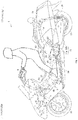
- Figure 1 is a side view illustrating an outline construction of a two-wheeled motor vehicle 1 according to Embodiment 1.
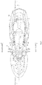
- Figure 2 is a plan view illustrating the outline construction of the two-wheeled motor vehicle 1.
- the two-wheeled motor vehicle 1 includes a so-called underbone-type vehicle body frame 2.
- the vehicle body frame 2 includes a main frame 3 and a seat frame 4.
- the main frame 3 is formed by a head tube 5, a frame main body 6, and a front frame 7.
- the main frame 3 does not necessarily include the front frame 7 depending on the type of the two-wheeled motor vehicles 1.
- the vehicle body frame 2 is covered with a vehicle body cover 14.
- Front forks 8 are supported on the head tube 5 via a steering shaft, not shown, and are swingable in right and left directions. That is, the front forks 8 are swingable in the right and left directions by inserting a steering shaft fixed on upper ends of the front forks 8 into the head tube 5.
- a handle bar 9 is connected to an upper part of the steering shaft. Operation of the handle bar 9 causes the front forks 8 to swing.
- a front wheel 10 is rotatably attached to lower ends of the front forks 8.
- the engine unit 11 is attached rearward of the frame main body 6.
- the engine unit 11 is a well-known unit swing engine.
- the engine unit 11 includes an engine 11a and a transmission case 11b extending leftward from the engine 11a toward the rear wheel.
- the engine 11a and the transmission case 11b are integrated with each other to be suspended on the vehicle body vertically and swingably.
- the transmission case 11b accommodates a transmission mechanism for transmitting engine rotation to the rear wheel.
- a rear wheel output shaft, not shown, is located rearward of the transmission case 11b.
- the rear wheel 12 is connected to the rear wheel output shaft.
- a seat 13 is provided above the engine 11a.
- the vehicle body cover 14 between the engine unit 11 and the seat 13 in side view extends rearward and above of the engine unit 11 in side view.
- the rear wheel 12 is disposed below the vehicle body cover 14.
- a rear part of the engine unit 11 is exposed externally.
- a fuel tank 30 is provided forward of the engine 11a.
- the frame main body 6 includes an upper frame 6a, a lower frame 6b, and a connection bracket 6c to which rear ends of the upper and lower frames 6a and 6b are connected.
- the connection bracket 6c is made of a sheet metal, and has a hollow structure (twin-half-shell structure).
- the upper frame 6a is composed of paired right and left upper frame portions, and the portions are welded on the side surface of the head tube 5 in the middle portion thereof in vertical direction, from which the portions extend rearward apart from each other rightward and leftward.
- the lower frame 6b is composed of paired right and left lower frame portions, and the portions are welded on the side surface of the head tube 5 in the lower portion thereof, from which the portions extend rearward below the upper frames 6a apart from each other rightward and leftward.
- the lower frame 6b extends upward on the rearward portion thereof, and the rear end thereof is welded on the connection bracket 6c.
- the rear end face of the upper frame 6a is welded on the connection bracket 6c.
- the front end face of the seat frame 4 is welded on the connection bracket 6c.
- Figure 2 partially illustrates the upper frame 6a omitted by break lines.
- the lower frame 6b overlaps the upper frame 6a in the plan view, and accordingly, a portion rearward of the handle bar 9 is omitted.
- a reinforcing board (gusset) 15 is suspended dispersedly and is welded at a plurality of positions between the upper frame 6a and the lower frame 6b in the forward/rearward direction.
- the reinforcing board 15 is made of metal, and reinforces the rigidity of the upper frame 6a and the lower frame 6b.
- a pivot shaft 28 is disposed rearward of the connection bracket 6c for holding the engine unit 11 so as to oscillate vertically.
- a rear cushion unit 29 is disposed between the rear portion of the seat frame 4 and the transmission case 11b for cushion of oscillation of the engine unit 11.
- the front frame 7 includes an upper frame 7a, a lower frame 7b, and a connection frame 7c.
- the upper frame 7a is rectangular when seen in plan view.
- the lower frame 7b is in a U-shape having an opening directed rearward. Both of the frames are connected via the connection frame 7c at two right and left positions.
- the proximal end face of the upper frame 7a is bolted to the head tube 5 via a bracket 17 provided in the middle of the vehicle width.
- right and left proximal end faces of the lower frame 7b are bolted via the lower frame 6b of the frame main body 6 and a bracket 18.
- the bracket 18 is welded on the right and left lower frames 6b.
- the upper frame 7a is omitted.
- a battery 16 is held on a cross member (not shown) suspended over the lower frame 7b in the vehicle width direction, and is accommodated in the front frame 7.
- the battery 16 includes multiple electrode plates inside thereof.
- An ECU 31 is disposed forward of the battery 16.
- the engine 11a and the reinforcing board 15 correspond to the metal structure in the present invention.
- Two antennas 20 and 21 are disposed across the engine 11 a outside the reinforcing board 15 and the main frame 3 (frame main body 6) in the vehicle width direction.
- the antennas 20 and 21 face to each other across the center line L orthogonal to the width direction of the two-wheeled motor vehicle 1.
- the antennas 20 and 21 are held with brackets 19 individually. Each of the brackets 19 is attached to the reinforcing board 15.
- the antennas 20 and 21 are disposed at the same level.
- the antennas 20 and 21 allow the two-wheeled motor vehicle 1 to perform road-to-vehicle communications with the roadside units and vehicle-to-vehicle communications with other vehicles.
- a radio equipment 27 for connecting to the antennas 20 and 21 is disposed forward of the antennas 20 and 21. Here, the radio equipment is not necessarily disposed forward of the antennas.
- Figures 3 and 4 each illustrate a configuration of the antennas.
- the antennas 20 and 21 are each a non-directional linear antenna.
- Examples of the non-directional linear antenna include a vertical dipole antenna and a Brown antenna.
- a Brown antenna is adopted.
- the antennas 20 and 21 each include a ground plane 22, a conductor rod 23, and an insulation member 24.
- the insulation member 24 is provided between the ground plane 22 and the conductor rod 23.
- the radio equipment 27 supplies power to the ground plane 22 and the conductor rod 23.
- the ground plane 22 is in a disk shape. Alternatively, instead of the disk ground plane 22, three or more metal wires 26 extending radially on a plane may be adopted. See Figure 4 .
- the ground plane 22 or the metal wires 26 corresponds to the ground in the present invention.
- the conductor rod 23 is a radiation conductor erected upward from the insulation member 24.
- the conductor rod 23 corresponds to the linear unit in the present invention.
- the insulation member 24 is a plate made of a fluorine resin.
- the insulation member 24 may be made of other materials such as plastic, or may be formed by other insulating materials.
- the radio equipment 27 supplies high-frequency power to the ground plane 22 or the metal wires 26 as well as the conductor rod 23.
- conductor rod 23 it is preferred that two-thirds or more of the conductor rod 23 overlaps the metal structure in side view, and it is more preferred that the entire conductor rod 23 overlaps the metal structure in side view.
- Figure 5 illustrates an antenna distributor with a 1/4-wavelength transformer. It is assumed that impedance from the radio equipment 27 to a bifurcation point Bp to the antennas 20 and 21 is 50 ⁇ . Then the radio equipment 27 is connected to wires of 75 ⁇ by a 1/4 wavelength (1/4 ⁇ ) at the bifurcation point Bp, and is connected via wires of 50 ⁇ to the antennas 20 and 21 individually adjusted to be of 50 ⁇ . Such a configuration facilitates coaxial feeding. That is, an electromagnetic wave signal from the radio equipment 27 is distributed to the antennas 20 and 21 at the same phase. Such two distribution circuits for the antennas 20 and 21 can each be formed with a lumped constant matching circuit. With the 1/4-wavelength transformer, a coaxial line or a printed wiring board is usable, leading to easy install of the antennas within the two-wheeled motor vehicle 1.
- the antenna distributor is not limited to this configuration, and may adopt other configurations.
- the antennas 20 and 21 are disposed in the middle of the vehicle body of the two-wheeled motor vehicle 1, whereby the antenna bifurcation can be disposed in the middle of the vehicle body. Accordingly, a power feeder from the radio equipment 27 to the bifurcation point Bp can be made short, leading to suppression in noise entering and in attenuation of electromagnetic wave signals. Moreover, the radio equipment 27 with a relatively sufficient weight can be disposed in the middle of the vehicle body, achieving suppression in weight unbalance of the two-wheeled motor vehicle 1.
- An electromagnetic wave among the electromagnetic waves from the antennas 20 and 21 towards the inside of the vehicle body reflects on the metal structure such as the engine 11a to travel toward outside of the vehicle body. Consequently, the electromagnetic wave traveling toward the outside of the vehicle body is brought into interference with the electromagnetic waves from the antennas and reflected on the metal structure. This causes various intensities of the electromagnetic waves depending on receiving positions. However, since a communication distance in the traverse direction may be shorter than that in the forward/rearward direction, a low intensity of the electromagnetic waves in the traverse direction is not problematic.
- Figure 6 illustrates a property of the antenna ideal for the two-wheeled motor vehicle.
- the vehicle-to-vehicle communications with other vehicles in the traverse direction are performed at a communication distance a little longer than a road width.
- the vehicle-to-vehicle communications with other forward/rearward vehicles or the road-vehicle communications with the roadside units are performed at long distances to the other vehicles. Accordingly, a communication distance is likely to be long.
- the property of the antennas for the two-wheeled motor vehicle 1 travelling on the road is an emission pattern Ep1 having a length longer in the forward/rearward direction than in the width direction.
- Figure 16 illustrates a property of the non-directional antennas disposed on an anterior part of the vehicle body.
- a rearward emission property is degraded due to the influence of absorption or reflection by the rider, leading to a short communication distance to the rearward vehicle.
- a communication distance to the forward vehicle becomes short.
- an emission pattern Ep2 is generated that has a shorter communication distance to the other side (the right side in Figure 7 ) of the two-wheeled motor vehicle 1 due to absorption or reflection of the two-wheeled motor vehicle 1. That is, a right recess in the radial pattern Ep2 corresponds to the middle line L of the two-wheeled motor vehicle 1. Consequently, the electromagnetic waves rightward from the middle line L have low intensities.
- the antennas 20 and 21 are disposed at a distance D.
- a distance from the antenna 20 is equal to a distance from the antenna 21, and both are denoted by L3. Consequently, the electromagnetic waves at the receiving point 1 from the antenna 20 and the antenna 21 are in the same phase. This causes the electromagnetic waves to be intensified mutually.
- a distance L1 from the antenna 20 differs from a distance L2 from the antenna 21 by a difference (L2 - L1).
- the distance difference (L2 - L1) is an even multiple of ⁇ /2 ( ⁇ : a wavelength of the electromagnetic wave)
- the electromagnetic waves are in the same phase and are intensified mutually.
- the intensity of the electromagnetic wave at the receiving point P1 is equal to that at the receiving point P2.
- the distance difference (L2 - L1) is an odd multiple of ⁇ /2 ( ⁇ : a wavelength of the electromagnetic wave), the electromagnetic waves are in an antiphase relationship, and are weakened mutually.
- the receiving point P2 has degraded reception electric field intensity.
- Figure 9 illustrates an emission pattern in which the antennas are disposed on both sides of the two-wheeled motor vehicle 1 and no metal structure is present between the antennas.
- the electromagnetic waves in the same phase are emitted from the two antennas.
- Ep3 at a forward/rearward receiving point at which the distances from the two antennas are substantially equal to each other, the electromagnetic waves from the antennas are combined at the same phase, and thus are highlighted.
- the distances from the two antennas differ largely as the receiving point is shifted obliquely.
- the electromagnetic waves are combined in the antiphase. This causes degraded electromagnetic waves.
- a position may be generated in the oblique direction in which the electromagnetic wave has a low intensity due to the distance and an angle relative to the antennas.
- the electromagnetic waves in the traverse direction are combined by the phase difference determined from a distance between the two antennas.
- the two antennas are disposed at a distance D having an interval of 1 wavelength. Accordingly, the electromagnetic waves are combined at the same phase and intensified mutually.
- a point may be generated depending on the position of the receiving point in which a difference in distance from the first antenna and the second antenna is an odd multiple of a 1/2 wavelength. At this point, the electromagnetic waves are degraded.
- satisfied communications are performable with the forward/rearward vehicles and the side vehicles.
- unstable communications are performed with the vehicles in the oblique direction.
- the arrangement of the antennas in Embodiment 1 achieves the same antenna property as the ideal antenna property as illustrated in Figure 10 .
- the antennas 20 and 21 outside the main frame 3 allows transmission of the electromagnetic waves intensified mutually in the forward/rearward direction.
- the metal structure allows prevention of interference of the electromagnetic waves in the traverse direction. This allows prevention of degradation in intensity of the electromagnetic waves in the oblique direction, and thus obtains an oval emission pattern having a forward/rearward long axis. As a result, the electromagnetic waves suitable for traveling of the two-wheeled motor vehicle 1 can be transmitted and received.
- the two antennas 20 and 21 are disposed at the same level, leading to a reduced distance difference of the electromagnetic waves in the forward/rearward direction. This achieves satisfied communications.
- Figures 11 and 12 each illustrate a configuration of antennas according to Embodiment 2.
- the elements denoted by the same numerals as in Embodiment 1 are common to the elements in Embodiment 1, and thus the description thereof is to be omitted.
- the configurations of the two-wheeled motor vehicle and the antennas other than the following are common to the configurations in Embodiment 1.
- Embodiment 2 has the characteristic in that the antennas disposed in the two-wheeled motor vehicle 1 each have directionality. In Embodiment 1, the non-directional linear antennas are used. In contrast, in Embodiment 2, linear antennas having forward/rearward directionality are used, achieving a longer communication distance in the forward/rearward direction.
- Antennas 20' and 21' in Embodiment 2 each include a ground plane 22' extending in the longitudinal direction of the vehicle. See Figure 11 . That is, the ground plane 22' is oval having a long axis in the longitudinal direction of the vehicle. Instead of the oval ground plane 22', two metal wires 26' extending in the longitudinal direction of the vehicle may be used. See Figure 12 .
- ground board (ground plane 22', metal wire 26') extending in the longitudinal direction of the vehicle is used, achieving reduction in length of the ground board in the vehicle width direction. Consequently, the antennas are readily disposed in a narrow space between the main frame 3 and the vehicle body cover 14, leading to enhanced arrangement flexibility.
- FIG. 13 illustrates the antenna property in Embodiment 2.
- a directionality antenna in Embodiment 2 achieves an antenna property similar to the ideal antenna property as illustrated in Figure 13 .
- An emission pattern Ep5 in Embodiment 2 can obtain an electromagnetic wave property having enhanced forward/rearward directionality although the electromagnetic wave has a lower intensity in the oblique direction than the emission pattern Ep4 in Embodiment 1. Consequently, an oval emission pattern is obtainable having a long axis in the forward/rearward direction.
- the electromagnetic waves suitable for traveling of the two-wheeled motor vehicle 1 can be transmitted and received.
- the two antenna 20' and 21' are disposed at the same level, a distance difference of the electromagnetic waves in the forward/rearward direction can be decreased. This allows sufficient communications.
Description
- The present invention relates to a two-wheeled motor vehicle. More particularly, the present invention is directed to a two-wheeled motor vehicle provided with antennas for road-to-vehicle communications and vehicle-to-vehicle communications.
- In recent years, two-wheeled motor vehicles have been developed for performing communications specified in ASV (Advanced Safety Vehicle) using IT (Information Technology), which is a part of ITS (Intelligent Transport System). Examples of such two-wheeled motor vehicles include a vehicle having an antenna disposed forward of the vehicle for performing communications with front vehicles or roadside units. See, for example, Japanese Patent No.
4156783 EP 1 143 259 A2 -
EP 1 690 761 A2 - However, the currently-used example with such a configuration has the following drawbacks. The currently-used two-wheeled motor vehicle has a disadvantage for vehicle-to-vehicle communications between the rider's own vehicle and rearward vehicles among other vehicles. Although the influences of electromagnetic wave absorption by the rider is decreased with the antenna disposed on a head light forward of the rider, it is impossible to eliminate the influence of absorption or reflection by the rider. Moreover, the influence of electromagnetic wave attenuation or reflection increases upon riding double or with a load rearward of a tandem seat of the two-wheeled motor vehicle. Especially, with a load, a communication distance becomes shorter due to additional electromagnetic wave absorption or reflection corresponding to materials of the load.
Figure 16 illustrates an emission pattern Ep6 of electromagnetic waves under such a condition. The emission pattern Ep6 includes a rearward portion with degraded electromagnetic wave intensities. - The present invention has been made in view of the state of the art noted above, and one of its objects is to provide a two-wheeled motor vehicle that allows suitable communications with side vehicles and roadside units as well as suitable vehicle-to-vehicle communications with forward and rearward vehicles.
- The present invention is constituted as stated below to achieve the above object. The present invention provides a two-wheeled motor vehicle. The two-wheeled motor vehicle includes a vehicle body frame with a main frame on which a metal structure is mounted and a seat frame disposed at a rearward position of the main frame, a first antenna disposed outside the main frame in a vehicle width direction, and a second antenna opposite to the first antenna across at least the metal structure among the main frame and the metal structure. The two-wheeled motor vehicle performs road-to-vehicle communications with roadside units and vehicle-to-vehicle communications with other vehicles using the first antenna and the second antenna.
- With this configuration, the first and second antennas are disposed outside the main frame across the metal structure or the metal structure and the main frame. This causes the electromagnetic waves from the first antenna to the second antenna to be reflected by the main frame or the metal structure mounted on the main frame. The electromagnetic waves from the second antenna to the first antenna are reflected in the same manner. Consequently, the electromagnetic waves from the first antenna and from the second antenna are not received simultaneously in transverse and oblique directions of the vehicle, allowing elimination of interference of the electromagnetic waves.
- Moreover, the first antenna faces to the second antenna across the metal structure. This reduces a difference in distance between the first antenna and the second antenna and a receiving point of the electromagnetic waves travelling forward/rearward. Consequently, the electromagnetic waves from both antennas reach the receiving point in substantially the same phase, leading to a slight variation in electric field intensity. It is therefore possible to perform road-to-vehicle communications and vehicle-to-vehicle communications in the longitudinal, traverse, and oblique directions of the vehicle.
- Moreover, it is preferred that the first antenna and the second antenna are each a linear antenna. Using the linear antenna allows the road-to-vehicle communications and the vehicle-to-vehicle communications at low prices.
- Moreover, it is preferred that the first antenna and the second antenna each have forward/rearward directionality. This allows forward/rearward communications with other forward/rearward vehicles spaced farther away than other side vehicles.
- Moreover, it is preferred that the linear antenna is a Brown antenna having a ground longer in a longitudinal direction than in a vehicle width direction, and a linear unit as a radiation conductor, and it is preferred that the ground has a length in the longitudinal direction that is longer than a length of the linear unit. This configuration achieves the antenna having the forward/rearward directionality using the inexpensive linear antenna.
- Moreover, it is preferred that the main frame includes a front frame disposed at a forward position of a head tube. When the metal structure reflecting the electromagnetics wave is disposed within an area enclosed with the front frame, the electromagnetic waves from both the first antenna and the second antenna are received only in the longitudinal direction of the vehicle body. In addition, the first antenna and the second antenna can be disposed forward of the head tube. This enhances arrangement flexibility of the antennas.
- Moreover, it is preferred that the metal structure is an engine unit. The first antenna and the second antenna are disposed across the engine unit, allowing elimination of the interference of the electromagnetic waves in the traverse and oblique directions of the vehicle.
- Moreover, the main frame includes a reinforcing board reinforcing rigidity of the main frame. The metal structure may be the reinforcing board. The first antenna and the second antenna are disposed across the reinforcing board, allowing elimination of the interference of the electromagnetic waves in the traverse and oblique directions of the vehicle.
- Moreover, the metal structure may be metal accessories. The first antenna and the second antenna are disposed across the metal accessories, allowing elimination of the interference of the electromagnetic waves in the traverse and oblique directions of the vehicle.
- Moreover, it is preferred that the first antenna and the second antenna do not overlap rider's feet in a travelling attitude in side view. The first antenna and the second antenna do not overlap the rider's feet in the traveling attitude in side view. This prevents the rider's feet from absorbing the electromagnetic waves emitted from the first antenna and the second antenna.
- Moreover, it is preferred that the first antenna and the second antenna are disposed between a cover and the main frame, the cover covering at least a part of the main frame. This allows attachment of the cover after assembling the first antenna and the second antenna, enhancing efficiency in assembly work.
- Moreover, it is preferred that the first antenna and the second antenna are disposed at the same level in side view. The first antenna and the second antenna are disposed at the same level, achieving reduction in distance difference of the electromagnetic waves between the receiving point and the antennas in the forward/rearward direction. Consequently, satisfactory communications are obtainable.
- Moreover, it is preferred that the first antenna and the second antenna overlap the main frame or the engine in side view. Consequently, the electromagnetic waves spreading from the antennas toward the middle of the vehicle are reflected on the main frame or the engine, whereby only the electromagnetic waves only reflected from either the first or second antenna are received in the traverse and oblique directions. This allows elimination of a variation in intensity of the electromagnetic waves due to the interference.
- The two-wheeled motor vehicle according to the present invention allows suitable communications with the side vehicles and the roadside units as well as suitable vehicle-to-vehicle communications with forward and rearward vehicles.
-
-
Figure 1 is a side view of a vehicle according toEmbodiment 1 of the present invention. -
Figure 2 is a plan view of the vehicle according toEmbodiment 1. -
Figures 3 and 4 each illustrate an antenna according toEmbodiment 1. -
Figure 5 illustrates an antenna distributor according toEmbodiment 1. -
Figure 6 illustrates an ideal emission condition of electromagnetic waves from the antenna. -
Figure 7 illustrates an emission condition of electromagnetic waves when the antenna is disposed on the left side of the vehicle. -
Figure 8 illustrates an interference condition of electromagnetic waves emitted from two antennas. -
Figure 9 illustrates an emission condition of the two antennas between which no metal structure is disposed. -
Figure 10 illustrates an emission condition of the electromagnetic waves from the antenna according toEmbodiment 1. -
Figures 11 and 12 each illustrate an antenna according to Embodiment 2 of the present invention. -
Figure 13 illustrates an emission condition of electromagnetic waves from the antenna according to Embodiment 2. -
Figure 14 is a side view of a vehicle according to one modification of the present invention. -
Figure 15 is a top view of the vehicle according to the modification. -
Figure 16 illustrates an emission condition of electromagnetic waves according to a conventional example. - The following describes
Embodiment 1 of the present invention with reference drawings. A scooter-type two-wheeled motor vehicle is to be described as one example of a two-wheeled motor vehicle in the present invention. In the following description, "front," "rear," "right" and "left" are based on a traveling direction of the two-wheeled motor vehicle. - Reference is made to
Figures 1 and2 .Figure 1 is a side view illustrating an outline construction of a two-wheeledmotor vehicle 1 according toEmbodiment 1.Figure 2 is a plan view illustrating the outline construction of the two-wheeledmotor vehicle 1. The two-wheeledmotor vehicle 1 includes a so-called underbone-type vehicle body frame 2. The vehicle body frame 2 includes a main frame 3 and a seat frame 4. The main frame 3 is formed by a head tube 5, a framemain body 6, and a front frame 7. Here, the main frame 3 does not necessarily include the front frame 7 depending on the type of the two-wheeledmotor vehicles 1. The vehicle body frame 2 is covered with avehicle body cover 14. -
Front forks 8 are supported on the head tube 5 via a steering shaft, not shown, and are swingable in right and left directions. That is, thefront forks 8 are swingable in the right and left directions by inserting a steering shaft fixed on upper ends of thefront forks 8 into the head tube 5. Ahandle bar 9 is connected to an upper part of the steering shaft. Operation of thehandle bar 9 causes thefront forks 8 to swing. Afront wheel 10 is rotatably attached to lower ends of thefront forks 8. - An
engine unit 11 is attached rearward of the framemain body 6. Theengine unit 11 is a well-known unit swing engine. Theengine unit 11 includes anengine 11a and atransmission case 11b extending leftward from theengine 11a toward the rear wheel. Theengine 11a and thetransmission case 11b are integrated with each other to be suspended on the vehicle body vertically and swingably. Thetransmission case 11b accommodates a transmission mechanism for transmitting engine rotation to the rear wheel. A rear wheel output shaft, not shown, is located rearward of thetransmission case 11b. Therear wheel 12 is connected to the rear wheel output shaft. Aseat 13 is provided above theengine 11a. - The vehicle body cover 14 between the
engine unit 11 and theseat 13 in side view extends rearward and above of theengine unit 11 in side view. Therear wheel 12 is disposed below thevehicle body cover 14. A rear part of theengine unit 11 is exposed externally. Afuel tank 30 is provided forward of theengine 11a. - The frame
main body 6 includes anupper frame 6a, alower frame 6b, and aconnection bracket 6c to which rear ends of the upper andlower frames connection bracket 6c is made of a sheet metal, and has a hollow structure (twin-half-shell structure). Theupper frame 6a is composed of paired right and left upper frame portions, and the portions are welded on the side surface of the head tube 5 in the middle portion thereof in vertical direction, from which the portions extend rearward apart from each other rightward and leftward. In addition, thelower frame 6b is composed of paired right and left lower frame portions, and the portions are welded on the side surface of the head tube 5 in the lower portion thereof, from which the portions extend rearward below theupper frames 6a apart from each other rightward and leftward. Thelower frame 6b extends upward on the rearward portion thereof, and the rear end thereof is welded on theconnection bracket 6c. The rear end face of theupper frame 6a is welded on theconnection bracket 6c. The front end face of the seat frame 4 is welded on theconnection bracket 6c. Here,Figure 2 partially illustrates theupper frame 6a omitted by break lines. In addition, thelower frame 6b overlaps theupper frame 6a in the plan view, and accordingly, a portion rearward of thehandle bar 9 is omitted. - A reinforcing board (gusset) 15 is suspended dispersedly and is welded at a plurality of positions between the
upper frame 6a and thelower frame 6b in the forward/rearward direction. The reinforcingboard 15 is made of metal, and reinforces the rigidity of theupper frame 6a and thelower frame 6b. Apivot shaft 28 is disposed rearward of theconnection bracket 6c for holding theengine unit 11 so as to oscillate vertically. Arear cushion unit 29 is disposed between the rear portion of the seat frame 4 and thetransmission case 11b for cushion of oscillation of theengine unit 11. - The front frame 7 includes an
upper frame 7a, alower frame 7b, and aconnection frame 7c. Theupper frame 7a is rectangular when seen in plan view. Thelower frame 7b is in a U-shape having an opening directed rearward. Both of the frames are connected via theconnection frame 7c at two right and left positions. The proximal end face of theupper frame 7a is bolted to the head tube 5 via abracket 17 provided in the middle of the vehicle width. Moreover, right and left proximal end faces of thelower frame 7b are bolted via thelower frame 6b of the framemain body 6 and abracket 18. Thebracket 18 is welded on the right and leftlower frames 6b. Here inFigure 2 , theupper frame 7a is omitted. - A
battery 16 is held on a cross member (not shown) suspended over thelower frame 7b in the vehicle width direction, and is accommodated in the front frame 7. Thebattery 16 includes multiple electrode plates inside thereof. AnECU 31 is disposed forward of thebattery 16. Theengine 11a and the reinforcingboard 15 correspond to the metal structure in the present invention. - Two
antennas engine 11 a outside the reinforcingboard 15 and the main frame 3 (frame main body 6) in the vehicle width direction. Theantennas motor vehicle 1. Theantennas brackets 19 individually. Each of thebrackets 19 is attached to the reinforcingboard 15. Theantennas antennas motor vehicle 1 to perform road-to-vehicle communications with the roadside units and vehicle-to-vehicle communications with other vehicles. Aradio equipment 27 for connecting to theantennas antennas - The following describes a configuration of the antennas provided in the two-wheeled
motor vehicle 1 with reference toFigures 3 and 4. Figures 3 and 4 each illustrate a configuration of the antennas. - The
antennas Embodiment 1, a Brown antenna is adopted. Theantennas ground plane 22, aconductor rod 23, and aninsulation member 24. Theinsulation member 24 is provided between theground plane 22 and theconductor rod 23. Theradio equipment 27 supplies power to theground plane 22 and theconductor rod 23. - The
ground plane 22 is in a disk shape. Alternatively, instead of thedisk ground plane 22, three ormore metal wires 26 extending radially on a plane may be adopted. SeeFigure 4 . Theground plane 22 or themetal wires 26 corresponds to the ground in the present invention. Theconductor rod 23 is a radiation conductor erected upward from theinsulation member 24. Theconductor rod 23 corresponds to the linear unit in the present invention. Theinsulation member 24 is a plate made of a fluorine resin. Theinsulation member 24 may be made of other materials such as plastic, or may be formed by other insulating materials. Theradio equipment 27 supplies high-frequency power to theground plane 22 or themetal wires 26 as well as theconductor rod 23. - It is preferred that two-thirds or more of the
conductor rod 23 overlaps the metal structure in side view, and it is more preferred that theentire conductor rod 23 overlaps the metal structure in side view. -
Figure 5 illustrates an antenna distributor with a 1/4-wavelength transformer. It is assumed that impedance from theradio equipment 27 to a bifurcation point Bp to theantennas radio equipment 27 is connected to wires of 75 Ω by a 1/4 wavelength (1/4 λ) at the bifurcation point Bp, and is connected via wires of 50 Ω to theantennas radio equipment 27 is distributed to theantennas antennas motor vehicle 1. The antenna distributor is not limited to this configuration, and may adopt other configurations. - Moreover, the
antennas motor vehicle 1, whereby the antenna bifurcation can be disposed in the middle of the vehicle body. Accordingly, a power feeder from theradio equipment 27 to the bifurcation point Bp can be made short, leading to suppression in noise entering and in attenuation of electromagnetic wave signals. Moreover, theradio equipment 27 with a relatively sufficient weight can be disposed in the middle of the vehicle body, achieving suppression in weight unbalance of the two-wheeledmotor vehicle 1. - An electromagnetic wave among the electromagnetic waves from the
antennas engine 11a to travel toward outside of the vehicle body. Consequently, the electromagnetic wave traveling toward the outside of the vehicle body is brought into interference with the electromagnetic waves from the antennas and reflected on the metal structure. This causes various intensities of the electromagnetic waves depending on receiving positions. However, since a communication distance in the traverse direction may be shorter than that in the forward/rearward direction, a low intensity of the electromagnetic waves in the traverse direction is not problematic. - The following describes properties of the currently-used antenna and the antennas in
Embodiment 1.Figure 6 illustrates a property of the antenna ideal for the two-wheeled motor vehicle. In the two-wheeledmotor vehicle 1, the vehicle-to-vehicle communications with other vehicles in the traverse direction are performed at a communication distance a little longer than a road width. On the other hand, the vehicle-to-vehicle communications with other forward/rearward vehicles or the road-vehicle communications with the roadside units are performed at long distances to the other vehicles. Accordingly, a communication distance is likely to be long. As a result, as illustrated inFigure 6 , it is preferred that the property of the antennas for the two-wheeledmotor vehicle 1 travelling on the road is an emission pattern Ep1 having a length longer in the forward/rearward direction than in the width direction. - In contrast to this ideal antenna property,
Figure 16 illustrates a property of the non-directional antennas disposed on an anterior part of the vehicle body. As illustrated inFigure 16 , a rearward emission property is degraded due to the influence of absorption or reflection by the rider, leading to a short communication distance to the rearward vehicle. Conversely, when the antenna is disposed on a posterior part of the two-wheeled motor vehicle, a communication distance to the forward vehicle becomes short. Moreover, as illustrated inFigure 7 , when only one antenna is disposed on the left side of the two-wheeledmotor vehicle 1, an emission pattern Ep2 is generated that has a shorter communication distance to the other side (the right side inFigure 7 ) of the two-wheeledmotor vehicle 1 due to absorption or reflection of the two-wheeledmotor vehicle 1. That is, a right recess in the radial pattern Ep2 corresponds to the middle line L of the two-wheeledmotor vehicle 1. Consequently, the electromagnetic waves rightward from the middle line L have low intensities. - In addition, an interference condition of the electromagnetic waves from the two antennas is to be described with reference to
Figure 8 . Theantennas antenna 20 is equal to a distance from theantenna 21, and both are denoted by L3. Consequently, the electromagnetic waves at thereceiving point 1 from theantenna 20 and theantenna 21 are in the same phase. This causes the electromagnetic waves to be intensified mutually. - At a receiving point P2, a distance L1 from the
antenna 20 differs from a distance L2 from theantenna 21 by a difference (L2 - L1). When the distance difference (L2 - L1) is an even multiple of λ/2 (λ: a wavelength of the electromagnetic wave), the electromagnetic waves are in the same phase and are intensified mutually. In this case, the intensity of the electromagnetic wave at the receiving point P1 is equal to that at the receiving point P2. On the other hand, the distance difference (L2 - L1) is an odd multiple of λ/2 (λ: a wavelength of the electromagnetic wave), the electromagnetic waves are in an antiphase relationship, and are weakened mutually. As a result, the receiving point P2 has degraded reception electric field intensity. -
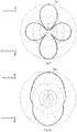
Figure 9 illustrates an emission pattern in which the antennas are disposed on both sides of the two-wheeledmotor vehicle 1 and no metal structure is present between the antennas. InFigure 9 , the electromagnetic waves in the same phase are emitted from the two antennas. In such an emission pattern Ep3, at a forward/rearward receiving point at which the distances from the two antennas are substantially equal to each other, the electromagnetic waves from the antennas are combined at the same phase, and thus are highlighted. However, the distances from the two antennas differ largely as the receiving point is shifted obliquely. When the distances from the antennas are each an odd multiple of a 1/2 wavelength, the electromagnetic waves are combined in the antiphase. This causes degraded electromagnetic waves. As a result, a position may be generated in the oblique direction in which the electromagnetic wave has a low intensity due to the distance and an angle relative to the antennas. - The electromagnetic waves in the traverse direction are combined by the phase difference determined from a distance between the two antennas. In
Figure 9 , the two antennas are disposed at a distance D having an interval of 1 wavelength. Accordingly, the electromagnetic waves are combined at the same phase and intensified mutually. On the other hand, in the oblique direction, a point may be generated depending on the position of the receiving point in which a difference in distance from the first antenna and the second antenna is an odd multiple of a 1/2 wavelength. At this point, the electromagnetic waves are degraded. As noted above, when the two antennas are disposed between which no metal structure is provided, satisfied communications are performable with the forward/rearward vehicles and the side vehicles. On the other hand, unstable communications are performed with the vehicles in the oblique direction. - In contrast to this, the arrangement of the antennas in
Embodiment 1 achieves the same antenna property as the ideal antenna property as illustrated inFigure 10 . In an emission pattern Ep4 according toEmbodiment 1, theantennas motor vehicle 1 can be transmitted and received. - In addition, the two
antennas - The following describes a two-wheeled motor vehicle of Embodiment 2 with reference to
Figures 11 and 12. Figures 11 and 12 each illustrate a configuration of antennas according to Embodiment 2. In Embodiment 2, the elements denoted by the same numerals as inEmbodiment 1 are common to the elements inEmbodiment 1, and thus the description thereof is to be omitted. In addition, the configurations of the two-wheeled motor vehicle and the antennas other than the following are common to the configurations inEmbodiment 1. - Embodiment 2 has the characteristic in that the antennas disposed in the two-wheeled
motor vehicle 1 each have directionality. InEmbodiment 1, the non-directional linear antennas are used. In contrast, in Embodiment 2, linear antennas having forward/rearward directionality are used, achieving a longer communication distance in the forward/rearward direction. - Antennas 20' and 21' in Embodiment 2 each include a ground plane 22' extending in the longitudinal direction of the vehicle. See
Figure 11 . That is, the ground plane 22' is oval having a long axis in the longitudinal direction of the vehicle. Instead of the oval ground plane 22', two metal wires 26' extending in the longitudinal direction of the vehicle may be used. SeeFigure 12 . - As noted above, a ground board (ground plane 22', metal wire 26') extending in the longitudinal direction of the vehicle is used, achieving reduction in length of the ground board in the vehicle width direction. Consequently, the antennas are readily disposed in a narrow space between the main frame 3 and the
vehicle body cover 14, leading to enhanced arrangement flexibility. - The following describes an antenna property in Embodiment 2.
Figure 13 illustrates the antenna property in Embodiment 2. A directionality antenna in Embodiment 2 achieves an antenna property similar to the ideal antenna property as illustrated inFigure 13 . An emission pattern Ep5 in Embodiment 2 can obtain an electromagnetic wave property having enhanced forward/rearward directionality although the electromagnetic wave has a lower intensity in the oblique direction than the emission pattern Ep4 inEmbodiment 1. Consequently, an oval emission pattern is obtainable having a long axis in the forward/rearward direction. As a result, the electromagnetic waves suitable for traveling of the two-wheeledmotor vehicle 1 can be transmitted and received. Also in Embodiment, since the two antenna 20' and 21' are disposed at the same level, a distance difference of the electromagnetic waves in the forward/rearward direction can be decreased. This allows sufficient communications. - The present invention is not limited to the above embodiments, but may be modified as follows:
-
- (1) In the
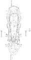
Embodiment 1, the twoantennas engine 11a. However, this is not limitative. Alternatively, theantennas engine 11a. Theantennas board 15, or may be disposed across the other metal accessories as illustrated inFigures 14 and15 . Examples of the accessories include abattery 16, afuel tank 30, anECU 31, and an ABS hydraulic unit (hydraulic pressure unit). That is, theantennas battery 16, across the ECU31, across the ABS hydraulic unit, or across thefuel tank 30.
Embodiment 1 adopts theengine unit 11 of a unit swing type in combination of theengine 11a and thetransmission case 11b. Alternatively, another type engine unit is adoptable. For instance, a rear wheel is suspended by a rear arm, and the engine is itself fixed on the vehicle body. Such an engine unit may be adopted. In this case, a transmission case may be used as the metal structure in addition to a cylinder, a crank case, and an oil pan that form the engine.
In any case, it is preferred that theantennas antennas antennas - (2) In the above embodiments, the antennas having the forward/rearward directionality or the non-directional antennas is adopted. However, this is not limitative. An antenna such as a cardioid antenna having hemispherical directionality may be adopted. In this case, a cardioid recess may be disposed inward the vehicle body.
- (3) In the above embodiments, the two-wheeled
motor vehicle 1 is a scooter type vehicle provided with an underbone-type frame. However, this is not limitative. For instance, other frames such as a backbone type frame and a diamond type frame may be adopted. In addition, the two-wheeledmotor vehicle 1 is not limited to the scooter type. Alternatively, a two-wheeled motor vehicle of other types such as a naked or a touring type may be adopted. -
- 1 ... two-wheeled motor vehicle
- 2 ... vehicle body frame
- 3 ... main frame
- 4 ... seat frame
- 5 ... head tube
- 7 ... front frame
- 11a ... engine
- 14 ... vehicle body cover
- 15 ... reinforcing board
- 16 ... battery
- 20, 20', 21, 21' ··· antenna
- 30 ... fuel tank
- 31 ... ECU
Claims (12)
- A two-wheeled motor vehicle, comprising:a vehicle body frame (2) with a main frame (3) and a seat frame (4) disposed at a rearward position of the main frame (3); anda first antenna (20, 20'),characterized in thata metal structure (11, 15, 16, 30, 31) is mounted on the main frame (3),the first antenna (20, 20') is disposed outside the main frame (3) in a vehicle width direction,the two-wheeled motor vehicle, comprises a second antenna (21,21') outside the main frame (3) and opposite to the first antenna (20, 20') with at least the metal structure (11, 15, 16, 30, 31) arranged between the first antenna (20, 20') and the second antenna (21,21'), andthe two-wheeled motor vehicle is configured to perform road-to-vehicle communications with roadside units and vehicle-to-vehicle communications with other vehicles using the first antenna (20, 20') and the second antenna (21, 21').
- The two-wheeled motor vehicle according to claim 1, wherein
the first antenna (20, 20') and the second antenna (21, 21') are each a linear antenna. - The two-wheeled motor vehicle according to claim 1 or 2, wherein
the first antenna (20') and the second antenna (21') each have forward/rearward directionality. - The two-wheeled motor vehicle according to claim 3, wherein
the linear antenna (20, 21) is a Brown antenna having a ground (22) longer in a longitudinal direction than in a vehicle width direction, and a linear unit (23) as a radiation conductor, and
the ground (22) has a length in the longitudinal direction that is longer than a length of the linear unit (23). - The two-wheeled motor vehicle according to any one of claims 1 to 4, wherein
the main frame (3) includes a front frame (7) disposed at a forward position of a head tube (5). - The two-wheeled motor vehicle according to any one of claims 1 to 5, wherein
the metal structure is an engine unit (11). - The two-wheeled motor vehicle according to any one of claims 1 to 5, wherein
the main frame (3) includes a reinforcing board (15) reinforcing rigidity of the main frame (3), and
the metal structure is the reinforcing board (15). - The two-wheeled motor vehicle according to any one of claims 1 to 5, wherein the metal structure is a metal accessory (16, 30, 31).
- The two-wheeled motor vehicle according to any one of claims 1 to 8, wherein
the first antenna (20, 20') and the second antenna (21, 21') are arranged at the two-wheeled motor vehicle at a position that does not overlap with the rider's feet in a travelling attitude in side view. - The two-wheeled motor vehicle according to any one of claims 1 to 9, wherein
the first antenna (20, 20') and the second antenna (21,21') are disposed between a cover (14) and the main frame (3), the cover (14) covering at least a part of the main frame (3). - The two-wheeled motor vehicle according to any one of claims 1 to 10, wherein
the first antenna (20, 20') and the second antenna (21, 21') are disposed at the same level in side view. - The two-wheeled motor vehicle according to any one of claims 1 to 11, wherein
the first antenna (20, 20') and the second antenna (21, 21') overlap the main frame (3) or an engine (11) in side view.
Applications Claiming Priority (2)
| Application Number | Priority Date | Filing Date | Title |
|---|---|---|---|
| JP2013068991 | 2013-03-28 | ||
| PCT/JP2014/057908 WO2014157011A1 (en) | 2013-03-28 | 2014-03-20 | Motorcycle |
Publications (3)
| Publication Number | Publication Date |
|---|---|
| EP2980920A1 EP2980920A1 (en) | 2016-02-03 |
| EP2980920A4 EP2980920A4 (en) | 2016-03-23 |
| EP2980920B1 true EP2980920B1 (en) | 2017-06-28 |
Family
ID=51623988
Family Applications (1)
| Application Number | Title | Priority Date | Filing Date |
|---|---|---|---|
| EP14775908.8A Active EP2980920B1 (en) | 2013-03-28 | 2014-03-20 | Motorcycle |
Country Status (4)
| Country | Link |
|---|---|
| US (1) | US10249942B2 (en) |
| EP (1) | EP2980920B1 (en) |
| JP (1) | JP6028090B2 (en) |
| WO (1) | WO2014157011A1 (en) |
Families Citing this family (4)
| Publication number | Priority date | Publication date | Assignee | Title |
|---|---|---|---|---|
| JP6488624B2 (en) * | 2014-10-06 | 2019-03-27 | スズキ株式会社 | Motorcycle / Tricycle |
| TW201902024A (en) * | 2017-05-26 | 2019-01-01 | 銳鋒股份有限公司 | Vehicle computing device |
| JP7066839B2 (en) * | 2018-05-23 | 2022-05-13 | 本田技研工業株式会社 | Saddle-type vehicle |
| WO2020045252A1 (en) * | 2018-08-27 | 2020-03-05 | ヤマハ発動機株式会社 | V2x communication antenna-mounted leaning vehicle |
Family Cites Families (17)
| Publication number | Priority date | Publication date | Assignee | Title |
|---|---|---|---|---|
| US2267266A (en) * | 1936-06-15 | 1941-12-23 | Edward C Baxley | Antenna system |
| US4658266A (en) | 1983-10-13 | 1987-04-14 | Doty Archibald C Jun | Vertical antenna with improved artificial ground system |
| JPH0591003A (en) | 1991-09-25 | 1993-04-09 | Mazda Motor Corp | On-vehicle antenna system |
| JPH05238438A (en) * | 1992-02-28 | 1993-09-17 | Shizuo Kawai | Improvement of fuel consumption of vehicle such as automobile and motorcycle |
| JP4156783B2 (en) | 2000-04-03 | 2008-09-24 | 本田技研工業株式会社 | Motorcycle antenna arrangement structure |
| EP1353403B1 (en) * | 2002-04-12 | 2007-01-03 | Honda Giken Kogyo Kabushiki Kaisha | Vehicle intercommunication apparatus |
| JP2003309419A (en) | 2002-04-16 | 2003-10-31 | Nippon Dengyo Kosaku Co Ltd | Ground plane antenna |
| JP3793129B2 (en) * | 2002-08-30 | 2006-07-05 | 川崎重工業株式会社 | Motorcycle body frame |
| JP4005883B2 (en) * | 2002-09-13 | 2007-11-14 | ヤマハ発動機株式会社 | Rear arm of motorcycle |
| US7230545B2 (en) * | 2003-11-07 | 2007-06-12 | Nattel Group, Inc. | Automobile communication and registry system |
| JP2005234921A (en) | 2004-02-20 | 2005-09-02 | Honda Motor Co Ltd | Inter-vehicle communication device |
| JP2006199168A (en) * | 2005-01-21 | 2006-08-03 | Kawasaki Heavy Ind Ltd | Antitheft device for recreational vehicle |
| JP2008114654A (en) | 2006-11-01 | 2008-05-22 | Yamaha Motor Co Ltd | Motorcycle |
| JP5158964B2 (en) | 2008-09-30 | 2013-03-06 | 本田技研工業株式会社 | Motorcycle navigation device |
| JP2010120626A (en) * | 2008-10-24 | 2010-06-03 | Yamaha Motor Co Ltd | Motorcycle |
| JP2010120627A (en) * | 2008-10-24 | 2010-06-03 | Yamaha Motor Co Ltd | Motorcycle |
| JP5427735B2 (en) * | 2010-08-31 | 2014-02-26 | 本田技研工業株式会社 | Saddle riding |
-
2014
- 2014-03-20 EP EP14775908.8A patent/EP2980920B1/en active Active
- 2014-03-20 JP JP2015508441A patent/JP6028090B2/en active Active
- 2014-03-20 WO PCT/JP2014/057908 patent/WO2014157011A1/en active Application Filing
- 2014-03-20 US US14/780,816 patent/US10249942B2/en active Active
Also Published As
| Publication number | Publication date |
|---|---|
| JP6028090B2 (en) | 2016-11-16 |
| US10249942B2 (en) | 2019-04-02 |
| WO2014157011A1 (en) | 2014-10-02 |
| EP2980920A1 (en) | 2016-02-03 |
| US20160043462A1 (en) | 2016-02-11 |
| JPWO2014157011A1 (en) | 2017-02-16 |
| EP2980920A4 (en) | 2016-03-23 |
Similar Documents
| Publication | Publication Date | Title |
|---|---|---|
| US9893415B2 (en) | Two-wheeled motor vehicle | |
| EP2980920B1 (en) | Motorcycle | |
| US11588229B2 (en) | Straddle type vehicle | |
| US11909106B2 (en) | V2X communication antenna-mounted leaning vehicle | |
| EP2180332B1 (en) | Motorcycle | |
| CN112188980B (en) | Saddle-ride type vehicle | |
| JP4080497B2 (en) | Antenna device | |
| JP2004179790A (en) | On-vehicle antenna system | |
| US20170179583A1 (en) | Straddled vehicle | |
| KR101698030B1 (en) | Antenna | |
| JP2002135025A (en) | On-vehicle antenna device | |
| JP4525390B2 (en) | Warning target detection device and warning target detection system | |
| JP7191963B2 (en) | Lean vehicle equipped with an antenna for inter-vehicle communication, and an antenna for inter-vehicle communication configured to be mounted on the lean vehicle | |
| JP7183279B2 (en) | Lean vehicle equipped with an antenna for inter-vehicle communication, and an antenna for inter-vehicle communication configured to be mounted on the lean vehicle | |
| JP2007064730A (en) | On-vehicle radar system | |
| JPWO2020045391A1 (en) | Vehicle-to-vehicle communication antenna mounted Lean vehicle and vehicle-to-vehicle communication antenna configured to be mounted on the lean vehicle | |
| JP2008126805A (en) | Tire state detecting device |
Legal Events
| Date | Code | Title | Description |
|---|---|---|---|
| PUAI | Public reference made under article 153(3) epc to a published international application that has entered the european phase |
Free format text: ORIGINAL CODE: 0009012 |
|
| 17P | Request for examination filed |
Effective date: 20151028 |
|
| AK | Designated contracting states |
Kind code of ref document: A1 Designated state(s): AL AT BE BG CH CY CZ DE DK EE ES FI FR GB GR HR HU IE IS IT LI LT LU LV MC MK MT NL NO PL PT RO RS SE SI SK SM TR |
|
| AX | Request for extension of the european patent |
Extension state: BA ME |
|
| A4 | Supplementary search report drawn up and despatched |
Effective date: 20160222 |
|
| RIC1 | Information provided on ipc code assigned before grant |
Ipc: H01Q 1/32 20060101AFI20160216BHEP Ipc: B62J 99/00 20090101ALI20160216BHEP Ipc: H01Q 21/29 20060101ALI20160216BHEP Ipc: H01Q 21/28 20060101ALI20160216BHEP Ipc: B62K 19/40 20060101ALI20160216BHEP Ipc: H01Q 9/38 20060101ALI20160216BHEP Ipc: B62K 11/04 20060101ALI20160216BHEP Ipc: H01Q 1/22 20060101ALI20160216BHEP Ipc: H01Q 21/08 20060101ALI20160216BHEP Ipc: H01Q 1/48 20060101ALI20160216BHEP |
|
| DAX | Request for extension of the european patent (deleted) | ||
| GRAP | Despatch of communication of intention to grant a patent |
Free format text: ORIGINAL CODE: EPIDOSNIGR1 |
|
| RIC1 | Information provided on ipc code assigned before grant |
Ipc: H01Q 9/38 20060101ALI20161220BHEP Ipc: H01Q 1/32 20060101AFI20161220BHEP Ipc: H01Q 1/48 20060101ALI20161220BHEP Ipc: B62K 11/04 20060101ALI20161220BHEP Ipc: H01Q 21/08 20060101ALI20161220BHEP Ipc: B62J 99/00 20090101ALI20161220BHEP Ipc: H01Q 1/22 20060101ALI20161220BHEP Ipc: H01Q 21/28 20060101ALI20161220BHEP Ipc: B62K 19/40 20060101ALI20161220BHEP Ipc: H01Q 21/29 20060101ALI20161220BHEP |
|
| INTG | Intention to grant announced |
Effective date: 20170113 |
|
| GRAS | Grant fee paid |
Free format text: ORIGINAL CODE: EPIDOSNIGR3 |
|
| GRAA | (expected) grant |
Free format text: ORIGINAL CODE: 0009210 |
|
| AK | Designated contracting states |
Kind code of ref document: B1 Designated state(s): AL AT BE BG CH CY CZ DE DK EE ES FI FR GB GR HR HU IE IS IT LI LT LU LV MC MK MT NL NO PL PT RO RS SE SI SK SM TR |
|
| REG | Reference to a national code |
Ref country code: GB Ref legal event code: FG4D |
|
| REG | Reference to a national code |
Ref country code: CH Ref legal event code: EP |
|
| REG | Reference to a national code |
Ref country code: AT Ref legal event code: REF Ref document number: 905596 Country of ref document: AT Kind code of ref document: T Effective date: 20170715 |
|
| REG | Reference to a national code |
Ref country code: IE Ref legal event code: FG4D |
|
| REG | Reference to a national code |
Ref country code: DE Ref legal event code: R096 Ref document number: 602014011324 Country of ref document: DE |
|
| PG25 | Lapsed in a contracting state [announced via postgrant information from national office to epo] |
Ref country code: FI Free format text: LAPSE BECAUSE OF FAILURE TO SUBMIT A TRANSLATION OF THE DESCRIPTION OR TO PAY THE FEE WITHIN THE PRESCRIBED TIME-LIMIT Effective date: 20170628 Ref country code: LT Free format text: LAPSE BECAUSE OF FAILURE TO SUBMIT A TRANSLATION OF THE DESCRIPTION OR TO PAY THE FEE WITHIN THE PRESCRIBED TIME-LIMIT Effective date: 20170628 Ref country code: NO Free format text: LAPSE BECAUSE OF FAILURE TO SUBMIT A TRANSLATION OF THE DESCRIPTION OR TO PAY THE FEE WITHIN THE PRESCRIBED TIME-LIMIT Effective date: 20170928 Ref country code: HR Free format text: LAPSE BECAUSE OF FAILURE TO SUBMIT A TRANSLATION OF THE DESCRIPTION OR TO PAY THE FEE WITHIN THE PRESCRIBED TIME-LIMIT Effective date: 20170628 Ref country code: GR Free format text: LAPSE BECAUSE OF FAILURE TO SUBMIT A TRANSLATION OF THE DESCRIPTION OR TO PAY THE FEE WITHIN THE PRESCRIBED TIME-LIMIT Effective date: 20170929 |
|
| REG | Reference to a national code |
Ref country code: NL Ref legal event code: MP Effective date: 20170628 |
|
| REG | Reference to a national code |
Ref country code: LT Ref legal event code: MG4D |
|
| REG | Reference to a national code |
Ref country code: AT Ref legal event code: MK05 Ref document number: 905596 Country of ref document: AT Kind code of ref document: T Effective date: 20170628 |
|
| PG25 | Lapsed in a contracting state [announced via postgrant information from national office to epo] |
Ref country code: BG Free format text: LAPSE BECAUSE OF FAILURE TO SUBMIT A TRANSLATION OF THE DESCRIPTION OR TO PAY THE FEE WITHIN THE PRESCRIBED TIME-LIMIT Effective date: 20170928 Ref country code: SE Free format text: LAPSE BECAUSE OF FAILURE TO SUBMIT A TRANSLATION OF THE DESCRIPTION OR TO PAY THE FEE WITHIN THE PRESCRIBED TIME-LIMIT Effective date: 20170628 Ref country code: RS Free format text: LAPSE BECAUSE OF FAILURE TO SUBMIT A TRANSLATION OF THE DESCRIPTION OR TO PAY THE FEE WITHIN THE PRESCRIBED TIME-LIMIT Effective date: 20170628 Ref country code: NL Free format text: LAPSE BECAUSE OF FAILURE TO SUBMIT A TRANSLATION OF THE DESCRIPTION OR TO PAY THE FEE WITHIN THE PRESCRIBED TIME-LIMIT Effective date: 20170628 Ref country code: LV Free format text: LAPSE BECAUSE OF FAILURE TO SUBMIT A TRANSLATION OF THE DESCRIPTION OR TO PAY THE FEE WITHIN THE PRESCRIBED TIME-LIMIT Effective date: 20170628 |
|
| PG25 | Lapsed in a contracting state [announced via postgrant information from national office to epo] |
Ref country code: AT Free format text: LAPSE BECAUSE OF FAILURE TO SUBMIT A TRANSLATION OF THE DESCRIPTION OR TO PAY THE FEE WITHIN THE PRESCRIBED TIME-LIMIT Effective date: 20170628 Ref country code: EE Free format text: LAPSE BECAUSE OF FAILURE TO SUBMIT A TRANSLATION OF THE DESCRIPTION OR TO PAY THE FEE WITHIN THE PRESCRIBED TIME-LIMIT Effective date: 20170628 Ref country code: SK Free format text: LAPSE BECAUSE OF FAILURE TO SUBMIT A TRANSLATION OF THE DESCRIPTION OR TO PAY THE FEE WITHIN THE PRESCRIBED TIME-LIMIT Effective date: 20170628 Ref country code: RO Free format text: LAPSE BECAUSE OF FAILURE TO SUBMIT A TRANSLATION OF THE DESCRIPTION OR TO PAY THE FEE WITHIN THE PRESCRIBED TIME-LIMIT Effective date: 20170628 Ref country code: CZ Free format text: LAPSE BECAUSE OF FAILURE TO SUBMIT A TRANSLATION OF THE DESCRIPTION OR TO PAY THE FEE WITHIN THE PRESCRIBED TIME-LIMIT Effective date: 20170628 |
|
| PG25 | Lapsed in a contracting state [announced via postgrant information from national office to epo] |
Ref country code: IS Free format text: LAPSE BECAUSE OF FAILURE TO SUBMIT A TRANSLATION OF THE DESCRIPTION OR TO PAY THE FEE WITHIN THE PRESCRIBED TIME-LIMIT Effective date: 20171028 Ref country code: SM Free format text: LAPSE BECAUSE OF FAILURE TO SUBMIT A TRANSLATION OF THE DESCRIPTION OR TO PAY THE FEE WITHIN THE PRESCRIBED TIME-LIMIT Effective date: 20170628 Ref country code: PL Free format text: LAPSE BECAUSE OF FAILURE TO SUBMIT A TRANSLATION OF THE DESCRIPTION OR TO PAY THE FEE WITHIN THE PRESCRIBED TIME-LIMIT Effective date: 20170628 Ref country code: ES Free format text: LAPSE BECAUSE OF FAILURE TO SUBMIT A TRANSLATION OF THE DESCRIPTION OR TO PAY THE FEE WITHIN THE PRESCRIBED TIME-LIMIT Effective date: 20170628 |
|
| REG | Reference to a national code |
Ref country code: FR Ref legal event code: PLFP Year of fee payment: 5 |
|
| REG | Reference to a national code |
Ref country code: DE Ref legal event code: R097 Ref document number: 602014011324 Country of ref document: DE |
|
| PG25 | Lapsed in a contracting state [announced via postgrant information from national office to epo] |
Ref country code: DK Free format text: LAPSE BECAUSE OF FAILURE TO SUBMIT A TRANSLATION OF THE DESCRIPTION OR TO PAY THE FEE WITHIN THE PRESCRIBED TIME-LIMIT Effective date: 20170628 |
|
| PLBE | No opposition filed within time limit |
Free format text: ORIGINAL CODE: 0009261 |
|
| STAA | Information on the status of an ep patent application or granted ep patent |
Free format text: STATUS: NO OPPOSITION FILED WITHIN TIME LIMIT |
|
| 26N | No opposition filed |
Effective date: 20180329 |
|
| PG25 | Lapsed in a contracting state [announced via postgrant information from national office to epo] |
Ref country code: SI Free format text: LAPSE BECAUSE OF FAILURE TO SUBMIT A TRANSLATION OF THE DESCRIPTION OR TO PAY THE FEE WITHIN THE PRESCRIBED TIME-LIMIT Effective date: 20170628 |
|
| REG | Reference to a national code |
Ref country code: CH Ref legal event code: PL |
|
| PG25 | Lapsed in a contracting state [announced via postgrant information from national office to epo] |
Ref country code: MC Free format text: LAPSE BECAUSE OF FAILURE TO SUBMIT A TRANSLATION OF THE DESCRIPTION OR TO PAY THE FEE WITHIN THE PRESCRIBED TIME-LIMIT Effective date: 20170628 |
|
| REG | Reference to a national code |
Ref country code: BE Ref legal event code: MM Effective date: 20180331 |
|
| REG | Reference to a national code |
Ref country code: IE Ref legal event code: MM4A |
|
| PG25 | Lapsed in a contracting state [announced via postgrant information from national office to epo] |
Ref country code: LU Free format text: LAPSE BECAUSE OF NON-PAYMENT OF DUE FEES Effective date: 20180320 |
|
| PG25 | Lapsed in a contracting state [announced via postgrant information from national office to epo] |
Ref country code: IE Free format text: LAPSE BECAUSE OF NON-PAYMENT OF DUE FEES Effective date: 20180320 |
|
| PG25 | Lapsed in a contracting state [announced via postgrant information from national office to epo] |
Ref country code: LI Free format text: LAPSE BECAUSE OF NON-PAYMENT OF DUE FEES Effective date: 20180331 Ref country code: CH Free format text: LAPSE BECAUSE OF NON-PAYMENT OF DUE FEES Effective date: 20180331 Ref country code: BE Free format text: LAPSE BECAUSE OF NON-PAYMENT OF DUE FEES Effective date: 20180331 |
|
| PG25 | Lapsed in a contracting state [announced via postgrant information from national office to epo] |
Ref country code: MT Free format text: LAPSE BECAUSE OF NON-PAYMENT OF DUE FEES Effective date: 20180320 |
|
| PG25 | Lapsed in a contracting state [announced via postgrant information from national office to epo] |
Ref country code: TR Free format text: LAPSE BECAUSE OF FAILURE TO SUBMIT A TRANSLATION OF THE DESCRIPTION OR TO PAY THE FEE WITHIN THE PRESCRIBED TIME-LIMIT Effective date: 20170628 |
|
| PG25 | Lapsed in a contracting state [announced via postgrant information from national office to epo] |
Ref country code: PT Free format text: LAPSE BECAUSE OF FAILURE TO SUBMIT A TRANSLATION OF THE DESCRIPTION OR TO PAY THE FEE WITHIN THE PRESCRIBED TIME-LIMIT Effective date: 20170628 |
|
| PG25 | Lapsed in a contracting state [announced via postgrant information from national office to epo] |
Ref country code: CY Free format text: LAPSE BECAUSE OF FAILURE TO SUBMIT A TRANSLATION OF THE DESCRIPTION OR TO PAY THE FEE WITHIN THE PRESCRIBED TIME-LIMIT Effective date: 20170628 Ref country code: HU Free format text: LAPSE BECAUSE OF FAILURE TO SUBMIT A TRANSLATION OF THE DESCRIPTION OR TO PAY THE FEE WITHIN THE PRESCRIBED TIME-LIMIT; INVALID AB INITIO Effective date: 20140320 Ref country code: MK Free format text: LAPSE BECAUSE OF NON-PAYMENT OF DUE FEES Effective date: 20170628 |
|
| PG25 | Lapsed in a contracting state [announced via postgrant information from national office to epo] |
Ref country code: AL Free format text: LAPSE BECAUSE OF FAILURE TO SUBMIT A TRANSLATION OF THE DESCRIPTION OR TO PAY THE FEE WITHIN THE PRESCRIBED TIME-LIMIT Effective date: 20170628 |
|
| PGFP | Annual fee paid to national office [announced via postgrant information from national office to epo] |
Ref country code: FR Payment date: 20230324 Year of fee payment: 10 |
|
| PGFP | Annual fee paid to national office [announced via postgrant information from national office to epo] |
Ref country code: GB Payment date: 20230322 Year of fee payment: 10 Ref country code: DE Payment date: 20230321 Year of fee payment: 10 |
|
| P01 | Opt-out of the competence of the unified patent court (upc) registered |
Effective date: 20230527 |
|
| PGFP | Annual fee paid to national office [announced via postgrant information from national office to epo] |
Ref country code: IT Payment date: 20230328 Year of fee payment: 10 |