WO2014156930A1 - 回路部材の接続方法、及び接合体 - Google Patents
回路部材の接続方法、及び接合体 Download PDFInfo
- Publication number
- WO2014156930A1 WO2014156930A1 PCT/JP2014/057696 JP2014057696W WO2014156930A1 WO 2014156930 A1 WO2014156930 A1 WO 2014156930A1 JP 2014057696 W JP2014057696 W JP 2014057696W WO 2014156930 A1 WO2014156930 A1 WO 2014156930A1
- Authority
- WO
- WIPO (PCT)
- Prior art keywords
- circuit member
- anisotropic conductive
- conductive film
- solder particles
- terminal
- Prior art date
Links
Images

Classifications
-
- C—CHEMISTRY; METALLURGY
- C09—DYES; PAINTS; POLISHES; NATURAL RESINS; ADHESIVES; COMPOSITIONS NOT OTHERWISE PROVIDED FOR; APPLICATIONS OF MATERIALS NOT OTHERWISE PROVIDED FOR
- C09J—ADHESIVES; NON-MECHANICAL ASPECTS OF ADHESIVE PROCESSES IN GENERAL; ADHESIVE PROCESSES NOT PROVIDED FOR ELSEWHERE; USE OF MATERIALS AS ADHESIVES
- C09J4/00—Adhesives based on organic non-macromolecular compounds having at least one polymerisable carbon-to-carbon unsaturated bond ; adhesives, based on monomers of macromolecular compounds of groups C09J183/00 - C09J183/16
-
- H—ELECTRICITY
- H01—ELECTRIC ELEMENTS
- H01L—SEMICONDUCTOR DEVICES NOT COVERED BY CLASS H10
- H01L24/00—Arrangements for connecting or disconnecting semiconductor or solid-state bodies; Methods or apparatus related thereto
- H01L24/01—Means for bonding being attached to, or being formed on, the surface to be connected, e.g. chip-to-package, die-attach, "first-level" interconnects; Manufacturing methods related thereto
- H01L24/26—Layer connectors, e.g. plate connectors, solder or adhesive layers; Manufacturing methods related thereto
- H01L24/28—Structure, shape, material or disposition of the layer connectors prior to the connecting process
- H01L24/29—Structure, shape, material or disposition of the layer connectors prior to the connecting process of an individual layer connector
-
- H—ELECTRICITY
- H01—ELECTRIC ELEMENTS
- H01L—SEMICONDUCTOR DEVICES NOT COVERED BY CLASS H10
- H01L24/00—Arrangements for connecting or disconnecting semiconductor or solid-state bodies; Methods or apparatus related thereto
- H01L24/80—Methods for connecting semiconductor or other solid state bodies using means for bonding being attached to, or being formed on, the surface to be connected
- H01L24/83—Methods for connecting semiconductor or other solid state bodies using means for bonding being attached to, or being formed on, the surface to be connected using a layer connector
-
- H—ELECTRICITY
- H05—ELECTRIC TECHNIQUES NOT OTHERWISE PROVIDED FOR
- H05K—PRINTED CIRCUITS; CASINGS OR CONSTRUCTIONAL DETAILS OF ELECTRIC APPARATUS; MANUFACTURE OF ASSEMBLAGES OF ELECTRICAL COMPONENTS
- H05K3/00—Apparatus or processes for manufacturing printed circuits
- H05K3/30—Assembling printed circuits with electric components, e.g. with resistor
- H05K3/32—Assembling printed circuits with electric components, e.g. with resistor electrically connecting electric components or wires to printed circuits
- H05K3/321—Assembling printed circuits with electric components, e.g. with resistor electrically connecting electric components or wires to printed circuits by conductive adhesives
- H05K3/323—Assembling printed circuits with electric components, e.g. with resistor electrically connecting electric components or wires to printed circuits by conductive adhesives by applying an anisotropic conductive adhesive layer over an array of pads
-
- H—ELECTRICITY
- H01—ELECTRIC ELEMENTS
- H01L—SEMICONDUCTOR DEVICES NOT COVERED BY CLASS H10
- H01L2224/00—Indexing scheme for arrangements for connecting or disconnecting semiconductor or solid-state bodies and methods related thereto as covered by H01L24/00
- H01L2224/01—Means for bonding being attached to, or being formed on, the surface to be connected, e.g. chip-to-package, die-attach, "first-level" interconnects; Manufacturing methods related thereto
- H01L2224/26—Layer connectors, e.g. plate connectors, solder or adhesive layers; Manufacturing methods related thereto
- H01L2224/28—Structure, shape, material or disposition of the layer connectors prior to the connecting process
- H01L2224/29—Structure, shape, material or disposition of the layer connectors prior to the connecting process of an individual layer connector
- H01L2224/29001—Core members of the layer connector
- H01L2224/29099—Material
- H01L2224/29198—Material with a principal constituent of the material being a combination of two or more materials in the form of a matrix with a filler, i.e. being a hybrid material, e.g. segmented structures, foams
- H01L2224/29199—Material of the matrix
- H01L2224/2929—Material of the matrix with a principal constituent of the material being a polymer, e.g. polyester, phenolic based polymer, epoxy
-
- H—ELECTRICITY
- H01—ELECTRIC ELEMENTS
- H01L—SEMICONDUCTOR DEVICES NOT COVERED BY CLASS H10
- H01L2224/00—Indexing scheme for arrangements for connecting or disconnecting semiconductor or solid-state bodies and methods related thereto as covered by H01L24/00
- H01L2224/01—Means for bonding being attached to, or being formed on, the surface to be connected, e.g. chip-to-package, die-attach, "first-level" interconnects; Manufacturing methods related thereto
- H01L2224/26—Layer connectors, e.g. plate connectors, solder or adhesive layers; Manufacturing methods related thereto
- H01L2224/28—Structure, shape, material or disposition of the layer connectors prior to the connecting process
- H01L2224/29—Structure, shape, material or disposition of the layer connectors prior to the connecting process of an individual layer connector
- H01L2224/29001—Core members of the layer connector
- H01L2224/29099—Material
- H01L2224/29198—Material with a principal constituent of the material being a combination of two or more materials in the form of a matrix with a filler, i.e. being a hybrid material, e.g. segmented structures, foams
- H01L2224/29298—Fillers
- H01L2224/29299—Base material
- H01L2224/293—Base material with a principal constituent of the material being a metal or a metalloid, e.g. boron [B], silicon [Si], germanium [Ge], arsenic [As], antimony [Sb], tellurium [Te] and polonium [Po], and alloys thereof
- H01L2224/29301—Base material with a principal constituent of the material being a metal or a metalloid, e.g. boron [B], silicon [Si], germanium [Ge], arsenic [As], antimony [Sb], tellurium [Te] and polonium [Po], and alloys thereof the principal constituent melting at a temperature of less than 400°C
- H01L2224/29311—Tin [Sn] as principal constituent
-
- H—ELECTRICITY
- H01—ELECTRIC ELEMENTS
- H01L—SEMICONDUCTOR DEVICES NOT COVERED BY CLASS H10
- H01L2224/00—Indexing scheme for arrangements for connecting or disconnecting semiconductor or solid-state bodies and methods related thereto as covered by H01L24/00
- H01L2224/01—Means for bonding being attached to, or being formed on, the surface to be connected, e.g. chip-to-package, die-attach, "first-level" interconnects; Manufacturing methods related thereto
- H01L2224/26—Layer connectors, e.g. plate connectors, solder or adhesive layers; Manufacturing methods related thereto
- H01L2224/28—Structure, shape, material or disposition of the layer connectors prior to the connecting process
- H01L2224/29—Structure, shape, material or disposition of the layer connectors prior to the connecting process of an individual layer connector
- H01L2224/29001—Core members of the layer connector
- H01L2224/29099—Material
- H01L2224/29198—Material with a principal constituent of the material being a combination of two or more materials in the form of a matrix with a filler, i.e. being a hybrid material, e.g. segmented structures, foams
- H01L2224/29298—Fillers
- H01L2224/29299—Base material
- H01L2224/293—Base material with a principal constituent of the material being a metal or a metalloid, e.g. boron [B], silicon [Si], germanium [Ge], arsenic [As], antimony [Sb], tellurium [Te] and polonium [Po], and alloys thereof
- H01L2224/29301—Base material with a principal constituent of the material being a metal or a metalloid, e.g. boron [B], silicon [Si], germanium [Ge], arsenic [As], antimony [Sb], tellurium [Te] and polonium [Po], and alloys thereof the principal constituent melting at a temperature of less than 400°C
- H01L2224/29316—Lead [Pb] as principal constituent
-
- H—ELECTRICITY
- H01—ELECTRIC ELEMENTS
- H01L—SEMICONDUCTOR DEVICES NOT COVERED BY CLASS H10
- H01L2224/00—Indexing scheme for arrangements for connecting or disconnecting semiconductor or solid-state bodies and methods related thereto as covered by H01L24/00
- H01L2224/80—Methods for connecting semiconductor or other solid state bodies using means for bonding being attached to, or being formed on, the surface to be connected
- H01L2224/83—Methods for connecting semiconductor or other solid state bodies using means for bonding being attached to, or being formed on, the surface to be connected using a layer connector
- H01L2224/83009—Pre-treatment of the layer connector or the bonding area
- H01L2224/83022—Cleaning the bonding area, e.g. oxide removal step, desmearing
-
- H—ELECTRICITY
- H01—ELECTRIC ELEMENTS
- H01L—SEMICONDUCTOR DEVICES NOT COVERED BY CLASS H10
- H01L2224/00—Indexing scheme for arrangements for connecting or disconnecting semiconductor or solid-state bodies and methods related thereto as covered by H01L24/00
- H01L2224/80—Methods for connecting semiconductor or other solid state bodies using means for bonding being attached to, or being formed on, the surface to be connected
- H01L2224/83—Methods for connecting semiconductor or other solid state bodies using means for bonding being attached to, or being formed on, the surface to be connected using a layer connector
- H01L2224/832—Applying energy for connecting
- H01L2224/83201—Compression bonding
- H01L2224/83205—Ultrasonic bonding
-
- H—ELECTRICITY
- H01—ELECTRIC ELEMENTS
- H01L—SEMICONDUCTOR DEVICES NOT COVERED BY CLASS H10
- H01L2224/00—Indexing scheme for arrangements for connecting or disconnecting semiconductor or solid-state bodies and methods related thereto as covered by H01L24/00
- H01L2224/80—Methods for connecting semiconductor or other solid state bodies using means for bonding being attached to, or being formed on, the surface to be connected
- H01L2224/83—Methods for connecting semiconductor or other solid state bodies using means for bonding being attached to, or being formed on, the surface to be connected using a layer connector
- H01L2224/838—Bonding techniques
- H01L2224/8385—Bonding techniques using a polymer adhesive, e.g. an adhesive based on silicone, epoxy, polyimide, polyester
- H01L2224/83851—Bonding techniques using a polymer adhesive, e.g. an adhesive based on silicone, epoxy, polyimide, polyester being an anisotropic conductive adhesive
-
- H—ELECTRICITY
- H01—ELECTRIC ELEMENTS
- H01L—SEMICONDUCTOR DEVICES NOT COVERED BY CLASS H10
- H01L2924/00—Indexing scheme for arrangements or methods for connecting or disconnecting semiconductor or solid-state bodies as covered by H01L24/00
- H01L2924/15—Details of package parts other than the semiconductor or other solid state devices to be connected
- H01L2924/151—Die mounting substrate
- H01L2924/156—Material
- H01L2924/15786—Material with a principal constituent of the material being a non metallic, non metalloid inorganic material
- H01L2924/15788—Glasses, e.g. amorphous oxides, nitrides or fluorides
-
- H—ELECTRICITY
- H05—ELECTRIC TECHNIQUES NOT OTHERWISE PROVIDED FOR
- H05K—PRINTED CIRCUITS; CASINGS OR CONSTRUCTIONAL DETAILS OF ELECTRIC APPARATUS; MANUFACTURE OF ASSEMBLAGES OF ELECTRICAL COMPONENTS
- H05K1/00—Printed circuits
- H05K1/18—Printed circuits structurally associated with non-printed electric components
- H05K1/189—Printed circuits structurally associated with non-printed electric components characterised by the use of a flexible or folded printed circuit
-
- H—ELECTRICITY
- H05—ELECTRIC TECHNIQUES NOT OTHERWISE PROVIDED FOR
- H05K—PRINTED CIRCUITS; CASINGS OR CONSTRUCTIONAL DETAILS OF ELECTRIC APPARATUS; MANUFACTURE OF ASSEMBLAGES OF ELECTRICAL COMPONENTS
- H05K2203/00—Indexing scheme relating to apparatus or processes for manufacturing printed circuits covered by H05K3/00
- H05K2203/02—Details related to mechanical or acoustic processing, e.g. drilling, punching, cutting, using ultrasound
- H05K2203/0285—Using ultrasound, e.g. for cleaning, soldering or wet treatment
-
- H—ELECTRICITY
- H05—ELECTRIC TECHNIQUES NOT OTHERWISE PROVIDED FOR
- H05K—PRINTED CIRCUITS; CASINGS OR CONSTRUCTIONAL DETAILS OF ELECTRIC APPARATUS; MANUFACTURE OF ASSEMBLAGES OF ELECTRICAL COMPONENTS
- H05K3/00—Apparatus or processes for manufacturing printed circuits
- H05K3/36—Assembling printed circuits with other printed circuits
- H05K3/361—Assembling flexible printed circuits with other printed circuits
Definitions
- the present invention relates to a circuit member connection method and a joined body.
- a tape-shaped connection material for example, anisotropic conductive film (ACF)
- ACF anisotropic conductive film
- This anisotropic conductive film is used, for example, to connect a terminal of a flexible printed circuit (FPC) or IC (Integrated Circuit) chip and an electrode formed on a glass substrate of an LCD (Liquid Crystal Display) panel. In other words, it is used when various terminals are bonded and electrically connected.
- FPC flexible printed circuit
- IC Integrated Circuit
- preflux Organic Solderability Preservative
- OSP Organic Solderability Preservative
- the preflux for example, imidazole preflux is known.
- the circuit member that has been rust-proofed by the preflux is connected using the anisotropic conductive film, there is a problem that the preflux layer present on the terminal of the circuit member inhibits conduction. Therefore, there is a need for a solution to this problem.
- connection using the said anisotropic conductive film it is calculated
- a method for connecting electronic components has been proposed that includes a step of curing the adhesive using heat generated from the adhesive itself (see, for example, Patent Document 1).
- connection method of the circuit member that has excellent connection reliability and can be connected in a short time, and the circuit member At present, it is required to provide a joined body obtained by the above connection method.
- the present invention makes it a subject to solve the said various problems in the past and to achieve the following objectives. That is, the present invention provides a circuit member connection method that is excellent in connection reliability and can be connected in a short time when connecting a circuit member that has been rust-prevented with a rust inhibitor using an anisotropic conductive film, And it aims at providing the conjugate
- Means for solving the problems are as follows. That is, ⁇ 1> A circuit member connection method for connecting a terminal of a first circuit member and a terminal of a second circuit member, An arrangement step of arranging an anisotropic conductive film containing a radical polymerizable substance, an organic peroxide, and solder particles on the first circuit member, and the second circuit member in this order.
- the circuit member connection method is characterized in that at least one of the terminal of the first circuit member and the terminal of the second circuit member is subjected to a rust prevention treatment with a rust inhibitor.
- ⁇ 5> The circuit member connection method according to any one of ⁇ 1> to ⁇ 4>, wherein the ultrasonic waves vibrate perpendicularly to a plane of the second circuit member.
- ⁇ 6> A joined body obtained by the method for connecting circuit members according to any one of ⁇ 1> to ⁇ 5>.
- the conventional problems can be solved, the object can be achieved, and when connecting a circuit member that has been rust-prevented by a rust inhibitor using an anisotropic conductive film,
- the connection method of the circuit member which is excellent in connection reliability and can be connected in a short time, and the joined body obtained by the connection method of the circuit member can be provided.
- FIG. 1 is an explanatory diagram illustrating a method for measuring conduction resistance in the embodiment.
- the circuit member connection method of the present invention includes at least an arrangement step and an ultrasonic wave application step, and further includes other steps as necessary.
- the connection method of the circuit member is a method of connecting the terminal of the first circuit member and the terminal of the second circuit member.
- the joined body is obtained by a method for connecting the circuit members.
- the first circuit member and the second circuit member are not particularly limited as long as they are terminals that have terminals and are subjected to anisotropic conductive connection using the anisotropic conductive film. These can be appropriately selected according to the purpose, and examples thereof include a plastic substrate having terminals, Flex-on-Board (Flex-on-Board, FOB), Flex-on-Flex (Flex-On-Flex, FOF) and the like.
- the material of the terminal is not particularly limited and can be appropriately selected depending on the purpose.
- Cu, Ni plated with Cu, Au, and Cu, Sn plated with Au are used. Examples thereof include plated Cu.
- the material and structure of the plastic substrate having the terminal are not particularly limited and may be appropriately selected according to the purpose. Examples thereof include a rigid substrate having a terminal and a flexible substrate having a terminal. As a rigid board
- the first circuit member and the second circuit member may be the same circuit member or different circuit members.
- At least one of the terminal of the first circuit member and the terminal of the second circuit member is subjected to rust prevention treatment with a rust inhibitor.
- the rust preventive agent is generally referred to as preflux or OSP (Organic Solderability Preservative).
- the said rust preventive agent contains an imidazole compound, a copper ion, and an organic acid at least, for example.
- the imidazole compound include benzimidazole.
- the benzimidazole may have a substituent.
- the rust inhibitor is preferably water-soluble.
- the circuit member processed is obtained by diluting the said rust inhibitor or the said rust inhibitor.
- examples include a method of immersing in an aqueous solution.
- the placement step is not particularly limited as long as it is a step of placing the anisotropic conductive film and the second circuit member in this order on the first circuit member. You can choose.
- the placement step includes a first placement process for placing the anisotropic conductive film on a terminal of the first circuit member, and the second circuit member on the anisotropic conductive film, It is preferable that the 2nd arrangement
- the anisotropic conductive film contains at least a radical polymerizable substance, an organic peroxide, and solder particles, and further contains other components as necessary.
- the radically polymerizable substance is not particularly limited and may be appropriately selected depending on the purpose.
- the content of the radical polymerizable substance in the anisotropic conductive film is not particularly limited and may be appropriately selected depending on the intended purpose, but is preferably 10% by mass to 70% by mass, and more preferably 20% by mass to 60%. The mass% is more preferable.
- the organic peroxide is a radical polymerization initiator for the radical polymerizable substance.
- the organic peroxide is not particularly limited as long as it initiates radical polymerization of the radical polymerizable substance, and can be appropriately selected according to the purpose.
- the 1-minute half-life temperature of the organic peroxide is not particularly limited and may be appropriately selected depending on the intended purpose. It is 110 ° C. to 135 ° C., and the conductive resistance of the resulting joined body, and It is preferable at the point which is excellent in crack resistance.
- the content of the organic peroxide in the anisotropic conductive film is not particularly limited and may be appropriately selected depending on the intended purpose, but is preferably 1% by mass to 10% by mass, and 2% by mass to 8%. The mass% is more preferable.
- solder particles-- There is no restriction
- solder is an alloy mainly composed of tin, lead, etc., and generally can form an alloy structure with a conductive metal of a circuit member, or can form an alloy structure with a through-hole inner wall coating. It is an alloy containing.
- solder particles are not particularly limited and may be appropriately selected depending on the intended purpose. Examples thereof include Sn—Bi solder and Sn—In solder.
- the solidus temperature of the solder particles is not particularly limited and may be appropriately selected depending on the intended purpose, but is preferably 110 ° C to 170 ° C, more preferably 130 ° C to 150 ° C. When the solidus temperature is within the more preferable range, it is advantageous in terms of low-temperature connection.
- the solidus temperature means a temperature at which solid phase (solid) solder starts to melt.
- the average particle size of the solder particles is not particularly limited and may be appropriately selected depending on the intended purpose, but is preferably 1 ⁇ m to 50 ⁇ m, more preferably 2 ⁇ m to 25 ⁇ m, and particularly preferably 5 ⁇ m to 15 ⁇ m.
- the average particle diameter is an average value of particle diameters arbitrarily measured for 10 solder particles. The particle size can be measured, for example, by observation with a scanning electron microscope.
- the content of the solder particles in the anisotropic conductive film is not particularly limited and may be appropriately selected depending on the intended purpose, but is preferably 1% by mass to 20% by mass, and 4% by mass to 16% by mass. Is more preferable.
- film forming resin There is no restriction
- the film forming resin may be used alone or in combination of two or more. Among these, phenoxy resin is preferable from the viewpoint of film forming property, processability, and connection reliability.
- the phenoxy resin include a resin synthesized from bisphenol A and epichlorohydrin. As the phenoxy resin, an appropriately synthesized product or a commercially available product may be used.
- the content of the film-forming resin in the anisotropic conductive film is not particularly limited and may be appropriately selected depending on the intended purpose, but is preferably 20% by mass to 70% by mass, and preferably 30% by mass to 60% by mass. % Is more preferable.
- silane coupling agent is not particularly limited and may be appropriately selected depending on the intended purpose.
- the average thickness of the anisotropic conductive film is not particularly limited and may be appropriately selected depending on the intended purpose, but is preferably 5 ⁇ m to 50 ⁇ m, more preferably 15 ⁇ m to 45 ⁇ m.
- the ultrasonic application step is not particularly limited as long as it is a step of heating by applying ultrasonic waves to the anisotropic conductive film while pressing the second circuit member, and is appropriately selected according to the purpose. can do.
- the ultimate temperature of the anisotropic conductive film in the ultrasonic wave application step is equal to or lower than the solidus temperature of the solder particles.
- the method of pressing the second circuit member is not particularly limited and may be appropriately selected according to the purpose. Examples thereof include a pressing member capable of applying an ultrasonic wave with a built-in ultrasonic transducer. .
- the tip shape of the pressing member is not particularly limited and may be appropriately selected depending on the intended purpose. Examples thereof include a planar shape and a curved surface shape. In addition, when the said front-end
- the pressing force for the pressing is not particularly limited and may be appropriately selected depending on the intended purpose, but is preferably 0.5 MPa to 100 MPa.
- the pressing time is not particularly limited and may be appropriately selected depending on the intended purpose, but is preferably 5.0 seconds or less, and more preferably 3.0 seconds or less. When the pressing time (pressure bonding time) exceeds 5.0 seconds, it cannot be said that the pressure bonding is performed in a short time.
- the method for applying ultrasonic waves to the anisotropic conductive film is not particularly limited and can be appropriately selected according to the purpose.
- an ultrasonic vibrator is incorporated in the second circuit member. Examples include a method of pressing a pressing member to which ultrasonic waves can be applied.
- the frequency of the ultrasonic wave is not particularly limited and may be appropriately selected depending on the intended purpose, but is preferably 10 kHz to 100 kHz, and more preferably 20 kHz to 60 kHz.
- the frequency is less than 10 kHz, the force for pushing the circuit member is insufficient, and connection failure may occur.
- the frequency exceeds 100 kHz the junction terminal of the circuit member may be deformed to cause short circuit or connection failure. .
- the vibration direction of the ultrasonic wave is not particularly limited and may be appropriately selected depending on the purpose.
- the vibration direction may be horizontal vibration or vertical vibration with respect to the plane of the second circuit member.
- vertical vibration is preferable. That is, it is preferable that the ultrasonic wave vibrates perpendicularly to the plane of the second circuit member. By doing so, misalignment can be prevented.
- the ultrasonic wave application time is not particularly limited and may be appropriately selected depending on the intended purpose, but is preferably 0.1 seconds to 5.0 seconds, and more preferably 0.5 seconds to 3.0 seconds. . If the application time of the ultrasonic wave is less than 0.1 seconds, the circuit member may be insufficiently pushed, and if it exceeds 5.0 seconds, it cannot be said that the connection is made for a short time.
- the ultimate temperature [T (° C.)] of the anisotropic conductive film in the ultrasonic wave application step is equal to or lower than the solidus temperature of the solder particles, and preferably satisfies the following formula (1).
- [Formula (1)] [Solidus temperature of solder particles (° C.) ⁇ 15 (° C.)] ⁇ T ⁇ [Solidus temperature of solder particles (° C.)]
- the connection can be made in a shorter crimping time, and the connection reliability (for example, the conduction resistance value after TCT) is very excellent.
- Each substance in Table 1 is as follows.
- DCP dicyclopentadiene dimethacrylate (manufactured by Shin-Nakamura Chemical Co., Ltd.)
- M315 EO-modified diisocyanate and triacrylate
- M1600 Urethane acrylate (Aronix M1600, manufactured by Toagosei Co., Ltd.)
- YP50 Phenoxy resin (manufactured by Nippon Steel Chemical Co., Ltd.)
- SG80H Glycidyl group-containing acrylic rubber (manufactured by Nagase ChemteX Corporation)
- KBE-503 3-methacryloxypropyltriethoxysilane (manufactured by Shin-Etsu Chemical Co., Ltd.)
- Nipper BW Organic peroxide [manufactured by NOF Corporation, benzoyl peroxide, 1 minute half-
- the melted alloy was sprayed into water from a nozzle by a water atomizing method, rapidly cooled and solidified.
- the average particle size is 10 ⁇ m.
- the solidus temperature is 140 ° C.
- Solder particle 2 Cd18-Pb32-Sn50.
- the average particle size is 10 ⁇ m.
- the solidus temperature is 145 ° C.
- Ni / Au Ni / Au plated metal particles (manufactured by Nippon Chemical Industry Co., Ltd., average particle size 6 ⁇ m)
- the joined body was manufactured by the following method.
- PWB for evaluation (Dexerials Corporation evaluation base material, 200 ⁇ m pitch, Cu 35 ⁇ m thickness, FR-4 base material) was used.
- the evaluation PWB was prefluxed with a water-soluble preflux (F2LX, manufactured by Shikoku Kasei Kogyo Co., Ltd.).
- FPC for evaluation (Dexerials Corporation evaluation base material, 200 ⁇ m pitch, Cu 12 ⁇ m thickness—Ni / Au plating, PI 25 ⁇ m thickness—Espanex base material) was used.
- the anisotropic conductive film slit to a width of 1.5 mm was disposed on the first circuit member. When arranging, it was pasted at 80 ° C., 1 MPa, and 1 second. Subsequently, the second circuit member was disposed on the anisotropic conductive film so as not to protrude from the anisotropic conductive film. Subsequently, using the ultrasonic application bonder (vibration 50 kHz, amplitude (longitudinal vibration 15 ⁇ m)) through the buffer material (silicone rubber, thickness 0.2 mm), the connection conditions shown in Table 2 and Table 3 were used. 2 circuit members were pressed with a pressing force of 2 MPa to obtain a joined body.
- the application time of ultrasonic waves was the same as the pressure bonding time.
- the heating tool was not used because the anisotropic conductive film was heated by the application of ultrasonic waves.
- a heating tool was used instead of the ultrasonic wave application bonder.
- ⁇ Conduction resistance The initial conduction resistance value ( ⁇ ) of the joined body and the conduction resistance value ( ⁇ ) after the temperature cycle test (TCT) were measured by the following methods. Specifically, a test body as shown in FIG. 1 is produced by the same method as that for manufacturing the joined body, and a digital multimeter (product number: digital multimeter 43301A, manufactured by Agilent Technologies) is used. The resistance value was measured when a current of 1 mA was passed by the four-terminal method. The resistance value was measured for 30 channels, and the maximum resistance value was taken as the measured value. In FIG.
- reference numeral 1 indicates an FR-4 substrate
- reference numeral 2 indicates an ACF
- reference numeral 3 indicates an FPC pattern
- reference numeral 4 indicates a Cu wiring
- reference numeral A indicates a measurement location. Show. TCT was performed repeatedly at a low temperature condition of ⁇ 55 ° C. and a high temperature condition of 125 ° C. at intervals of 15 minutes. TCT was performed up to 300 cycles.
- the ultimate temperature is a temperature obtained by measuring the anisotropic conductive film in contact with a thermocouple, and indicates the highest temperature reached at the time of connection.
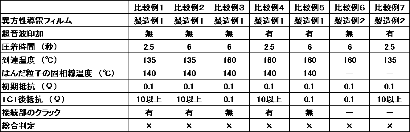
- the circuit members could be connected by crimping in a short time (5.0 seconds or less) by connection using ultrasonic waves.
- the crimping time is shorter (3.0 seconds or less), and the conduction resistance value after TCT is also very high. It was excellent.
- Comparative Example 1 the conduction resistance after TCT was insufficient and cracks were also observed. It did not change even when the crimping time was increased (Comparative Example 2).
- the crimping time should be at least 6 seconds.
- Comparative Example 3 Even when ultrasonic waves are used, if the ultimate temperature at the time of connection is higher than the solidus temperature of the solder particles, a short crimping time is insufficient in terms of the conduction resistance value after TCT and the occurrence of cracks. (Comparative Example 4).
- connection method of the circuit member of the present invention is excellent in connection reliability and can be connected in a short time when connecting the circuit member that has been rust-prevented by the rust inhibitor using the anisotropic conductive film, It can be suitably used for connecting circuit members.
Abstract
第1の回路部材の端子と第2の回路部材の端子とを接続させる回路部材の接続方法であって、前記第1の回路部材上に、ラジカル重合性物質と、有機過酸化物と、はんだ粒子とを含有する異方性導電フィルム、及び前記第2の回路部材を、この順で配置する配置工程と、前記第2の回路部材を押圧しつつ、前記異方性導電フィルムに超音波を印加して加熱する超音波印加工程とを含み、前記超音波印加工程における前記異方性導電フィルムの到達温度が、前記はんだ粒子の固相線温度以下であり、前記第1の回路部材の端子、及び前記第2の回路部材の端子の少なくともいずれかが、防錆剤による防錆処理がされている回路部材の接続方法である。
Description
本発明は、回路部材の接続方法、及び接合体に関する。
従来より、電子部品を基板と接続する手段として、導電性粒子が分散された熱硬化性樹脂を剥離フィルムに塗布したテープ状の接続材料(例えば、異方性導電フィルム(ACF;Anisotropic Conductive Film))が用いられている。
この異方性導電フィルムは、例えば、フレキシブルプリント基板(FPC)やIC(Integrated Circuit)チップの端子と、LCD(Liquid Crystal Display)パネルのガラス基板上に形成された電極とを接続する場合を始めとして、種々の端子同士を接着すると共に電気的に接続する場合に用いられている。
近年、回路部材の保護剤として、金属メッキに代わり、プリフラックス(OSP:Organic Solderability Preservative)と呼ばれる防錆剤が使用されている。前記プリフラックスとしては、例えば、イミダゾール系プリフラックスなどが知られている。
前記プリフラックスにより防錆処理がされた前記回路部材を、前記異方性導電フィルムを用いて接続すると、前記回路部材の端子上に存在するプリフラックス層が導通を阻害するという問題がある。そのため、この問題の解決が求められている。
前記プリフラックスにより防錆処理がされた前記回路部材を、前記異方性導電フィルムを用いて接続すると、前記回路部材の端子上に存在するプリフラックス層が導通を阻害するという問題がある。そのため、この問題の解決が求められている。
また、前記異方性導電フィルムを用いた接続においては、製造工程の短縮の点から、短時間で接続できることも求められている。
そこで、例えば、接続する電子部品の上接続部及び下接続部における電極を整列する段階と、前記上接続部の電極及び前記下接続部の電極の間に存在する接着剤に超音波エネルギーを印加し、前記接着剤自体からの発熱を利用して接着剤を硬化させる段階と、を包含する電子部品間の接続方法が提案されている(例えば、特許文献1参照)。
しかし、この提案の技術では、前述の前記プリフラックスにより防錆処理がされた前記回路部材を、前記異方性導電フィルムを用いて接続すると、前記回路部材の端子上に存在するプリフラックス層が導通を阻害するという問題は解消されない。
そこで、例えば、接続する電子部品の上接続部及び下接続部における電極を整列する段階と、前記上接続部の電極及び前記下接続部の電極の間に存在する接着剤に超音波エネルギーを印加し、前記接着剤自体からの発熱を利用して接着剤を硬化させる段階と、を包含する電子部品間の接続方法が提案されている(例えば、特許文献1参照)。
しかし、この提案の技術では、前述の前記プリフラックスにより防錆処理がされた前記回路部材を、前記異方性導電フィルムを用いて接続すると、前記回路部材の端子上に存在するプリフラックス層が導通を阻害するという問題は解消されない。
したがって、防錆剤により防錆処理がされた回路部材を異方性導電フィルムを用いて接続する際に、接続信頼性が優れ、かつ短時間で接続できる回路部材の接続方法、及び前記回路部材の接続方法により得られる接合体の提供が求められているのが現状である。
本発明は、従来における前記諸問題を解決し、以下の目的を達成することを課題とする。即ち、本発明は、防錆剤により防錆処理がされた回路部材を異方性導電フィルムを用いて接続する際に、接続信頼性が優れ、かつ短時間で接続できる回路部材の接続方法、及び前記回路部材の接続方法により得られる接合体を提供することを目的とする。
前記課題を解決するための手段としては、以下の通りである。即ち、
<1> 第1の回路部材の端子と第2の回路部材の端子とを接続させる回路部材の接続方法であって、
前記第1の回路部材上に、ラジカル重合性物質と、有機過酸化物と、はんだ粒子とを含有する異方性導電フィルム、及び前記第2の回路部材を、この順で配置する配置工程と、
前記第2の回路部材を押圧しつつ、前記異方性導電フィルムに超音波を印加して加熱する超音波印加工程とを含み、
前記超音波印加工程における前記異方性導電フィルムの到達温度が、前記はんだ粒子の固相線温度以下であり、
前記第1の回路部材の端子、及び前記第2の回路部材の端子の少なくともいずれかが、防錆剤による防錆処理がされていることを特徴とする回路部材の接続方法である。
<2> 有機過酸化物の1分間半減期温度が、110℃~135℃である前記<1>に記載の回路部材の接続方法である。
<3> 超音波印加工程における異方性導電フィルムの到達温度〔T(℃)〕が、下記式(1)を満たす前記<1>から<2>のいずれかに記載の回路部材の接続方法である。
〔式(1)〕
〔はんだ粒子の固相線温度(℃)-15(℃)〕≦T≦〔はんだ粒子の固相線温度(℃)〕
<4> はんだ粒子の固相線温度が、130℃~150℃である前記<1>から<3>のいずれかに記載の回路部材の接続方法である。
<5> 超音波が、第2の回路部材の平面に対して垂直に振動を有する前記<1>から<4>のいずれかに記載の回路部材の接続方法である。
<6> 前記<1>から<5>のいずれかに記載の回路部材の接続方法によって得られることを特徴とする接合体である。
本発明によれば、従来における前記諸問題を解決し、前記目的を達成することができ、防錆剤により防錆処理がされた回路部材を異方性導電フィルムを用いて接続する際に、接続信頼性が優れ、かつ短時間で接続できる回路部材の接続方法、及び前記回路部材の接続方法により得られる接合体を提供することができる。
(回路部材の接続方法、接合体)
本発明の回路部材の接続方法は、配置工程と、超音波印加工程とを少なくとも含み、更に必要に応じて、その他の工程を含む。
前記回路部材の接続方法は、第1の回路部材の端子と第2の回路部材の端子とを接続させる方法である。
前記接合体は、前記回路部材の接続方法によって得られる。
本発明の回路部材の接続方法は、配置工程と、超音波印加工程とを少なくとも含み、更に必要に応じて、その他の工程を含む。
前記回路部材の接続方法は、第1の回路部材の端子と第2の回路部材の端子とを接続させる方法である。
前記接合体は、前記回路部材の接続方法によって得られる。
<第1の回路部材、第2の回路部材>
前記第1の回路部材、及び前記第2の回路部材としては、端子を有し、前記異方性導電フィルムを用いた異方性導電接続の対象となる回路部材であれば、特に制限はなく、目的に応じて適宜選択することができ、例えば、端子を有するプラスチック基板、Flex-on-Board(フレックスオンボード、FOB)、Flex-on-Flex(フレックスオンフレックス、FOF)などが挙げられる。
前記第1の回路部材、及び前記第2の回路部材としては、端子を有し、前記異方性導電フィルムを用いた異方性導電接続の対象となる回路部材であれば、特に制限はなく、目的に応じて適宜選択することができ、例えば、端子を有するプラスチック基板、Flex-on-Board(フレックスオンボード、FOB)、Flex-on-Flex(フレックスオンフレックス、FOF)などが挙げられる。
前記端子の材質としては、特に制限はなく、目的に応じて適宜選択することができ、例えば、Cu、Auにてめっきを施したCu、Ni及びAuにてめっきを施したCu、Snにてめっきを施したCuなどが挙げられる。
前記端子を有するプラスチック基板の材質、構造としては、特に制限はなく、目的に応じて適宜選択することができ、例えば、端子を有するリジット基板、端子を有するフレキシブル基板などが挙げられる。前記端子を有するリジット基板としては、例えば、銅配線を有するガラスエポキシ基板などが挙げられる。前記端子を有するフレキシブル基板としては、例えば、銅配線を有するポリイミド基板などが挙げられる。
前記第1の回路部材、及び前記第2の回路部材の形状、大きさとしては、特に制限はなく、目的に応じて適宜選択することができる。
前記第1の回路部材、及び前記第2の回路部材は、同じ回路部材であってもよいし、異なる回路部材であってもよい。
前記第1の回路部材、及び前記第2の回路部材は、同じ回路部材であってもよいし、異なる回路部材であってもよい。
前記第1の回路部材の端子、及び前記第2の回路部材の端子の少なくともいずれかは、防錆剤による防錆処理がされている。
前記防錆剤としては、特に制限はなく、目的に応じて適宜選択することができる。前記防錆剤は、一般的に、プリフラックス又はOSP(Organic Solderability Preservative)と称されている。
前記防錆剤は、例えば、イミダゾール化合物と、銅イオンと、有機酸とを少なくとも含有する。前記イミダゾール化合物としては、例えば、ベンゾイミダゾールなどが挙げられる。前記ベンゾイミダゾールは置換基を有していてもよい。
前記防錆剤は、水溶性であることが好ましい。
前記防錆剤は、例えば、イミダゾール化合物と、銅イオンと、有機酸とを少なくとも含有する。前記イミダゾール化合物としては、例えば、ベンゾイミダゾールなどが挙げられる。前記ベンゾイミダゾールは置換基を有していてもよい。
前記防錆剤は、水溶性であることが好ましい。
前記防錆処理の方法としては、特に制限はなく、目的に応じて適宜選択することができ、例えば、処理される回路部材を、前記防錆剤、又は前記防錆剤を希釈して得られる水溶液に浸漬する方法などが挙げられる。
前記防錆処理を行うことで、回路部材上の端子、及び回路部分が保護される。
前記防錆処理を行うことで、回路部材上の端子、及び回路部分が保護される。
<配置工程>
前記配置工程としては、前記第1の回路部材上に、異方性導電フィルム、及び前記第2の回路部材を、この順で配置する工程であれば、特に制限はなく、目的に応じて適宜選択することができる。
前記配置工程としては、前記第1の回路部材上に、異方性導電フィルム、及び前記第2の回路部材を、この順で配置する工程であれば、特に制限はなく、目的に応じて適宜選択することができる。
前記配置工程は、前記第1の回路部材の端子上に、前記異方性導電フィルムを配置する第1の配置処理と、前記異方性導電フィルム上に、前記第2の回路部材を、前記第2の回路部材の端子が前記異方性導電フィルムと接するように配置する第2の配置処理とを含むことが好ましい。
-異方性導電フィルム-
前記異方性導電フィルムは、ラジカル重合性物質と、有機過酸化物と、はんだ粒子とを少なくとも含有し、更に必要に応じて、その他の成分を含有する。
前記異方性導電フィルムは、ラジカル重合性物質と、有機過酸化物と、はんだ粒子とを少なくとも含有し、更に必要に応じて、その他の成分を含有する。
--ラジカル重合性物質--
前記ラジカル重合性物質としては、特に制限はなく、目的に応じて適宜選択することができ、例えば、メチルアクリレート、エチルアクリレート、イソプロピルアクリレート、イソブチルアクリレート、エポキシアクリレート、エチレングリコールジアクリレート、ジエチレングリコールジアクリレート、トリメチロールプロパントリアクリレート、ジメチロールトリシクロデカンジアクリレート、テトラメチレングリコールテトラアクリレート、2-ヒドロキシ-1,3-ジアクリロキシプロパン、2,2-ビス[4-(アクリロキシメトキシ)フェニル]プロパン、2,2-ビス[4-(アクリロキシエトキシ)フェニル]プロパン、ジシクロペンテニルアクリレート、ジシクロペンタジエンジアクリレート、トリシクロデカニルアクリレート、イソシアヌル酸EO(エチレンオキサイド)変性ジアクリレート、イソシアヌル酸EO変性トリアクリレート、ウレタンアクリレートなどが挙げられる。これらは、1種単独で使用してもよいし、2種以上を併用してもよい。
また、前記アクリレートをメタクリレートにしたものが挙げられ、これらは、1種単独で使用してもよいし、2種以上を併用してもよい。
前記異方性導電フィルムにおける前記ラジカル重合性物質の含有量としては、特に制限はなく、目的に応じて適宜選択することができるが、10質量%~70質量%が好ましく、20質量%~60質量%がより好ましい。
--有機過酸化物--
前記有機過酸化物は、前記ラジカル重合性物質のラジカル重合開始剤である。
前記有機過酸化物としては、前記ラジカル重合性物質のラジカル重合を開始するものでれば、特に制限はなく、目的に応じて適宜選択することができ、例えば、ジラウロイルパーオキサイド、1,1,3,3-テトラメチルブチルパーオキシ-2-エチルヘキサノエート、ベンゾイルパーオキサイド、t-アミルパーオキシ-2-エチルヘキサノエート、t-ブチルパーオキシ-2-エチルヘキサノエート、t-ブチルパーオキシイソブチレート、t-ブチルパーオキシマレイン酸、1,1-ジ(t-アミルパーオキシ)-3,3,5-トリメチルシクロヘキサン、1,1-ジ(t-アミルパーオキシ)シクロヘキサン、t-アミルパーオキシイソノナノエート、t-アミルパーオキシノルマルオクトエート、1,1-ジ(t-ブチルパーオキシ)-3,3,5-トリメチルシクロヘキサン、1,1-ジ(t-ブチルパーオキシ)シクロヘキサン、t-ブチルパーオキシイソプロピルカーボネート、t-ブチルパーオキシ-2-エチルヘキシルカーボネート、2,5-ジメチル-2,5-ジ(ベンゾイルパーオキシ)ヘキサン、t-アミル-パーオキシベンゾエート、t-ブチルパーオキシアセテート、t-ブチルパーオキシイソノナノエート、2,2-ジ(t-ブチルパーオキシ)ブタン、t-ブチルパーオキシベンゾエート、ビス(4-t-ブチルシクロヘキシル)パーオキシジカーボネートなどが挙げられる。
これらは、1種単独で使用してもよいし、2種以上を併用してもよい。
前記有機過酸化物の1分間半減期温度としては、特に制限はなく、目的に応じて適宜選択することができるが、110℃~135℃であることが、得られる接合体の導通抵抗、及び耐クラック性に優れる点で、好ましい。
前記異方性導電フィルムにおける前記有機過酸化物の含有量としては、特に制限はなく、目的に応じて適宜選択することができるが、1質量%~10質量%が好ましく、2質量%~8質量%がより好ましい。
--はんだ粒子--
前記はんだ粒子としては、特に制限はなく、目的に応じて適宜選択することができる。
なお、はんだとは、錫、鉛などを主成分とする合金であって、一般的には、回路部材の導電金属と合金組織を形成可能、又はスルーホール内壁被膜と合金組織を形成可能な金属を含む合金である。
前記はんだ粒子としては、特に制限はなく、目的に応じて適宜選択することができる。
なお、はんだとは、錫、鉛などを主成分とする合金であって、一般的には、回路部材の導電金属と合金組織を形成可能、又はスルーホール内壁被膜と合金組織を形成可能な金属を含む合金である。
前記はんだ粒子としては、特に制限はなく、目的に応じて適宜選択することができ、例えば、Sn-Bi系はんだ、Sn-In系はんだなどが挙げられる。
前記はんだ粒子の固相線温度としては、特に制限はなく、目的に応じて適宜選択することができるが、110℃~170℃が好ましく、130℃~150℃がより好ましい。前記固相線温度が、前記より好ましい範囲内であると、低温接続の点で有利である。
なお、前記固相線温度とは、固相(固体)のはんだが溶け始める温度を意味する。
なお、前記固相線温度とは、固相(固体)のはんだが溶け始める温度を意味する。
前記はんだ粒子の平均粒径としては、特に制限はなく、目的に応じて適宜選択することができるが、1μm~50μmが好ましく、2μm~25μmがより好ましく、5μm~15μmが特に好ましい。
前記平均粒径は、任意に10個のはんだ粒子について測定した粒径の平均値である。
前記粒径は、例えば、走査型電子顕微鏡観察により測定できる。
前記平均粒径は、任意に10個のはんだ粒子について測定した粒径の平均値である。
前記粒径は、例えば、走査型電子顕微鏡観察により測定できる。
前記異方性導電フィルムにおける前記はんだ粒子の含有量としては、特に制限はなく、目的に応じて適宜選択することができるが、1質量%~20質量%が好ましく、4質量%~16質量%がより好ましい。
--その他の成分--
前記その他の成分としては、特に制限はなく、目的に応じて適宜選択することができ、例えば、膜形成樹脂、シランカップリング剤などが挙げられる。
前記その他の成分としては、特に制限はなく、目的に応じて適宜選択することができ、例えば、膜形成樹脂、シランカップリング剤などが挙げられる。
---膜形成樹脂---
前記膜形成樹脂としては、特に制限はなく、目的に応じて適宜選択することができ、例えば、フェノキシ樹脂、不飽和ポリエステル樹脂、飽和ポリエステル樹脂、ウレタン樹脂、ブタジエン樹脂、ポリイミド樹脂、ポリアミド樹脂、ポリオレフィン樹脂などが挙げられる。前記膜形成樹脂は、1種単独で使用してもよいし、2種以上を併用してもよい。これらの中でも、製膜性、加工性、接続信頼性の点からフェノキシ樹脂が好ましい。
前記フェノキシ樹脂としては、例えば、ビスフェノールAとエピクロルヒドリンより合成される樹脂などが挙げられる。
前記フェノキシ樹脂は、適宜合成したものを使用してもよいし、市販品を使用してもよい。
前記膜形成樹脂としては、特に制限はなく、目的に応じて適宜選択することができ、例えば、フェノキシ樹脂、不飽和ポリエステル樹脂、飽和ポリエステル樹脂、ウレタン樹脂、ブタジエン樹脂、ポリイミド樹脂、ポリアミド樹脂、ポリオレフィン樹脂などが挙げられる。前記膜形成樹脂は、1種単独で使用してもよいし、2種以上を併用してもよい。これらの中でも、製膜性、加工性、接続信頼性の点からフェノキシ樹脂が好ましい。
前記フェノキシ樹脂としては、例えば、ビスフェノールAとエピクロルヒドリンより合成される樹脂などが挙げられる。
前記フェノキシ樹脂は、適宜合成したものを使用してもよいし、市販品を使用してもよい。
前記異方性導電フィルムにおける前記膜形成樹脂の含有量としては、特に制限はなく、目的に応じて適宜選択することができるが、20質量%~70質量%が好ましく、30質量%~60質量%がより好ましい。
---シランカップリング剤---
前記シランカップリング剤としては、特に制限はなく、目的に応じて適宜選択することができ、例えば、ビニルトリス(2-メトキシエトキシ)シラン、ビニルトリエトキシシラン、ビニルトリメトキシシラン、3-スチリルトリメトキシシラン、3-メタクリロキシプロピルトリメトキシシラン、3-メタクリロキシプロピルトリエトキシシラン、3-アクリロキシプロピルトリメトキシシラン、3-グリシドキシプロピルトリメトキシシラン、3-グリシドキシプロピルメチルジエトキシシラン、N-2-(アミノエチル)-3-アミノプロピルトリメトキシシラン、N-2-(アミノエチル)-3-アミノプロピルメチルジメトキシシラン、3-アミノプロピルトリエトキシシラン、N-フェニル-3-アミノプロピルトリメトキシシラン、3-メルカプトプロピルトリメトキシシラン、3-クロロプロピルトリメトキシシランなどが挙げられる。
前記シランカップリング剤としては、特に制限はなく、目的に応じて適宜選択することができ、例えば、ビニルトリス(2-メトキシエトキシ)シラン、ビニルトリエトキシシラン、ビニルトリメトキシシラン、3-スチリルトリメトキシシラン、3-メタクリロキシプロピルトリメトキシシラン、3-メタクリロキシプロピルトリエトキシシラン、3-アクリロキシプロピルトリメトキシシラン、3-グリシドキシプロピルトリメトキシシラン、3-グリシドキシプロピルメチルジエトキシシラン、N-2-(アミノエチル)-3-アミノプロピルトリメトキシシラン、N-2-(アミノエチル)-3-アミノプロピルメチルジメトキシシラン、3-アミノプロピルトリエトキシシラン、N-フェニル-3-アミノプロピルトリメトキシシラン、3-メルカプトプロピルトリメトキシシラン、3-クロロプロピルトリメトキシシランなどが挙げられる。
前記異方性導電フィルムにおける前記シランカップリング剤の含有量としては、特に制限はなく、目的に応じて適宜選択することができる。
前記異方性導電フィルムの平均厚みとしては、特に制限はなく、目的に応じて適宜選択することができるが、5μm~50μmが好ましく、15μm~45μmがより好ましい。
<超音波印加工程>
前記超音波印加工程としては、前記第2の回路部材を押圧しつつ、前記異方性導電フィルムに超音波を印加して加熱する工程であれば、特に制限はなく、目的に応じて適宜選択することができる。
前記超音波印加工程における前記異方性導電フィルムの到達温度は、前記はんだ粒子の固相線温度以下である。
前記超音波印加工程としては、前記第2の回路部材を押圧しつつ、前記異方性導電フィルムに超音波を印加して加熱する工程であれば、特に制限はなく、目的に応じて適宜選択することができる。
前記超音波印加工程における前記異方性導電フィルムの到達温度は、前記はんだ粒子の固相線温度以下である。
前記第2の回路部材を押圧する方法としては、特に制限はなく、目的に応じて適宜選択することができ、例えば、超音波振動子が内蔵された超音波印加可能な押圧部材などが挙げられる。
前記押圧部材の先端形状としては、特に制限はなく、目的に応じて適宜選択することができ、例えば、平面状、曲面状などが挙げられる。なお、前記先端形状が曲面状である場合、前記曲面状に沿って押圧してもよい。
前記押圧の押圧力としては、特に制限はなく、目的に応じて適宜選択することができるが、0.5MPa~100MPaが好ましい。
前記押圧の時間(圧着時間)としては、特に制限はなく、目的に応じて適宜選択することができるが、5.0秒間以下が好ましく、3.0秒間以下がより好ましい。前記押圧の時間(圧着時間)が、5.0秒間を超えると、短時間での圧着とはいえない。
前記異方性導電フィルムへの超音波の印加の方法としては、特に制限はなく、目的に応じて適宜選択することができ、例えば、前記第2の回路部材に超音波振動子が内蔵された超音波印加可能な押圧部材を押し当てる方法などが挙げられる。
前記超音波の周波数としては、特に制限はなく、目的に応じて適宜選択することができるが、10kHz~100kHzが好ましく、20kHz~60kHzがより好ましい。前記周波数が、10kHz未満であると、回路部材を押し込む力が足りず、接続不良を生じることがあり、100kHzを超えると、回路部材の接合端子が変形してショートや接続不良を引き起こすことがある。
前記超音波の振動方向としては、特に制限はなく、目的に応じて適宜選択することができ、前記第2の回路部材の平面に対して、水平振動であってもよいし、垂直振動であってもよいが、垂直振動であることが好ましい。即ち、前記超音波は、前記第2の回路部材の平面に対して垂直に振動を有することが好ましい。そうすることにより、アライメントずれを防止できる。
前記超音波の印加時間としては、特に制限はなく、目的に応じて適宜選択することができるが、0.1秒間~5.0秒間が好ましく、0.5秒間~3.0秒間がより好ましい。前記超音波の印加時間が、0.1秒間未満であると、回路部材の押し込み不足が発生することがあり、5.0秒間を超えると、短時間接続とは言えない。
前記超音波印加工程における前記異方性導電フィルムの到達温度〔T(℃)〕は、前記はんだ粒子の固相線温度以下であり、下記式(1)を満たすことが好ましい。
〔式(1)〕
〔はんだ粒子の固相線温度(℃)-15(℃)〕≦T≦〔はんだ粒子の固相線温度(℃)〕
前記到達温度が、上記式(1)を満たすことにより、より短い圧着時間で接続ができ、かつ接続信頼性(例えば、TCT後の導通抵抗値)も非常に優れる。
〔式(1)〕
〔はんだ粒子の固相線温度(℃)-15(℃)〕≦T≦〔はんだ粒子の固相線温度(℃)〕
前記到達温度が、上記式(1)を満たすことにより、より短い圧着時間で接続ができ、かつ接続信頼性(例えば、TCT後の導通抵抗値)も非常に優れる。
以下、本発明の実施例を説明するが、本発明は、これらの実施例に何ら限定されるものではない。
(製造例1~6)
<異方性導電フィルムの作製>
下記表1に示す原材料を、下記表1に示す配合量で混合した後、導電性粒子を均一に分散して異方性導電組成物を得た。
得られた異方性導電組成物を、ポリエチレンテレフタレートフィルム上に平均厚みが30μmになるように塗布して、異方性導電フィルムを得た。
<異方性導電フィルムの作製>
下記表1に示す原材料を、下記表1に示す配合量で混合した後、導電性粒子を均一に分散して異方性導電組成物を得た。
得られた異方性導電組成物を、ポリエチレンテレフタレートフィルム上に平均厚みが30μmになるように塗布して、異方性導電フィルムを得た。

表1中の各物質は、以下の通りである。
DCP:ジシクロペンタジエンジメタクリレート(新中村化学工業株式会社製)
M315:イソシアヌル酸EO変性ジ及びトリアクリレート(アロニックスM315、東亞合成工業株式会社製)
M1600:ウレタンアクリレート(アロニックスM1600、東亞合成工業株式会社製)
YP50:フェノキシ樹脂(新日鐵化学株式会社製)
SG80H:グリシジル基含有アクリルゴム(ナガセケムテックス株式会社製)
KBE-503:3-メタクリロキシプロピルトリエトキシシラン(信越化学工業株式会社製)
ナイパーBW:有機過酸化物〔日油株式会社製、ベンゾイルパーオキサイド、1分間半減期温度(130.0℃)〕
パーロイルL:有機過酸化物〔日油株式会社製、ジラウロイルパーオキサイド、1分間半減期温度(116.4℃)〕
はんだ粒子1:Sn(47)-Bi(53)系ハンダ粒子。水アトマイズ法により、溶融した合金をノズルから水中に噴霧し、急冷して凝固させて得た。平均粒径は10μm。固相線温度は140℃。
はんだ粒子2:Cd18-Pb32-Sn50。平均粒径は10μm。固相線温度は145℃。
Ni/Au:Ni/Auメッキ金属粒子(日本化学工業株式会社製、平均粒径6μm)
(実施例1~7、比較例1~7)
<接合体の製造>
以下の方法により接合体を製造した。
第1の回路部材として、評価用PWB(デクセリアルズ株式会社評価用基材、200μmピッチ、Cu35μm厚み、FR-4基材)を用いた。前記評価用PWBは、水溶性プリフラックス(F2LX、四国化成工業株式会社製)でプリフラックス処理をした。
第2の回路部材として、評価用FPC(デクセリアルズ株式会社評価用基材、200μmピッチ、Cu12μm厚み-Ni/Auめっき、PI25μm厚み-エスパネックス基材)を用いた。
前記第1の回路部材上に、幅1.5mmにスリットした前記異方性導電フィルムを配置した。配置する際、80℃、1MPa、1秒間で貼り付けた。続いて、その異方性導電フィルム上に、前記第2の回路部材を前記異方性導電フィルムからはみ出さないように配置した。続いて、緩衝材(シリコーンゴム、厚み0.2mm)を介して、超音波印加ボンダー(振動50kHz、振幅(縦振動15μm))を用いて、表2及び表3に示す接続条件で、前記第2の回路部材を2MPaの押圧力で押圧し、接合体を得た。また、超音波の印加時間は、圧着時間と同一とした。なお、超音波印加ボンダーを用いた場合には、超音波の印加により異方性導電フィルムが加熱されるため、加熱ツールは用いなかった。一方、超音波を印加しない場合には、超音波印加ボンダーに代えて、加熱ツールを用いた。
<評価>
作製した接合体について、以下の評価を行った。結果を表2及び表3に示す。
作製した接合体について、以下の評価を行った。結果を表2及び表3に示す。
<<導通抵抗>>
接合体の初期の導通抵抗値(Ω)、及び温度サイクル試験(TCT)後の導通抵抗値(Ω)を以下の方法で測定した。
具体的には、上記接合体の製造と同様の方法で、図1に示すような試験体を作製にして、デジタルマルチメーター(品番:デジタルマルチメータ43301A、アジレント・テクノロジー株式会社製)を用いて4端子法にて電流1mAを流したときの抵抗値を測定した。30チャンネルについて抵抗値を測定し、最大の抵抗値を測定値とした。図1において、符号1は、FR-4基材を示し、符号2は、ACFを示し、符号3は、FPCのパターンを示し、符号4は、Cu配線を示し、符号Aは、測定箇所を示す。
なお、TCTは、-55℃の低温条件と、125℃の高温条件とを15分間隔で繰り返し実施した。TCTは300サイクルまで実施した。
<<クラックの発生>>
TCT後、はんだ粒子を用いた接合体について、端子が接続されている箇所にクラックが発生しているかどうかを、電子顕微鏡により確認し、以下の評価基準で評価した。
〔評価基準〕
無:クラックの発生が見られない。
有:1箇所以上でクラックの発生が見られる。
TCT後、はんだ粒子を用いた接合体について、端子が接続されている箇所にクラックが発生しているかどうかを、電子顕微鏡により確認し、以下の評価基準で評価した。
〔評価基準〕
無:クラックの発生が見られない。
有:1箇所以上でクラックの発生が見られる。
<<総合判定>>
上記評価の結果、及び圧着時間から、下記評価基準で総合判定を行った。
〔評価基準〕
○:下記条件1~5を全て満たす。
△:下記条件1~3を満たすが、下記条件4及び5の少なくともいずれかを満たさない。
×:下記条件1~3のいずれかを満たさない。
条件1:圧着時間が5.0秒間以下
条件2:初期抵抗、及びTCT後抵抗が2.0Ω以下
条件3:クラックの発生がない
条件4:圧着時間が3.0秒間以下
条件5:初期抵抗、及びTCT後抵抗が0.5Ω以下
上記評価の結果、及び圧着時間から、下記評価基準で総合判定を行った。
〔評価基準〕
○:下記条件1~5を全て満たす。
△:下記条件1~3を満たすが、下記条件4及び5の少なくともいずれかを満たさない。
×:下記条件1~3のいずれかを満たさない。
条件1:圧着時間が5.0秒間以下
条件2:初期抵抗、及びTCT後抵抗が2.0Ω以下
条件3:クラックの発生がない
条件4:圧着時間が3.0秒間以下
条件5:初期抵抗、及びTCT後抵抗が0.5Ω以下

実施例1~7では、超音波を用いた接続により、短時間(5.0秒間以下)の圧着で回路部材の接続を行うことができた。特に、接続時の到達温度が、前記式(1)を満たす条件(例えば、実施例1~5)では、圧着時間がより短く(3.0秒間以下)かつTCT後の導通抵抗値も非常に優れていた。
比較例1では、TCT後の導通抵抗が不十分であり、かつクラックも見られた。それは、圧着時間を長くしても変わらなかった(比較例2)。
超音波を用いず、かつ接続時の到達温度をはんだ粒子の固相線温度より高くした場合、導通抵抗値、及びクラックが良好なものが得られるには、圧着時間を少なくても6秒間にする必要があった(比較例3)。
超音波を用いても、接続時の到達温度がはんだ粒子の固相線温度より高いと、短時間の圧着時間では、TCT後の導通抵抗値、及びクラックの発生の点で、不十分であった(比較例4)。
また、超音波を用いても、接続時の到達温度がはんだ粒子の固相線温度より高いと、導通抵抗値、及びクラックが良好なものが得られるには、圧着時間を少なくても6秒間にする必要があった(比較例5)。
通常の異方性導電フィルム(はんだ粒子を含有していない異方性導電フィルム)を用いた、超音波を用いない通常の接続の場合には、導通抵抗値が良好なものが得られるには、圧着時間を少なくても6秒間にする必要があった(比較例6)。
通常の異方性導電フィルム(はんだ粒子を含有していない異方性導電フィルム)を用いた、超音波を用いた接続の場合には、TCT後の抵抗値(10Ω以上)が不十分であった(比較例7)。
本発明の回路部材の接続方法は、防錆剤により防錆処理がされた回路部材を異方性導電フィルムを用いて接続する際に、接続信頼性が優れ、かつ短時間で接続できるため、回路部材の接続に好適に用いることができる。
1 FR-4基材
2 ACF
3 FPCのパターン
4 Cu配線
A 測定箇所
2 ACF
3 FPCのパターン
4 Cu配線
A 測定箇所
Claims (6)
- 第1の回路部材の端子と第2の回路部材の端子とを接続させる回路部材の接続方法であって、
前記第1の回路部材上に、ラジカル重合性物質と、有機過酸化物と、はんだ粒子とを含有する異方性導電フィルム、及び前記第2の回路部材を、この順で配置する配置工程と、
前記第2の回路部材を押圧しつつ、前記異方性導電フィルムに超音波を印加して加熱する超音波印加工程とを含み、
前記超音波印加工程における前記異方性導電フィルムの到達温度が、前記はんだ粒子の固相線温度以下であり、
前記第1の回路部材の端子、及び前記第2の回路部材の端子の少なくともいずれかが、防錆剤による防錆処理がされていることを特徴とする回路部材の接続方法。 - 有機過酸化物の1分間半減期温度が、110℃~135℃である請求項1に記載の回路部材の接続方法。
- 超音波印加工程における異方性導電フィルムの到達温度〔T(℃)〕が、下記式(1)を満たす請求項1から2のいずれかに記載の回路部材の接続方法。
〔式(1)〕
〔はんだ粒子の固相線温度(℃)-15(℃)〕≦T≦〔はんだ粒子の固相線温度(℃)〕 - はんだ粒子の固相線温度が、130℃~150℃である請求項1から3のいずれかに記載の回路部材の接続方法。
- 超音波が、第2の回路部材の平面に対して垂直に振動を有する請求項1から4のいずれかに記載の回路部材の接続方法。
- 請求項1から5のいずれかに記載の回路部材の接続方法によって得られることを特徴とする接合体。
Applications Claiming Priority (2)
| Application Number | Priority Date | Filing Date | Title |
|---|---|---|---|
| JP2013069141A JP2014192486A (ja) | 2013-03-28 | 2013-03-28 | 回路部材の接続方法、及び接合体 |
| JP2013-069141 | 2013-03-28 |
Publications (1)
| Publication Number | Publication Date |
|---|---|
| WO2014156930A1 true WO2014156930A1 (ja) | 2014-10-02 |
Family
ID=51623909
Family Applications (1)
| Application Number | Title | Priority Date | Filing Date |
|---|---|---|---|
| PCT/JP2014/057696 WO2014156930A1 (ja) | 2013-03-28 | 2014-03-20 | 回路部材の接続方法、及び接合体 |
Country Status (3)
| Country | Link |
|---|---|
| JP (1) | JP2014192486A (ja) |
| TW (1) | TW201442584A (ja) |
| WO (1) | WO2014156930A1 (ja) |
Cited By (2)
| Publication number | Priority date | Publication date | Assignee | Title |
|---|---|---|---|---|
| JP2016134366A (ja) * | 2015-01-22 | 2016-07-25 | デクセリアルズ株式会社 | 異方性導電フィルム、及び接続方法 |
| JP2016148012A (ja) * | 2015-02-05 | 2016-08-18 | 太陽インキ製造株式会社 | 硬化性組成物および電子部品 |
Citations (5)
| Publication number | Priority date | Publication date | Assignee | Title |
|---|---|---|---|---|
| JPH04292803A (ja) * | 1991-03-20 | 1992-10-16 | Hitachi Ltd | 異方導電性フィルム |
| JPH05290946A (ja) * | 1992-04-03 | 1993-11-05 | Hitachi Ltd | 電子部品実装方法 |
| JP2003100367A (ja) * | 2001-09-20 | 2003-04-04 | Denso Corp | 導電性接着剤、この接着剤を用いた回路基板間の接続方法および回路基板間の接続構造 |
| WO2011059084A1 (ja) * | 2009-11-16 | 2011-05-19 | 日立化成工業株式会社 | 回路接続材料及びそれを用いた回路部材の接続構造 |
| JP2012126915A (ja) * | 2012-03-16 | 2012-07-05 | Hitachi Chemical Co Ltd | 異方導電フィルム、接続体及び半導体装置 |
-
2013
- 2013-03-28 JP JP2013069141A patent/JP2014192486A/ja active Pending
-
2014
- 2014-03-20 WO PCT/JP2014/057696 patent/WO2014156930A1/ja active Application Filing
- 2014-03-25 TW TW103111095A patent/TW201442584A/zh unknown
Patent Citations (5)
| Publication number | Priority date | Publication date | Assignee | Title |
|---|---|---|---|---|
| JPH04292803A (ja) * | 1991-03-20 | 1992-10-16 | Hitachi Ltd | 異方導電性フィルム |
| JPH05290946A (ja) * | 1992-04-03 | 1993-11-05 | Hitachi Ltd | 電子部品実装方法 |
| JP2003100367A (ja) * | 2001-09-20 | 2003-04-04 | Denso Corp | 導電性接着剤、この接着剤を用いた回路基板間の接続方法および回路基板間の接続構造 |
| WO2011059084A1 (ja) * | 2009-11-16 | 2011-05-19 | 日立化成工業株式会社 | 回路接続材料及びそれを用いた回路部材の接続構造 |
| JP2012126915A (ja) * | 2012-03-16 | 2012-07-05 | Hitachi Chemical Co Ltd | 異方導電フィルム、接続体及び半導体装置 |
Cited By (5)
| Publication number | Priority date | Publication date | Assignee | Title |
|---|---|---|---|---|
| JP2016134366A (ja) * | 2015-01-22 | 2016-07-25 | デクセリアルズ株式会社 | 異方性導電フィルム、及び接続方法 |
| WO2016117350A1 (ja) * | 2015-01-22 | 2016-07-28 | デクセリアルズ株式会社 | 異方性導電フィルム、及び接続方法 |
| CN107112658A (zh) * | 2015-01-22 | 2017-08-29 | 迪睿合株式会社 | 各向异性导电膜和连接方法 |
| CN107112658B (zh) * | 2015-01-22 | 2019-07-12 | 迪睿合株式会社 | 各向异性导电膜和连接方法 |
| JP2016148012A (ja) * | 2015-02-05 | 2016-08-18 | 太陽インキ製造株式会社 | 硬化性組成物および電子部品 |
Also Published As
| Publication number | Publication date |
|---|---|
| JP2014192486A (ja) | 2014-10-06 |
| TW201442584A (zh) | 2014-11-01 |
Similar Documents
| Publication | Publication Date | Title |
|---|---|---|
| JP5833809B2 (ja) | 異方性導電フィルム、接合体及び接続方法 | |
| JP4897778B2 (ja) | 接続フィルム、並びに、接合体及びその製造方法 | |
| JP5690648B2 (ja) | 異方性導電フィルム、接続方法及び接続構造体 | |
| KR101814235B1 (ko) | 이방성 도전 필름, 접속 방법 및 접속 구조체 | |
| JP5140816B2 (ja) | 接合体及びその製造方法 | |
| TWI655267B (zh) | Conductive adhesive and connection method of electronic parts | |
| JP2009170898A (ja) | 回路接続材料及び回路部材の接続構造 | |
| KR101886909B1 (ko) | 이방성 도전 접속 재료, 접속 구조체, 접속 구조체의 제조 방법 및 접속 방법 | |
| TWI681694B (zh) | 各向異性導電薄膜、及其連接方法 | |
| JPWO2020004510A1 (ja) | 異方性導電フィルム及びその製造方法並びに接続構造体の製造方法 | |
| JP5972564B2 (ja) | 接続方法、接続構造体、異方性導電フィルム及びその製造方法 | |
| WO2014156930A1 (ja) | 回路部材の接続方法、及び接合体 | |
| JP7006029B2 (ja) | 回路接続用接着剤組成物及び構造体 | |
| JP6425382B2 (ja) | 接続方法、及び接合体 | |
| JP4513147B2 (ja) | 回路接続方法 | |
| JP2010135255A (ja) | 異方性導電フィルム、並びに、接合体及びその製造方法 | |
| KR20110131018A (ko) | 이방성 도전 필름용 도전 입자 및 이를 포함하는 이방성 도전 필름 | |
| WO2023234056A1 (ja) | 回路接続構造体の製造方法及び回路接続装置 | |
| JP2013051352A (ja) | 配線基板の接続方法 | |
| JP5966069B2 (ja) | 異方性導電フィルム、接合体及び接続方法 | |
| JP2002226807A (ja) | 回路接続用接着剤及びそれを用いた回路接続方法、接続構造体 | |
| JP6286473B2 (ja) | 接合体 | |
| TW201635312A (zh) | 各向異性導電薄膜、連接方法、及其接合體 | |
| JP2011018945A (ja) | 接合体及びその製造方法 | |
| JP5924896B2 (ja) | 接合体の製造方法 |
Legal Events
| Date | Code | Title | Description |
|---|---|---|---|
| 121 | Ep: the epo has been informed by wipo that ep was designated in this application |
Ref document number: 14773854 Country of ref document: EP Kind code of ref document: A1 |
|
| DPE1 | Request for preliminary examination filed after expiration of 19th month from priority date (pct application filed from 20040101) | ||
| NENP | Non-entry into the national phase |
Ref country code: DE |
|
| 122 | Ep: pct application non-entry in european phase |
Ref document number: 14773854 Country of ref document: EP Kind code of ref document: A1 |